4S Low Pass Filter - Four State QRP Group
12
4S‐Low Pass Filter Designed by David Cripe, NMØS Copyright 2015 David Cripe NMØS Four State QRP Group
Transcript of 4S Low Pass Filter - Four State QRP Group

4S‐Low Pass FilterDesigned by David Cripe, NMØS
Copyright 2015 David Cripe NMØS Four State QRP Group

Introduction• Thank you for purchasing the 4SLPF kit.• These instructions are for both the 80M and 40Mkits.
• The FCC requires all spurious emissions below 30Mcto be attenuated by 43 dB or more below the carrier,this includes QRP transmitters.
• A Pittsburg style PC Board, spiral PCB inductors, anda PCB case have been provided an easy buildingexperience.
• Note that the kit doesn't include a balun for balanced lineantennas. They are very easy to construct and your favoritesearch engine will find many examples.

Specifications
Harmonic Attenuation dBc2nd 3rd
80M Midpoint ‐57 ‐5940M Midpoint ‐56 ‐59
• Maximum Power Capability: Designed and tested for 100 watts.
• Impedance: 50 ohms in 50 ohms out. • Extremely low insertion loss, nearly zero.

AssemblyStep 1.Inventory the parts.
Step 2.Break the 2 PC boards into 8 pieces. Sand any rough edges lightly.
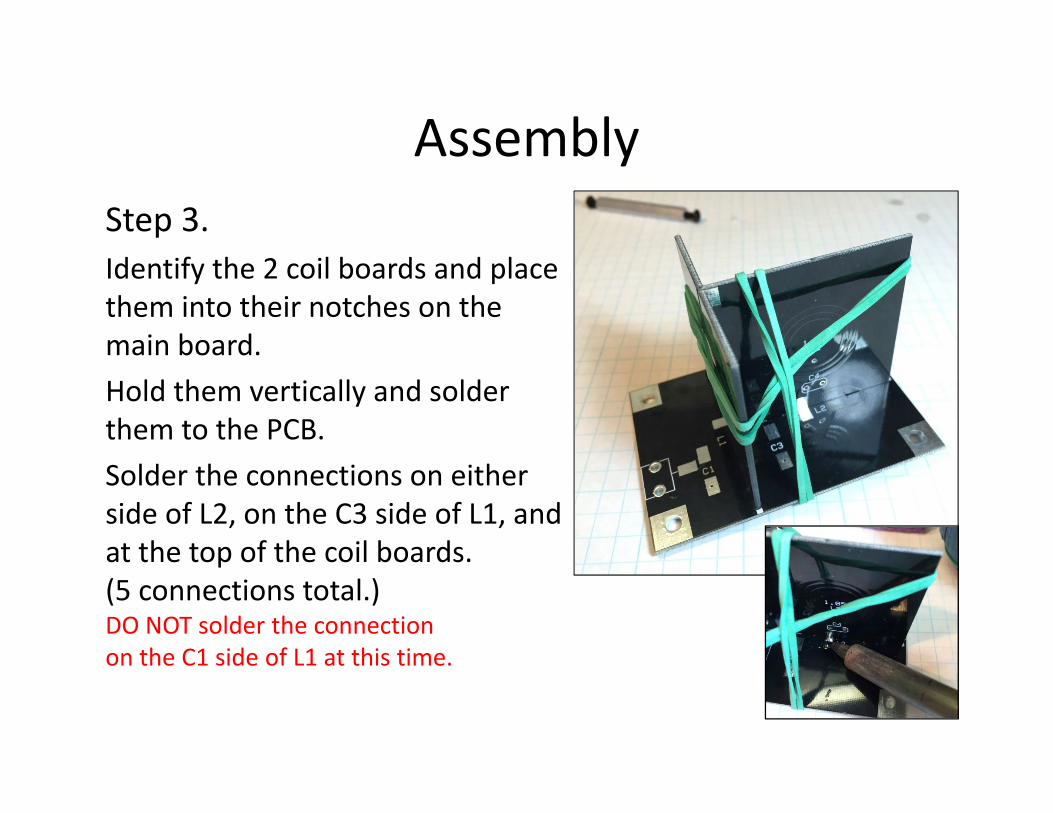
AssemblyStep 3.Identify the 2 coil boards and place them into their notches on the main board. Hold them vertically and solder them to the PCB. Solder the connections on either side of L2, on the C3 side of L1, and at the top of the coil boards. (5 connections total.) DO NOT solder the connection on the C1 side of L1 at this time.

AssemblyStep 4.Assemble the cover base and the board with the 4SQRP Label. Use the L1/C1 side of the board assembled in Step 3, to make sure you solder these 2 boards at a 90 degree right angle.
Note: Snip the corner of the L1/C1 board so it won’t interfere with the enclosure.

AssemblyStep 5.Now dry fit the remaining 3 boards to the cover base assembly. Make sure the notches are pointing away from the cover board. Place a couple of rubber bands around the loose assembly and make sure everything is square before soldering.
(Re‐flow the joint created in step 4 if needed.)

AssemblyStep 6.Now solder all connections on the cover assemblyStep 7. Solder the remaining connection near L1/C1 at this time.

AssemblyStep 8 aSolder in the capacitors, checking their values against the parts list, and matching them to the correct position on the pc board.C4 and C2 are standard thru‐hole parts mounted on the vertical coil boardsNOTE: C1 on the L1 board should have been marked C2.

AssemblyStep 8 bC1, C3, and C5 are mounted Pittsburg style on the main board. You will need to bend the leads before soldering these capacitors. Bend them in a “W” shape for easier installation.
Step 8 cThe center lead on J1 & J2 will also need to be formed before mounting.

AssemblyStep 9.Screw the stand‐offs to the main PCB using 4 of the screws.
Screw the cover to the main PCB using the remaining 4 screws.

That’s it! Check off each part as it’s installed, and refer to the pictures for more detail.