4181 Voltex CIP nl.qxp 1/10/2005 2:26 PM Page 1 VOLTEX Voltex Product... · TERMINATION BAR:Min. 1"...
24
VOLTEX ® V OLCLAY WATERPROOFING VOLCLAY BENTONITE GEOTEXTILE WATERPROOFING PRODUCT MANUAL FOR CAST - IN - PLACE CONCRETE APPLICATIONS Certified to ANSI/NSF 61
Transcript of 4181 Voltex CIP nl.qxp 1/10/2005 2:26 PM Page 1 VOLTEX Voltex Product... · TERMINATION BAR:Min. 1"...

VOLTEX ®
VOLCLAY WATERPROOFING
VOLCLAY BENTONITE GEOTEXTILEWATERPROOFING
PRODUCT MMANUALFOR
CAST-IIN-PPLACE CONCRETE AAPPLICATIONS
Certified toANSI/NSF 61
4181 Voltex CIP_nl.qxp 1/10/2005 2:26 PM Page 1

THIS MANUAL CONTAINS THE INSTALLATIONGUIDELINES FOR THE VOLTEX AND VOLTEX DSWATERPROOFING SYSTEM FOR CAST-IN-PLACECONCRETE APPLICATIONS, INCLUDING UNDERSLAB,PROPERTY LINE WALLS, AND BACKFILLED WALLS.THIS MANUAL DOES NOT COVER SHOTCRETE,MASONRY BLOCK, OR PRECAST CONCRETEAPPLICATIONS. FOR APPLICATIONS NOT COVERED INTHIS MANUAL, CONTACT CETCO FOR SPECIFICINSTALLATION GUIDELINES. BEFORE INSTALLATION,READ THIS MANUAL TO GAIN FAMILIARITY WITHSPECIFIC PROCEDURES AND APPLICATIONS. IN THISMANUAL THE PRODUCT NAME “VOLTEX” IS USEDGENERICALLY FOR ALL VOLTEX PRODUCT TYPES.
C O N T E N T SWHAT IS VOLCLAY?PRODUCT DESCRIPTIONASSOCIATED SYSTEM PRODUCTSACCESSORIESLIMITATIONS
INSTALLATION GUIDELINESSECTION 1: UNDERSLAB INSTALLATION
1.1 Substrate Preparation1.2 Installation1.3 Pile Caps & Grade Beams1.4 Slab Penetrations1.5 Elevator Pits1.6 Edge of Slab, Backfilled Walls1.7 Edge of Slab, Property Line Walls
SECTION 2: PROPERTY LINE CONSTRUCTION2.1 Property Line Installation Guidelines2.2 Soldier Pile & Lagging2.3 Metal Sheet Piling Retaining Wall2.4 Earth Formed Shotcrete Retention2.5 Auger Cast Caisson Retention Wall
SECTION 3: BACKFILLED WALLS3.1 Surface Preparation3.2 Installation3.3 Backfilled Wall Penetrations3.4 Terminations3.5 Masonry Block Walls
SECTION 4: TUNNELS/EARTH COVERED ROOFS4.1 Installation
SECTION 5: SPECIAL CONDITIONS5.1 Precast Concrete Construction5.2 Contaminated Conditions5.3 High Hydrostatic Pressure Conditions
-2 -
V O L C L AY V O LT E X / V O LT E X D S ®
B E N T O N I T E G E O T E X T I L E W AT E R P R O O F I N G
WHAT IS VOLCLAY® ?Volclay sodium bentonite is a non-toxic mineral ofvolcanic origin found exclusively in the Black Hills regionof the United States. Volclay is specially processed byCETCO to achieve the highest possible performance forall of our waterproofing products. CETCO also manufac-turers Volclay CR, a contaminant resistant bentonite toassure optimum performance in saline or contaminatedwater.
Volclay prevents water intrusion by forming a densemonolithic membrane upon contact with water. The spe-cially processed Volclay expands under confinement,forming an impervious membrane that will be maintainedfor the life of the structure.
PRODUCT DESCRIPTIONVoltex® is a highly effective waterproofing composite com-prised of two polypropylene geotextiles and a minimum1.10 pound of Volclay sodium bentonite per square foot.The two geotextiles are interlocked by a patentedneedlepunching process which encapsulates and con-fines the bentonite. Voltex DS® integrates a polyethylene(PE) liner bonded to the outside surface of the non-woven geotextile. The PE liner provides extremely lowpermeabilities for water vapor and gas transmission.
Figure 1 - Cross Section illustration of Voltex waterproofing membrane mechanically bonded to concrete.
Concrete
Needlepunched Geotextile Fibers
1.10 lbs. of Granular Volclay®
Sodium Bentonite per square foot
Nonwoven Geotextile
Woven Geotextile
Voltex® forms acontinuousmechanical bondto concrete. Thisbond is createdwhen Voltex’sstrong geotextilefibers areencapsulated bypoured concreteas shown in theillustration.
4181 Voltex CIP_nl.qxp 1/10/2005 2:26 PM Page 2

V O L C L AY V O LT E X / V O LT E X D S ®
B E N T O N I T E G E O T E X T I L E W AT E R P R O O F I N G
- 3 -
Installation of Voltex is fast and easy. Simply position theproduct into place and fasten. Voltex can be installed ongreen concrete, in virtually any weather, without the needfor primers or adhesives. Voltex can be easily cut on siteto form around corners and penetrations. The result isalways a consistent self-healing membrane.
DURABILITYThe Volclay® sodium bentonite in Voltex is uniformlyencapsulated between two high-strength woven andnon-woven geotextiles. CETCO’s state-of-the-artneedlepunching process interlocks the geotextiles, pre-venting the displacement of bentonite prior to, during, andafter installation. The geotextiles provide superior protec-tion from inclement weather and construction-relateddamage, without requiring to use a protection course.
SUPERIOR ADHESIONWhen concrete is poured against Voltex, a tenaciousmechanical bond is created with Voltex’s high strengthgeotextile. Independent laboratory testing conducted inaccordance with ASTM D-903 (Peel Adhesion toConcrete), yields an average adhesion value of 15pounds per linear inch. The mechanical bond will holdVoltex in intimate contact with the concrete should anyground settlement occur, thereby preventing water migra-tion between the waterproofing and the concrete.
COST EFFECTIVE AND TIME EFFICIENTVoltex is designed to be installed on a properly preparedsubgrade, without the need to pour a working slab. Theproduct’s inherent flexibility allows for easy installation onirregular surfaces and rough property line forming. Voltexseams are easily overlapped without the need to roll outevery small wrinkle or air pocket. Voltex can be installedas soon as the forms are stripped; there is no waiting forthe concrete to cure.
NSF STANDARD 61 CERTIFIEDVoltex and Voltex DS are certified by NSF International toconform with the requirements of NSF Standard 61 -Drinking Water System Components - Health Effects.Both Voltex and Voltex DS are certified as an externalprotective barrier material for potable water concretetanks with a 1,000 gallon (3,785 l) capacity or larger(Voltex CR and DSCR are not part of this certification).
ASSOCIATED SYSTEM PRODUCTSWATERSTOP-RX® - bentonite-based concrete jointwaterstop used around penetrations and applicable con-crete joints. Swells upon hydration.
AQUADRAIN® - foundation drainage composite consist-ing of a molded profile core and a filter fabric. Includessheet drainage and base drain collection.
ACCESSORIESBENTOSEAL®: trowel grade sodium bentonitecompound used to detail around penetrations, cornertransitions and terminations. HYDROBAR TUBES®: water soluble film tubing filledwith bentonite, used at the footing/wall intersection. TB-BOOT®: - flexible, premolded EPDM boot for detail-ing small tie-back head rods and plates. WATERSTOPPAGE®: granular Volclay bentonite usedat detail areas that require additional Volclay protection.AKWASWELL®: caulk grade hydrophilic waterstop.TERMINATION BAR: Min. 1" (25 mm) wide aluminumor stainless steel bar with pre-punched holes on 12" (300mm) centering for fastening. CEMENTITIOUS BOARD: ½" (12 mm) thick cementi-tious wall board for protection of waterproofing during theremoval of steel soldier pile cap and top lagging boards. SHEET METAL TIE-BACK COVERS: field fabricatedgalvanized sheet metal boxes (minimum 26 gauge (ga.).
Voltex should only be installed after proper substrate prepa-ration has been properly completed and is suitable to receivethe waterproofing system. Backfilled wall concrete workshould use conventional cast-in-place forms that produce asmooth surface.
Voltex is designed for below-grade waterproofing applicationswhere the product is properly confined. Volclay productsshould not be installed in standing water or over ice. If groundwater contains strong acids, alkalies, or is of a conductivity of2,500 µmhos/cm or greater, water samples should be submit-ted to the manufacturer for compatibility testing. VolclayUltraseal SP may be required if contaminated ground water orsaltwater conditions exist.
Voltex is designed for use under reinforced concrete slabs 4"(100 mm) thick or greater on a compacted earth/gravel sub-strate. Voltex requires a minimum 6" (150 mm) thick reinforcedconcrete slab if installed over a mud slab. Voltex is notdesigned for split-slab plaza deck construction.
Voltex is not designed to waterproof expansion joints.Expansion joints are the responsibility of others. Do notuse Voltex on masonry block foundation walls. ConsultCETCO for special installation guidelines that apply toshotcrete and precast concrete construction.
In this manual the product name “Voltex” is used genericallyin the installation and application guidelines for the appli-cable products: Voltex, Voltex CR, Voltex DS, and VoltexDSCR. Refer to the table on the back page for productdescriptions and roll sizes.
L I M I TAT I O N S
4181 Voltex CIP_nl.qxp 1/10/2005 2:26 PM Page 3

- 4 -
INSTALLATION GUIDELINESBefore installing Voltex read this installation manual togain familiarity with specific procedures and applications.For applications not covered in this manual, contactCETCO for specific installation guidelines.
Voltex is engineered for use under reinforced concreteslabs 4" (100 mm) thick or greater on a compactedearth/gravel substrate. Voltex requires a minimum 6" (150mm) thick reinforced concrete slab if installed over a mudslab. Voltex CR or Voltex DSCR is used in contaminatedconditions as determined by a Volclay water sample test.
For hydrostatic conditions, Voltex should be installedunder footings and grade beams as shown in Figures 1.6,1.7 and 1.8. For non-hydrostatic conditions, Voltex shouldbe installed around footings and grade beams as shown inFigures 1.9, 1.10 and 1.11.
Prior to installing Voltex the substrate must be properlyprepared. Complete all required elevator pit, sump pit,grade beam and piling work prior to installing Voltex undermain slab area. These areas must be correctly tied into theunderslab waterproofing to form a monolithic seal.
1.1 Substrate Preparation
Substrate may be concrete, earth, sand, pea gravel orcrushed stone. Earth and sand substrates should be com-pacted to a minimum 85% Modified Proctor density.Crushed stone should be no larger than 3/4" (18 mm) insize. Substrate should be smooth and without sharpdeflections or pockets.
1.2 Installation
Install Voltex or Voltex DS over the properly prepared sub-strate with the dark gray (woven) geotextile side up.Overlap all adjoining edges a minimum of 4" (100 mm) andstagger sheet ends a minimum of 12" (300 mm) (Figure1.1). Nail or staple edges together as required to preventany displacement before and during concrete placement(Figure 1.2).
When the slab is poured in sections, Voltex should extenda minimum 12" (300 mm) beyond the slab edge (Figure1.3). This enables Voltex to be properly overlapped forsubsequent slab section pours. Volclay Waterstop-RXshould be installed in all applicable slab construction joints(Figure 1.3).
SECTION 1UNDERSLAB INSTALLATION
Figure 1.2 - Secure overlaps together with fasteners.
Figure 1.3 - Extend Voltex a minimum 12" beyond slabedge. Install Waterstop-RX in joint.
Figure 1.1 - Overlap Voltex 4" with seams staggered 12".
Voltex
Overlap4" min.(100 mm)
Stagger 12" (300 mm)
Reinforced concrete slabWaterstop-RX(3" min. coverage)
12" (300 mm) min.
Overlap 4" min.(100 mm)
DARK GRAY (WOVEN) GEOTEXTILE SIDE UP
Voltex
V O L C L AY V O LT E X / V O LT E X D S ®
B E N T O N I T E G E O T E X T I L E W AT E R P R O O F I N G
4181 Voltex CIP_nl.qxp 1/10/2005 2:26 PM Page 4

- 5 -
Figure 1.4 - Voltex installed directly over compacted earth/gravel substrate requires a minimum 4" (100 mm) slab.
Figure 1.5 - Voltex installed over a mud slab requires a minimum 6" (150 mm) thick reinforced slab.
Voltex®
Reinforced concrete slaba minimum 4" (100 mm)thick
Waterstop-RX(min. 3" coverage)
Compacted substrate
DARK GRAY (WOVEN) GEOTEXTILE SIDE UP WITH VOLTEX OR VOLTEX DS
DARK GRAY (WOVEN) GEOTEXTILE SIDE UP WITH VOLTEX OR VOLTEX DS
Concrete mud slab
Waterstop-RX(min. 3" coverage)
Compacted substrate
Voltex®
Reinforced concreteslab minimum 6"(150 mm) thick
V O L C L AY V O LT E X / V O LT E X D S ®
B E N T O N I T E G E O T E X T I L E W AT E R P R O O F I N G
4181 Voltex CIP_nl.qxp 1/10/2005 2:26 PM Page 5

- 6 -
Figure 1.6 - Slab on Footing Detail (Hydrostatic).
Figure 1.7 - Raised Slab Detail with mud slab(Hydrostatic).
Figure 1.8 - Flush Slab Detail (Hydrostatic).
Figure 1.9 - Slab on Footing Detail (Non-hydrostatic).
Figure 1.10 - Raised Slab Detail with mud slab (Non-hydrostatic).
Figure 1.11 - Flush Slab Detail (Non-hydrostatic).
Voltex
Hydrobar Tube
Waterstop-RX(min. 3" coverage)
Voltex
HydrobarTube
Mud slab
Voltex
Waterstop-RX(min. 3" coverage)
Voltex
Waterstop-RX(min. 3" coverage)
Voltex
Waterstop-RX(min. 3" coverage)
12"
Mud Slab
Voltex
Waterstop-RX(min. 3" coverage)Voltex
Voltex
Hydrobar Tube
Waterstop-RX(min. 3" coverage)
HYDROSTATIC CONDITIONS NON-HYDROSTATIC CONDITIONS
V O L C L AY V O LT E X / V O LT E X D S ®
B E N T O N I T E G E O T E X T I L E W AT E R P R O O F I N G
Bentoseal
Bentoseal
T-Bar &Bentoseal
4181 Voltex CIP_nl.qxp 1/10/2005 2:26 PM Page 6

- 7 -
1.3 Pile Caps and Grade BeamsVoltex is typically not installed over pile caps but cut to fittightly around pile caps. Then apply a minimum 3/4" (18mm) thick fillet of Bentoseal at intersection of Voltex andthe piling (Figure 1.12) with Waterstoppage under Voltexat the piling edge. Bentoseal should extend onto Voltexand piling a minimum of 2" (50 mm) at 3/4" (18 mm) thick-ness. Waterstop-RX should be installed on top surface ofpile cap around reinforcing steel (Figure 1.12).
Detail grade beams the same as pile caps (Figure 1.14)with a non-hydrostatic condition. For hydrostatic condi-tions, Voltex should be installed under the entire gradebeam (Figure 1.15). Line the grade beam formwork withVoltex prior to placement of reinforcing steel. Leave a min-imum 12" (300 mm) of Voltex at the top of the form to tieinto below slab waterproofing.
Figure 1.13 - Pile Cap Detail (Non-hydrostatic condition).
Figure 1.14 - Grade Beam (Non-hydrostatic condition). Figure 1.15 - Grade Beam (Hydrostatic condition).
Figure 1.12 - Pile Cap Detail (Hydrostatic condition).
Waterstop-RX
Concrete Pile
Bentoseal
Voltex
Metal I-beam
Waterstop-RX
Voltex
2" (50 mm) thick fillet ofBentoseal
Granular Waterstoppage
Voltex
Pile capPile
Waterstop-RX
Reinforcing steelWaterstop-RX
Voltex
Gradebeam
2" (50 mm)thick fillet ofWaterstoppage
Gradebeam
Reinforcing steelWaterstop-RX
12"(300mm)
Voltex
V O L C L AY V O LT E X / V O LT E X D S ®
B E N T O N I T E G E O T E X T I L E W AT E R P R O O F I N G
Waterstoppage
Waterstop-RX
Bentoseal
Bentoseal
Bentoseal
Waterstoppage
4181 Voltex CIP_nl.qxp 1/11/2005 2:38 PM Page 7

- 8 -
1.4 Slab PenetrationsCut Voltex to closely fit around penetrations (Figure 1.16).Trowel a minimum 3/4" (18 mm) thick fillet of Bentosealaround the penetration to completely fill any void areabetween Voltex and the penetration (Figure 1.17). TheBentoseal should extend up the penetration about 1-1/2"(38 mm) and extend onto Voltex. In areas where multiplepenetrations are close together, it may be impractical tocut Voltex to fit around each penetration. Pour VolclayWaterstoppage, granular bentonite, a minimum 1/4" (6mm) thick around the penetrations covering the entiresubstrate area. Then apply a thick layer of Bentosealaround each penetration as detailed (Figure 1.19).
Figure 1.16 - Cut Voltex to closely contour penetrations.
Figure 1.17 - Bentoseal troweled around penetrations. Figure 1.18 - Slab penetration cross section detail.
Figure 1.19 - Multiple pipe penetrations. Trowel Bentoseal around pipes and covering area between the pipes.
Pipe
Bentoseal
Voltex
DARK GRAY (WOVEN) GEOTEXTILE SIDE UP
Waterstop-RX(min. 3" coverage)
Pipe
VoltexWaterstoppage
Bentoseal
1. Cut Voltex to fit around penetrations
Waterstoppage
Waterstop-RX
Concrete mud slab on compacted substrate
Voltex
Bentoseal installed over Waterstoppage
2. Trowel Bentoseal around penetrations
V O L C L AY V O LT E X / V O LT E X D S ®
B E N T O N I T E G E O T E X T I L E W AT E R P R O O F I N G
Bentoseal
4181 Voltex CIP_nl.qxp 1/10/2005 2:26 PM Page 8

- 9 -
1.5 Elevator Pits
Voltex should be placed on vertical surfaces and on thesubstrate below the slab to form a continuous envelopearound the elevator pit (Figure 1.20). If the vertical soil cutis smooth and stable, Voltex may be installed directlyagainst the soil. Contain unstable soils with a retainingwall. Install Voltex directly against the retaining wall.
Due to various elevator piston plunger designs, consultCETCO for specific installation and detailing recommen-dations for piston plungers that penetrate the pit slab.
Figure 1.20 - Voltex under elevator pit slab and on vertical surfaces.
1.6 Edge of Slab, Backfilled Walls
When the installation reaches the outer edge of the slab,continue Voltex up to the top edge of the forms inside sur-face (Figure 1.21) or extend the Voltex sheet out the topof the form a minimum of 12" (300 mm) (Figure 1.22). Atthe slab corner, Voltex should remain in contact with thesubstrate and the inside surface of the concrete form.
When the slab edge form is removed, any undamagedportion of Voltex extended outside the form should bepositioned and secured to the top of the concrete footing.
Damaged material outside the form should be cut off anddisposed of. Overlap the secured Voltex edge on top ofthe footing a minimum 6" (150 mm) with the succeedingwall waterproofing. Install Volclay Hydrobar Tubes atwall-to-footing corner prior to installing overlapping wallwaterproofing.
Volclay Waterstop-RX should be installed in the perimeterwall/slab intersection joint as illustrated in Figure 1.23.
Figure 1.21 - Voltex turned up and secured at top of concrete form.
Figure 1.22 - Extra tail of Voltex extended out of formand later cut off after concrete pour.
Waterstop-RX(min. 3" coverage)
Compacted substrate
Voltex
12"min.
Voltex secured to top of formbefore concrete pour
Slabedgeform
Voltex
Compacted substrate
Extra tail of Voltex extended outof form. Cut off damaged areasbefore installing Voltex overlap.
Slab edgeform
Voltex
Compacted substrate
V O L C L AY V O LT E X / V O LT E X D S ®
B E N T O N I T E G E O T E X T I L E W AT E R P R O O F I N G
4181 Voltex CIP_nl.qxp 1/10/2005 2:26 PM Page 9
- 10 -
1.7 Edge of Slab, Property Line Construction
Where property line retaining walls, such as soldier pileand lagging, are used as the outside form, continue theunderslab Voltex installation up the retaining wall aminimum 12" (300 mm) above the top edge of the slab orfooting (Figure 1.23). The extra 12" (300 mm) sheet exten-sion is very important since there is no access to the outeredge of the footing after it is poured.
Slab to Wall Corner Transition: Install Voltex or VoltexDS sheet horizontally oriented (dark gray woven geotex-tile facing installer) with a minimum 12" (300 mm) of thesheet extending out onto the horizontal substrate. The topedge of the sheet must extend a minimum 12" (300 mm)above the finished slab surface. Secure Voltex sheet tolagging wall with washer-head fastener maximum 24"(600 mm) on center. Overlap edges of adjacent Voltexsheets a minimum 4" (100 mm).
If the slab thickness is greater than 24" (600 mm), installa second full sheet or cut strip of Voltex, horizontallyoriented, to meet the 12" (300 mm) requirement abovethe slab. Overlap top edge of previous sheet and edges ofadjacent sheets a minimum 4" (100 mm).
Base Wall Course: Install first Voltex sheet course on theshoring wall horizontally oriented (dark grey woven geot-extile facing installer) over the corner transition sheet, withthe bottom edge extending down to the wall/slab transitioncorner as shown in Figure 1.23. Secure Voltex sheet tolagging wall with washer-head fasteners maximum 24"(600 mm) on center. Overlap edges of adjacent Voltexsheets a minimum 4" (100 mm).
Install underslab Voltex membrane extending to cornertransition, overlapping the 12" (300 mm) sheet tail of thecorner transition sheet installed at the wall base. Securecorner edge with fasteners 12" (300 mm) on center.
For metal sheet piling shoring walls, cut the underslabVoltex to contour with the property line shoring wall. Thenpour a 1-1/2" (38 mm) cant of Waterstoppage on top of theVoltex along the property line wall. Finally install theshoring wall Voltex sheet overlapping the underslab Voltexsheet a minimum of 12" (300 mm) (Figure 1.26). Cut thebottom edge of the shoring wall sheet at piling transitionangles to allow the bottom edge strips to lay flat onto theunderslab Voltex. Then apply Bentoseal at the cut Voltexedges extending outward from the shoring wall for a min-imum of 6" (150 mm).
Figure 1.23 - SLAB-TO-WALL TRANSITIONVoltex corner transition sheet should extend past theheight of the top of the finished slab level a minimum 12"(300 mm) and extend under the slab 12" (300 mm).
Waterstop-RX (3" min. coverage)
Cast-in-placeconcrete wall
12" (300 mm)Min.
Voltex transition sheet at corner installed horizontally oriented
12" (300 mm)
Wood lagging
Voltex base course installed horizontally oriented
WATERSTOP-RX (3" MIN. COVERAGE)
AQUADRAIN SHEET DRAIN
VOLTEXUNDERSLAB
VOLTEX TRANSITION SHEET ATCORNER INSTALLEDHORIZONTALLY ORIENTED
WOOD LAGGING
12"(300mm)
MIN.
AQUADRAIN 100BD BASE DRAIN CONNECTED TO DISCHARGE PIPES
DISCHARGE PIPE
BENTOSEAL
Figure 1.24 - AQUADRAIN 100BD DISCHARGE PIPEConnect Aquadrain 100BD to water discharge pipes using100BD accessory connectors.
Voltex under slab
V O L C L AY V O LT E X / V O LT E X D S ®
B E N T O N I T E G E O T E X T I L E W AT E R P R O O F I N G
VOLTEX BASE COURSE INSTALLED HORIZONTALLY ORIENTED
4181 Voltex CIP_nl.qxp 1/10/2005 2:26 PM Page 10

SECTION 2PROPERTY LINE CONSTRUCTION
- 11 -
The use of construction techniques described in this sec-tion allow the exterior building dimensions to coincide withthe property line, thereby maximizing use of available landfor building. Voltex/Voltex DS has been proven to be oneof the most effective and widely used means for water-proofing property line construction. Cast-in-place propertyline construction methods include soldier pile & lagging,metal sheet piling, earth formed shotcrete retention walls,and auger cast caisson walls.
For all property line construction methods, Voltex isinstalled to the shoring wall prior to concrete place-ment. Install Voltex or Voltex DS with the dark grey(woven) geotextile inward, facing the installer, awayfrom the shoring wall. Refer to each applicable con-struction method in Section 2 for specific substratepreparation and detailing installation guidelines.
Aquadrain sheet and 100BD base drain composite sys-tem should be connected to an operative water dischargesystem (sump pump or gravity to daylight discharge).
Protect bentonite waterproofing products from hydratingbefore material is contained with concrete or backfill. Afterany precipitation, standing water should be pumped offwaterproofing as soon as possible.
Shoring Wall: Excavation work should provide shoringwall in good condition to receive waterproofing system.Wood lagging shoring should extend to the lowest level ofthe waterproofing installation with any voids or cavitiesexterior of the lagging filled with compacted soil or cemen-titious grout. Voids or cavities at tie-backs should be filledwith grout or compacted soil prior to Voltex installation.Interior surface of lagging timbers should be monolithicand tight together with gaps less than 1" (25 mm). Gapsin excess of 1" (25 mm) should be completely filledwith cementitious grout or other solid material.
Cut rock excavations and concrete auger cast caissonretaining walls must be sufficiently planar. Typically a shot-crete or grout layer is required to provide acceptablesurface to install Voltex.
Employ construction methods to stop water flowingthrough shoring wall prior to waterproofing installation. Ifonly water seepage, install 6-mil polyethylene sheetingover the seepage area prior to installing Voltex.Polyethylene sheeting should extend from seepageelevation to base of wall to protect entire waterproofinginstallation at that area.
Figure 1.25 - RAISED SLAB CONDITION Connect Aquadrain 100BD to water discharge pipes using100BD accessory connectors.
WATERSTOP-RX (3" MIN. COVERAGE)
VOLTEX
CAST-IN-PLACE CONCRETE WALL
VOLTEXUNDERSLAB
WOOD LAGGING
AQUADRAIN 100BD BASE DRAIN CONNECTED TO DISCHARGE PIPES
DISCHARGEPIPE
HYDROBARTUBE
RAISED SLAB
WATERSTOP-RX (3" MIN. COVERAGE)
BENTOSEAL
Figure 1.26 - Metal sheet piling to slab transition detail.
Metalsheet piling
Waterstoppage Cut underslab ofVoltex to contourmetal sheet piling
Voltex
Dark Gray (woven) Geotextile Side Up
V O L C L AY V O LT E X / V O LT E X D S ®
B E N T O N I T E G E O T E X T I L E W AT E R P R O O F I N G
AQUADRAIN
Voltex Bentoseal
4181 Voltex CIP_nl.qxp 1/10/2005 2:26 PM Page 11
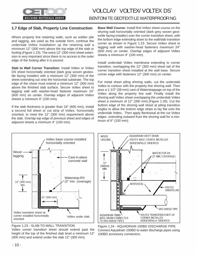
2.1 Property Line Wall Installation GuidelinesAfter the slab-to-wall corner transition sheet and bottomwall sheet course have been installed per Section 1.7Page 10, Voltex sheets can be installed either vertically orhorizontally oriented. Fasten the Voltex into position withwasher-head fasteners 24" (600 mm) on center aroundthe sheet edge. Install succeeding Voltex sheet overlap-ping the previous sheet edge 4" (100 mm). (Note: Shinglelap seams so that the bottom edge of the upper sheet isover the lower sheets top edge).
Continue installation up wall until finished grade elevation,or as specified, staggering all sheet ends of adjacent rollsa minimum 12" (300 mm). Do not allow sheet overlapjoints to occur at same elevation as concrete cold joints.Plan by chalk lining the location of construction joints.
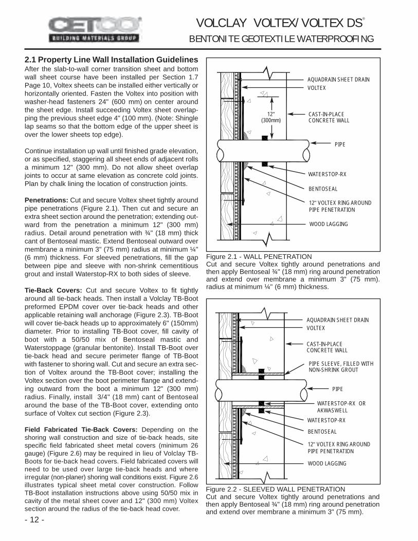
Penetrations: Cut and secure Voltex sheet tightly aroundpipe penetrations (Figure 2.1). Then cut and secure anextra sheet section around the penetration; extending out-ward from the penetration a minimum 12" (300 mm)radius. Detail around penetration with ¾" (18 mm) thickcant of Bentoseal mastic. Extend Bentoseal outward overmembrane a minimum 3" (75 mm) radius at minimum ¼"(6 mm) thickness. For sleeved penetrations, fill the gapbetween pipe and sleeve with non-shrink cementitiousgrout and install Waterstop-RX to both sides of sleeve.
Tie-Back Covers: Cut and secure Voltex to fit tightlyaround all tie-back heads. Then install a Volclay TB-Bootpreformed EPDM cover over tie-back heads and otherapplicable retaining wall anchorage (Figure 2.3). TB-Bootwill cover tie-back heads up to approximately 6" (150mm)diameter. Prior to installing TB-Boot cover, fill cavity ofboot with a 50/50 mix of Bentoseal mastic andWaterstoppage (granular bentonite). Install TB-Boot overtie-back head and secure perimeter flange of TB-Bootwith fastener to shoring wall. Cut and secure an extra sec-tion of Voltex around the TB-Boot cover; installing theVoltex section over the boot perimeter flange and extend-ing outward from the boot a minimum 12" (300 mm)radius. Finally, install 3/4" (18 mm) cant of Bentosealaround the base of the TB-Boot cover, extending ontosurface of Voltex cut section (Figure 2.3).
Field Fabricated Tie-Back Covers: Depending on theshoring wall construction and size of tie-back heads, sitespecific field fabricated sheet metal covers (minimum 26gauge) (Figure 2.6) may be required in lieu of Volclay TB-Boots for tie-back head covers. Field fabricated covers willneed to be used over large tie-back heads and whereirregular (non-planer) shoring wall conditions exist. Figure 2.6illustrates typical sheet metal cover construction. FollowTB-Boot installation instructions above using 50/50 mix incavity of the metal sheet cover and 12" (300 mm) Voltexsection around the radius of the tie-back head cover.
- 12 -
CAST-IN-PLACE CONCRETE WALL
WATERSTOP-RX
WOOD LAGGING
12" VOLTEX RING AROUNDPIPE PENETRATION
AQUADRAIN SHEET DRAINVOLTEX
PIPE
BENTOSEAL
Figure 2.1 - WALL PENETRATIONCut and secure Voltex tightly around penetrations andthen apply Bentoseal ¾" (18 mm) ring around penetrationand extend over membrane a minimum 3" (75 mm).radius at minimum ¼" (6 mm) thickness.
WATERSTOP-RX
WOOD LAGGING
AQUADRAIN SHEET DRAINVOLTEX
PIPE
BENTOSEAL
PIPE SLEEVE, FILLED WITHNON-SHRINK GROUT
WATERSTOP-RX ORAKWASWELL
12" VOLTEX RING AROUNDPIPE PENETRATION
Figure 2.2 - SLEEVED WALL PENETRATIONCut and secure Voltex tightly around penetrations andthen apply Bentoseal ¾" (18 mm) ring around penetrationand extend over membrane a minimum 3" (75 mm).
V O L C L AY V O LT E X / V O LT E X D S ®
B E N T O N I T E G E O T E X T I L E W AT E R P R O O F I N G
12"(300mm)
CAST-IN-PLACE CONCRETE WALL
4181 Voltex CIP_nl.qxp 1/10/2005 2:26 PM Page 12

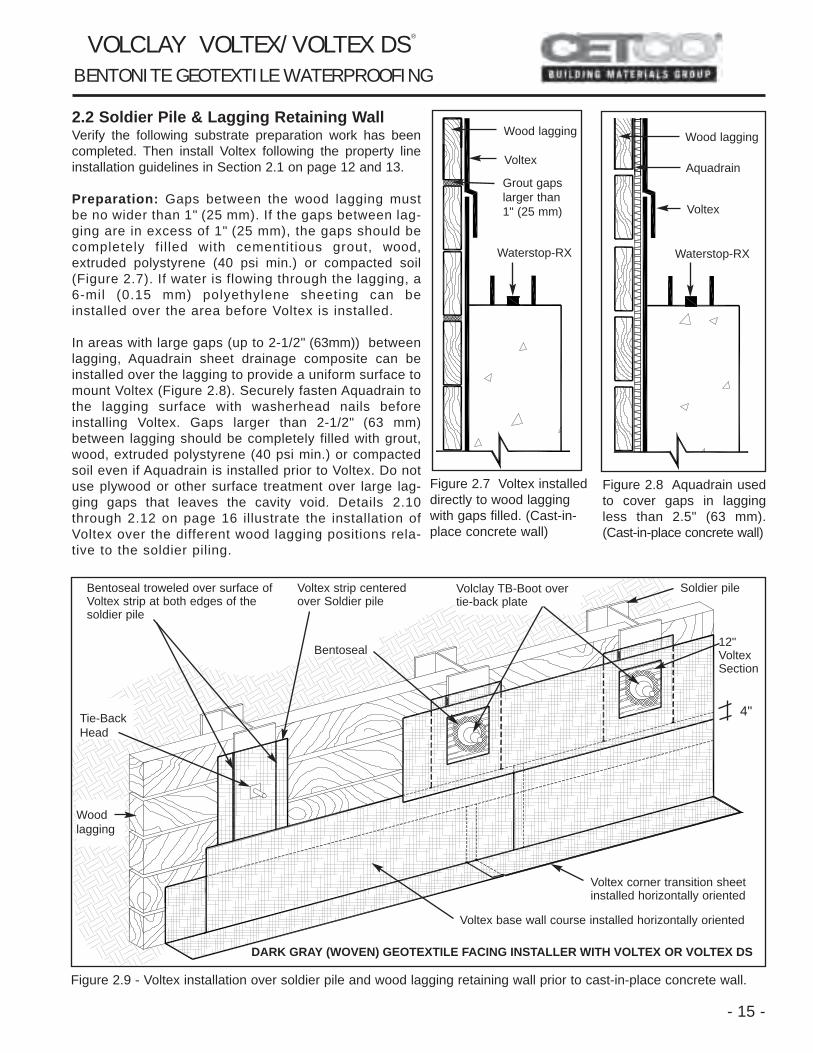
Soldier Pile Stripping: Install a strip of Voltex over all sol-dier piles with raised lagging hanger bolts, form tie rods,or other irregular surface. Voltex strip should extend aminimum 6" (150 mm) to both sides of the piling. ApplyBentoseal 1/4" x 2" (6mm x 50 mm) to Voltex stripsurface along both edges of each soldier pile(Figure 2.9).
Cementitious Board: Prior to installing Voltex/Voltex DSto finished grade, install ½" (12 mm) thick cementitiouswall board centered over steel soldier pile from finishedgrade elevation to specified depth that the top of steel sol-dier pile and wood lagging will be removed (Figure 2.13).
Grade Termination: Terminate Voltex at grade with a rigidtermination bar fastened 12" (300 mm) on center. A 12"(300 mm) wide strip of UV resistant flashing is recom-mended to be installed with the termination bar. Embedthe top edge of Voltex and termination bar in a 2" (50 mm)wide by 1/2" (12 mm) thick bead of Bentoseal. Note that itmay be necessary to dig and remove several pieces oflagging to facilitate the termination. See terminationdetails, Figure 3.11 and 3.12, Page 23.
- 13 -
FASTENER
FILL TB-BOOT CAVITY WITH50/50 MIX OF BENTOSEALAND WATERSTOPPAGEBEFORE PLACEMENT
WOOD LAGGINGAQUADRAIN SHEET DRAIN
12" VOLTEX SECTIONINSTALLED AROUND VOLCLAY TB-BOOT
VOLCLAY TB-BOOT, PREFORMED EPDM COVER
BENTOSEAL
VOLTEX
BENTOSEAL
TIE-BACK HEAD
Figure 2.3 - PREFORMED TB-BOOT COVERSInstall a Volclay TB-Boot preformed EPDM cover over tie-back heads and other applicable retaining wall anchor-age. Prior to installing, fill cavity of TB-Boot with a 50/50mix of Bentoseal and Waterstoppage (granular bentonite).
Figure 2.4 - VOLCLAY TB-BOOT TIE-BACK COVERTB-Boot installed over soldier pile tie-back head withBentoseal applied around the perimeter extending ontothe 12" Voltex ring section around the tie-back plate.
VOLCLAY TB-BOOT BENTOSEAL
Figure 2.5 - TB-BOOT CAVITY MIXFill TB-Boot cavity with 50/50 mix of Bentoseal andWaterstoppage prior to being installed.
V O L C L AY V O LT E X / V O LT E X D S ®
B E N T O N I T E G E O T E X T I L E W AT E R P R O O F I N G
4181 Voltex CIP_nl.qxp 1/10/2005 2:26 PM Page 13

- 14 -
Figure 2.6 - FIELD FABRICATED SHEET METAL TIE-BACK HEAD COVERS. Field fabricated galvanized sheet metal covers (26 gauge. min.) will need to be used over large tie-back heads andwhere irregular (non-planer) shoring wall conditions exist. Prior to installation, fill sheet metal cover cavity with 50/50 mixof Bentoseal and Waterstoppage (granular bentonite).
FIELD DIMENSIONPROVIDE 1/2" (12 mm) MIN. CLEARANCE BETWEEN TIE-BACKAND SHEET METAL COVER TOP
SHEET METAL COVER TOP
FILL COVER CAVITY WITH 50/50 MIX OF BENTOSEAL AND WATERSTOPPAGE(GRANULAR BENTONITE)
3" (75 mm) MIN.
3" (75 mm) MIN.
SHEET METAL SCREW
SHEET METAL FLANGE
SIDE SECTION VIEW OF GALVANIZED SHEET METAL COVER
FIELD FABRICATED SHEET METAL BOX ISTYPICALLY MADE OF TWO SHEET METALFORMS ILLUSTRATED ABOVE, FITTEDTOGETHER AT 90 DEGREES TO FORM ABOX AND THEN SCREWED TOGETHER.
AFTER ASSEMBLY, BOX CAVITY OFSHEET METAL COVER IS FILLED WITH50/50 MIX OF WATERSTOPPAGE (GRANU-LAR BENTONITE) AND BENTOSEALPRIOR TO INSTALLATION.
NOTE: SIZE OF SHEET METAL COVER WILL BEDETERMINED BY ACTUAL FIELD DIMENSIONS.PROJECT CONDITIONS MAY REQUIRE VARIEDSIZES TO COVER DIFFERENT CONDITIONS.
V O L C L AY V O LT E X / V O LT E X D S ®
B E N T O N I T E G E O T E X T I L E W AT E R P R O O F I N G
4181 Voltex CIP_nl.qxp 1/10/2005 2:26 PM Page 14
- 15 -
2.2 Soldier Pile & Lagging Retaining WallVerify the following substrate preparation work has beencompleted. Then install Voltex following the property lineinstallation guidelines in Section 2.1 on page 12 and 13.
Preparation: Gaps between the wood lagging mustbe no wider than 1" (25 mm). If the gaps between lag-ging are in excess of 1" (25 mm), the gaps should becompletely fi l led with cementitious grout, wood,extruded polystyrene (40 psi min.) or compacted soil(Figure 2.7). If water is flowing through the lagging, a6-mil (0.15 mm) polyethylene sheeting can beinstalled over the area before Voltex is installed.
In areas with large gaps (up to 2-1/2" (63mm)) betweenlagging, Aquadrain sheet drainage composite can beinstalled over the lagging to provide a uniform surface tomount Voltex (Figure 2.8). Securely fasten Aquadrain tothe lagging surface with washerhead nails beforeinstalling Voltex. Gaps larger than 2-1/2" (63 mm)between lagging should be completely filled with grout,wood, extruded polystyrene (40 psi min.) or compactedsoil even if Aquadrain is installed prior to Voltex. Do notuse plywood or other surface treatment over large lag-ging gaps that leaves the cavity void. Details 2.10through 2.12 on page 16 illustrate the installation ofVoltex over the different wood lagging positions rela-tive to the soldier piling.
Figure 2.7 Voltex installeddirectly to wood laggingwith gaps filled. (Cast-in-place concrete wall)
Figure 2.8 Aquadrain usedto cover gaps in laggingless than 2.5" (63 mm).(Cast-in-place concrete wall)
Figure 2.9 - Voltex installation over soldier pile and wood lagging retaining wall prior to cast-in-place concrete wall.
Wood lagging
Voltex
Grout gapslarger than 1" (25 mm)
Waterstop-RX Waterstop-RX
Voltex
Wood lagging
Aquadrain
Voltex corner transition sheetinstalled horizontally oriented
DARK GRAY (WOVEN) GEOTEXTILE FACING INSTALLER WITH VOLTEX OR VOLTEX DS
Voltex base wall course installed horizontally oriented
Woodlagging
Bentoseal troweled over surface ofVoltex strip at both edges of thesoldier pile
Voltex strip centeredover Soldier pile
V O L C L AY V O LT E X / V O LT E X D S ®
B E N T O N I T E G E O T E X T I L E W AT E R P R O O F I N G
Soldier pile
4"
Volclay TB-Boot overtie-back plate
Bentoseal
Tie-BackHead
12"VoltexSection
4181 Voltex CIP_nl.qxp 1/10/2005 2:26 PM Page 15

- 16 -
Figure 2.10 - Lagging secured to outside surface offront pile flange providing smooth surface (Plan View).
Figure 2.11 - Lagging secured to inside surface of frontpile flange. Install Voltex strip to cover mounting platesand bolts prior to main Voltex course (Plan View).
Figure 2.12 - Lagging secured to inside surface of backpile flange. Install Bentoseal and Voltex strip prior to mainVoltex course and inward Bentoseal cant (Plan View).
Steelpiling
Wood lagging
Voltex, main course
Waterstop-RX(min. 3" coverage)
Bentoseal
Steelpiling
Retained earth
Wood lagging
Voltex, main course
Bentoseal betweensheets of Voltex
Waterstop-RX
Cast-in-placeconcrete wall
V O L C L AY V O LT E X / V O LT E X D S ®
B E N T O N I T E G E O T E X T I L E W AT E R P R O O F I N G
Figure 2.13 - WALL EXCAVATION AT GRADECementitious board protects waterproofing during exca-vation and removal of steel pile top and wood lagging.
Aquadrain sheet drain
Voltex Cementitious board
Wood lagging
Steel H-Pile,top removedwith excavationwork
Wood Lagging
Voltex, main course
Waterstop-RX(min. 3" coverage)
Steelpiling
Rebar
Cast-in-placeconcrete wall
Voltex strip over pileprior to main course
Plate & boltssecure lagging
Fill gap with solidmaterial
Bentoseal, apply two cants - onebefore Voltex strip and one afterVoltex main course
Any void area mustbe filled with woodor solid material
Cast-in-placeconcrete wall
Voltex strip installedprior to main Voltexcourse
6"(150 mm)
Waterstop-RXto exterior ofcut rebar holein steel piling
Cast-in-placeconcrete wall
Voltex strip overpile prior to mainVoltex course
4181 Voltex CIP_nl.qxp 1/10/2005 2:26 PM Page 16
- 17 -
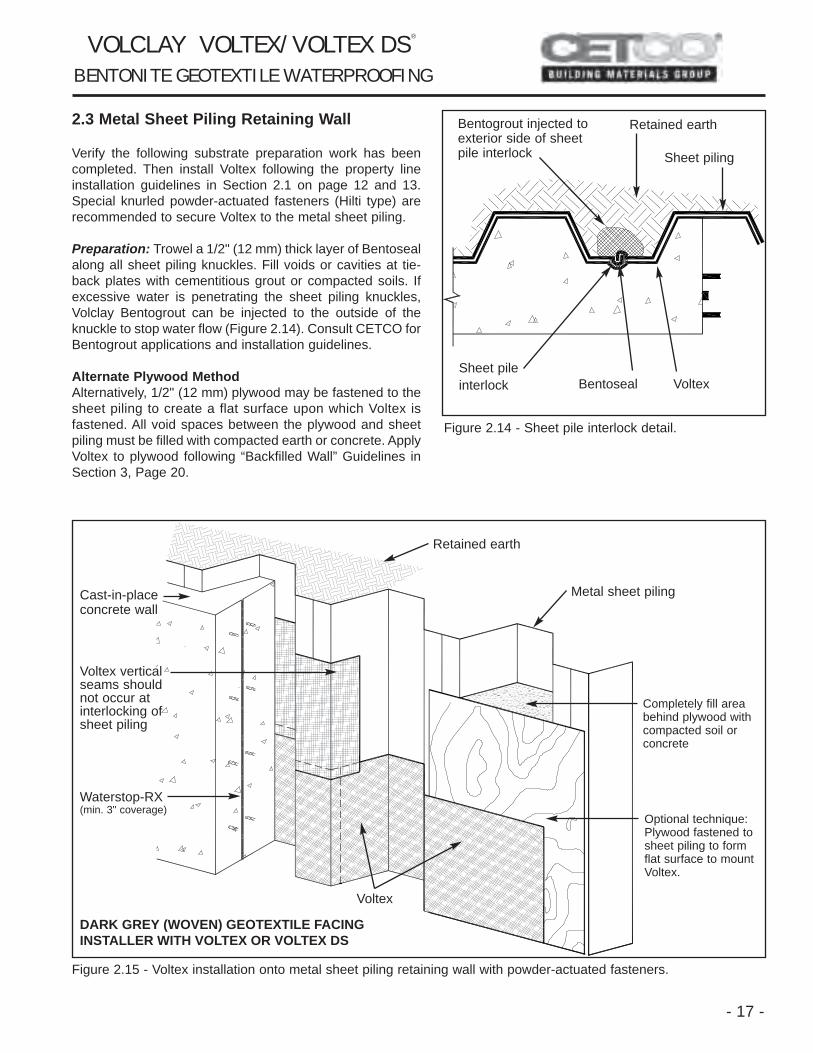
2.3 Metal Sheet Piling Retaining Wall
Verify the following substrate preparation work has beencompleted. Then install Voltex following the property lineinstallation guidelines in Section 2.1 on page 12 and 13.Special knurled powder-actuated fasteners (Hilti type) arerecommended to secure Voltex to the metal sheet piling.
Preparation: Trowel a 1/2" (12 mm) thick layer of Bentosealalong all sheet piling knuckles. Fill voids or cavities at tie-back plates with cementitious grout or compacted soils. Ifexcessive water is penetrating the sheet piling knuckles,Volclay Bentogrout can be injected to the outside of theknuckle to stop water flow (Figure 2.14). Consult CETCO forBentogrout applications and installation guidelines.
Alternate Plywood MethodAlternatively, 1/2" (12 mm) plywood may be fastened to thesheet piling to create a flat surface upon which Voltex isfastened. All void spaces between the plywood and sheetpiling must be filled with compacted earth or concrete. ApplyVoltex to plywood following “Backfilled Wall” Guidelines inSection 3, Page 20.
Figure 2.14 - Sheet pile interlock detail.
Figure 2.15 - Voltex installation onto metal sheet piling retaining wall with powder-actuated fasteners.
Bentoseal VoltexSheet pileinterlock
Bentogrout injected toexterior side of sheetpile interlock
Retained earth
Voltex verticalseams shouldnot occur atinterlocking ofsheet piling
Cast-in-placeconcrete wall
Waterstop-RX(min. 3" coverage)
DARK GREY (WOVEN) GEOTEXTILE FACINGINSTALLER WITH VOLTEX OR VOLTEX DS
Retained earth
Metal sheet piling
Completely fill areabehind plywood withcompacted soil orconcrete
Optional technique:Plywood fastened tosheet piling to formflat surface to mountVoltex.
Voltex
V O L C L AY V O LT E X / V O LT E X D S ®
B E N T O N I T E G E O T E X T I L E W AT E R P R O O F I N G
Sheet piling
4181 Voltex CIP_nl.qxp 1/10/2005 2:26 PM Page 17
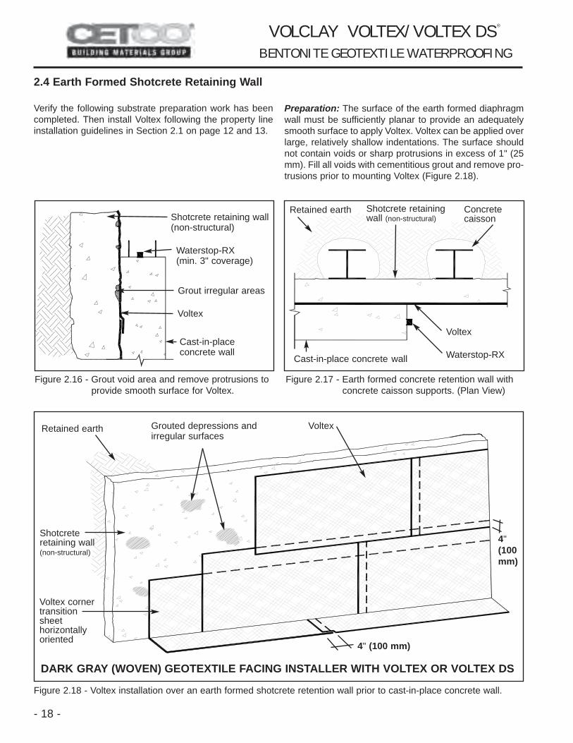
2.4 Earth Formed Shotcrete Retaining Wall
Verify the following substrate preparation work has beencompleted. Then install Voltex following the property lineinstallation guidelines in Section 2.1 on page 12 and 13.
Preparation: The surface of the earth formed diaphragmwall must be sufficiently planar to provide an adequatelysmooth surface to apply Voltex. Voltex can be applied overlarge, relatively shallow indentations. The surface shouldnot contain voids or sharp protrusions in excess of 1" (25mm). Fill all voids with cementitious grout and remove pro-trusions prior to mounting Voltex (Figure 2.18).
Figure 2.16 - Grout void area and remove protrusions toprovide smooth surface for Voltex.
Figure 2.17 - Earth formed concrete retention wall with concrete caisson supports. (Plan View)
Figure 2.18 - Voltex installation over an earth formed shotcrete retention wall prior to cast-in-place concrete wall.
- 18 -
Shotcrete retaining wall(non-structural)
Grout irregular areas
Voltex
Cast-in-place concrete wall
Retained earth Shotcrete retainingwall (non-structural)
Concretecaisson
Cast-in-place concrete wall Waterstop-RX
Voltex
Retained earth Grouted depressions andirregular surfaces
Voltex
4"(100mm)
4" (100 mm)
DARK GRAY (WOVEN) GEOTEXTILE FACING INSTALLER WITH VOLTEX OR VOLTEX DS
Shotcreteretaining wall(non-structural)
V O L C L AY V O LT E X / V O LT E X D S ®
B E N T O N I T E G E O T E X T I L E W AT E R P R O O F I N G
Voltex corner transitionsheethorizontallyoriented
Waterstop-RX(min. 3" coverage)
4181 Voltex CIP_nl.qxp 1/10/2005 2:26 PM Page 18
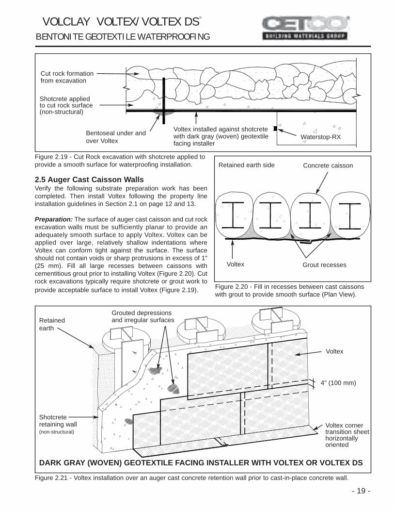
Figure 2.19 - Cut Rock excavation with shotcrete applied toprovide a smooth surface for waterproofing installation.
2.5 Auger Cast Caisson WallsVerify the following substrate preparation work has beencompleted. Then install Voltex following the property lineinstallation guidelines in Section 2.1 on page 12 and 13.
Preparation: The surface of auger cast caisson and cut rockexcavation walls must be sufficiently planar to provide anadequately smooth surface to apply Voltex. Voltex can beapplied over large, relatively shallow indentations whereVoltex can conform tight against the surface. The surfaceshould not contain voids or sharp protrusions in excess of 1"(25 mm). Fill all large recesses between caissons withcementitious grout prior to installing Voltex (Figure 2.20). Cutrock excavations typically require shotcrete or grout work toprovide acceptable surface to install Voltex (Figure 2.19). Figure 2.20 - Fill in recesses between cast caissons
with grout to provide smooth surface (Plan View).
Figure 2.21 - Voltex installation over an auger cast concrete retention wall prior to cast-in-place concrete wall.
- 19 -
Cut rock formationfrom excavation
Shotcrete appliedto cut rock surface(non-structural)
Bentoseal under andover Voltex
Voltex installed against shotcretewith dark gray (woven) geotextile facing installer
Waterstop-RX
Retained earth side Concrete caisson
Voltex Grout recesses
Grouted depressionsand irregular surfacesRetained
earth
Shotcrete retaining wall(non-structural)
DARK GRAY (WOVEN) GEOTEXTILE FACING INSTALLER WITH VOLTEX OR VOLTEX DS
Voltex
4" (100 mm)
V O L C L AY V O LT E X / V O LT E X D S ®
B E N T O N I T E G E O T E X T I L E W AT E R P R O O F I N G
Voltex corner transition sheethorizontally oriented
4181 Voltex CIP_nl.qxp 1/10/2005 2:26 PM Page 19

SECTION 3BACKFILLED WALLS
Install Voltex or Voltex DS with the dark gray (woven)geotextile side against the concrete wall on cast-in-place concrete foundation walls prior to backfilling. Voltexmay be applied as soon as the forms are removed. It isnot necessary to wait for the concrete to completely cure.Use Voltex with concrete cast with conventional forms thatproduce smooth surface.
3.1 Surface Preparation
Footing should be swept clean of silt, rocks and debris toprovide Voltex with direct contact to the concrete in theapplication area. The wall surface must be properly pre-pared before Voltex is installed. Areas of surface honey-combing or voids should be filled with cementitious groutor Bentoseal. Protrusions of over 1/4" (6 mm) should beknocked off smooth with the concrete surface. Concretework should include completely filling taper-tie holes withnon-shrink cementitious grout and a piece of Waterstop-RX centered in the wall (Figure 3.1). Apply Bentoseal overexterior grouted surface of all form tie holes (Figure 3.1).
3.2 Installation
Before installing the first course of Voltex, place HydrobarTubes at the wall/footing inside corner (Figure 3.2). “Butt”the ends of Hydrobar Tubes together to form a continuousline.
Beginning at the bottom corner of the wall, install Voltexhorizontally oriented with 5' (1.5 m) on one wall and theremainder around the corner on the other wall surface(Figure 3.2). Cut the bottom edge of Voltex at the corner aminimum of 6" (150 mm) so that Voltex can be extendedonto the footing. Fasten Voltex into position with washerhead fasteners. Then cut and install a Voltex section overthe uncovered footing corner area. Apply Bentoseal at theVoltex section to Voltex overlaps. (Figure 3.2).
Install adjacent Voltex rolls of the bottom course horizon-tally oriented. Each roll should overlap the preceding roll aminimum 4" (100 mm) and should extend onto the footinga minimum 6" (150 mm). At vertical inside cornersapply a continuous 3/4" (18 mm) fillet of Bentoseal direct-ly in the corner prior to installing Voltex (Figure 3.3).Stagger all vertical overlap joints a minimum of 12"(300 mm) (Figure 3.4). When hydrostatic conditions exist,the vertical wall Voltex should cover the entire footing andoverlap the underslab waterproofing a minimum 6" (150mm) (Figure 3.6).
Figure 3.1 - Concrete form tie details.
Figure 3.2 - Start Voltex at the corner horizontally. Placecut Voltex section at corner and apply Bentoseal.
Figure 3.3 - Apply fillet of Bentoseal to inside corner.
- 20 -
SNAP-TIE TAPER-TIE
Non-shrink grout
Concrete Tie Bentosealexterior faceof form tie
Non-shrink grout
HydrobarTube underVoltex
Install Voltex around corner
Voltex
BentosealCut Voltex section positioned at corner
Inside corner of cast-in-place concrete wall
Install Voltexto fit corner
3/4" (18 mm)Fillet ofBentoseal
V O L C L AY V O LT E X / V O LT E X D S ®
B E N T O N I T E G E O T E X T I L E W AT E R P R O O F I N G
Voltex
Waterstop-RX
4181 Voltex CIP_nl.qxp 1/10/2005 2:26 PM Page 20
- 21 -
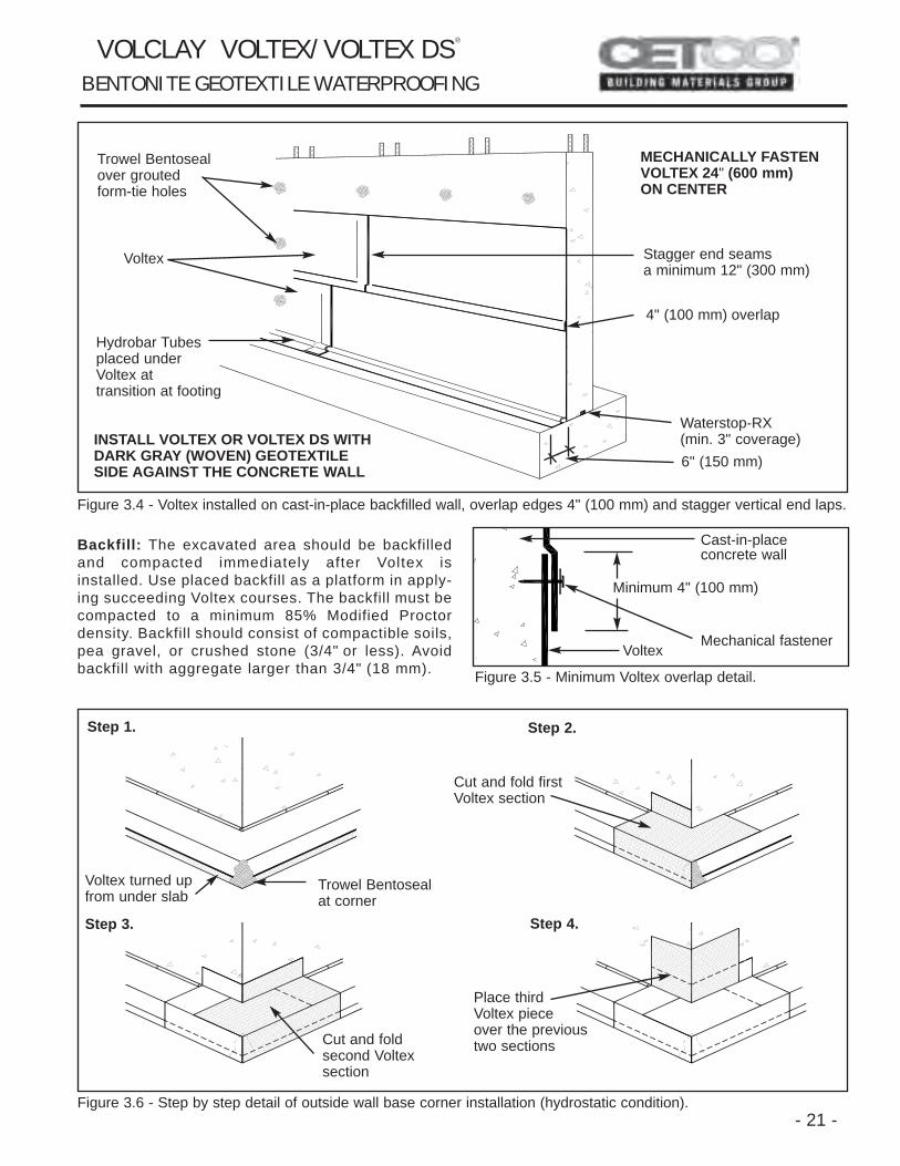
Figure 3.4 - Voltex installed on cast-in-place backfilled wall, overlap edges 4" (100 mm) and stagger vertical end laps.
Backfill: The excavated area should be backfilledand compacted immediately after Voltex isinstalled. Use placed backfill as a platform in apply-ing succeeding Voltex courses. The backfill must becompacted to a minimum 85% Modified Proctordensity. Backfill should consist of compactible soils,pea gravel, or crushed stone (3/4" or less). Avoidbackfill with aggregate larger than 3/4" (18 mm). Figure 3.5 - Minimum Voltex overlap detail.
Figure 3.6 - Step by step detail of outside wall base corner installation (hydrostatic condition).
INSTALL VOLTEX OR VOLTEX DS WITHDARK GRAY (WOVEN) GEOTEXTILESIDE AGAINST THE CONCRETE WALL
MECHANICALLY FASTENVOLTEX 24" (600 mm)ON CENTER
Trowel Bentosealover grouted form-tie holes
Voltex
4" (100 mm) overlap
Stagger end seams a minimum 12" (300 mm)
Waterstop-RX (min. 3" coverage)6" (150 mm)
Hydrobar Tubesplaced under Voltex at transition at footing
Cast-in-placeconcrete wall
Voltex Mechanical fastener
Minimum 4" (100 mm)
Step 1. Step 2.
Step 3. Step 4.
Voltex turned upfrom under slab
Trowel Bentoseal at corner
Cut and fold firstVoltex section
Place thirdVoltex pieceover the previoustwo sectionsCut and fold
second Voltex section
V O L C L AY V O LT E X / V O LT E X D S ®
B E N T O N I T E G E O T E X T I L E W AT E R P R O O F I N G
4181 Voltex CIP_nl.qxp 1/10/2005 2:26 PM Page 21

- 22 -
3.3 Backfilled Wall Penetrations
Cut Voltex to closely fit around penetrations. Afterinstalling Voltex, trowel a minimum 3/4" (18 mm) thick fil-let of Bentoseal around the penetration to completely fillany space between the penetration and the Voltex edge.The Bentoseal should extend onto the penetration 1-1/2"(38 mm) and cover Voltex’s edge (Figure 3.7). In areaswhere multiple penetrations are close together, it may beimpractical to cut Voltex to fit around base of each pene-tration. Therefore, apply a 3/4" (18 mm) thick fillet ofBentoseal around each penetration and cover the entiresurface between the penetrations (Figure 3.8). ExtendBentoseal 1-1/2" (38 mm) onto the penetrations.
Figure 3.8 - Cut Voltex to fit around multiple penetrations.
Figure 3.9 - Close multiple penetrations. Trowel Bentosealaround and between penetrations.
Figure 3.7 - Single penetration cast-in-place wall detail.
Figure 3.10 - Install Voltex between multiple penetrations with accessibility. Trowel Bentoseal around penetrations.
Voltex
Waterstop-RX(min. 3" coverage)
Pipe
Bentosealtroweled aroundpenetration
Voltex
Voltex cut out around multiple penetrations
Waterstop-RX
Voltex
Bentoseal
Pipe
Bentoseal
Pipe
Voltex
Waterstop-RX
Waterstop-RX
Voltex
Bentoseal
Pipe
Voltex
Bentoseal
Pipe
Voltex
Waterstop-RX
V O L C L AY V O LT E X / V O LT E X D S ®
B E N T O N I T E G E O T E X T I L E W AT E R P R O O F I N G
Bentoseal
Cast-in-placeconcrete wall
Apply Bentoseal to cut out area
4181 Voltex CIP_nl.qxp 1/10/2005 2:26 PM Page 22

-23-
3.4 Grade Terminations
Voltex should be brought up to the grade line on back-filled wall installations. Terminate Voltex at grade witha rigid metal termination bar fastened 12" (300 mm)on center. A 12" (300 mm) wide strip of UV resistantflashing is recommended to be installed with the ter-mination bar at grade level (Figure 3.11). Embed thetop edge of the Voltex and termination bar in 2" (50mm) wide, 1/2" (12 mm) thick bead of Bentoseal.Grade terminations are illustrated in Figures 3.11 and3.12.
3.5 Masonry Block Walls
Voltex is not recommended for waterproofing masonryblock walls. Consult with CETCO regarding recom-mended products and installation guidelines for masonryblock walls.
5.1 Precast Concrete ConstructionConsult CETCO regarding recommended products andspecial installation guidelines for precast concrete plankdecks, precast earth covered roofs, and precast wallconstruction.
5.2 Contaminated ConditionsUse Voltex CR (Contaminant Resistant) in conditionswhere the groundwater contains high concentrations ofchemicals or saline. These conditions are typicallyencountered at industrial sites and coastal regions. Ifgroundwater contains strong acids, alkalies, or has aconductivity of 2,500 µmhos/cm or greater (high salt con-centration), water samples should be submitted toCETCO for compatibility testing.
For compatibility testing, provide one quart (one liter) ofsite groundwater in a clean, unbreakable container. Shipwater sample to: CETCO Technical Center, 1500 WestShure Drive, Arlington Heights, IL 60004 - Attn: BuildingMaterials Group. Upon analysis, CETCO will provide awritten report evaluating the water’s compatibility withVoltex and recommend any special product and/orinstallation requirements.
5.3 High Hydrostatic Pressure ConditionsIf hydrostatic head pressure exceeds 33 feet (10 m)consult CETCO for installation recommendations andguidelines that may apply.
Figure 3.11 - Termination at finished grade.
Figure 3.12 - Termination at grade using through wallmetal flashing with brick veneer.
IMPORTANT NOTICEFOR SHOTCRETE, PRECAST CONCRETE,AND OTHER APPLICATIONS NOT COVEREDIN THIS MANUAL, CONTACT CETCO FORTECHNICAL ASSISTANCE AND INSTALLA-TION GUIDELINES.
SECTION 5SPECIAL CONDITIONS
Finished grade
Bentoseal or M-2000
Metal termination bar
12" wide UV resistant membrane (optional)
Voltex
Brick veneer
Weep hole
Finished grade
Through wall flashing
Voltex
V O L C L AY V O LT E X / V O LT E X D S ®
B E N T O N I T E G E O T E X T I L E W AT E R P R O O F I N G
Bentoseal or M-2000
Cast-in-place concrete wall
4181 Voltex CIP_nl.qxp 1/10/2005 2:26 PM Page 23

1500 West Shure DriveArlington Heights, IL 60004 USA(800)527-9948 Fax:(847)506-6195
www.cetco.com
The information and data contained herein is believed to be accurate and reliable.Specifications and other information contained herein supersede all previouslyprinted material and are subject to change without notice.
Manufacturer’s warranty of installed system is available. Contact seller for termsand sample documents including all limitations.
All goods sold by seller are warranted to be free from defects in material andworkmanship.
The foregoing warranty is in lieu of and excludes all other warranties not expresslyset forth herein, whether expressed or implied by operation of law or otherwiseincluding but not limited to any implied warranties of merchantability or fitness.
Seller shall not be liable for incidental or consequential losses, damages orexpenses, directly or indirectly arising from the sale, handling or use of the goods,or from any other cause relating thereto, and seller’s liability hereunder in any case
is expressly limited to the replacement (in the form originally shipped) of goods notcomplying with this agreement or at seller’s election, to the repayment of, orcrediting buyer with, an amount equal to the purchase price of such goods, whethersuch claims are for breach of warranty or negligence.Any claim by buyer with reference to the goods sold hereunder for any cause shall
be deemed waived by buyer unless submitted to seller in writing within thirty (30)days from the date buyer discovered or should of discovered, any claimed breach.
Materials should be inspected and tested by purchaser prior to their use ifproduct quality is subject to verification after shipment. Performance guaranteesare normally supplied by the applicator.
Note: Volclay Voltex/Voltex DS waterproofing system is not an expansion jointmaterial. Expansion joints shall be the responsibility of Others.
LIMITED WARRANTY
(SUPERSEDES ALL PREVIOUS VERSIONS)
© 2004, CETCO Form: VT 01/08 Printed in USA
PRODUCT
VOLTEX
VOLTEX CCR
VOLTEX DDS
VOLTEX DDSCR
IMPORTANT NOTICE CONTACT CETCO FOR VERIFICATION OF SPECIFICATION AND INSTALLATION REQUIRE-MENTS TO COMPLY WITH ISSUANCE OF VOLCLAY WATERPROOFING WARRANTY.
PRODUCT TABLE
DESCRIPTION
Bentonite Geotextile Waterproofing Membranewith standard Volclay sodium bentonite
Bentonite Geotextile Waterproofing Membranewith contaminant resistant sodium bentonite
Bentonite Geotextile Waterproofing Membranewith standard Volclay sodium bentonite and apolyethylene liner component
Bentonite Geotextile Waterproofing Membranewith contaminant resistant sodium bentoniteand a polyethylene liner component
ROLL SIZE
4-FT x 15-FT (1.2 m x 4.5 m)
4-FT x 15-FT (1.2 m x 4.5 m)
4-FT x 14.5-FT (1.2 m x 4.4 m)
4-FT x 14.5-FT (1.2 m x 4.4 m)
4181 Voltex CIP_nl.qxp 1/10/2005 2:26 PM Page 24
004
JANUARY 2008