POWER OPTIMISATION - Voltex
48
your elec t rical connec t ion POWER OPTIMISATION www.voltex.co.za Version – PO SF 1
Transcript of POWER OPTIMISATION - Voltex
your electrical connection
POWER OPTIMISATION
www.voltex.co.za Version – PO SF 1

Index
• ACTIVAR
• EQUALIZER
• EQUALIZER-ST
4
8
17
• G4500/G3500 Portable Power Quality Analyser BLACKBOX 28
• PQSCADA Power Quality Management Suite 33
• G4K Fixed Power Quality Analyser BLACKBOX 36
• Digital Fault Recorder (DFR) BLACKBOX 40
4.2.5 Consistent Capacity Pg84.2.5 Ideal PFC Control Pg84.2.9 Ideal PFC Control Pg84.2.7 Ideal PFC Control Pg8*4.2.3 The EQUALIZER Power Quality Solution Pg94.2.5 The EQUALIZER Power Quality Solution Pg94.2.10 The EQUALIZER Power Quality Solution Pg94.2.7 The EQUALIZER Power Quality Solution Pg94.2.7 Voltage Flickering Pg94.2.5 Harmonics (Non Linear Loads) Pg94.2.7 Adverse Effects of Slower Response Systems Pg104.2.7.9 Welding Machines Pg104.2.7.9 Electric Trains Pg114.2.5 Other Industrial Loads Pg124.2.9 Other Industrial Loads Pg124.2.9 Motor Start-up Pg114.2.5 Harmonics Filtration Pg114.2.9 Harmonics Filtration Pg11*4.2.3 Harmonics Filtration Pg11
4.2.5 Tuned EQUALIZER vs Active Harmonics Filters Pg54.2.5 The Controller Pg124.2.5 Power IQ Pg9*4.2.3 Accurate Fault-Location Algorithm
(BLACKBOX DFR) Pg414.2.9 Extended Web Interface (BLACKBOX DFR) Pg41 4.2.10 Extended Web Interface (BLACKBOX DFR) Pg41*4.2.3 Product Selection Pg43*4.2.5 Real-Time Measurements
(Power Quality Analyser BLACKBOX) Pg394.2.3 Optional Accessories
(Power Quality Analyser BLACKBOX) Pg304.2.5.7 No Missed Events
(Portable Power Quality Analyser BLACKBOX) Pg294.2.9 The Electrical Challenge (EQUALIZER-ST) Pg184.2.9 Mitigation Voltage Sags Pg194.2.9 Table Pg204.2.9 Table Pg23
POWER QUALITY SOLUTIONS
POWER QUALITY METERING AND MONITORING
VOLTAGE CHARACTERISTICS, COMPATIBILITY LEVELS, LIMITS AND ASSESSMENT METHODS
(Reference: NRS 048-2:2003)

POWER QUALITY SOLUTIONS
Power Factor CorrectionElectronics Switching (1 - 4 Seconds)
Full Compensation
ACTIVAR
EQUALIZER-ST
EQUALIZER
Power Factor CorrectionElectronics Switching (1 - 4 Seconds)Full Compensation
Power Factor CorrectionElectronics Switching >20 Milliseconds
Full CompensationDesigned Motor Start Optimisation

2 VOLTEX CATALOGUEFor extended & complete range visit www.voltex.co.za. Minimum quantity orders may apply. Dimensions generally shown in mm and subject to technical change. Voltex codes and descriptions have been used above. Use Voltex K8 codes and product type for spec purposes. Refer to appendix for additional information, certification required and full technical specification from the supplier. All details provided are for indicative purposes only. Complete T & C's at back of catalogue.4 VOLTEX CATALOGUE
POWER QUALITY SOLUTIONS
ACTIVAR
Fast and Accurate Compensation
Elspec ACTIVAR vs Electromechanically-Switch Capacitors
Simultaneous Group Connection
Transient-free Switching
Fixed Capacity and Filter Characteristics
Long Life and Reduced Maintenance Costs
Capacitor Duty Cycle - SCAN Mode
Easy-to-Use and Maintain
Low-Cost Solution
Slow Compensation Time
Single-Step Connection
Transients
Capacity Drop and Filter Variance
Limited Life and High Maintenance Costs
Unequal Duty Cycle
The ACTIVAR achieves full compensation in 1 second typical (3 - 4 seconds maximum). The compensation is based on averaging the FFT analysis of each cycle, resulting in more accurate compensation, even with the presence of harmonics.
When load changes require connection or disconnection of more than one step, the ACTIVAR controls the switching of as many steps as required at precisely the same time. Simultaneous connection or disconnection provides the following benefits:• Faster full compensation.• For example, a 1:2:2 system configuration and groups 1 and 2 are
connected. When 1 more step is required, group 3 will be connected simultaneously while group 1 is disconnected.
• Real binary sizing – 1:2:2 is exactly the same as 1:1:1:1:1.
Electronic switching technology prevents any transients typically associated with conventional capacitor switching. This is extremely important in sites with sensitive electronic equipment, such as hospitals, data centers and facilities.
The capacity of the ACTIVAR capacitors is virtually permanent over the years, which prevents the need to replace capacitors. Moreover, the tuning frequency remains constant over time, which allows system performance to remain at the highest possible level.
Elspec ACTIVAR reduces site maintenance costs by increasing the lifetime of:• Switching elements• Capacitors• Sensitive electronic equipment
The unique SCAN feature protects the ACTIVAR’s capacitors, reduces their average current and temperature and extends their life. Simultaneous connection and disconnection of steps in FIFO (First In First Out) manner is shown on the right.
Contactors have a finite and limited life, and therefore need to be replaced frequently. Transients caused by contactor switching and capacity degradation over time requires repetitive equipment failures and expensive replacements.
Groups in most conventional systems are engaged dependent on the actual load, but are not equally utilised. The first step generally gets the most usage and is the first to fail due to its high duty cycle compared to the other steps.
The advanced DSP and microprocessor-based controller, with its large full graphic LCD display, provide easy-to-use operation. The controller includes a complete electrical measurement system, which can replace a facilities’ main monitoring meter. The controller operates the BIT (Built In Test), which reports system or network conditions. The optional PowerIQ software can remotely control all ACTIVAR operation and display additional system power information.
The initial cost of the ACTIVAR system is slightly higher than traditional electro-mechanically-switched solutions. However, when the costs of operating and maintaining a traditional system (contactor and capacitor replacements and/or possible equipment damage) are added, the ACTIVAR’s overall costs are far less than an electro-mechanical system.
A significant time period elapses between connection or disconnection of a step. As a result, the performance of the compensation system is reduced due to the following:• Slower compensation, especially when more than one step is
required.• For example, a 1:2:2 system configuration and groups 1 and 2 are
connected. When 1 more step is required, group 3 will be connected long after group 1 is disconnected.
• Binary sizing affects performance.
Contactor-based switching causes significant current and voltage transients. These spikes can cause severe electrical damage and is one of the leading causes of power supply failure.
The capacity degrades over time and may require replacement of capacitors. Further, the (de-)tuned filters dependent on capacitor-inductor ratings. As the capacitors degrade over time, the (de-)tuning frequency will change, and may create a resonance condition, even though the original system included
harmonic inductors.
Due to technology limitations, electromechanical switching has slow compensation time. Connecting 1 step in 10 – 30 seconds, and complete compensation can take several minutes
Complicated Use and Maintenance
Low-Cost Solution
Electromechanical controllers normally require dip-switch programming and/or hard-to-follow programming manuals. Small
display monitoring (or none at all) makes it very difficult to examine system performance. Usually, an additional meter is required to check the network power parameters. The option for remote communication and control does not exist.
The initial cost of an electro-mechanical system quickly changes due to the component replacement and repair. When evaluating electromechanical switching over a period of time, the actual costs and indirect losses become much higher than the initial investment.
1 2 3 4 5 6
6
5
4
3
2
1
3VOLTEX CATALOGUEFor extended & complete range visit www.voltex.co.za. Minimum quantity orders may apply. Dimensions generally shown in mm and subject to technical change. Voltex codes and descriptions have been used above. Use Voltex K8 codes and product type for spec purposes. Refer to appendix for additional information, certification required and full technical specification from the supplier. All details provided are for indicative purposes only. Complete T & C's at back of catalogue. 5VOLTEX CATALOGUE
POWER QUALITY SOLUTIONS
ACTIVAR
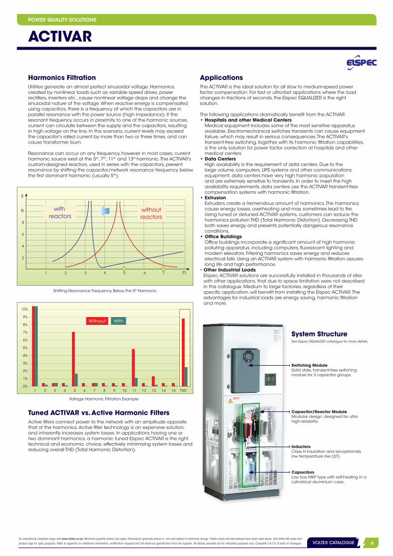
Harmonics FiltrationUtilities generate an almost perfect sinusoidal voltage. Harmonics, created by nonlinear loads such as variable speed drives, power rectifiers, inverters etc., cause nonlinear voltage drops and change the sinusoidal nature of the voltage. When reactive energy is compensated using capacitors, there is a frequency at which the capacitors are in parallel resonance with the power source (high impedance). If the resonant frequency occurs in proximity to one of the harmonic sources, current can circulate between the supply and the capacitors, resulting in high voltage on the line. In this scenario, current levels may exceed the capacitor's rated current by more than two or three times, and can cause transformer burn.
Resonance can occur on any frequency, however in most cases, current harmonic source exist at the 5th, 7th, 11th and 13th harmonic. The ACTIVAR's custom-designed reactors, used in series with the capacitors, prevent resonance by shifting the capacitor/network resonance frequency below the first dominant harmonic (usually 5th).
Tuned ACTIVAR vs. Active Harmonic Filters
Applications
Active filters connect power to the network with an amplitude opposite that of the harmonics. Active filter technology is an expensive solution, and inherently increases system losses. In applications having one or two dominant harmonics, a harmonic tuned Elspec ACTIVAR is the right technical and economic choice, effectively minimising system losses and reducing overall THD (Total Harmonic Distortion).
The ACTIVAR is the ideal solution for all slow to medium-speed power factor compensation. For fast or ultra-fast applications where the load changes in fractions of seconds, the Elspec EQUALIZER is the right solution.
The following applications dramatically benefit from the ACTIVAR:• Hospitals and other Medical Centers
Medical equipment includes some of the most sensitive apparatus available. Electromechanical switches transients can cause equipment failure, which may result in serious consequences. The ACTIVAR's transient-free switching, together with its harmonic filtration capabilities, is the only solution for power factor correction at hospitals and other medical centers.
• Data Centers High availability is the requirement of data centers. Due to the large volume computers, UPS systems and other communications equipment, data centers have very high harmonic population and are extremely sensitive to transients. In order to meet the high availability requirements, data centers use the ACTIVAR transient-free compensation systems with harmonic filtration.
• Extrusion Extruders create a tremendous amount of harmonics. The harmonics cause energy losses, overheating and may sometimes lead to fire. Using tuned or detuned ACTIVAR systems, customers can reduce the harmonics pollution THD (Total Harmonic Distortion). Decreasing THD both saves energy and prevents potentially dangerous resonance conditions.
• Office Buildings Office buildings incorporate a significant amount of high harmonic polluting apparatus, including computers, fluorescent lighting and modern elevators. Filtering harmonics saves energy and reduces electrical bills. Using an ACTIVAR system with harmonic filtration assures long life and high performance.
• Other Industrial Loads Elspec ACTIVAR solutions are successfully installed in thousands of sites with other applications, that due to space limitation were not described in this catalogue. Medium to large factories, regardless of their specific application, will benefit from installing the Elspec ACTIVAR. The advantages for industrial loads are energy saving, harmonic filtration and more.
Shifting Resonance Frequency Below the 5th Harmonic
System Structure
Switching ModuleSolid state, transient-free switching module for 3 capacitor groups.
Capacitor/Reactor ModuleModular design, designed for ultra high-reliability.
InductorsClass H insulation and exceptionally low temperature rise (∆T)
CapacitorsLow loss MKP type with self-healing in a cylindrical aluminium case.
Voltage Harmonic Filtration Example
See Elspec EQUALIZER catalogue for more details

2 VOLTEX CATALOGUEFor extended & complete range visit www.voltex.co.za. Minimum quantity orders may apply. Dimensions generally shown in mm and subject to technical change. Voltex codes and descriptions have been used above. Use Voltex K8 codes and product type for spec purposes. Refer to appendix for additional information, certification required and full technical specification from the supplier. All details provided are for indicative purposes only. Complete T & C's at back of catalogue.6 VOLTEX CATALOGUE
ACTIVARComplete System Ordering Information
System Type Total Power Step Size Number of
GroupsNominalVoltage
NominalFrequency
ReactorsPercentage
NetworkTypology
GroupProtection
CableConnection
CableEntry
AR 1440 120 12 400 50 P7 W F C A
System Type AR ACTIVAR Complete System
Total Power Total power in kVAr
Step Size Step size in kVAr (Switching Resolution)
Number of Groups Number of Groups (Physical, max. 12)
Nominal Voltage Nominal Phase-to-Phase Voltage in Volts
Nominal Frequency Nominal Frequency in Hz (50 or 60 Hz)
Reactors PercentageP0 Inrush Limiting Reactors Only
P# Percents of Capacity. Example: P7 = 7%.
Network Typology
D Delta 3 Wires
W Wye 4 Wires
V Wye 3 Wires
S Single phase
Group ProtectionF Groups protected by Fuses
M Groups protected by MCCBs
Cable Connection
C Single Point with Integral Circuit Breaker
S Single Connection Point
M Multiple Connection Points
Cable Entry
T Top Cable Entry
B Bottom Cable Entry
A Top and Bottom Cable Entry
L Left-Side Cable Entry
R Right-Side Cable Entry
%System Size Output kVAr Unit Dimensions
Cable Entry Product Code(kVAr) (Per Step) (cm)
7% 210 30 210 x 80 x 60 Top and Bottom L5598
7% 250 50 210 x 80 x 60 Top and Bottom L5599
7% 300 60 210 x 80 x 60 Top and Bottom L5600
7% 360 50 210 x 100 x 60 Top and Bottom L5602
7% 420 60 210 x 100 x 60 Top and Bottom L5605
7% 540 50 210 x 100 x 80 Top and Bottom L5608
7% 660 60 210 x 100 x 80 Top Only L5610
7% 780 120 210 x 160 x 60 Top and Bottom L5614
Example: AR 300:60:3-400.50-P7-WFSA 300kVAr transient-free complete ACTIVAR system with 5 steps of 60kVAr with 7% inductors, for 400V/50Hz 4-wires Wye network. Dimensions (W x D x H): 800 x 600 x 2100, Short Circuit 35kA, IP20.
Controller Type ACR ACTIVAR Controller
Measurement Level
1
2
3
Number of Groups Number of Groups (Physical, two digits, maximum 12)
Communication Card
0 No Communication
1 RS 485 ELCOM Protocol
2 RS 485 ELCOM and MODBUS/RTU Protocols
Power Supply1 115V
2 230V
Special TypeSee Controller section in the EQUALIZER
Up to two types can be combined
Controller Ordering Information
Controller Type Measurement Level Number of Groups Communication Card Power Supply Special Type
ACR 3 12 2 2 UT
POWER QUALITY SOLUTIONS

3VOLTEX CATALOGUEFor extended & complete range visit www.voltex.co.za. Minimum quantity orders may apply. Dimensions generally shown in mm and subject to technical change. Voltex codes and descriptions have been used above. Use Voltex K8 codes and product type for spec purposes. Refer to appendix for additional information, certification required and full technical specification from the supplier. All details provided are for indicative purposes only. Complete T & C's at back of catalogue. 7VOLTEX CATALOGUE
ACTIVARSpecifications
Measured Parameters
Parameter PhasesMeasurement Level
1 2 3
Frequency Common Mains • • •
Phase Current L1, L2, L3 Mains, Load, Cap. • • •
Neutral Current Neutral Mains • • •
Phase to Phase Current* L1-2, L2-3, L3-1 Mains, Load • • •
Phase Voltage L1, L2, L3 Mains • • •
Neutral Voltage Neutral Mains • • •
Phase to Phase Voltage L1-2, L2-3, L3-1 Mains • • •
Active Power (kW) L1, L2, L3, Total Mains • • •
Reactive Power (kVAr) L1, L2, L3, Total Mains, Load, Cap. • • •
Apparent Power (kVA) L1, L2, L3, Total Mains, Load, Cap. • • •
Power Factor L1, L2, L3, Total Mains, Load, Cap. • • •
Time of Use (TOU) - in, out, net, total:
Active Energy (kWh) Total Mains • •
Reactive Energy (kVARh) Total Mains • •
THD at Phase Current L1, L2, L3 Mains, Load, Cap. • •
THD at Neutral Current Neutral Mains • •
THD at Phase to Phase Current L1-2, L2-3, L3-1 Mains, Load • •
THD at Phase Voltage L1, L2, L3 Mains • •
THD at Neutral Voltage Neutral Mains • •
THD at Phase to Phase Voltage L1-2, L2-3, L3-1 Mains • •
Harmonics of Phase Current L1, L2, L3 Mains, Load, Cap. •
Harmonics of Neutral Current Neutral Mains •
Harmonics of Phase to Phase Current L1-2, L2-3, L3-1 Mains, Load •
Harmonics of Phase Voltage L1, L2, L3 Mains •
Harmonics of Neutral Voltage Neutral Mains •
Harmonics of Phase to Phase Voltage L1-2, L2-3, L3-1 Mains •
Waveforms of Phase Current L1, L2, L3 Mains, Load, Cap. •
Waveforms of Neutral Current Neutral Mains •
Waveforms of Phase to Phase Current L1-2, L2-3, L3-1 Mains •
Waveforms of Phase Voltage L1, L2, L3 Mains •
Waveforms of Neutral Voltage Neutral Mains •
Waveforms of Phase to Phase Voltage L1-2, L2-3, L3-1 Mains •
System Log • • •
Event Log • • •
* Unique feature: metering internal current of feeder transformer (delta secondary).
• Low Voltage Systems: 220V - 690V 50 or 60 Hz Single phase or three-phase
• Medium Voltage Systems: Up to 69kV 50 or 60Hz
• Ambient Temperature: + 40ºC: max (< 8 hours) + 35ºC: max 24 hours average + 20ºC: yearly average - 10ºC: minimum
• Capacitors: Low loss, self healing, IEC 831-1/2
• Protection Class: IP20/NEMA 1 (Other on request)
• Controller Display: 5” Graphic LCD 160 x 128 pixels High visibility (FSTN) Durable LED Backlight
• Design: Steel sheet cabinet
• Enclosure Finish: Epoxy powder coated Gray (RAL 7032)
• Internal Parts: Rust-proof alu-zinc
• EMC Standards: EN 50081-2, EN 50082-2 EN 55011, EN 61000-4-2/3/4/5 ENV 50204, ENV 50141
• Safety Standards: EN 61010-1, EN 60439-1 UL 508 (on request)
POWER QUALITY SOLUTIONS

2 VOLTEX CATALOGUEFor extended & complete range visit www.voltex.co.za. Minimum quantity orders may apply. Dimensions generally shown in mm and subject to technical change. Voltex codes and descriptions have been used above. Use Voltex K8 codes and product type for spec purposes. Refer to appendix for additional information, certification required and full technical specification from the supplier. All details provided are for indicative purposes only. Complete T & C's at back of catalogue.8 VOLTEX CATALOGUE
EQUALIZER Technology
Capacitor Group Switching
The EQUALIZER switches capacitor groups on and off using state-of-the-art electronic switches. The connection and disconnection of capacitors occur precisely at zero-current crossing. This smooth connection avoids transient effects typically created by electromechanically switched power factor correction (PFC) systems, extending the life expectancy of the EQUALIZER dramatically.
SCAN Mode
The EQUALIZER is equipped with a unique SCAN feature that protects capacitors from exploding and contributes to longer life expectancy by reducing over-current and minimising capacitor heating. The electronic switching element (unlimited operations) connects one capacitor group simultaneously as another group is disconnected. This operation occurs every few seconds, engaging each capacitor group in turn, with total compensation unchanged. This results in mean current reduction due to lower duty cycle (engagement time to cycle time). Together with the unique reactor design, temperature rise of the reactors is substantially reduced and the potential for cabinet overheating is minimised.
Consistent Capacity
Conventional electromechanical capacitor banks suffer from an ongoing cumulative reduction in capacity due to the effect of transients during connection and disconnection. This can be especially detrimental in tuned and detuned electromechanically switched systems where changes in the ratio between the capacitors and reactors shift the resonant frequency. This scenario can cause resonance, which can cause extreme damage to equipment in the facility. The EQUALIZER prevents this scenario, resulting in longer system life, lower maintenance costs and more consistent harmonic filtration over time.
Ideal PFC Control
Using exclusive automatic control algorithms and rapid electronic switching, total acquisition time (complete compensation of reactive current) is achieved in cycle typical ¼ - 1 cycle max.; (50Hz = 13.3 ms; 60Hz = 11.1 ms), irrespective of the number of steps required.The power factor is controlled very accurately through an advanced open and closed-loop control and measuring system that uses information from all three phases, as well as accounts for the effect of harmonics (1 through 63). Minimum, maximum and average power factor modes, as well as threshold levels, can be selected for perfect compliance with specific network requirements. The EQUALIZER includes a unique solution for line-to-line loads, in which it calculates a transformer’s internal currents and compensates accordingly. Third party measurements have proven the EQUALIZER to be the ultimate solution to offer precise compensation for voltage drop and flickering.
1 2 3 4 5 6
6
5
4
3
2
1
Group
3 groups are always engaged
Each group is engaged50% of the time
Time
The Controller
2- and 3-Phase Switching Structure
L2 L3L1 L2 L3L1L2 L3L1 L2 L3L1
Electromechanical vs. Transient-free Switching 1 Group Switching Module
THE EQUALIZER
Scan Mode
POWER QUALITY SOLUTIONS

3VOLTEX CATALOGUEFor extended & complete range visit www.voltex.co.za. Minimum quantity orders may apply. Dimensions generally shown in mm and subject to technical change. Voltex codes and descriptions have been used above. Use Voltex K8 codes and product type for spec purposes. Refer to appendix for additional information, certification required and full technical specification from the supplier. All details provided are for indicative purposes only. Complete T & C's at back of catalogue. 9VOLTEX CATALOGUE
POWER QUALITY SOLUTIONS
THE EQUALIZER
The EQUALIZER Power Quality Solution
Power IQ Measurement & Analysis Software (optional)
This Windows-based software can display the system’s status, measurement results and real-time data.
Definition
Power Quality is a term used to define any occurrence of voltage, current or frequency deviation that results in equipment failure, process interruptions or power system inefficiency. These deviations can manifest themselves in harmonics, power factor, voltage sags/swells, voltage flickering, transients and many other forms. The EQUALIZER from Elspec is an all-in-one solution for power quality problems, typically installed near the main service and near major distribution panels.
Voltage Sags (Voltage Drops, Under-Voltage)
Voltage sags, also known as voltage drops or under-voltage, are caused by local loads, either during motor startup or from rapidly changing loads. This condition is characterised by low power factor and high reactive energy demand. The Elspec EQUALIZER’s ultra-fast technology is designed to act in these specialised conditions. It connects all required capacitor banks in cycle typical (¼ - 1 cycle max.), compensating for the total reactive energy of the event. Moreover, it changes the direction of the voltage drop vector to minimise the sag. As a result, the voltage sag is minimised and in many cases, even eliminated (Please see Motor Startup and Elevator in the application section).
Voltage Flickering
Voltage flickering is caused by fast voltage fluctuations commonly associated with rapid loads, such as spot welders. The EQUALIZER’s control technology connects and disconnects all required capacitor banks in cycle typical (¼ - 1 cycle max.), effectively reducing the flicker to acceptable levels (Please see Spot Welding in the application section).
Power Factor
In many cases, low power factors result in higher utility bills through penalties and increased demand charges. They also cause system energy losses, overheating, increased maintenance costs and low service utilisation. The Elspec EQUALIZER is the foremost solution for low power
factor, preventing utility penalties, saving energy, reducing maintenance costs and increasing service utilisation.
Harmonics (Non-Linear Loads)
High harmonic voltages and currents cause significant energy losses, overheating and dramatically increase site vulnerability to failures and fire. More details on harmonics appear under the applications section.
Spikes (Transients)
Spikes (transients) can cause significant damage to equipment, produce unpredicted power supply failures and degrade capacitors. The EQUALIZER solution uses transient-free switching technology to eliminate all spikes associated with conventional capacitor switching. The results are longer capacitor life expectancy, less maintenance costs and higher network reliability.
Service Utilisation
Higher service utilisation is a constant wish of all electricity users, whether the power is provided by the utility, generators or other local generation such as wind turbines. Employing the EQUALIZER may dramatically increase the existing service utilisation by reducing the average current and stabilising current fluctuations. Existing installations show service utilisation increases of up to 60% (Please see Generator in the application section, page 12).
Voltage Control
In addition to power factor and other power quality issues, at times there is a need to maintain voltage levels within certain limits due to sensitive equipment or other facility requirements. The EQUALIZER voltage control option offers 6 different voltage control levels that facilitate both high and low parameters. The voltage control operates in parallel with the power factor control and complements it.

2 VOLTEX CATALOGUEFor extended & complete range visit www.voltex.co.za. Minimum quantity orders may apply. Dimensions generally shown in mm and subject to technical change. Voltex codes and descriptions have been used above. Use Voltex K8 codes and product type for spec purposes. Refer to appendix for additional information, certification required and full technical specification from the supplier. All details provided are for indicative purposes only. Complete T & C's at back of catalogue.10 VOLTEX CATALOGUE
THE EQUALIZER
Applications
Power Factor Compensation – A Comparison
The EQUALIZER is an ideal solution for power quality applications. Regardless of the application, the EQUALIZER solution achieves near-perfect power factor control, network stabilisation and energy savings.
In many cases, the EQUALIZER is the only proper solution. Implementing slow-response power factor compensation or even quasi-real-time systems in these applications would actually reduce power quality and possibly produce wasted energy. The following example compares the results of the EQUALIZER ( cycle typical, ¼ - 1 cycle max.) with a quasi-realtime solution (1 step, 3 cycles):
Correct Compensation Using the EQUALIZER
The top graphs demonstrate the EQUALIZER’s compensation of the reactive current in a 14-cycle energy load. Typical acquisition time (full compensation of reactive current) is less than one cycle and total current is substantially reduced.
Adverse Effects of Slower Response Systems
The bottom graphs demonstrate incorrect compensation where response time is 3 cycles to connect a single group and acquisition time required to connect a total of 4 groups is 12 cycles. Due to the delay in connections, the current is only partially reduced. Further, the corresponding delay in disconnection causes residual current. The overall effect of this compensation system on total current is negative, as the average current of the load is increased, rather than decreased. This phenomena will increase voltage flickering due to overcompensation.
• Welding Machines Spot welding loads fluctuate extremely rapidly and consume large amounts of reactive power. Due to high current changes caused by the near-instantaneous reactive energy consumption, large voltage drops are produced. These sags reduce weld quality and decrease welding productivity. Additionally, these loads often create a high incidence of voltage flickering, which frequently exceeds recommended IEEE limits. Elspec’s real-time EQUALIZER benefits: • Improved weld quality and reduced scrap/rework. • Increased process output. • Reduced voltage flickering. • Enhanced service utilisation for the facility (better utilisation of the
existing power infrastructure). • Reduced maintenance costs.
The top graph on the right demonstrates how the EQUALIZER prevents voltage drop and flickering, substantially reduces the current and fully compensates reactive energy requirements. The bottom graph on the right illustrates welder tips DC current with and without the EQUALIZER solution. Optimal welding conditions require a stable current at the weld tips. In this example, current variations are reduced by 75% with the EQUALIZER solution (±200A vs. ±800A).
POWER QUALITY SOLUTIONS
DC Current at Welder Tip
Spot Welding - Car Industry

3VOLTEX CATALOGUEFor extended & complete range visit www.voltex.co.za. Minimum quantity orders may apply. Dimensions generally shown in mm and subject to technical change. Voltex codes and descriptions have been used above. Use Voltex K8 codes and product type for spec purposes. Refer to appendix for additional information, certification required and full technical specification from the supplier. All details provided are for indicative purposes only. Complete T & C's at back of catalogue. 11VOLTEX CATALOGUE
POWER QUALITY SOLUTIONS
• Plastic Injection Moulding Due to widely varying unsynchronised load conditions, plastic injection moulding applications have rapid and inconsistent reactive energy requirements. Power supply failure during a production cycle can cause enormous financial and physical damage caused by plastic cooling inside the machines. Besides reducing overall system energy losses, Elspec’s EQUALIZER solution drastically reduces the risk for such an event by stabilising the current and voltage levels in the facility on a cycle-by-cycle basis.
• Harbour Cranes The complete operation cycle of harbour cranes is approximately one minute. During this time, the crane requires variable amounts of reactive energy, fluctuating rapidly throughout the entire crane cycle. The Elspec EQUALIZER’s real-time solution: • Stabilises the voltage. • Reduces the current. • Allows installation of a smaller service (less cable, less heat). • Lowers system losses. •Saves energy.
• Motor Start-up When connected directly to the line, large squirrel-case inductive motors consume very high current during the start-up period (six times higher than steady state operation). This high current consumption can lead to significant voltage drops on both the low and high voltage sides of the transformer, which interfere with other loads, reduce initial torque and increase start-up time. The EQUALIZER system tracks the reactive current and fully compensates it in cycle typical (¼ - 1 cycle max.), offering the following benefits: • Protection against voltage drop on the main service. • Capability to central-start all loads, avoiding the use of individual
starters commonly used to protect against voltage drop. • Direct connection of motors to main service, obtaining maximum
torque during start-ups. This benefit is unique to the EQUALIZER solution, as starters of all types typically reduce the current going through the motor, thereby reducing the starting torque.
• Harmonics Filtration Utilities generate an almost perfect sinusoidal voltage. Harmonics, created by nonlinear loads such as variable speed drives, power rectifiers, inverters etc., cause nonlinear voltage drops and changes the sinusoidal nature of the voltage. When reactive energy is compensated using capacitors, there is a frequency at which the capacitors are in parallel resonance with the power source (high impedance). If the resonant frequency occurs in proximity to one of the harmonic sources, current can circulate between the supply and the capacitors, resulting in high voltage on the line. In this scenario, current levels may exceed the capacitor's rated current by more than two or three times and can cause transformer burn. Resonance can occur on any frequency, however in most cases, current harmonic source exist at the 5th, 7th, 11th and 13th harmonic. The EQUALIZER's custom-designed reactors, used in series with the capacitors, prevent resonance by shifting the capacitor/network resonance frequency below the first dominant harmonic (usually 5th).
.• Tuned EQUALIZER vs. Active Harmonic Filters
Active filters connect power to the network with an amplitude opposite that of the harmonics. Active filter technology is an expensive solution, and inherently increases system losses. In applications having one or two dominant harmonics, a harmonic tuned Elspec EQUALIZER is the right technical and economic choice, effectively minimising system losses and reducing overall THD (Total Harmonic Distortion).
• Electric Trains Electric rail lines have long power distribution systems and rapid load changes, leading to substantial voltage drops and voltage flickering. The Elspec EQUALIZER system: • Provides voltage support to the distribution network. • Stabilises network power. • Prevents low power factor penalties. • Minimises system losses and maintenance costs. • Increases network loading capabilities.
• Hospitals, High-rises and Other Commercial Buildings (elevators, air conditioning, critical loads) Most commercial buildings have significant load variations caused by elevators, air conditioninig equipment and other rapidly changing loads. Further, today’s medical equipment, computers and other sensitive loads can be damaged by spikes caused by conventional capacitor systems. The EQUALIZER: • Stabilizes the facility load. • Eliminates spikes caused by capacitor switching. • Increases life expectancy of sensitive equipment. • Reduces maintenance costs. • Increases available power for new loads on existing infrastructure.
-
THE EQUALIZER
AC Motor Startup
Harmonic Polluted Network
Shifting Resonance Frequency Below 5th Harmonic
Voltage Harmonic Filtration Example
2 VOLTEX CATALOGUEFor extended & complete range visit www.voltex.co.za. Minimum quantity orders may apply. Dimensions generally shown in mm and subject to technical change. Voltex codes and descriptions have been used above. Use Voltex K8 codes and product type for spec purposes. Refer to appendix for additional information, certification required and full technical specification from the supplier. All details provided are for indicative purposes only. Complete T & C's at back of catalogue.12 VOLTEX CATALOGUE
EQUALIZER Technology
• Wind Energy Wind turbine generators have become a significant contributor to power generation throughout the world. As a result, utility regulations for wind turbines have become more constrained, and now require stable voltage, reactive energy supply to the network and voltage control to support network failures. The Elspec EQUALIZER-W is specifically engineered for the wind energy market, and features communication protocols that match its controller to the algorithms of leading wind turbine manufacturers worldwide.
• Generators (Emergency Stand-by, Parallel and Stand-alone Operation) Use of generators for local power generation for normal facility operations and emergency back-up have become much more prevalent in recent years. All types of generators can benefit from power
factor compensation provided by the EQUALIZER. Further, the EQUALIZER is the only power factor correction equipment approved for connection by generator manufacturers. The Elspec EQUALIZER: • Increases useable power. • Allows separate target power factor programming, dependent on
generator operational mode, when specified with generator option. • Potentially increases financial savings when multiple generator
systems are used in tandem. • Enables downsizing of new generator installations.
• Other Industrial Loads The Elspec EQUALIZER is successfully installed in thousands of sites with other applications that due to space limitation were not described in this catalog. The EQUALIZER can benefit all users, regardless of their specific application, to save energy, improve power quality, filter harmonics, prevent voltage drops and much more.
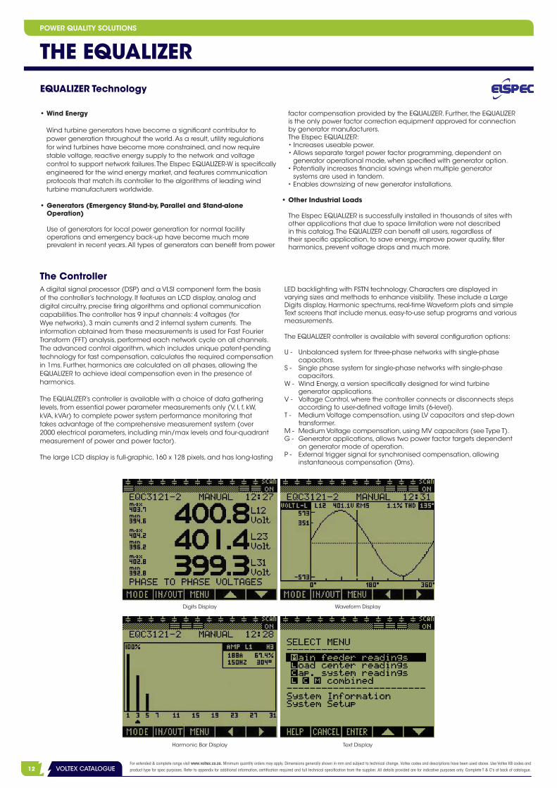
Digits Display Waveform Display
Harmonic Bar Display Text Display
The Controller
THE EQUALIZERPOWER QUALITY SOLUTIONS
A digital signal processor (DSP) and a VLSI component form the basis of the controller’s technology. It features an LCD display, analog and digital circuitry, precise firing algorithms and optional communication capabilities. The controller has 9 input channels: 4 voltages (for Wye networks), 3 main currents and 2 internal system currents. The information obtained from these measurements is used for Fast Fourier Transform (FFT) analysis, performed each network cycle on all channels. The advanced control algorithm, which includes unique patent-pending technology for fast compensation, calculates the required compensation in 1ms. Further, harmonics are calculated on all phases, allowing the EQUALIZER to achieve ideal compensation even in the presence of harmonics.
The EQUALIZER’s controller is available with a choice of data gathering levels, from essential power parameter measurements only (V, I, f, kW, kVA, kVAr) to complete power system performance monitoring that takes advantage of the comprehensive measurement system (over 2000 electrical parameters, including min/max levels and four-quadrant measurement of power and power factor).
The large LCD display is full-graphic, 160 x 128 pixels, and has long-lasting
LED backlighting with FSTN technology. Characters are displayed in varying sizes and methods to enhance visibility. These include a LargeDigits display, Harmonic spectrums, real-time Waveform plots and simple Text screens that include menus, easy-to-use setup programs and various measurements.
The EQUALIZER controller is available with several configuration options:
U - Unbalanced system for three-phase networks with single-phase capacitors.
S - Single phase system for single-phase networks with single-phase capacitors.
W - Wind Energy, a version specifically designed for wind turbine generator applications.
V - Voltage Control, where the controller connects or disconnects steps according to user-defined voltage limits (6-level).
T - Medium Voltage compensation, using LV capacitors and step-down transformer.
M - Medium Voltage compensation, using MV capacitors (see Type T).G - Generator applications, allows two power factor targets dependent
on generator mode of operation.P - External trigger signal for synchronised compensation, allowing
instantaneous compensation (0ms).

3VOLTEX CATALOGUEFor extended & complete range visit www.voltex.co.za. Minimum quantity orders may apply. Dimensions generally shown in mm and subject to technical change. Voltex codes and descriptions have been used above. Use Voltex K8 codes and product type for spec purposes. Refer to appendix for additional information, certification required and full technical specification from the supplier. All details provided are for indicative purposes only. Complete T & C's at back of catalogue. 13VOLTEX CATALOGUE
POWER QUALITY SOLUTIONS
PowerIQ - Measurement & Analysis Software
System Structure
This optional proprietary software works in parallel with the on-board controller, displaying system status and measurement results in a Windows operating environment, and allows the user remote-access to control various parameters of EQUALIZER system.All network parameters, including harmonics, can be recorded continually or for pre-selected intervals. Recording time is limited only
by the size of the computer's hard disk or other storage device (server, memory card, etc). Electrical events can be captured by associating trigger values to various network power parameters, such as low voltage or high current. The event recording will capture a user-selected before and after window of time. PowerIQ has intranet and internet support capabilities.
Switching Module
The switching module is comprised of solid-state switching elements thatprovide reliable, high-speed, transient-free operation. Single, double or three-phase electronic switches, SCR/SCR or SCR/diode, are used for each capacitor group. Switching modules are specifically selected for each EQUALIZER system based on the number of overall capacitor groups, current requirements and voltage ratings.
Cabinet Design
Each EQUALIZER system IP20/NEMA1 cabinet is made of steel sheet, which is epoxy powder coated gray (RAL 7032).
Cabinet Options
• Protection class upgrades (IP/NEMA).• Top-mounted fan unit and filters.• Lockable controller panel.• Blown fuse indication.• Magnetic door lock.• Top cable supports.• Lifting eye bolts.• Pad-lock entry.
Capacitor/Reactor Modules
Iron Core ReactorsEach Elspec EQUALIZER includes specially designed, iron core reactorsused in series with the capacitors. Each reactor is manufactured undertight control tolerances to ensure quality, constructed with a laminated,low-hysterisis loss iron core, copper windings, precision-controlled airgaps and Class H insulation (1800ºC).
Available reactor types:Inrush-only: Reactors designed to limit the inrush current which maydevelop in the capacitors during power up, avoiding damage to switching elements, fuses and capacitors.De-tuned: Prevent resonance conditions by shifting the capacitor/
network resonant frequency to below the first dominant harmonic (usually the 5th).Tuned: Designed to absorb a majority of the dominant harmonic(s), usually the 5th and/or 7th.
CapacitorsElspec EQUALIZER features MKP-type capacitors that are low-loss(0.25W/kVAr) and housed in cylindrical aluminum casings. The MKP-type capacitor is a metallised polypropylene film capacitor featuring self-healing properties and an overpressure tear-off fuse. To reduce the effects of electrical and thermal overload and extend operating life expectancy, the capacitors are connected during zero-current crossing and operated in a time-sharing mode (SCAN).
1 Group Switching Module System Structure
PowerIQ Windows Examples
THE EQUALIZER
2 VOLTEX CATALOGUEFor extended & complete range visit www.voltex.co.za. Minimum quantity orders may apply. Dimensions generally shown in mm and subject to technical change. Voltex codes and descriptions have been used above. Use Voltex K8 codes and product type for spec purposes. Refer to appendix for additional information, certification required and full technical specification from the supplier. All details provided are for indicative purposes only. Complete T & C's at back of catalogue.14 VOLTEX CATALOGUE
System Structure
THE EQUALIZER
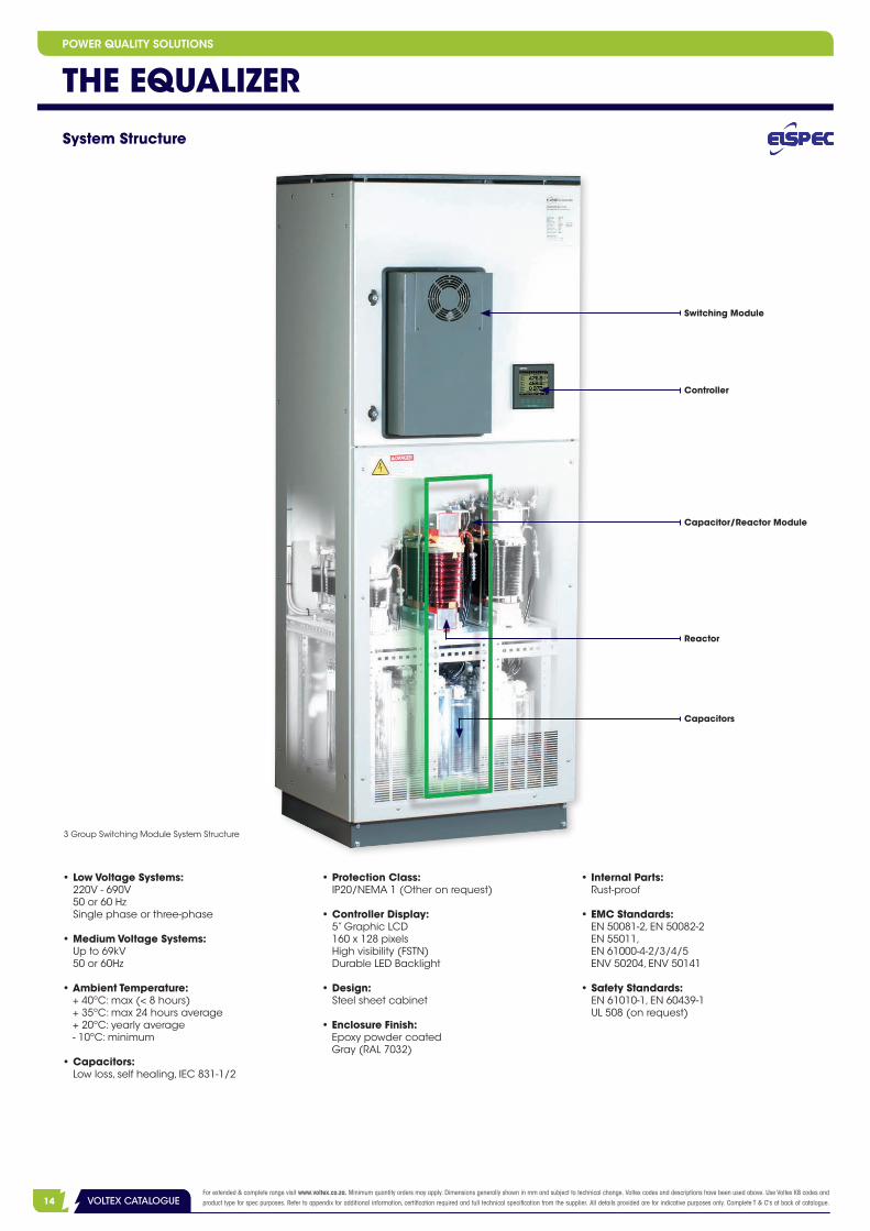
3 Group Switching Module System Structure
Switching Module
Capacitor/Reactor Module
Reactor
Controller
Capacitors
POWER QUALITY SOLUTIONS
• Low Voltage Systems: 220V - 690V 50 or 60 Hz Single phase or three-phase
• Medium Voltage Systems: Up to 69kV 50 or 60Hz
• Ambient Temperature: + 40ºC: max (< 8 hours) + 35ºC: max 24 hours average + 20ºC: yearly average - 10ºC: minimum
• Capacitors: Low loss, self healing, IEC 831-1/2
• Protection Class: IP20/NEMA 1 (Other on request)
• Controller Display: 5” Graphic LCD 160 x 128 pixels High visibility (FSTN) Durable LED Backlight
• Design: Steel sheet cabinet
• Enclosure Finish: Epoxy powder coated Gray (RAL 7032)
• Internal Parts: Rust-proof
• EMC Standards: EN 50081-2, EN 50082-2 EN 55011, EN 61000-4-2/3/4/5 ENV 50204, ENV 50141
• Safety Standards: EN 61010-1, EN 60439-1 UL 508 (on request)
3VOLTEX CATALOGUEFor extended & complete range visit www.voltex.co.za. Minimum quantity orders may apply. Dimensions generally shown in mm and subject to technical change. Voltex codes and descriptions have been used above. Use Voltex K8 codes and product type for spec purposes. Refer to appendix for additional information, certification required and full technical specification from the supplier. All details provided are for indicative purposes only. Complete T & C's at back of catalogue. 15VOLTEX CATALOGUE
POWER QUALITY SOLUTIONS
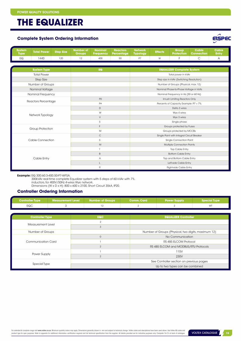
Complete System Ordering Information
System Type Total Power Step Size Number of
GroupsNominal
FrequencyReactors
PercentageNetworkTypology Effects Group
ProtectionCable
ConnectionCableEntry
EQ 1440 120 12 400 50 P7 W F C A
System Type EQ EQUALIZER Complete System
Total Power Total power in kVAr
Step Size Step size in kVAr (Switching Resolution)
Number of Groups Number of Groups (Physical, max. 12)
Nominal Voltage Nominal Phase-to-Phase Voltage in Volts
Nominal Frequency Nominal Frequency in Hz (50 or 60 Hz)
Reactors PercentageP0 Inrush Limiting Reactors Only
P# Percents of Capacity. Example: P7 = 7%.
Network Typology
D Delta 3 wires
W Wye 4 wires
V Wye 3 wires
S Single phase
Group ProtectionF Groups protected by Fuses
M Groups protected by MCCBs
Cable Connection
C Single Point with Integral Circuit Breaker
S Single Connection Point
M Multiple Connection Points
Cable Entry
T Top Cable Entry
B Bottom Cable Entry
A Top and Bottom Cable Entry
L Left-side Cable Entry
R Right-side Cable Entry
Controller Type EQC EQUALIZER Controller
Measurement Level2
3
Number of Groups Number of Groups (Physical, two digits, maximum 12)
Communication Card
0 No Communication
1 RS 485 ELCOM Protocol
2 RS 485 ELCOM and MODBUS/RTU Protocols
Power Supply1 115V
2 230V
Special TypeSee Controller section on previous pages
Up to two types can be combined
Example: EQ 300:60:3-400.50-P7-WFSA. 300kVAr real-time complete Equalizer system with 5 steps of 60 kVAr with 7%. inductors, for 400V/50Hz 4-wires Wye network. Dimensions (W x D x H): 800 x 600 x 2100, Short Circuit 35kA, IP20.
Controller Ordering Information
Controller Type Measurement Level Number of Groups Comm. Card Power Supply Special Type
EQC 3 12 2 2 WT
THE EQUALIZER

2 VOLTEX CATALOGUEFor extended & complete range visit www.voltex.co.za. Minimum quantity orders may apply. Dimensions generally shown in mm and subject to technical change. Voltex codes and descriptions have been used above. Use Voltex K8 codes and product type for spec purposes. Refer to appendix for additional information, certification required and full technical specification from the supplier. All details provided are for indicative purposes only. Complete T & C's at back of catalogue.16 VOLTEX CATALOGUE
Measured Parameters
Parameter PhasesMeasurement Level
Common 3
Frequency Common Mains • •
Phase Current L1, L2, L3 Mains, Load, Cap. • •
Neutral Current Neutral Mains • •
Phase to Phase Current* L1-2, L2-3, L3-1 Mains, Load • •
Phase Voltage L1, L2, L3 Mains • •
Neutral Voltage Neutral Mains • •
Phase to Phase Voltage L1-2, L2-3, L3-1 Mains • •
Active Power (kW) L1, L2, L3, Total Mains • •
Reactive Power (kVAr) L1, L2, L3, Total Mains, Load, Cap. • •
Apparent Power (kVA) L1, L2, L3, Total Mains, Load, Cap. • •
Power Factor L1, L2, L3, Total Mains, Load, Cap. • •
Time of use (TOU) - in, out, net, total: Active Energy (kWh) Total Mains • •
Reactive Energy (kVARh) Total Mains • •
THD at Phase Current L1, L2, L3 Mains, Load, Cap. • •
THD at Neutral Current Neutral Mains • •
THD at Phase to Phase Current L1-2, L2-3, L3-1 Mains, Load • •
THD at Phase Voltage L1, L2, L3 Mains • •
THD at Neutral Voltage Neutral Mains • •
THD at Phase to Phase Voltage L1-2, L2-3, L3-1 Mains • •
Harmonics of Phase Current L1, L2, L3 Mains, Load, Cap. •
Harmonics of Neutral Current Neutral Mains •
Harmonics of Phase to Phase Current L1-2, L2-3, L3-1 Mains, Load •
Harmonics of Phase Voltage L1, L2, L3 Mains •
Harmonics of Neutral Voltage Neutral Mains •
Harmonics of Phase to Phase Voltage L1-2, L2-3, L3-1 Mains •
Waveforms of Phase Current L1, L2, L3 Mains, Load, Cap. •
Waveforms of Neutral Current Neutral Mains •
Waveforms of Phase to Phase Current L1-2, L2-3, L3-1 Mains •
Waveforms of Phase Voltage L1, L2, L3 Mains •
Waveforms of Neutral Voltage Neutral Mains •
Waveforms of Phase to Phase Voltage L1-2, L2-3, L3-1 Mains •
System Log • •
Event Log • •
* Unique feature: metering internal current of feeder transformer (delta secondary).
THE EQUALIZERPOWER QUALITY SOLUTIONS

3VOLTEX CATALOGUEFor extended & complete range visit www.voltex.co.za. Minimum quantity orders may apply. Dimensions generally shown in mm and subject to technical change. Voltex codes and descriptions have been used above. Use Voltex K8 codes and product type for spec purposes. Refer to appendix for additional information, certification required and full technical specification from the supplier. All details provided are for indicative purposes only. Complete T & C's at back of catalogue. 17VOLTEX CATALOGUE
POWER QUALITY SOLUTIONS
EQUALIZER-ST System OverviewThe EQUALIZER-ST is a real-time, dynamic reactive power compensation system that utilises a proven industrial technology to provide an additional solution for the challenges related to large motor startups. The system itself operates at low voltage and by utilising a step-up transformer, the EQUALIZER-ST is also able to compensate for medium voltage.
Electrical Diagram - Low Voltage
TLV
M1 MN
LV Low Voltage
T Transformer
M Motor
EQ-ST EQUALIZER-ST
EQ-ST
THE EQUALIZER-ST
• Power Factor Correction• Electronics Switching >20 Milliseconds • Full Compensation• Designed Motor Start Optimisation
Features and Benefits

2 VOLTEX CATALOGUEFor extended & complete range visit www.voltex.co.za. Minimum quantity orders may apply. Dimensions generally shown in mm and subject to technical change. Voltex codes and descriptions have been used above. Use Voltex K8 codes and product type for spec purposes. Refer to appendix for additional information, certification required and full technical specification from the supplier. All details provided are for indicative purposes only. Complete T & C's at back of catalogue.18 VOLTEX CATALOGUE
A motor start demands very high reactive power for a relatively short period of time.
The starting current of an AC motor usually varies from 6 to 8 times the nominal current. This is due to the large amount of energy that is required to magnetise the motor, enough to overcome the inertia the system has at standstill. The high current drawn from the network usually causes problems such as voltage drop, high transients and in some cases, uncontrolled shutdowns. The graph below demonstrates a typical startup phenomena for a 500kW motor with a power factor of 0.89:
The Electrical Challenge
Electrical Diagram - Medium Voltage
TMV
M1 MN
SUT690V
LVLV Low Voltage
T Transformer
M Motor
MV Medium Voltage
SUT Step-up Transformer
EQ-ST EQUALIZER-ST
EQ-ST
• On Startup: The demand on the nominal current is 6 times more, with a power factor of 0.3;• On Steady State: P = 500 kW, S = 562 kVA, Q = 256 kVAr;• During Startup: S = 562 x 6 = 3,372 kVA, P = 1,012 kW, Q = 3,217 kVAr;• Startup Duration: t1 - t2 = 10 sec;
P Active Power
Q Reactive Power
Steady State
Startup
t TimeP
Q
t1t2
Centralised Motor Startup Compensation
The EQUALIZER-ST is a centralised motor startup solution, that provides fast compensation in real-time. In an environment of many motors, one EQUALIZER-ST system serves any number of motors, assuming that two motors are not started simultaneously. By eliminating the need to use individual motor soft starters for each motor, makes the system much more cost effective in comparison to other compensation systems.
THE EQUALIZER-STPOWER QUALITY SOLUTIONS
3VOLTEX CATALOGUEFor extended & complete range visit www.voltex.co.za. Minimum quantity orders may apply. Dimensions generally shown in mm and subject to technical change. Voltex codes and descriptions have been used above. Use Voltex K8 codes and product type for spec purposes. Refer to appendix for additional information, certification required and full technical specification from the supplier. All details provided are for indicative purposes only. Complete T & C's at back of catalogue. 19VOLTEX CATALOGUE
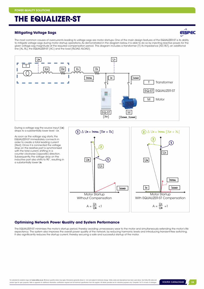
Mitigating Voltage Sags
The most common causes of overcurrents leading to voltage sags are motor startups. One of the main design features of the EQUALIZER-ST is its ability to mitigate voltage sags during motor startup operations. As demonstrated in the diagram below, it is able to do so by injecting reactive power, for the given voltage sag magnitude at the required compensation period. This diagram includes a transformer [T] its impedance [XLT, RLT], an additional line [XL, RL], the EQUALIZER-ST [XC] and the load [RLOAD, XLOAD].
EQ-ST EQUALIZER-ST
T Transformer
M Motor
U0
XLT RLT XL RL
U1
ITOTAL IC
[XC]M
ILOAD
[RLOAD, XLOAD]
T
EQ-ST
During a voltage sag the source input [U0] drops to a substantially lower level - U1.
As soon as the voltage sag starts, the EQUALIZER-ST immediately connects in order to create a total leading current [Red]. Once it is connected the voltage drop on the resistive part is synchronised with the total current, shifting in a counter clockwise [opposite] direction. Subsequently, the voltage drop on the inductive part also shifts to 90˚, resulting in a substantially lower U0.
∆ UX = ITOTAL [XLT + XL] 2
A = =1 U1
U0
Motor Startup With EQUALIZER-ST Compensation
12
U0
U1
ILOADIC
ITOTAL
∆ UR = ITOTAL [RLT + RL] 1
1
2
U0
U1
ILOAD
Motor Startup Without Compensation
A = <1 U1
U0
Optimising Network Power Quality and System Performance
The EQUALIZER-ST minimises the motor’s startup period, thereby avoiding unnecessary wear to the motor and simultaneously extending the motor’s life expectancy. The system also improves the overall power quality of the network, by reducing harmonic levels and introducing transient-free switching. It also significantly reduces the startup current, thereby securing a safe and successful startup of the motor.
THE EQUALIZER-STPOWER QUALITY SOLUTIONS
2 VOLTEX CATALOGUEFor extended & complete range visit www.voltex.co.za. Minimum quantity orders may apply. Dimensions generally shown in mm and subject to technical change. Voltex codes and descriptions have been used above. Use Voltex K8 codes and product type for spec purposes. Refer to appendix for additional information, certification required and full technical specification from the supplier. All details provided are for indicative purposes only. Complete T & C's at back of catalogue.20 VOLTEX CATALOGUE
Motor Current Waveform
EQUALIZER-ST Current Waveform
Network Current Waveform
300V
-300V
0V
2kA
-2kA
0kA
2kA
-2kA
0kA
2kA
-2kA
0kA
Motor Current RMS
Network Voltage RMS
EQUALIZER-ST Current RMS
Network Current RMS
Network Current Waveform
23 V
190V
210V
2kA
0kA
1kA
2kA
0kA
1kA
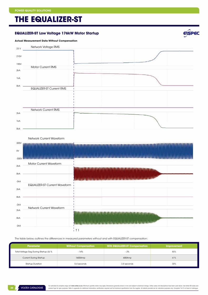
EQUALIZER-ST Low Voltage 176kW Motor Startup
The table below, outlines the differences in measured parameters without and with EQUALIZER-ST compensation:
T 1
Actual Measurement Data Without Compensation
Parameter Without Compensation With EQUALIZER-ST Compensation Improvement
Total Voltage Sag During Startup ∆U % - 14% - 2% 85%
Current During Startup 1600Amp 600Amp 61%
Startup Duration 5.4 seconds 3.8 seconds 30%
THE EQUALIZER-STPOWER QUALITY SOLUTIONS

3VOLTEX CATALOGUEFor extended & complete range visit www.voltex.co.za. Minimum quantity orders may apply. Dimensions generally shown in mm and subject to technical change. Voltex codes and descriptions have been used above. Use Voltex K8 codes and product type for spec purposes. Refer to appendix for additional information, certification required and full technical specification from the supplier. All details provided are for indicative purposes only. Complete T & C's at back of catalogue. 21VOLTEX CATALOGUE
EQUALIZER-ST Low Voltage 176kW Motor Startup
Actual Measurement Data With EQUALIZER-ST Compensation
Motor Current Waveform
EQUALIZER-ST Current Waveform
Network Current Waveform
300V
-300V
0V
2kA
-2kA
0kA
2kA
-2kA
0kA
2kA
-2kA
0kA
Motor Current RMS
EQUALIZER-ST Current RMS
Network Current RMS
230V
190V
210V
2kA
0kA
1kA
2kA
0kA
1kA
2kA
0kA
1kA
T 1
Network Current Waveform
Network Voltage RMS
THE EQUALIZER-STPOWER QUALITY SOLUTIONS

2 VOLTEX CATALOGUEFor extended & complete range visit www.voltex.co.za. Minimum quantity orders may apply. Dimensions generally shown in mm and subject to technical change. Voltex codes and descriptions have been used above. Use Voltex K8 codes and product type for spec purposes. Refer to appendix for additional information, certification required and full technical specification from the supplier. All details provided are for indicative purposes only. Complete T & C's at back of catalogue.22 VOLTEX CATALOGUE
EQUALIZER-ST Low Voltage 176kW Motor Startup
Zoom-In EQUALIZER-ST Step-By-Step Compensation
Motor Current Waveform
Network Current Waveform
StartupInitiation
Startup Termination
EQUALIZER-ST Current Waveform-2kA
0kA
2kA
-2kA
0kA
2kA
-2kA
0kA
2kA
EQUALIZER-ST Medium Voltage - 1.5Mw Motor Startup Actual Measurement Data Without Compensation
Medium Voltage Startup
Motor Current RMS
Network Voltage RMS
EQUALIZER-ST Current RMS
11kV
10.5kV
600A
0 A
-600A
600A
300A
0A
THE EQUALIZER-STPOWER QUALITY SOLUTIONS

3VOLTEX CATALOGUEFor extended & complete range visit www.voltex.co.za. Minimum quantity orders may apply. Dimensions generally shown in mm and subject to technical change. Voltex codes and descriptions have been used above. Use Voltex K8 codes and product type for spec purposes. Refer to appendix for additional information, certification required and full technical specification from the supplier. All details provided are for indicative purposes only. Complete T & C's at back of catalogue. 23VOLTEX CATALOGUE
THE EQUALIZER-ST66kV and 11kV Network Startups
The table below, outlines the differences in measured parameters without and with EQUALIZER-ST compensation:
66kV
66kV Network Voltage
11kV Current RMS
11kV
10.5kV
600A
11kV Network Voltage
300A
64.4kV
62.8kV
T 10A
Parameter Without Compensation With EQUALIZER-ST Compensation Improvement
Total Voltage Sag During Startup At 66 kV ΔU % - 4.1% - 1.4% 65%
Total Voltage Sag During Startup At 11 kV ∆U % - 8.8% - 2.8% 68%
Total Current At 11 kV 580 Amp 280 Amp 51%
Actual Measurement Data With EQUALIZER-ST Compensation
Motor Current RMS
EQUALIZER-ST Current RMS
Medium Voltage Startup
11kV
10.5kV
600A
0A
-600A
600A
300A
0A
Network Voltage RMS
POWER QUALITY SOLUTIONS

2 VOLTEX CATALOGUEFor extended & complete range visit www.voltex.co.za. Minimum quantity orders may apply. Dimensions generally shown in mm and subject to technical change. Voltex codes and descriptions have been used above. Use Voltex K8 codes and product type for spec purposes. Refer to appendix for additional information, certification required and full technical specification from the supplier. All details provided are for indicative purposes only. Complete T & C's at back of catalogue.24 VOLTEX CATALOGUE
THE EQUALIZER-ST66kV and 11kV Network Startups
66 kV
Controller 1
~~
EQUALIZER-ST 8.4 MVAr
Motor 3 1.5 MW
Motor 4 1.5 MW
Motor 11.5 MW
Motor 2 1.5 MW
Sub-StationT1 - Feeder Transformer
220kV / 66kV100 MVA Zsc = 20%
T2 - Feeder Transformer220kV/66kV100 MVA Zsc = 20%
15 km
T3 - Feeder Transformer66kV/11kV33 MVA Zsc = 10%
T4 - Step-up Transformer11kV/0.69kV6 MVA Zc = 8.5%
Controller 2
11kV
Mains
Actual Electrical Diagram - 66kV and 11kV Network
66kV Network Voltage
11kV Current RMS
11kV Network Voltage
66kV
11kV
10.5kV
600A
300A
0A
64.4kV
62.8kV
T 1
POWER QUALITY SOLUTIONS

3VOLTEX CATALOGUEFor extended & complete range visit www.voltex.co.za. Minimum quantity orders may apply. Dimensions generally shown in mm and subject to technical change. Voltex codes and descriptions have been used above. Use Voltex K8 codes and product type for spec purposes. Refer to appendix for additional information, certification required and full technical specification from the supplier. All details provided are for indicative purposes only. Complete T & C's at back of catalogue. 25VOLTEX CATALOGUE
THE EQUALIZER-ST
Specifications
Low Voltage System which is designed to control the reactive energy at MV using a boosting
transformer*
Primary: Up to 66kV
Secondary: 690V (typically)
Start-up Time Up to 30 seconds
Duty Cycle 5%
Ambient Temperature Limits -10 ºC up to 40 ºC
Capacitors Low loss, self healing IEC 831-1/2
Protection Class IP 20/NEMA 1 (Others on Request)
Design Sheet Steel Cabinet
Enclosure Finish Epoxy powder coated gray (RAL 7032)
Internal Parts Rust-proof alu-zinc
EMC Standards
EN 50081-2 EN 61000-4-2/3/4/5
EN 50082-2 ENV 50204
EN 55011 ENV 50141
Safety StandardsEN 61010-1
EN 60439
Cabinets Low Voltage 400V Medium Voltage 690V
210cm
100cm 80cm
Reactive Power [kVAr] Up to 850kVAr Per Cabinet Up to 1400kVAr Per Cabinet
Dimensions [H x W x D] 210 x 100 x 80cm 210 x 100 x 80cm
Number of cabinets (steps) per system: Up to 12
* The System can be used without a boosting transformer for networks up to 690V (480V, 400V, etc.)
POWER QUALITY SOLUTIONS

Voltex MV/LV Solutions
• Fully Type Tested Panels• Production of LV/MV Panels and Switchboards• Variable Speed Drives• Motor Control Centers • Distribution Boards • Mini-Subs • Standby Generators • Specialised Assemblies • Custom Design by Application • Cost Effective Manufacturing • Flexible Delivery Schedule
Design and manufacturing of LV and MV Switchboards and Motor Control Panels
Fields of Expertise:
www.voltex.co.za [email protected]
MV/LV Solutions

POWER QUALITY METERING AND MONITORING
PQSCADA POWER QUALITY MANAGEMENT SUITE
Simplifies TroubleshootingConfigure, Control, Monitor, Compare and Analyse Time Synchronisation data
G4K FIXED POWER QUALITY ANALYSER BLACKBOX
Continuous Waveform RecordingsSuperior Accuracy
Threshold - Free Setup
No Missed EventsQuick and Easy SetupRemote Connectivity
G4500/G3500 PORTABLE POWER QUALITY ANALYSER BLACKBOX
DIGITAL FAULT RECORDER (DFR) BLACKBOX
Continuous Waveform RecordingsAdvanced Fault Location1 µsecond Time Synchronisation

2 VOLTEX CATALOGUEFor extended & complete range visit www.voltex.co.za. Minimum quantity orders may apply. Dimensions generally shown in mm and subject to technical change. Voltex codes and descriptions have been used above. Use Voltex K8 codes and product type for spec purposes. Refer to appendix for additional information, certification required and full technical specification from the supplier. All details provided are for indicative purposes only. Complete T & C's at back of catalogue.28 VOLTEX CATALOGUE
POWER QUALITY METERING AND MONITORING
Tailored for PQ Analysis at any location, the portable G4500 and G3500 BLACKBOX device series has been especially designed to address the needs of:• Site Engineers• Electrical Consultants• Utilities
Note:1 Only 5 Voltage Leads Supplied with G3500 2 G4500 Unit Only
• No Missed Events • Quick & Simple Setup• Remote Connectivity• Absolutely identify all power quality events• Plug it in and never miss another event
G4500/G3500 Portable Power Quality in High Definition
The Perfect Portable Solution
All Inclusive• Everything you need in a Portable Power Quality Solution and more:• Four Flexible AC Current Clamps (Automatically Detected)• Seven Voltage Leads1 (Automatically Detected)• Durable Carrying Case• Rechargeable Power Supply (2 Hours Standby)• Wireless Network2
• PQSCADA/Investigator Software CD• Mobile Analysis Lab
G4500/G3500 PORTABLE POWER QUALITY ANALYSER BLACKBOX

3VOLTEX CATALOGUEFor extended & complete range visit www.voltex.co.za. Minimum quantity orders may apply. Dimensions generally shown in mm and subject to technical change. Voltex codes and descriptions have been used above. Use Voltex K8 codes and product type for spec purposes. Refer to appendix for additional information, certification required and full technical specification from the supplier. All details provided are for indicative purposes only. Complete T & C's at back of catalogue. 29VOLTEX CATALOGUE
• No Missed Events The BLACKBOX Portable, coined POWER QUALITY IN HIGH DEFINITION, records all the parameters, all the time. Capture everything for more than a year1,2: trends, Volts/Amps/Hz, events, harmonics, THD, flicker, power and energy to get down to the root cause of all Power Quality issues. It is the only measurement device capable of FFT (Fast Fourier Transform) computation, for every cycle, simultaneously recording both IEC 61000-4-30 and Cycle-By-Cycle measurements.
• Quick and Simple Setup Specifically designed for a quick and easy portable setup, simply connect the Portable BLACKBOX, record and measure all electrical information. The device doesn’t rely on any pre-programmed triggers, events or thresholds. If so required, the device may also include individual pre-programmed parameters.
• Remote Connectivity Built-in web server allows remote monitoring using standard web browsers. With a 802.11 access point and Ethernet router b/g1, the BLACKBOX Portable enables remote analysis: Intuitive: Graphical Web Screens, that are easy to operate. Accessible: Internet access from any location via a variety of communication gateways. Manageable: Monitor and analyse all your network data. Control: System administration made easy via three user-levels.
• Plug-and-Play The Portable BLACKBOX is equipped with a plug-and-play probe interface that allows it to automatically detect probes and clamps during setup.
Features and Benefits
Full Compliance with IEC 61000-4-30 Class A
Far surpassing the highest standards set by the industry, the Portable BLACKBOX complies with standards for: aggregations, time clock uncertainty, flagging, and transient influence quantities.
Note:1 G4500 Unit Only. 2 Depending on the Selected Resolution and on the Individual Network Condition.
StatisticsTrends Phasors
Maps
Event Focus
Harmonics
By effectively processing enormous amounts of recorded network data, PQSCADA Software provides an immediate, and understandable picture of everything that happened within the network, anywhere, anytime.
Advanced PQSCADA
G4500/G3500 PORTABLE POWER QUALITY ANALYSER BLACKBOX
Automated Reports
Generate automated reports set to any customised pre-scheduled period. Event data is exportable to either COMTRADE or PQDIF, and all other data to PDF, EXCEL and HTML.
POWER QUALITY METERING AND MONITORING

2 VOLTEX CATALOGUEFor extended & complete range visit www.voltex.co.za. Minimum quantity orders may apply. Dimensions generally shown in mm and subject to technical change. Voltex codes and descriptions have been used above. Use Voltex K8 codes and product type for spec purposes. Refer to appendix for additional information, certification required and full technical specification from the supplier. All details provided are for indicative purposes only. Complete T & C's at back of catalogue.30 VOLTEX CATALOGUE
Type Description Product Code
GPS (Global Positioning System)
The GPS provides an optimal mobile time synchronisation solution for accurate time data via satellite signal. In the absence of many other technologies, it synchronises time at any remote site location.
O10860
Multi-Frequency 3.5G Wireless Modem
The Wireless GPRS Modem provides fast mobile communication access and offers the perfect solution in industrial data communication. It is fitted with a SIM Card drawer structure, and it may be connected with any standard RS-422 interface. Data is transmitted at 3.5G and the modem is fully compatible with GSM/GPRS/EDGE.
O10861
DC Current Clamp
Model SOA-0270-1400
O10862
Current Measurement 1,500A DC / 1,000A AC
Output Signal 1m V/A, 10m V/A
Operating Temperature - 20°C to + 60°C
Cable Length 1.4m
1-6 A Mini Clamp
Model SOA-0010-0500
O10863
Current Measurement Up to 6A AC (1A Nominal)
Output Signal 100 mV/A
Operating Temperature - 20°C to + 60°C
Cable Length 1.2m
Optional Accessories
G4500/G3500 PORTABLE POWER QUALITY ANALYSER BLACKBOX
POWER QUALITY METERING AND MONITORING

3VOLTEX CATALOGUEFor extended & complete range visit www.voltex.co.za. Minimum quantity orders may apply. Dimensions generally shown in mm and subject to technical change. Voltex codes and descriptions have been used above. Use Voltex K8 codes and product type for spec purposes. Refer to appendix for additional information, certification required and full technical specification from the supplier. All details provided are for indicative purposes only. Complete T & C's at back of catalogue. 31VOLTEX CATALOGUE
Type Description Product Code
100A Mini Clamp
Model SOA-0180-5000
O10864
Measurement Range Up to 100APK AC
“Hole” Dimensions 10mm Max
Operating Temperature - 20°C to + 60°C
Cable Length 1.2m
Custom Clamp 3-Flexible Current Probes
Model SOA-3003-0270
O10865
Current Range 30A/300A/3000A AC RMS
Operating Temperature - 20°C to + 65°C
Probe Cable Length 610mm (24”)
Probe Cable Diameter 194mm (7.5”)
Custom Clamp 1-Flexible Current Probes
Model SOA-3003-0270
O10866
Current Range 30A/300A/3000A AC RMS
Operating Temperature - 20°C to + 65°C
Probe Cable Length 610mm (24”)
Probe Cable Diameter 194mm (7.5”)
Optional Accessories
Note:• Elspec’s unique calibration procedure calculates both clamp and device inaccuracy, thereby eliminating clamp uncertainty and yielding a superior
power measurement accuracy.• IEC 61000-4-30 Class A Test Reports• Upon request, Elspec can provide a comprehensive functionality and calibration test report for each analyser. Fully automated calibration software is
also available for customers in-house use.
POWER QUALITY METERING AND MONITORING
G4500/G3500 PORTABLE POWER QUALITY ANALYSER BLACKBOX

2 VOLTEX CATALOGUEFor extended & complete range visit www.voltex.co.za. Minimum quantity orders may apply. Dimensions generally shown in mm and subject to technical change. Voltex codes and descriptions have been used above. Use Voltex K8 codes and product type for spec purposes. Refer to appendix for additional information, certification required and full technical specification from the supplier. All details provided are for indicative purposes only. Complete T & C's at back of catalogue.32 VOLTEX CATALOGUE
Product Series G3500 G4500
Product Specifications
Voltage Sampling Rate, Maximum Samples/Cycle 512 1024
Voltage Harmonics (Individual, Even, Odd, Total) Up to 255 TH 511 TH
Type of Analog to Digital Converter 16/201 bit 16/201 bit
Storage Capacity
Internal Memory 256 MB/256GB2 32 GB/32TB2
Power Quality Analysis
Transient Detection, Microseconds (50Hz/60Hz) 39/32.5µs 19.5/16.3µs
Communication Ports
Ethernet Ports 1 3
Wi-Fi Communications (802.11g) - 1
Power Over Ethernet (PoE- Out) -
Digital Input 4 4
Measurements
Voltage Channels 4 (3 Phases + Neutral) 4 (3 Phases + Neutral) + 1 DC
Current Channels 4 (3 Phases + Neutral) 4 (3 Phases + Neutral) + 1Grn/DC
Physical
Dimensions 314 x 84 x 269mm 314 x 84 x 271mm
Weight 3.7kg 3.7kg
Applicable Measurement Standards Control
EN50160, IEEE1159, IEEE519, IEC61000-4-15, IEC61000-4-7,
IEC61000-4-30 Class A
Comprehensive web server for local and remote real-time monitoring and control
Applicable EMC Standards Applicable Environmental Standards
EN61326, CFR47FCC, CISPR11 Group 1, FCC PART 15 Subpart B,
EN61010-2, IEC61000-3-3, IEC61000-4-2, IEC61000-4-3,
IEC61000-4-4, IEC61000-4-5, IEC61000-4-6, IEC61000-4-11
IEC60068-2-1, 2, 6, 27, 30, 75
Applicable Safety Standards Serial Ports
EN61010-1:2001 2nd Edition RS-232
RS-485
Voltage Current
Nominal Full Scale 1000V Current Channels Receive I1-I4: 0-10 VPk I5: 0-3 VPk From Clamp
Maximum Peak Measurement 8000V Uncertainty 0.1% ±0.1 mV
Input Impedance 3MΩ
Uncertainty 0.1% of Nominal
Power Supply Time
Operating Range 100-260 VAC: 50/60 Hz 100-300 VDC Real Time Clock ±1 Second per 24 Hours
Auxiliary DC Supply 48 Vdc Synchronisation Device Accuracy
Auxiliary Supply – PoE In According to 802.3af GPS 100-200µs
Battery Backup 2 Hours IRIG B 100-200µs
DCF-77 ±15ms
SNTP Server 50-100µs
Frequency Environmental Conditions
Fundamental Frequency 42.5 Hz to 69 Hz Operation Temperature 0°C to 50°C (32°F to 122 °F)
Frequency Resolution 10 mHz Storage Temperature -20°C to 60°C (-4°F to 140 °F)
Frequency Accuracy ±10 mHz
Product Selection Guide
Note:1 Effective bits.2 Equivalent memory size needed without compression.• Disclaimer: Specifications subject to change without prior notice.
POWER QUALITY METERING AND MONITORING
Specifications
G4500/G3500 PORTABLE POWER QUALITY ANALYSER BLACKBOX

3VOLTEX CATALOGUEFor extended & complete range visit www.voltex.co.za. Minimum quantity orders may apply. Dimensions generally shown in mm and subject to technical change. Voltex codes and descriptions have been used above. Use Voltex K8 codes and product type for spec purposes. Refer to appendix for additional information, certification required and full technical specification from the supplier. All details provided are for indicative purposes only. Complete T & C's at back of catalogue. 33VOLTEX CATALOGUE
PQSCADA POWER QUALITY MANAGEMENT SUITE
Elspec’s innovative PQSCADA Power Quality Management Suite software simplifies troubleshooting. With this user-friendly system, you can now configure, control, monitor, compare, and analyse time synchronised data from any number of BLACKBOX devices, within a particular site or across many sites.
PQSCADA Power Quality Management Suite (Enterprise Edition)
Features and Benefits• Data Analysis
Powerful analysis software that allows you to focus on detailed data over a wide range of parameters. With a simple click of your mouse, you can zoom in from a year’s worth of data to less than a millisecond in order to identify power quality details that include trends, Volts, Amps, Hz, events, harmonics, THD, flicker, power and energy.
POWER QUALITY METERING AND MONITORING

2 VOLTEX CATALOGUEFor extended & complete range visit www.voltex.co.za. Minimum quantity orders may apply. Dimensions generally shown in mm and subject to technical change. Voltex codes and descriptions have been used above. Use Voltex K8 codes and product type for spec purposes. Refer to appendix for additional information, certification required and full technical specification from the supplier. All details provided are for indicative purposes only. Complete T & C's at back of catalogue.34 VOLTEX CATALOGUE
PQSCADA POWER QUALITY MANAGEMENT SUITE
PQSCADA/Investigator Versatility
• Automated Report Generator PQSCADA has been uniquely adapted to generate automatic reports, based on any specification, on an unique electrical event or simply according to a set time schedule (monthly, daily, weekly). Conforming to the highest industry standards, the templates of the Automated Report Function are not only based on EN50160 standards, but also on a wide range of standards from other major countries. These templates may also be uniquely adapted to suit the requirements of individual users.
• Export Compatibility All automated reports can be easily exported to many compatible formats such as: COMTRADE and PQDIF (event reports), PDF, EXCEL, HTML and TXT (all other reports).
• Automatic Notifications Easily set requirements or parameters for automatic notification on any electrical event. These notifications can be sent by a variety of communication means: E-Mail, SMS and/or Pop-Ups.
• Multiple Device Synchronisation Each individual BLACKBOX continuously records waveforms that PQSCADA will automatically collect, store and process. Analysis of any event propagation requires measurements taken from multiple locations. The accuracy level is dependent on precise time synchronisation, and as such, each device can be continuously synchronised to an accurate external time source or to each other. Due to the continuous waveform recording from multiple points, any event can be clearly viewed as it propagates from one point to another, providing a clear and comprehensive picture of conditions leading up to, during, and after event.
The PQSCADA and associated Investigator Software Applications offer a wide range adaptation and options for configuration making it extremely versatile to meet the needs and requirements of individual users. The PQSCADA Server forms the heart of the BLACKBOX device series, and may be connected to an infinite number of devices.
Download
PQSCADA collects all waveform data that has been continuously recorded in the compressed PQZIP format.
Process
The data is processed and organised for quick access and storage. A wide range of electrical parameters are then calculated based on the raw PQZIP data. The reorganised PQZIP data, and the calculated parameters with statistics included, are stored and available on the network for later retrieval.
Visualise
Detailed data can be easily analysed by any number of clients at any location. The Investigator Software provides an immediate, comprehensive and understandable picture of everything that happened within the network.
Deliver
All the electrical information, including event flagging and notifications are delivered over a number of communication gateways. This feature includes report exports in various compatible formats such as COMTRADE, PQDIF, CSV, RTF, HTML, PDF, etc.
Real-Time StatusWith a simple click of your mouse, map all your BLACKBOX units on site, and establish the status of all your units down to a singular unit.
POWER QUALITY METERING AND MONITORING

3VOLTEX CATALOGUEFor extended & complete range visit www.voltex.co.za. Minimum quantity orders may apply. Dimensions generally shown in mm and subject to technical change. Voltex codes and descriptions have been used above. Use Voltex K8 codes and product type for spec purposes. Refer to appendix for additional information, certification required and full technical specification from the supplier. All details provided are for indicative purposes only. Complete T & C's at back of catalogue. 35VOLTEX CATALOGUE
Source Collection
Download
TCP / IP TCP / IP
Process
Manage
Deliver Visualise
3 Optional Operation ScenariosEnd-users may choose how to utilise PQSCADA and Investigator Software Applications according to their requirements. Elspec offers 3 operational scenarios:
• Conventional Profile Via the Network Within this scenario, choose how to take advantage of the PQSCADA and Investigator Software Programs. PQSCADA is installed on a server, the system is managed on the network, with the Investigator application accessible via the internet.
• Elspec’s Hosting Profile Data from all installed devices are transmitted to Elspec’s Data Storage Center. Data is accessed and analysed with the Investigator Client programs. Alternatively, a third party can be authorised to analyse the Power Quality Data via this option.
• Stand-Alone Profile Individually installed devices may record data at any location (usually remote) over a chosen period of time (up to 1 year). Data is accessed and downloaded on an ad-hoc basis at the location using one of the many available connection gateways (wireless, TCP/IP connection). Downloaded data may either be redirected and managed using the user’s own Server Profile, or to Elspec’s Host Server Profile.
Unparalleled Data Recording Capability Record and store all electrical information, all the time, for more than a year with no gaps in the data.
Advanced PQSCADA
PQSCADA POWER QUALITY MANAGEMENT SUITE
Data RetrievalA wide range of communication gateways can be used to rapidly retrieve the compressed PQZIP data at any user-defined time interval.
POWER QUALITY METERING AND MONITORING

2 VOLTEX CATALOGUEFor extended & complete range visit www.voltex.co.za. Minimum quantity orders may apply. Dimensions generally shown in mm and subject to technical change. Voltex codes and descriptions have been used above. Use Voltex K8 codes and product type for spec purposes. Refer to appendix for additional information, certification required and full technical specification from the supplier. All details provided are for indicative purposes only. Complete T & C's at back of catalogue.36 VOLTEX CATALOGUE
POWER QUALITY METERING AND MONITORING
The innovative design of the G4400 BLACKBOX device series is a technological breakthrough providing the perfect PQ Analysis solution. Its’ enhanced capabilities are uniquely adaptable to address the individual needs and requirements for almost any business and/or application.
• Continuous Waveform Recordings • Superior Accuracy• Threshold-Free Setup
G4K The Future of Power Quality
The Perfect Fixed Solution
G4K FIXED POWER QUALITY ANALYSER BLACKBOX
Electrical Utilities Industrial and Commercial
• Produce Detailed and Comprehensive Statistical Records• Avoid Customer Disputes• Troubleshoot all Power Quality Issues at a High Resolution • Ensure a Reliable and Consistent Supply of Energy • Assess the Status of your System Apparatus
• Measure & Analyse System Efficiency, Provide Solutions, Increase Profits• Empower Negotiating Capabilities with Power Providers• Detect Electric Bill Inconsistencies• Avoid PQ Compliance Issues

3VOLTEX CATALOGUEFor extended & complete range visit www.voltex.co.za. Minimum quantity orders may apply. Dimensions generally shown in mm and subject to technical change. Voltex codes and descriptions have been used above. Use Voltex K8 codes and product type for spec purposes. Refer to appendix for additional information, certification required and full technical specification from the supplier. All details provided are for indicative purposes only. Complete T & C's at back of catalogue. 37VOLTEX CATALOGUE
Full Compliance with IEC 61000-4-30 Class A
Far surpassing the highest standards set by the industry, the BLACKBOX device series complies with standards for: aggregations, time clock uncertainty, flagging, and transient influence quantities.
Unique Features
• Continuous Waveform Recordings Exclusive only to the G4K, the device is able to record and store all electrical waveforms, all the time, for more than a year (Voltage at 1024 samples per cycle, and Current at 256 samples per cycle1,2), with no gaps in the data. These innovations in the technology provide a clear and comprehensive picture of conditions leading up to, during, and after an event.
• Superior Accuracy Elspec’s pioneering measurement method utilises a dual-range gain of 2x16 Bit to yield, a superior accuracy far surpassing IEC 61000-4-30 Class A requirements, thereby capturing the finest details and deviations in PQ parameters.
• Threshold-Free Setup The G4K’s setup is free from any thresholds, triggers, and events. If required, the device may also be pre programmed with any individual parameters during setup for event flagging.
• SCADA Compatible The BLACKBOX device series is equipped with standard industrial protocols for seamless integration into any existing SCADA system.
• Standard Compliance Testing The G4K provides PQ parameters according to EN50160 and IEC 61000-4-30, including other National Standards. Parameters may also be customised to comply with any other unique standards or requirements.
• Remote Monitoring Capabilities The G4K is specifically designed to connect either via TCP/IP/RTU/GPRS Wireless for ease of use. Data may be analysed over any network, at any remote location.
Note:1 G4430 Unit Only. 2 Sampling Rate For Both Voltage & Current May Also Range At 512 Samples Per Cycle.
StatisticsTrends Phasors
Maps
Event Focus
Harmonics
Automated Reports
Generate automated reports set to any customised pre-scheduled period. Event data is exportable to either COMTRADE or PQDIF, and all other data to PDF, EXCEL and HTML.
The Power Quality Management Software Suite (Enterprise Edition) empowers the G4K with an unparalleled data recording capability providing the most accurate detection and isolation of PQ anomalies for the diagnosis and effective maintenance of equipment.
Elspec’s innovative PQSCADA Power Quality Management Suite software simplifies troubleshooting. This user-friendly system allows for the control, configuration, comparison and analysis of time-synchronised data recorded by any number of BLACKBOX devices within a particular site or across many sites.
Advanced PQSCADA
POWER QUALITY METERING AND MONITORING
G4K FIXED POWER QUALITY ANALYSER BLACKBOX

2 VOLTEX CATALOGUEFor extended & complete range visit www.voltex.co.za. Minimum quantity orders may apply. Dimensions generally shown in mm and subject to technical change. Voltex codes and descriptions have been used above. Use Voltex K8 codes and product type for spec purposes. Refer to appendix for additional information, certification required and full technical specification from the supplier. All details provided are for indicative purposes only. Complete T & C's at back of catalogue.38 VOLTEX CATALOGUE
Type Description Product Code
G4100 Display
The Elspec G4100 display unit provides full control over all the analysers, allowing technicians and field operators to fully configure and operate every single analyser in the network. The G4100 can be used as a hand held monitoring and configuration tool, connectable via a TCP/IP connection.
O10976
GPS (Global Positioning System)
The GPS provides an optimal mobile time synchronisation solution for accurate time data via satellite signal. In the absence of many other technologies, it synchronises time at any remote site location.
O10860
Multi-Frequency 3.5G Wireless Modem
The Wireless GPRS Modem provides fast mobile communication access and offers the perfect solution in industrial data communication. It is fitted with a SIM Card drawer structure, and it may be connected with any standard RS-422 interface. Data is transmitted at 3.5G, and the modem is fully compatible with GSM/GPRS/EDGE.
O10861
G4400 Multi I/O Expansion
The G4400 optional module expands the monitoring capabilities of the BLACKBOX with additional digital and analog I/O ports. The I/O Engine periodically checks the inputs and sets the outputs accordingly. Energy pulses, Digital Inputs and Analog Inputs are logged continuously, from Current to Voltage relays and stored in the PQZIP files.
O10977
Optional Accessories
Note: IEC 61000-4-30 Class A Test ReportsUpon request, Elspec can provide a comprehensive functionality and calibration test report for each analyser. Fully automated calibration software is also available for customers in-house use.
POWER QUALITY METERING AND MONITORING
G4K FIXED POWER QUALITY ANALYSER BLACKBOX

3VOLTEX CATALOGUEFor extended & complete range visit www.voltex.co.za. Minimum quantity orders may apply. Dimensions generally shown in mm and subject to technical change. Voltex codes and descriptions have been used above. Use Voltex K8 codes and product type for spec purposes. Refer to appendix for additional information, certification required and full technical specification from the supplier. All details provided are for indicative purposes only. Complete T & C's at back of catalogue. 39VOLTEX CATALOGUE
Product Selection Guide
Product Series G4410 G4420 G4430
Real-Time Measurements Voltage Sampling Rate, Maximum Samples/Cycle 256 512 1024
Voltage Harmonics (Individual, Even, Odd, Total) Up to 127th 255th 511th
Type of Analog to Digital Converter 16/201 bit 16/201 bit 16/201 bit
Storage Capacity
Internal Memory 128MB 4GB 16GB
Power Quality Analysis
Transient Detection, Microseconds (50Hz/60Hz) 78.1/65.1µs 39/32.5µs 19.5/16.3µs
Communication Ports
Ethernet Ports 1 2 2
Power Over Ethernet (PoE- Out) -
Voltage Ride Through on Power Loss (up to) 10 seconds 25 seconds 25 seconds
Applicable Measurement Standards Control
EN50160, IEEE1159, IEEE519, IEC61000-4-15, IEC61000-4-7, IEC61000-4-30 Class A,
IEC62053-22/23 Class 0.2Comprehensive web server for local and remote real-time monitoring and control
Applicable EMC Standards Applicable Environmental Standards
EN55011 Group 1 Class A, EN60439-1 (clauses 7.9.1, 7.9.3, 7.9.4, 7.10.3, 7.10.4), FCC Part 15
Subpart B Class A, IEC61000-3-3, EN61000-6-2, IEC60255
IEC60068-2-1, 2, 6, 11, 27, 30, 75
Applicable Safety Standards
EN61010-1:2001 2nd Edition
Voltage Power Supply
Channels 3 Phase + Neutral Auxiliary Supply – PoE In According to 802.3af
Nominal Full Scale 1000V Auxiliary DC Supply 48 VDC
Maximum Peak Measurement 8kV Operating Range 100-260 VAC: 50/60 Hz 100-300 VDC
Input Impedance 3MΩ
Uncertainty 0.1% of Nominal
Current Time
Channels 3 Phase + Neutral Real Time Clock 20ppm
Nominal Full Scale 5A Synchronisation Device Accuracy
Maximum Peak Measurement 50A GPS 100-200µs
Burden 0.0001VA@5A IRIG B 100-200µs
Phase ±0.42°@3A ±0.17°@5A DCF-77 ±15ms
Uncertainty 0.1% of Nominal SNTP Server 50-100µs
Frequency Communication Protocols
Fundamental Frequency 42.5 Hz to 69 Hz Modbus TCP, Modbus RTU, OPC, DNP3 SMTP Client
Frequency Resolution 10 mHz RS-485/422
Frequency Accuracy ±10 mHz
Physical Environmental Conditions
Dimensions 175 x 232 x138mm Operation Temperature --20°C to 70°C(-4°F to 158°F)
Weight 1.7kg Storage Temperature - 40°C to 85°C(-40°F to 185°F)
Product Selection Guide
POWER QUALITY METERING AND MONITORING
G4K FIXED POWER QUALITY ANALYSER BLACKBOX
Specifications
Note:1 Effective bits.• Disclaimer: Specifications subject to change. Confirm latest specifications at time of order.

2 VOLTEX CATALOGUEFor extended & complete range visit www.voltex.co.za. Minimum quantity orders may apply. Dimensions generally shown in mm and subject to technical change. Voltex codes and descriptions have been used above. Use Voltex K8 codes and product type for spec purposes. Refer to appendix for additional information, certification required and full technical specification from the supplier. All details provided are for indicative purposes only. Complete T & C's at back of catalogue.40 VOLTEX CATALOGUE
POWER QUALITY METERING AND MONITORING
DFR Fully Featured Digital Fault Recorder
DIGITAL FAULT RECORDER (DFR) BLACKBOX
• Continuous Waveform Recordings • Advanced Fault Location• 1 µsecond Time Synchronisation
The BLACKBOXDFR is a fully-featured Digital Fault Recorder with continuous recording capabilities that make it possible to analyse short transient events, long term disturbances, as well as, trend input quantities.
• Multi function – DFR, Fault Locator, PQ Monitoring, PMU.• 24-Bit continuous acquisition at 1024 samples per cycle [50/60kHz.• Modular design with 16 analog and 96 digital channels per module.• Centralised or decentralised architecture. • Virtual Channels - More than 10 000 parameters are .continuously recorded for each analog channel.• Time synchronisation accuracy of 1 µsecond.
The Perfect DFR Solution
Features and Benefits• Continuous Waveform Recordings
Exclusive only to the BLACKBOX family, the DFR is able to record and store all electrical waveforms for more than a year (Voltage and Current at 1024 samples per cycle). The BLACKBOXDFR’s pioneering measurement method yields a superior accuracy by utilising a 24-Bit A/D converter, thereby capturing the finest power quality details and deviations for 10 000 electrical parameters.
• Software-Free Solution The continuous recordings of the BLACKBOXDFR are saved on the device’s local database. Based on the BLACKBOX’s exclusive sampling rate, data may be accessed and analysed directly either via the device’s touch screen or any web browser at a resolution from ½ cycle up to 2 hours.
• Time Synchronisation A unique time synchronisation algorithm assures that logged data from all the fault recorders located at different locations, is synchronised and displayed on the same time scale with typical 1 µsecond resolution. The time synchronisation accuracy is further assured by the use of additional components, such as a GPS or a SNTP server. Results: every event from all BLACKBOXDFR devices is accurately analysed at the exact time interval for a precise root cause analysis.

3VOLTEX CATALOGUEFor extended & complete range visit www.voltex.co.za. Minimum quantity orders may apply. Dimensions generally shown in mm and subject to technical change. Voltex codes and descriptions have been used above. Use Voltex K8 codes and product type for spec purposes. Refer to appendix for additional information, certification required and full technical specification from the supplier. All details provided are for indicative purposes only. Complete T & C's at back of catalogue. 41VOLTEX CATALOGUE
DIGITAL FAULT RECORDER (DFR) BLACKBOX
• Accurate Fault-Location Algorithm The BLACKBOXDFR is equipped with a one and two-terminal impedance-based fault-location algorithm, which takes into account the distributed parameter line model. The algorithm utilises synchronised measurements of voltages and currents from either one or two ends of a line, and formulates fundamental frequency phasors of symmetrical components of the measured signals. The fault-location algorithm is also geared up to calculate the distance from any fault to the measurement terminal.
• Real-Time Monitoring Via Touch Screen Control The system features a user friendly touch screen interface that is easy to operate. All functions and measured values are accessed from the main menu. Monitor and control all your analog and digital inputs including important computed values at a glance in real-time.
Full IEC 61850 Substation-Protocol Support
The BLACKBOXDFR fully complies with the IEC 61850 standards for substation automation that ensures complete control over all the equipment and systems during the acquisition, transferal and storage of events and data.
General Overview
The general overview of the BLACKBOXDFR, presents a full status of the measurements and system at a single glance. Divided into two sections, the left section contains measurements over each channel, RMS, THD values and RMS trends. Whereas the right section houses all the system information, system status and event listings.
Investigation
From 10 000 parameters recorded over 16 analog and 96 digital channels, zoom in on the finest power quality detail from 1 µsecond up to one year. Monitor the condition of the network system, detect instabilities earlier, effectively predict future failures with comprehensive information that is readily available. Analysis-made-easy with data that is displayed either by scopes, trends, statistics, summaries, spectrum graphs and more.
Events
Effectively monitor a multitude of events including custom events, categorised either by Digital Input or by Power Quality events such as: dips; swells; transients etc. Enhanced system configurations makes it easy to configure any event based on any parameter(s) for any channel(s). The event platform makes data available either by category and or any combination of events, aggregated events and custom events.
Extended Web InterfaceThe BLACKBOXDFR is equipped with a fully featured web server using HTML5 web technology, enabling it to interface with any web-enabled device using most web browsers. Automatically access, process and transfer electrical data from any location via mobile smartphones, PDAs, iPads, tablets, or any other conventional PCs over a wide range of communication gateways.
POWER QUALITY METERING AND MONITORINGPOWER QUALITY METERING AND MONITORING

2 VOLTEX CATALOGUEFor extended & complete range visit www.voltex.co.za. Minimum quantity orders may apply. Dimensions generally shown in mm and subject to technical change. Voltex codes and descriptions have been used above. Use Voltex K8 codes and product type for spec purposes. Refer to appendix for additional information, certification required and full technical specification from the supplier. All details provided are for indicative purposes only. Complete T & C's at back of catalogue.42 VOLTEX CATALOGUE
Unique Architecture
Measurements [W x H x D] Excluding Enclosure Measurements [W x H x D] Including Enclosure
Single 21.5 x 22.1 x 29.1 cm (8.48 x 8.7 x 11.45”) Single 24.1 x 22.1 x 29.1 cm (9.5 x 8.7 x 11.45”)
Double 43.1 x 22.1 x 29.1 cm (16.96 x 8.7 x 11.45”) Double 45.7 x 22.1 x 29.1 cm (18 x 8.7 x 11.45”)
Single/Double System Adaptability
The BLACKBOXDFR is housed in a metal cased enclosure, that may be mounted either on a 48.3cm (19”) / 24.1cm (9.5”) rack. The system architecture can be uniquely adapted either as a singular/double digital fault recorders.
Front View
48.3cm/19”
Rear View
43.1cm/16.96”
Physical Dimensions
Rear ViewFront View
21.5cm/8.48”
22.1cm 8.7”
Side View
25.3cm/9.96”
29.1cm/11.45”
POWER QUALITY METERING AND MONITORING
DIGITAL FAULT RECORDER (DFR) BLACKBOX
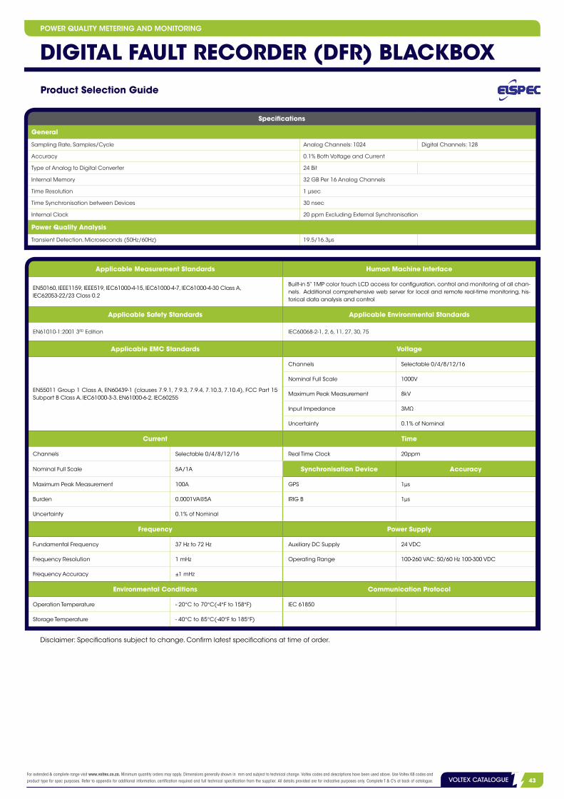
3VOLTEX CATALOGUEFor extended & complete range visit www.voltex.co.za. Minimum quantity orders may apply. Dimensions generally shown in mm and subject to technical change. Voltex codes and descriptions have been used above. Use Voltex K8 codes and product type for spec purposes. Refer to appendix for additional information, certification required and full technical specification from the supplier. All details provided are for indicative purposes only. Complete T & C's at back of catalogue. 43VOLTEX CATALOGUE
Specifications
General
Sampling Rate, Samples/Cycle Analog Channels: 1024 Digital Channels: 128
Accuracy 0.1% Both Voltage and Current
Type of Analog to Digital Converter 24 Bit
Internal Memory 32 GB Per 16 Analog Channels
Time Resolution 1 μsec
Time Synchronisation between Devices 30 nsec
Internal Clock 20 ppm Excluding External Synchronisation
Power Quality Analysis
Transient Detection, Microseconds (50Hz/60Hz) 19.5/16.3µs
Applicable Measurement Standards Human Machine Interface
EN50160, IEEE1159, IEEE519, IEC61000-4-15, IEC61000-4-7, IEC61000-4-30 Class A, IEC62053-22/23 Class 0.2
Built-in 5” 1MP color touch LCD access for configuration, control and monitoring of all chan-nels. Additional comprehensive web server for local and remote real-time monitoring, his-torical data analysis and control
Applicable Safety Standards Applicable Environmental Standards
EN61010-1:2001 3RD Edition IEC60068-2-1, 2, 6, 11, 27, 30, 75
Applicable EMC Standards Voltage
EN55011 Group 1 Class A, EN60439-1 (clauses 7.9.1, 7.9.3, 7.9.4, 7.10.3, 7.10.4), FCC Part 15 Subpart B Class A, IEC61000-3-3, EN61000-6-2, IEC60255
Channels Selectable 0/4/8/12/16
Nominal Full Scale 1000V
Maximum Peak Measurement 8kV
Input Impedance 3MΩ
Uncertainty 0.1% of Nominal
Current Time
Channels Selectable 0/4/8/12/16 Real Time Clock 20ppm
Nominal Full Scale 5A/1A Synchronisation Device Accuracy
Maximum Peak Measurement 100A GPS 1µs
Burden 0.0001VA@5A IRIG B 1µs
Uncertainty 0.1% of Nominal
Frequency Power Supply
Fundamental Frequency 37 Hz to 72 Hz Auxiliary DC Supply 24 VDC
Frequency Resolution 1 mHz Operating Range 100-260 VAC: 50/60 Hz 100-300 VDC
Frequency Accuracy ±1 mHz
Environmental Conditions Communication Protocol
Operation Temperature --20°C to 70°C(-4°F to 158°F) IEC 61850
Storage Temperature - 40°C to 85°C(-40°F to 185°F)
Product Selection Guide
Disclaimer: Specifications subject to change. Confirm latest specifications at time of order.
POWER QUALITY METERING AND MONITORING
DIGITAL FAULT RECORDER (DFR) BLACKBOX

facebook.com/VoltexSA | twitter.com/voltexsa
LSis Resin Transformers Power distribution, static converter,
traction application.
ENVIRONMENTALLY SAFE
LS Cast Resin Transformers will not emit oil or toxic gases into the atmosphere. Therefore, they do not pollute the environment and are strongly recommended as a replacement for askarel (PCB)-filled transformers.
Download our App at www.voltex.co.za orCABLE GLAND INDICATOR
iPhone is a trademark of Apple Inc. registered in the U.S. and other countries. Google play is a trademark of Google Inc.
Don’t forget to rate our App in your App Store.
• Low noise• Fire resistant• Moisture proof• Maintenance free• No partial discharge• High impulse strength• High overload capability• Standard IEC 60076-11
your electrical connectionwww.voltex.co.za [email protected]

3VOLTEX CATALOGUEFor extended & complete range visit www.voltex.co.za. Minimum quantity orders may apply. Dimensions generally shown in mm and subject to technical change. Voltex codes and descriptions have been used above. Use Voltex K8 codes and product type for spec purposes. Refer to appendix for additional information, certification required and full technical specification from the supplier. All details provided are for indicative purposes only. Complete T & C's at back of catalogue. 45VOLTEX CATALOGUE
NOTESPOWER OPTIMISATION

2 VOLTEX CATALOGUEFor extended & complete range visit www.voltex.co.za. Minimum quantity orders may apply. Dimensions generally shown in mm and subject to technical change. Voltex codes and descriptions have been used above. Use Voltex K8 codes and product type for spec purposes. Refer to appendix for additional information, certification required and full technical specification from the supplier. All details provided are for indicative purposes only. Complete T & C's at back of catalogue.46 VOLTEX CATALOGUE
NOTESPOWER OPTIMISATION
• Allimagesareforillustrationpurposesandmaydifferfromactualproducts.
• Despiteeveryeffortmadetoensuretheaccuracyofthetechnicalinformationinthiscatalogue,Voltexcannotbeheldliablefortheactualproductusedin
theinstallation,asthisvalidationwithregardstosuitabilityisentirelytheresponsibilityoftheinstaller.Voltexwillnotbeheldresponsibleforanyerrorsor
omissionsinthiscatalogue.
• Allproductsneedtobeinstalledbyanappropriatelyqualifiedelectrician/lawfullyqualifiedperson.
• Specificationsinthiscataloguearesubjecttochangewithoutnoticeduetocontinuousproductdevelopmentandimprovement.
• Duetomaterialandmanufacturingtolerances,testresultscanvaryperindividualproductorlengthofproduct.Accordingly,technicaldatashownistypical
andgivenforguidancepurposesonly.NowarrantyorguaranteecanbeofferedthattheinstalledproductwillmatchthetestresultsexactlyandVoltex
acceptsnoliabilityforproductsuppliednotmatchingthesestatedfigures.
• Ourproductsare,tothebestofourknowledge,freeofdefectatthetimeofshipment.Soleandexclusiveremedyislimited,atoursoleoption,torepairor
replaceproductssuppliedbyus.
• Liabilityisdisclaimedforanyincidentalorconsequentialdamage.
• Noliabilitywillbeassumedformisapplication,whichincludes:
-Useinnon-standard(aggressive/hostile)environments;
-Useonaluminiumorsimilarsofter‘fixto’materials;
-Overloadingoruseotherthanindicated.
• Whilestockslast.
• Nothinginthiscatalogueoranypartthereofmaybeconstruedasanoffertosupplyorsellanyproducttoanyperson,orasaninducementoroffertoany
persontoenterintoacontractwithVoltexinrespectofthesupplyofanyproduct.
• Subjecttoallapplicablelaw,Voltex:
-Acceptsnoresponsibilityforanylossordamage,ofwhatsoevernature,arisinginanywayoutoftheuseoforrelianceoninformationcontainedin
thiscatalogue;
-Makesnorepresentationsastotheavailabilityofanyproductandreservestherighttomodifyordiscontinueaproductwithoutnotice,andtochange
productspecificationsanddescriptionswithoutnotice;
-Acceptsnoresponsibilityformisprints,errors,omissionsorinaccuraciesinthiscatalogue;
-Makesnowarranties,expressorimplied,inthiscatalogue:
•Asthefeaturesandcoloursofaproductmaybereproducedinexactlyinthephotographyprocess,thiscatalogueismerelyaguide;
•Allrightsarefullyreserved.Nopartofthispublication(includingthetextandimages)maybemodified,copied,reproduced,storedina
retrievalsystem,transmittedordistributedinanyformorbyanymeans(whetherelectronic,mechanical,photocopyingorotherwise),without
theprior,expresswrittenpermissionofVoltex.
Disclaimer

DISCLAIMER• Forthefulldisclaimerseeinside.
!2014/08
VOLTEX BRANCHES NATIONWIDEEASTERN CAPE PROVINCERonny Landman Tel: +27 (43) 743 3650 +27 (43) 743 5201
FREE STATE PROVINCEAndre De La Guerre Tel: +27 (53) 712 1164 +27 (53) 712 3291
Jaco NieuwoudtTel: +27 (53) 712 1164 +27 (53) 712 3291
GAUTENG PROVINCELee Orren Tel: +27 (12) 330 0211 +27 (12) 330 0220
Johan HattinghTel: +27 (11) 314 0620/1
KWA-ZULU NATAL PROVINCERakesh Heeralal Tel: +27 (31) 573 9373
Gerald ColemanTel: +27 (31) 573 9373
LIMPOPO PROVINCEHarry Visage Tel: +27 (15) 307 1213/4
MPUMALANGA PROVINCESmiley Van Der Watt Tel: +27 (13) 753 3641/2/3/4 +27 (13) 753 2682/3/4
NORTH WEST PROVINCEAndre De La Guerre Tel: +27 (53) 712 1164 +27 (53) 712 3291
Jaco NieuwoudtTel: +27 (53) 712 1164 +27 (53) 712 3291
NORTHERN CAPE PROVINCEAndre De La Guerre Tel: +27 (53) 712 1164 +27 (53) 712 3291
Jaco NieuwoudtTel: +27 (53) 712 1164 +27 (53) 712 3291
WESTERN CAPE PROVINCEDean Martch Tel: +27 (21) 531 2033
Fred WilsonTel: +27 (21) 440 7100
VERSION – PO SF 1
www.voltex.co.za facebook.com/VoltexSA | twitter.com/voltexsa
your electrical connection