Piling Works- requirements on piling plan submission
80
1 Er Dr Yet Nai Song Building and Construction Authority Requirements on piling plan submission Under BC (Amendment) Act 2007 & Regulations 2008
Transcript of Piling Works- requirements on piling plan submission
1
Er Dr Yet Nai SongBuilding and Construction Authority
Requirements on piling plan submission
Under BC (Amendment) Act 2007 & Regulations 2008
2
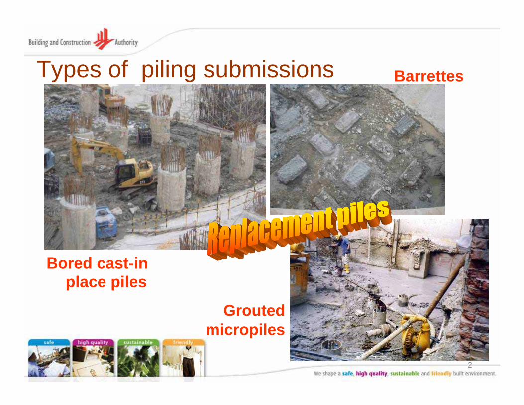
Types of piling submissions
Bored cast-in place piles
Barrettes
Grouted micropiles
3
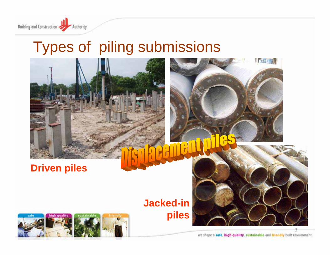
Types of piling submissions
Driven piles
Jacked-in piles

4
Objective• To help Qualified Persons who
prepare the piling plans to comply with requirements of BC (Amendment) Act 2007 & Regulations 2008
5
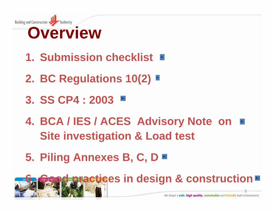
Overview1. Submission checklist
2. BC Regulations 10(2)
3. SS CP4 : 2003
4. BCA / IES / ACES Advisory Note on Site investigation & Load test
5. Piling Annexes B, C, D
6. Good practices in design & construction
6
(1) Submission checklist
7
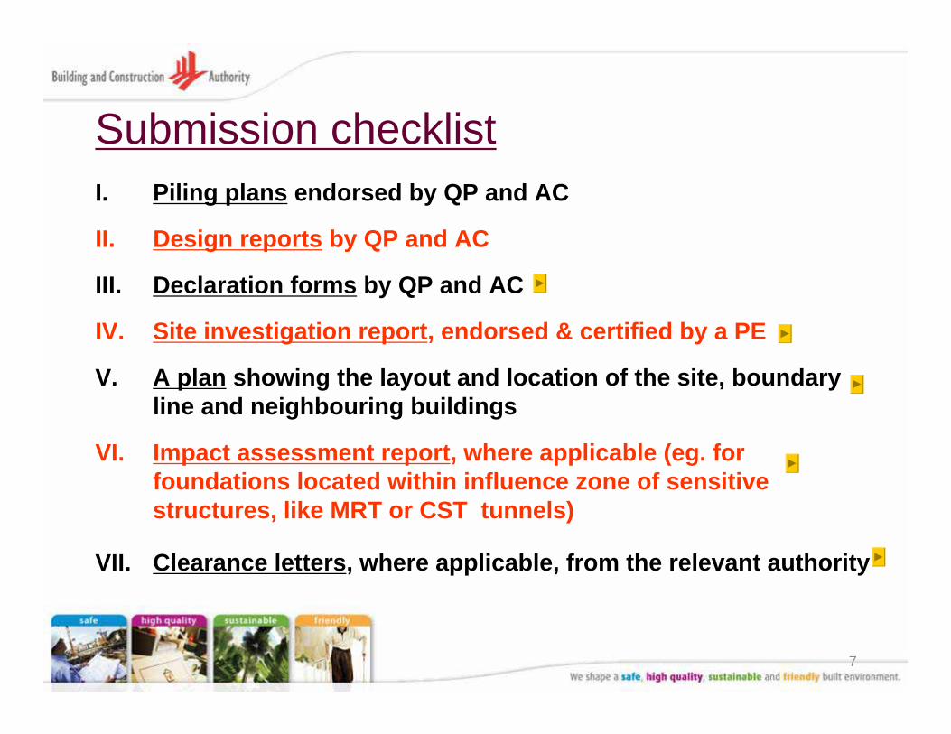
Submission checklistI. Piling plans endorsed by QP and AC
II. Design reports by QP and AC
III. Declaration forms by QP and AC
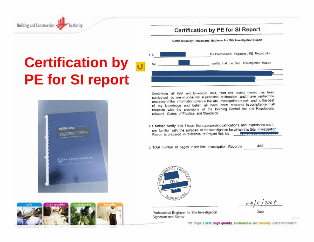
IV. Site investigation report, endorsed & certified by a PE
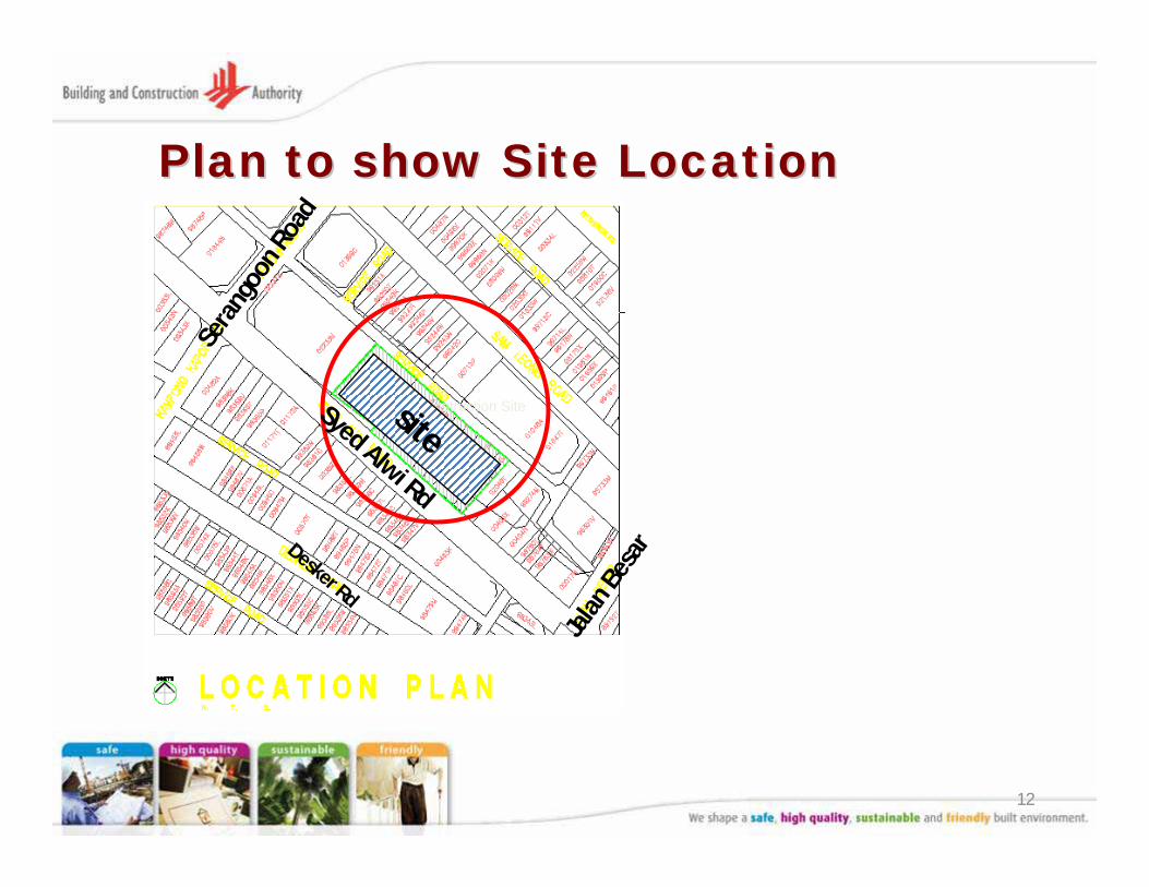
V. A plan showing the layout and location of the site, boundary line and neighbouring buildings
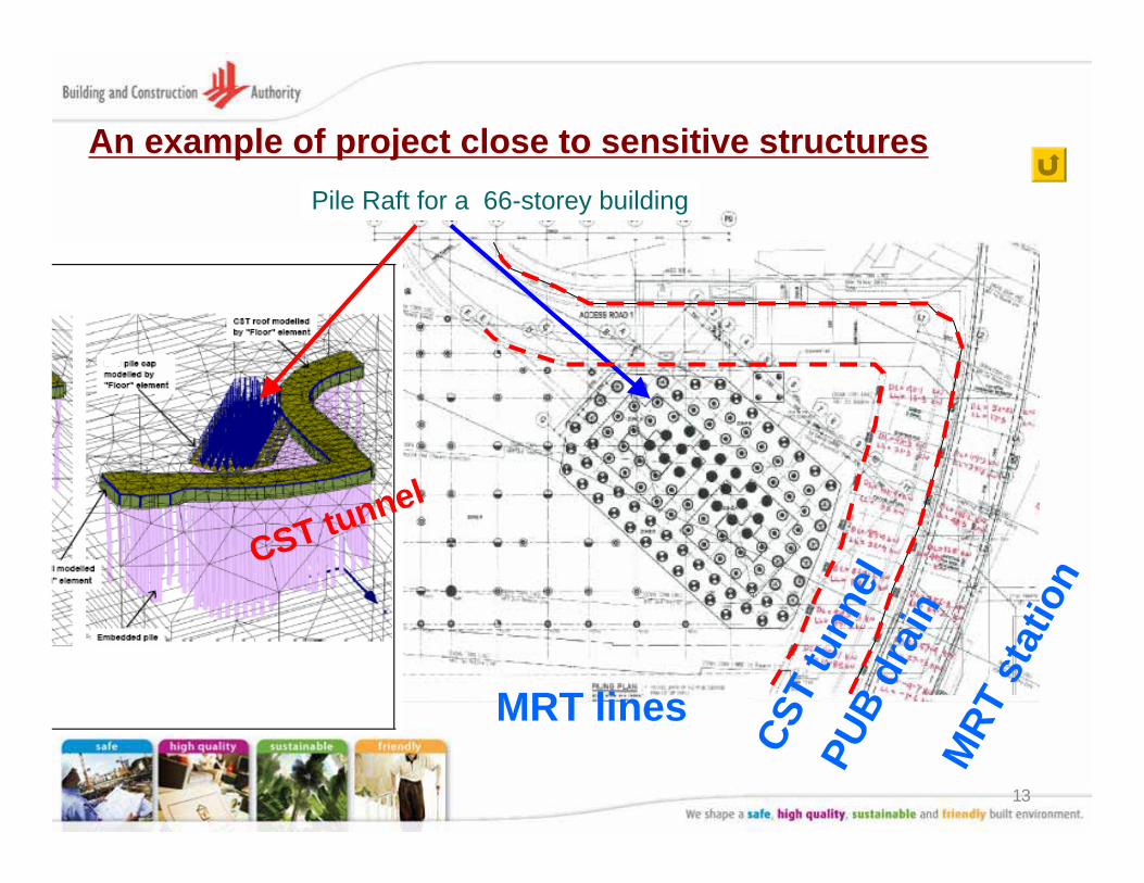
VI. Impact assessment report, where applicable (eg. for foundations located within influence zone of sensitive structures, like MRT or CST tunnels)
VII. Clearance letters, where applicable, from the relevant authority
8
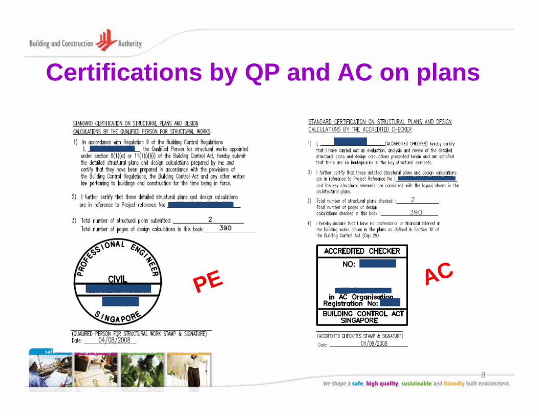
Certifications by QP and AC on plans
ACPE

9
Certifications by QP(geo) and AC(geo) on plans
AC(geo)
PE(geo)
10
11
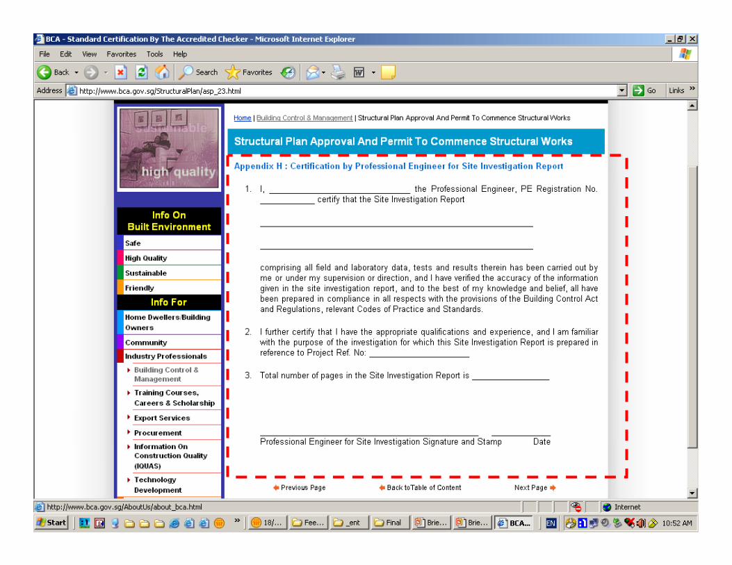
Certification by PE for SI report
12
Plan to show Site LocationPlan to show Site Location
Proposed Construction SiteSyed Alwi Rd
Desker RdJa
lan
Besa
r
site
Sera
ngoo
nRo
ad
13
An example of project close to sensitive structures
CST
tunn
el
Pile Raft for a 66-storey building
PUB
drai
nM
RT s
tatio
n
CST tunnel
MRT lines
14
(2) Building Control Regulation 10(2)
15
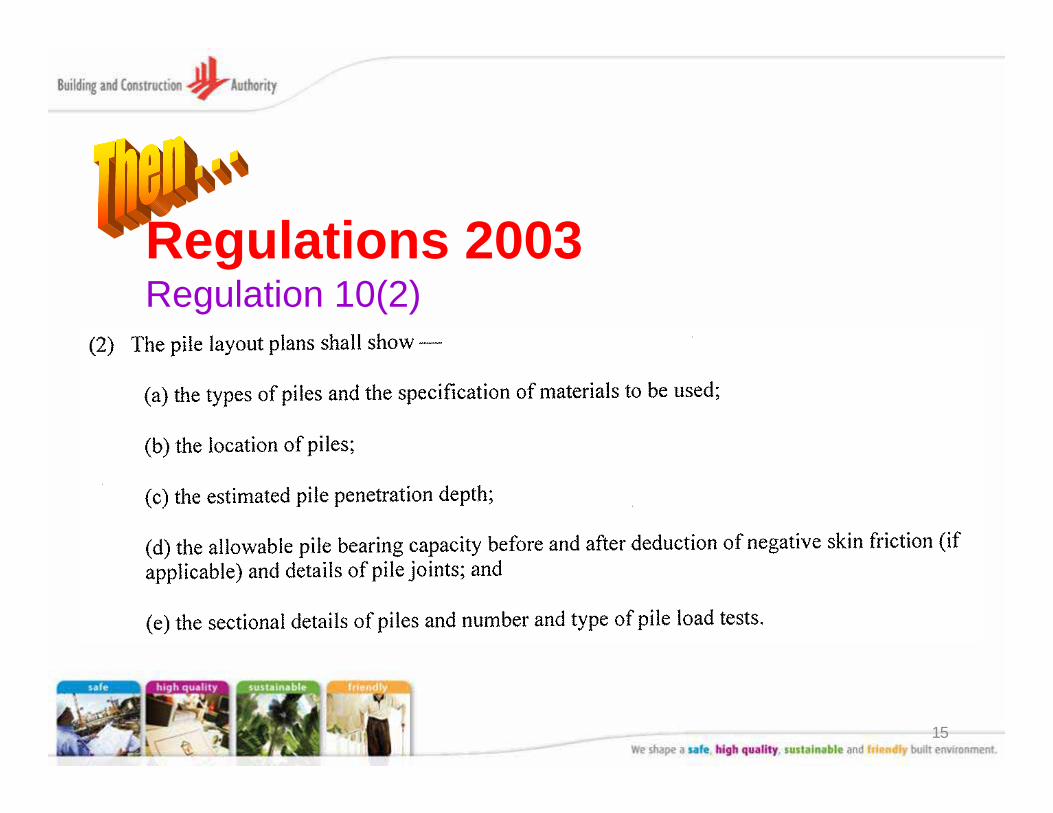
Regulations 2003Regulation 10(2)
16
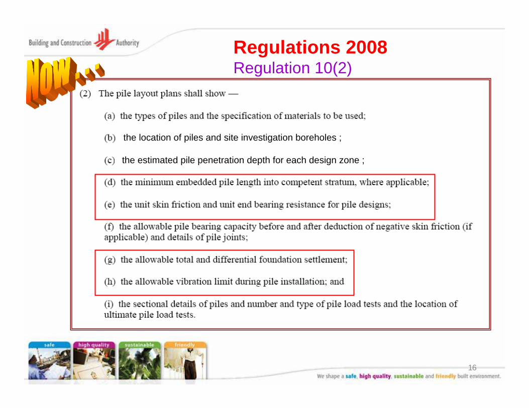
Regulations 2008Regulation 10(2)
the estimated pile penetration depth for each design zone ;
the location of piles and site investigation boreholes ;
17
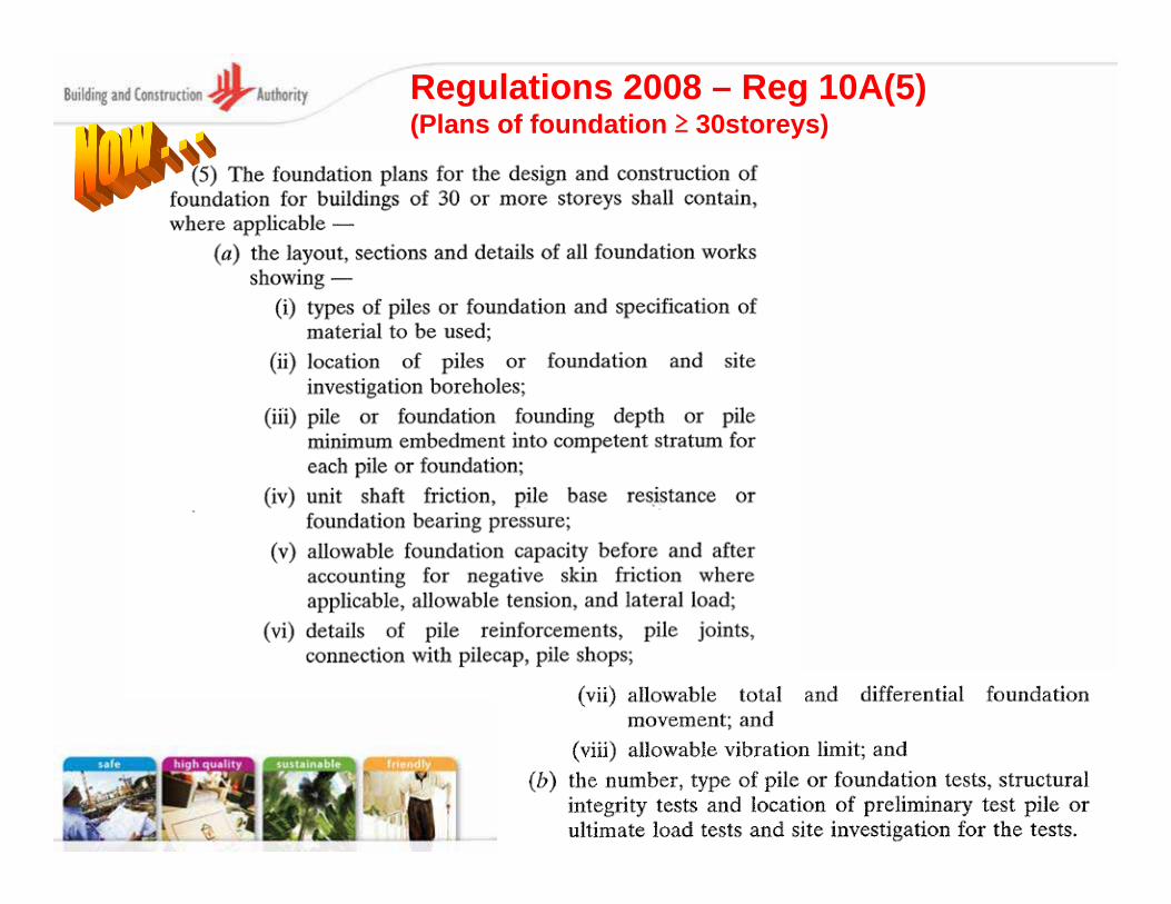
Regulations 2008 – Reg 10A(5)(Plans of foundation ≥ 30storeys)
18
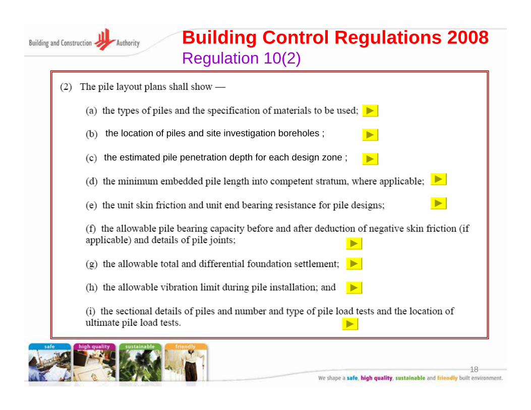
Building Control Regulations 2008Regulation 10(2)
the estimated pile penetration depth for each design zone ;
the location of piles and site investigation boreholes ;
19
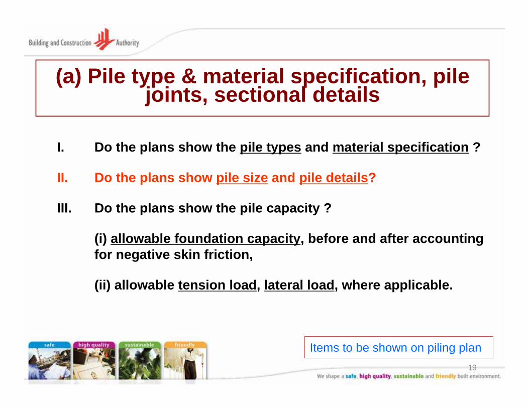
(a) Pile type & material specification, pile joints, sectional details
I. Do the plans show the pile types and material specification ?
II. Do the plans show pile size and pile details?
III. Do the plans show the pile capacity ?
(i) allowable foundation capacity, before and after accounting for negative skin friction,
(ii) allowable tension load, lateral load, where applicable.
Items to be shown on piling plan
20
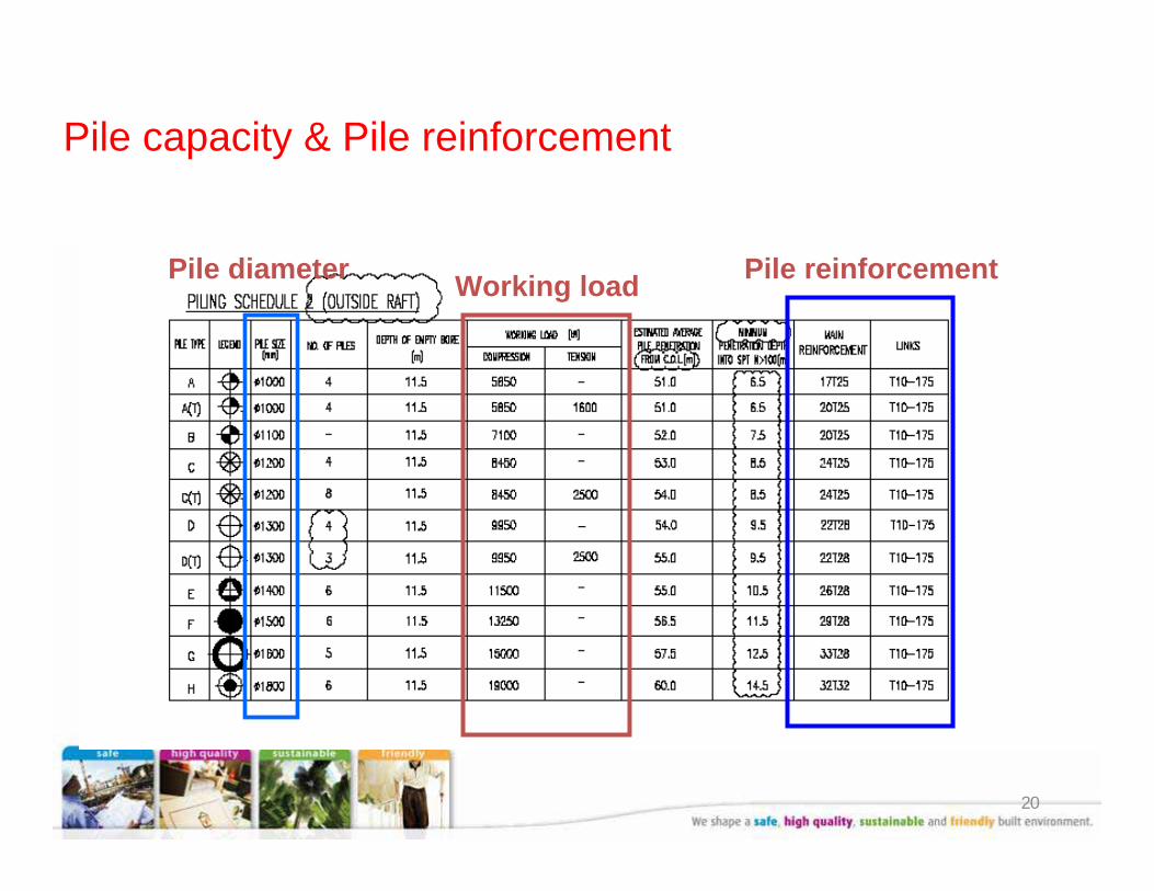
Pile capacity & Pile reinforcement
Pile diameter Working load Pile reinforcement
21
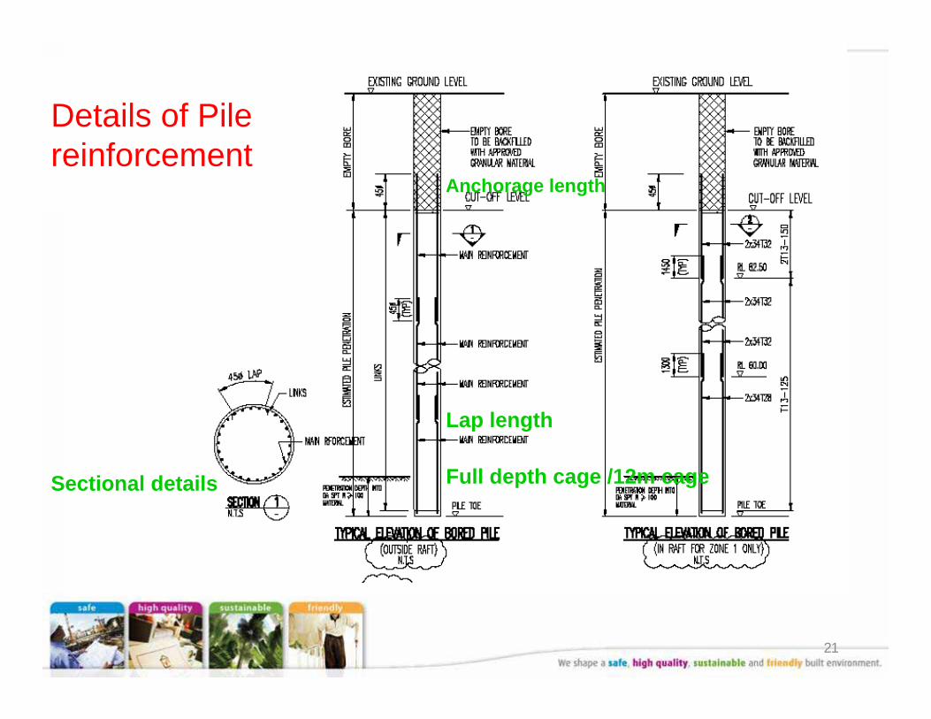
Details of Pile reinforcement
Anchorage length
Lap length
Full depth cage /12m cageSectional details
22
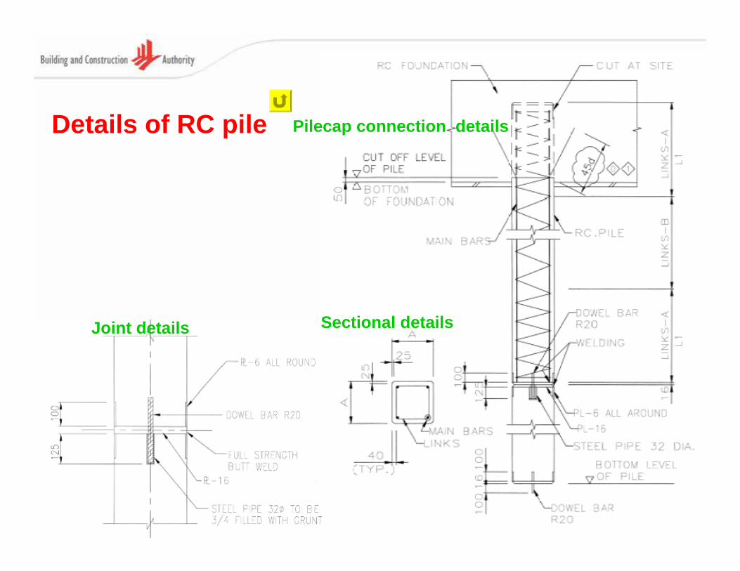
Details of RC pile
Sectional detailsJoint details
Pilecap connection details
23
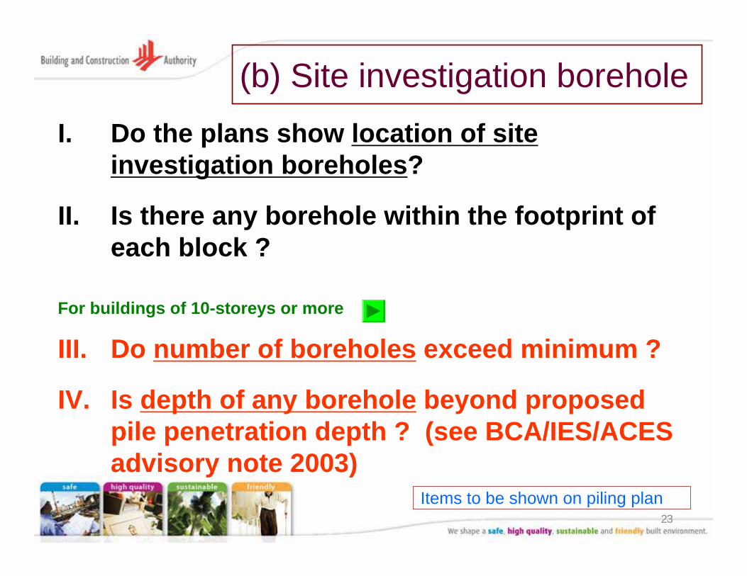
(b) Site investigation boreholeI. Do the plans show location of site
investigation boreholes?
II. Is there any borehole within the footprint of each block ?
III. Do number of boreholes exceed minimum ?
IV. Is depth of any borehole beyond proposed pile penetration depth ? (see BCA/IES/ACES advisory note 2003)
Items to be shown on piling plan
For buildings of 10-storeys or more
24
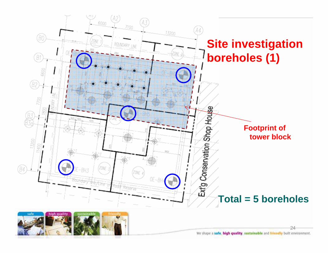
Site investigation boreholes (1)
Footprint of tower block
Total = 5 boreholes
25
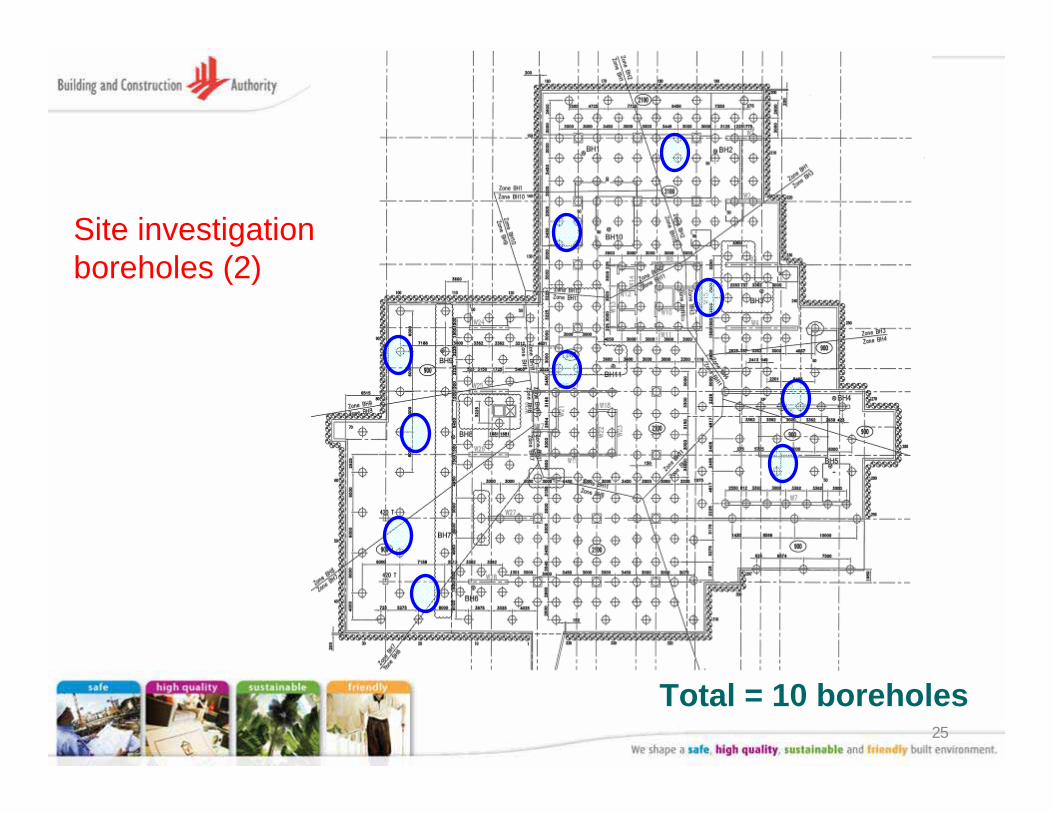
Total = 10 boreholes
Site investigation boreholes (2)
26
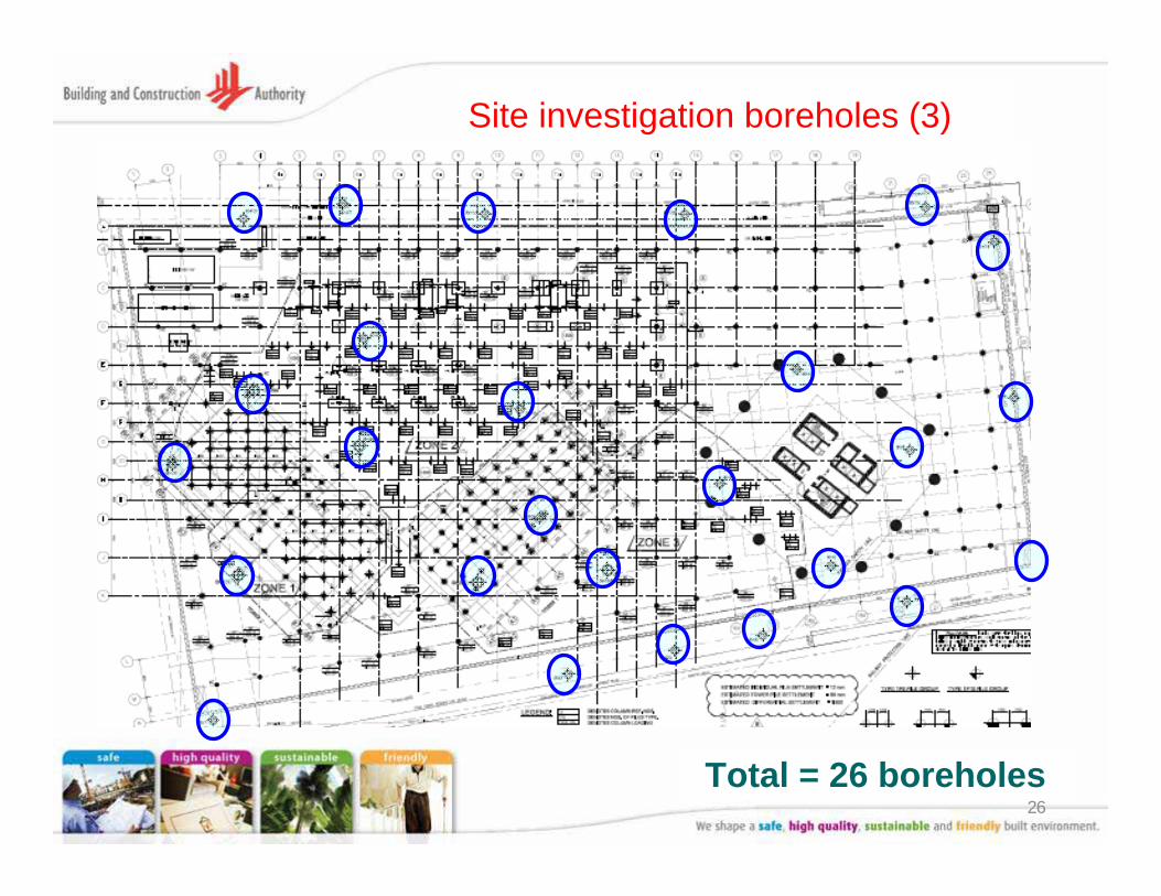
Site investigation boreholes (3)
Total = 26 boreholes
27
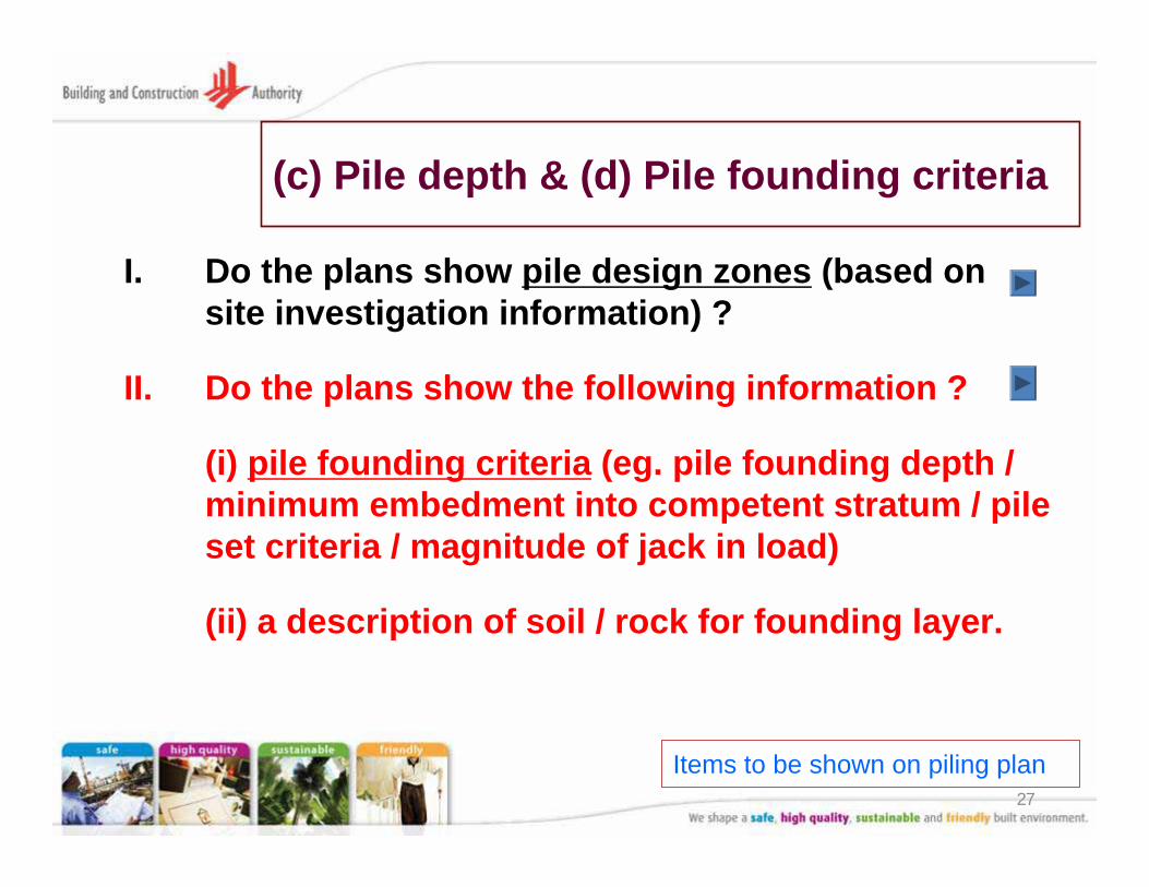
(c) Pile depth & (d) Pile founding criteria
I. Do the plans show pile design zones (based on site investigation information) ?
II. Do the plans show the following information ?
(i) pile founding criteria (eg. pile founding depth / minimum embedment into competent stratum / pile set criteria / magnitude of jack in load)
(ii) a description of soil / rock for founding layer.
Items to be shown on piling plan
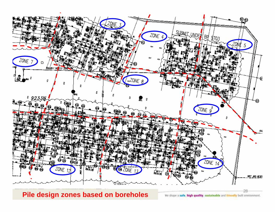
28Pile design zones based on boreholes
29
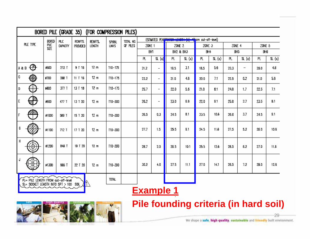
Example 1Pile founding criteria (in hard soil)
30
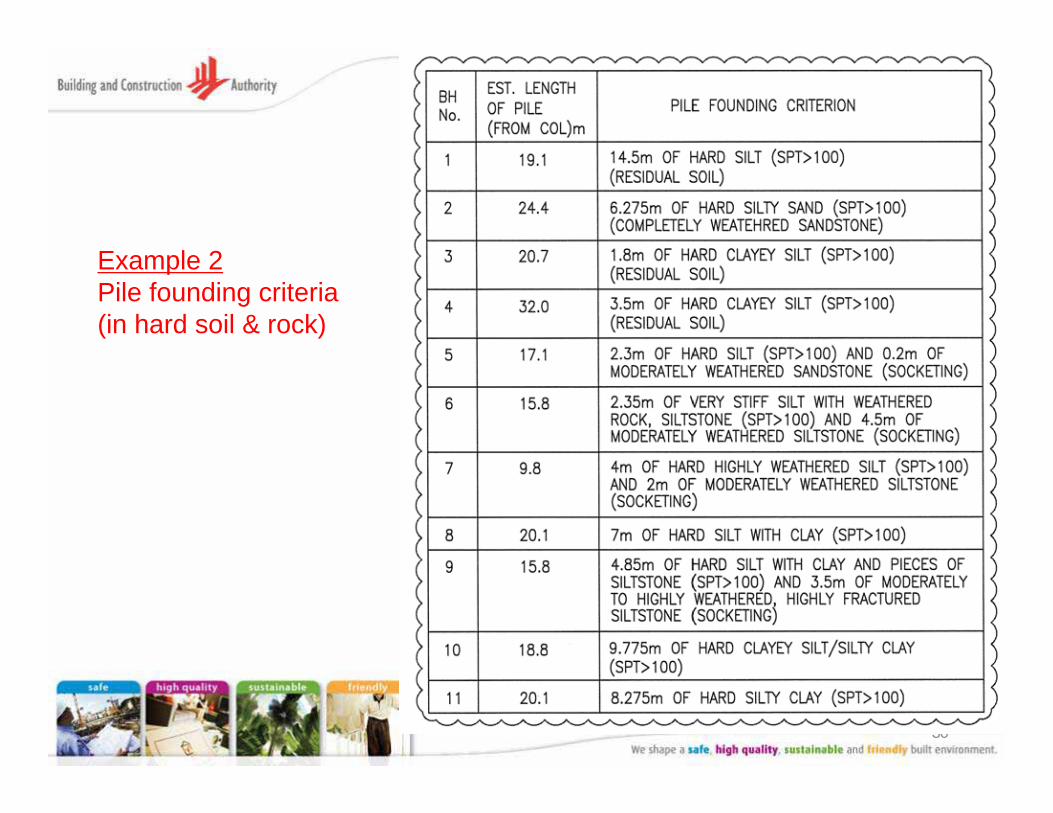
Example 2Pile founding criteria (in hard soil & rock)
31
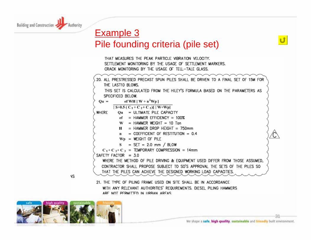
Example 3Pile founding criteria (pile set)
32
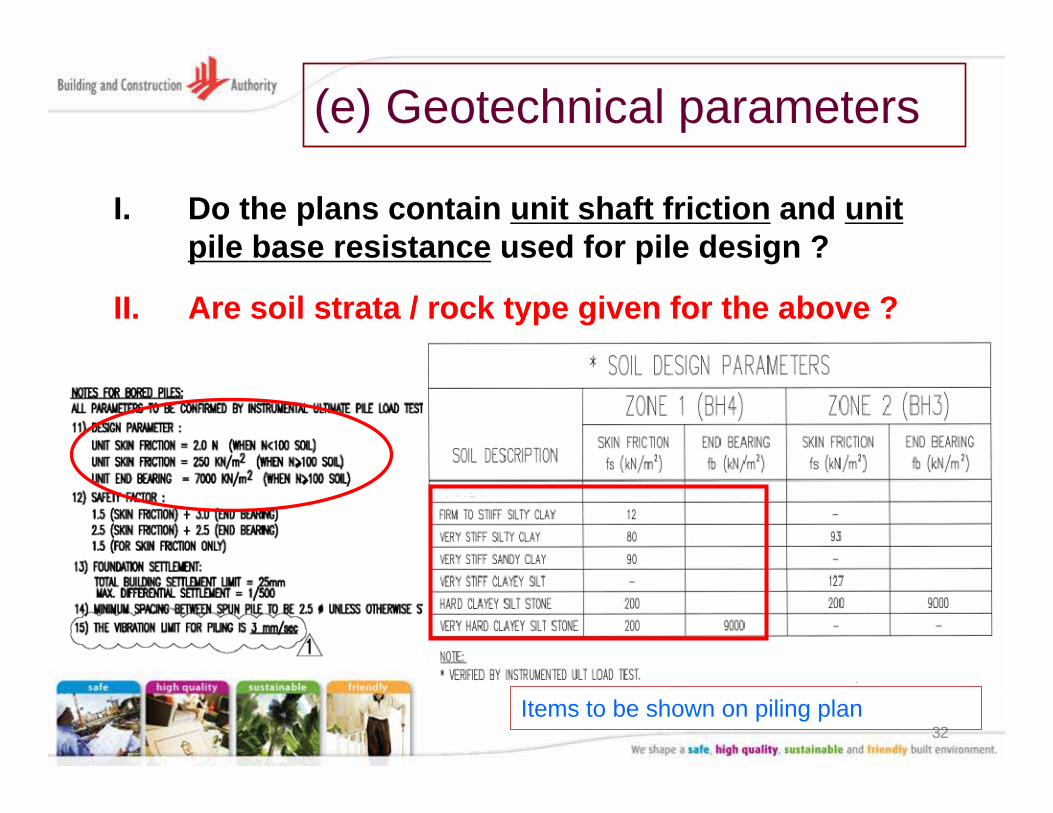
(e) Geotechnical parameters
I. Do the plans contain unit shaft friction and unit pile base resistance used for pile design ?
II. Are soil strata / rock type given for the above ?
Items to be shown on piling plan
33
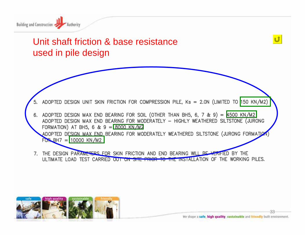
Unit shaft friction & base resistance used in pile design
34
(f) Negative skin friction
I. Is there a design evaluation of the possibility of negative skin friction ?
(i.e. whether the soil is still undergoing consolidation at its final stress state ?)
II. Has negative skin friction been considered in the design ?
Items to be shown on piling plan
35
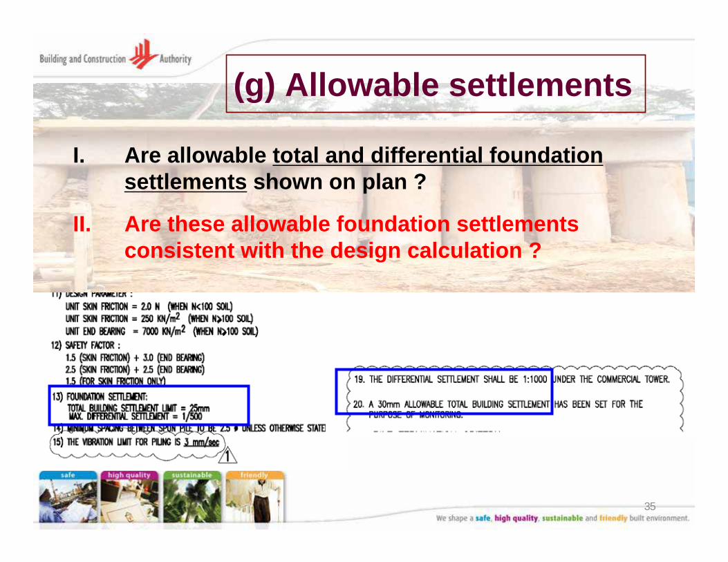
(g) Allowable settlements
I. Are allowable total and differential foundation settlements shown on plan ?
II. Are these allowable foundation settlements consistent with the design calculation ?
36
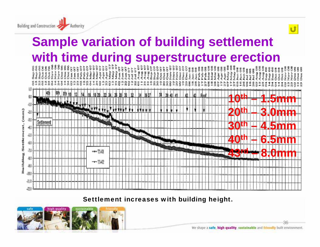
Sample variation of building settlement with time during superstructure erection
Settlement increases with building height.
10th – 1.5mm20th – 3.0mm30th – 4.5mm40th – 6.5mm43rd – 8.0mm
37
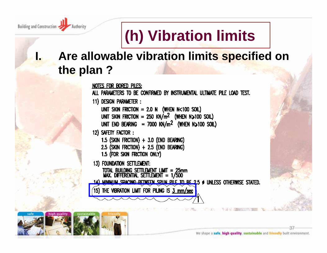
(h) Vibration limitsI. Are allowable vibration limits specified on
the plan ?
38
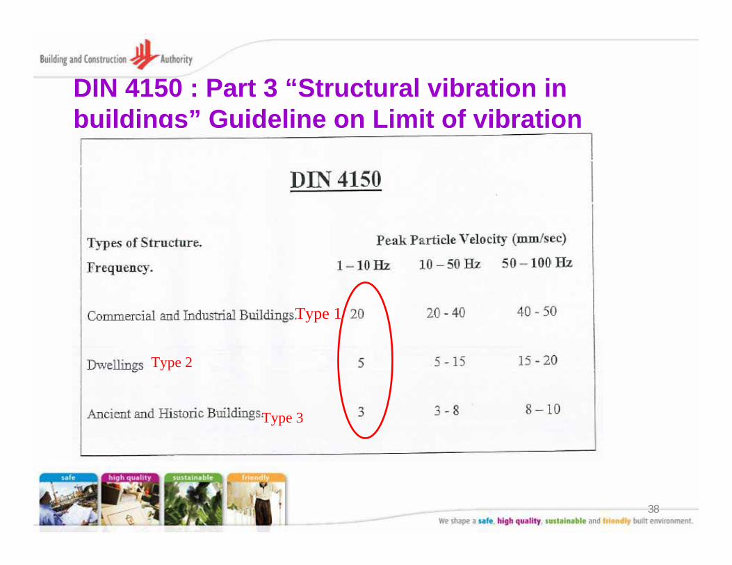
DIN 4150 : Part 3 “Structural vibration in buildings” Guideline on Limit of vibration
Type 1
Type 2
Type 3
39
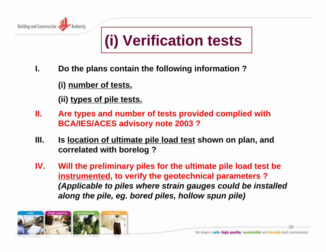
(i) Verification tests
I. Do the plans contain the following information ?
(i) number of tests,
(ii) types of pile tests.
II. Are types and number of tests provided complied with BCA/IES/ACES advisory note 2003 ?
III. Is location of ultimate pile load test shown on plan, and correlated with borelog ?
IV. Will the preliminary piles for the ultimate pile load test be instrumented, to verify the geotechnical parameters ? (Applicable to piles where strain gauges could be installed along the pile, eg. bored piles, hollow spun pile)
40
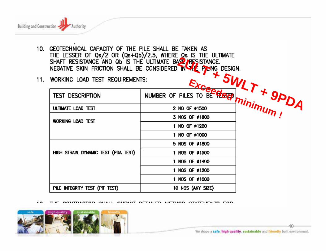
2ULT + 5WLT + 9PDAExceeded minimum !
41
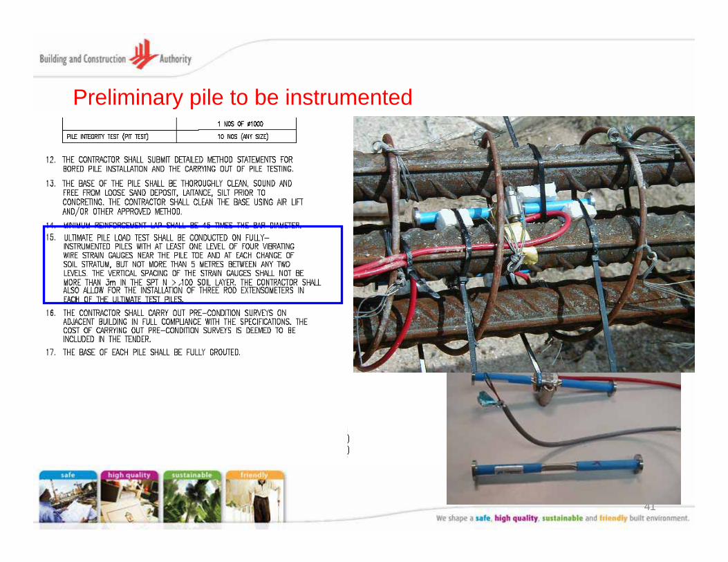
Preliminary pile to be instrumented
42
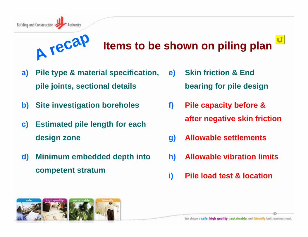
Items to be shown on piling plan
a) Pile type & material specification,
pile joints, sectional details
b) Site investigation boreholes
c) Estimated pile length for each
design zone
d) Minimum embedded depth into
competent stratum
e) Skin friction & End
bearing for pile design
f) Pile capacity before &
after negative skin friction
g) Allowable settlements
h) Allowable vibration limits
i) Pile load test & location
A recap

43
(3) SS CP4 : 2003
(Code of Practice for Foundations)
44
Code of Practice CP4 : 2003
45
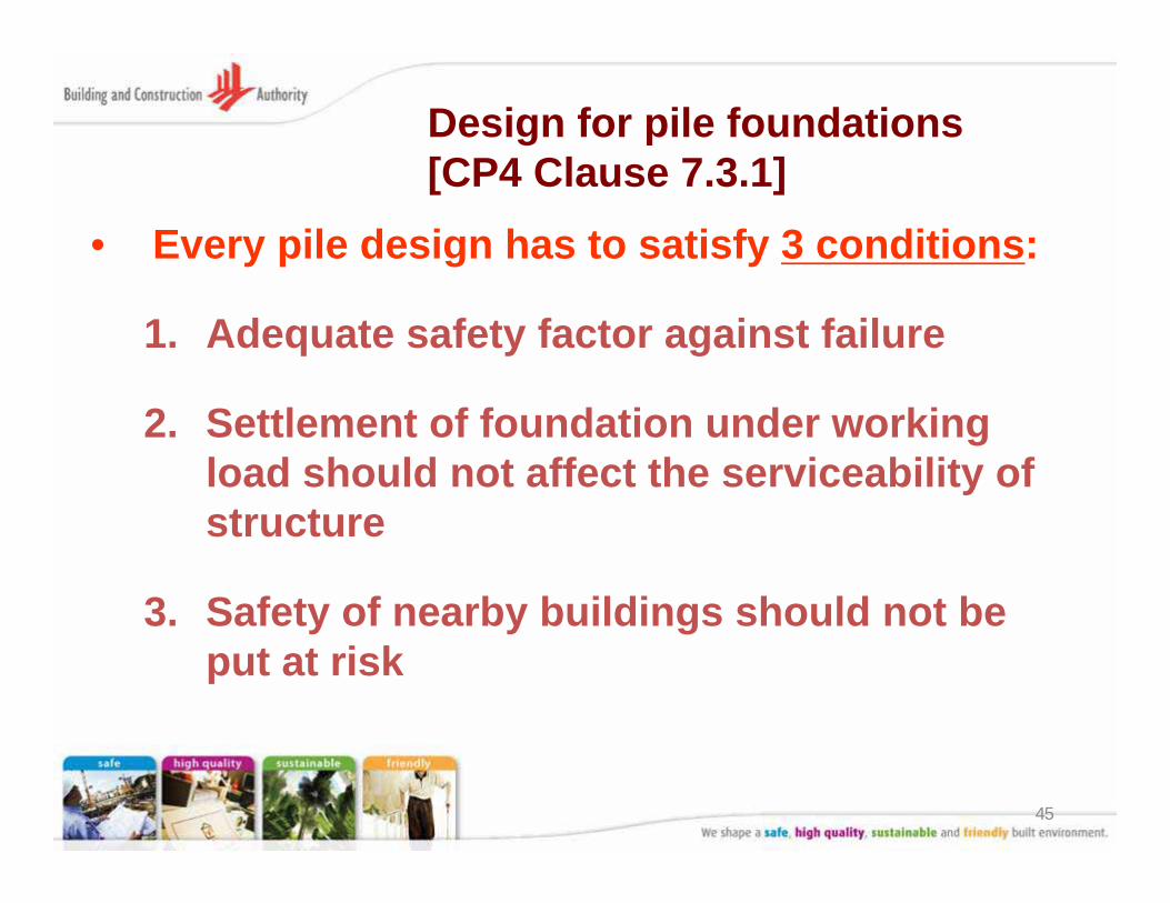
Design for pile foundations[CP4 Clause 7.3.1]
• Every pile design has to satisfy 3 conditions:
1. Adequate safety factor against failure
2. Settlement of foundation under working load should not affect the serviceability of structure
3. Safety of nearby buildings should not be put at risk
46
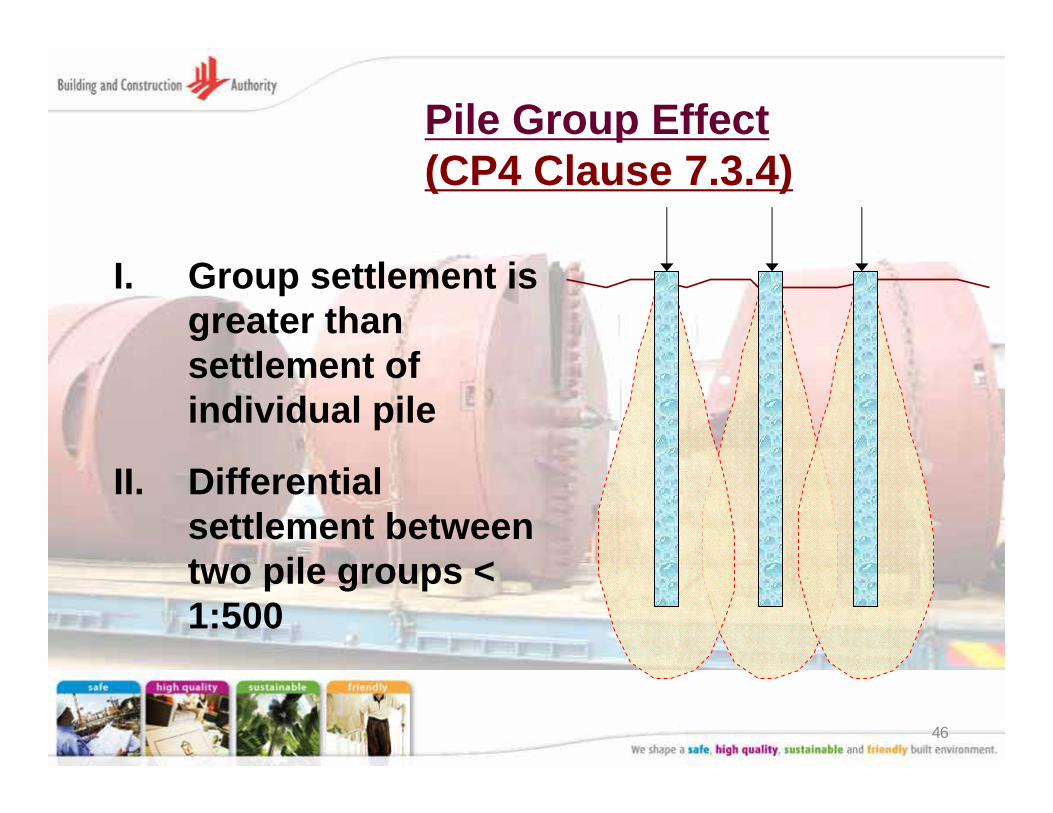
Pile Group Effect(CP4 Clause 7.3.4)
I. Group settlement is greater than settlement of individual pile
II. Differential settlement between two pile groups < 1:500
47
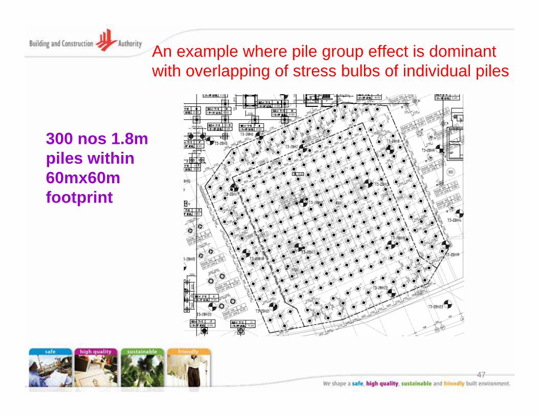
300 nos 1.8m piles within 60mx60m footprint
An example where pile group effect is dominant with overlapping of stress bulbs of individual piles
48
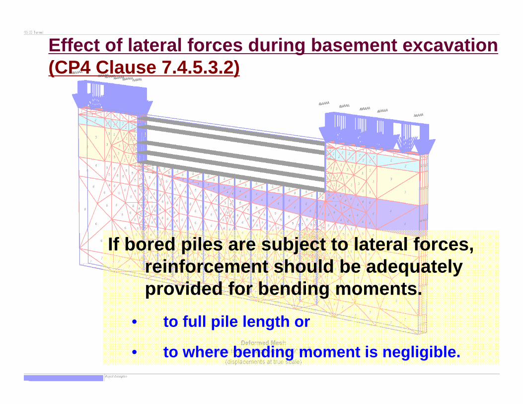
Effect of lateral forces during basement excavation(CP4 Clause 7.4.5.3.2)
If bored piles are subject to lateral forces, reinforcement should be adequately provided for bending moments.
• to full pile length or
• to where bending moment is negligible.
49
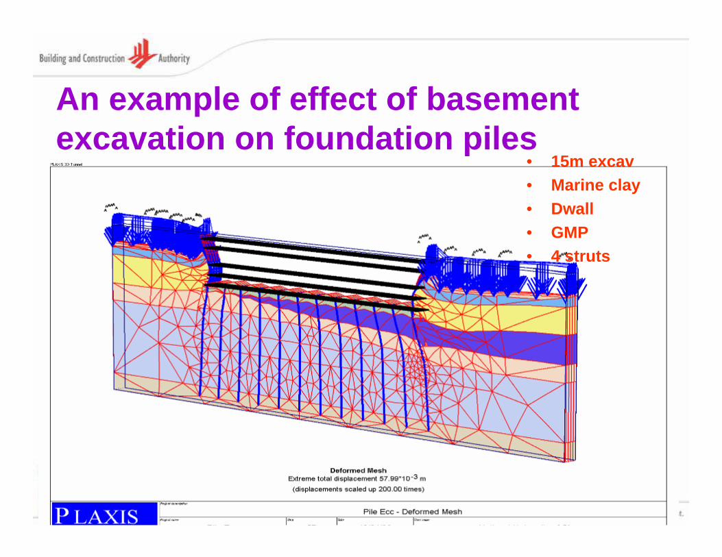
An example of effect of basement excavation on foundation piles
• 15m excav• Marine clay• Dwall• GMP• 4 struts
50
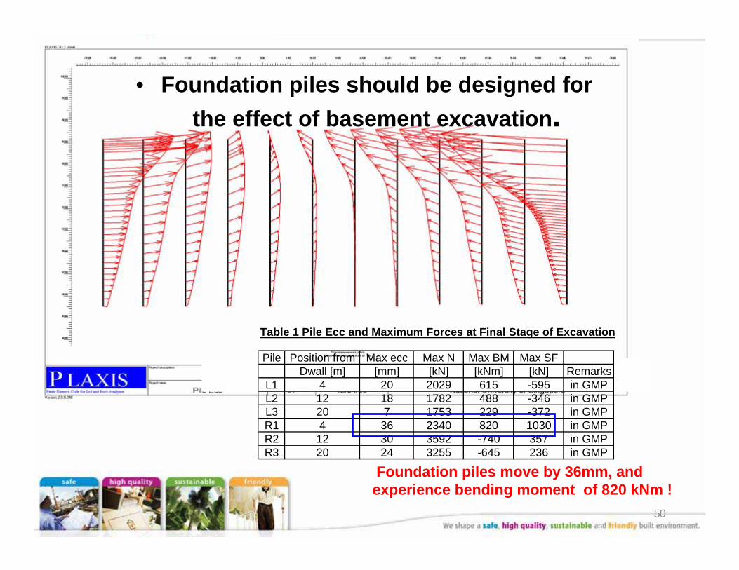
Table 1 Pile Ecc and Maximum Forces at Final Stage of Excavation
Pile Position from Max ecc Max N Max BM Max SFDwall [m] [mm] [kN] [kNm] [kN] Remarks
L1 4 20 2029 615 -595 in GMPL2 12 18 1782 488 -346 in GMPL3 20 7 1753 229 -372 in GMPR1 4 36 2340 820 1030 in GMPR2 12 30 3592 -740 357 in GMPR3 20 24 3255 -645 236 in GMP
Foundation piles move by 36mm, and experience bending moment of 820 kNm !
• Foundation piles should be designed for the effect of basement excavation.
51
(4) BCA / IES / ACES Advisory note
(for buildings of 10-storeys or more)
52
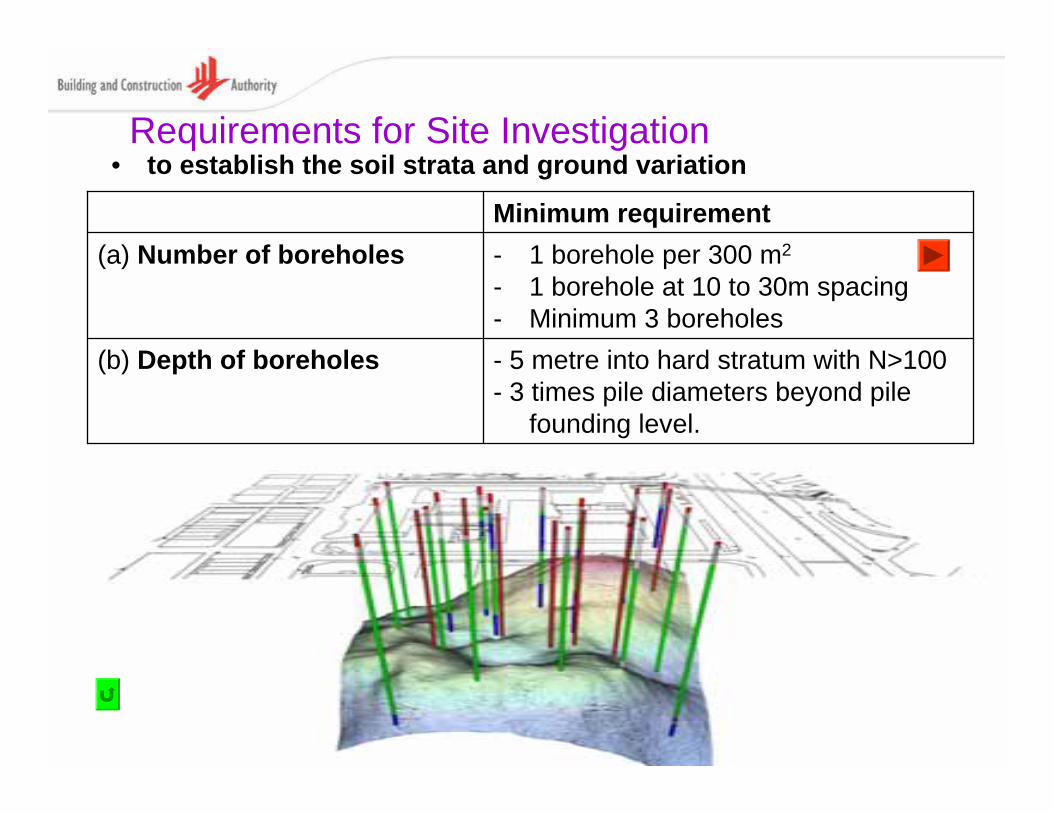
Requirements for Site Investigation
- 5 metre into hard stratum with N>100- 3 times pile diameters beyond pile
founding level.
(b) Depth of boreholes
- 1 borehole per 300 m2
- 1 borehole at 10 to 30m spacing- Minimum 3 boreholes
(a) Number of boreholesMinimum requirement
• to establish the soil strata and ground variation
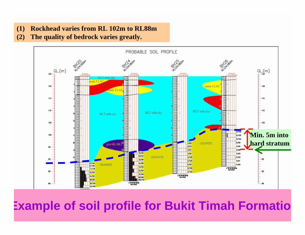
53Example of soil profile for Bukit Timah Formatio
(1) Rockhead varies from RL 102m to RL88m(2) The quality of bedrock varies greatly.
Min. 5m into hard stratum
54
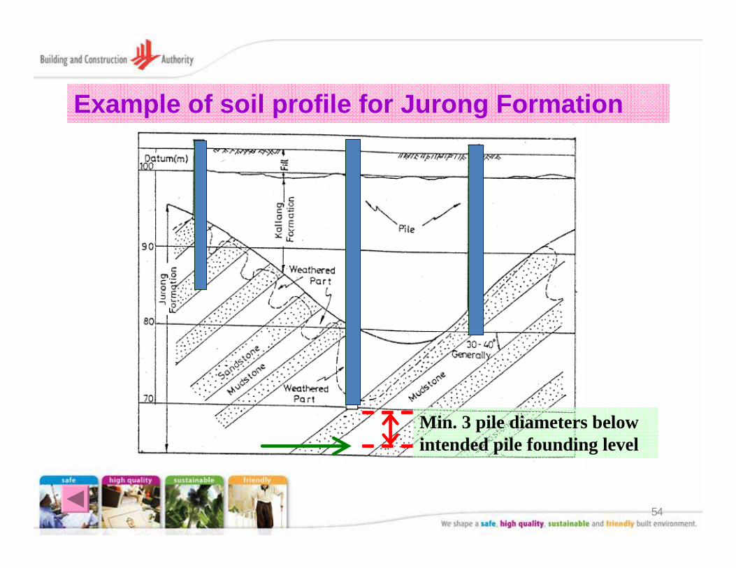
Example of soil profile for Jurong Formation
Min. 3 pile diameters below intended pile founding level
55
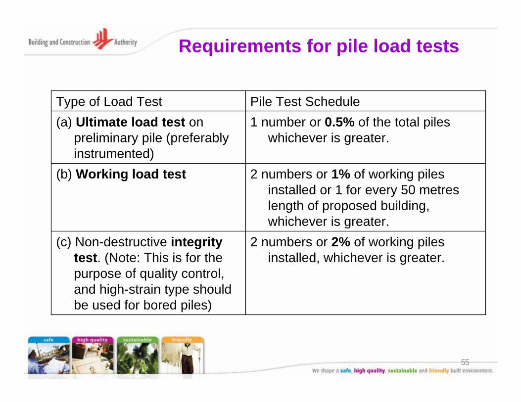
Requirements for pile load tests
2 numbers or 2% of working piles installed, whichever is greater.
(c) Non-destructive integrity test. (Note: This is for the purpose of quality control, and high-strain type should be used for bored piles)
2 numbers or 1% of working piles installed or 1 for every 50 metreslength of proposed building, whichever is greater.
(b) Working load test
1 number or 0.5% of the total piles whichever is greater.
(a) Ultimate load test on preliminary pile (preferably instrumented)
Pile Test ScheduleType of Load Test
56
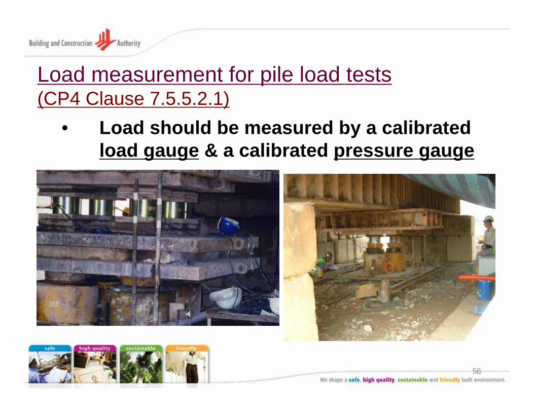
Load measurement for pile load tests(CP4 Clause 7.5.5.2.1)
• Load should be measured by a calibrated load gauge & a calibrated pressure gauge
57
(5) Piling Annexes
(for buildings of 10-storeys or more)
58
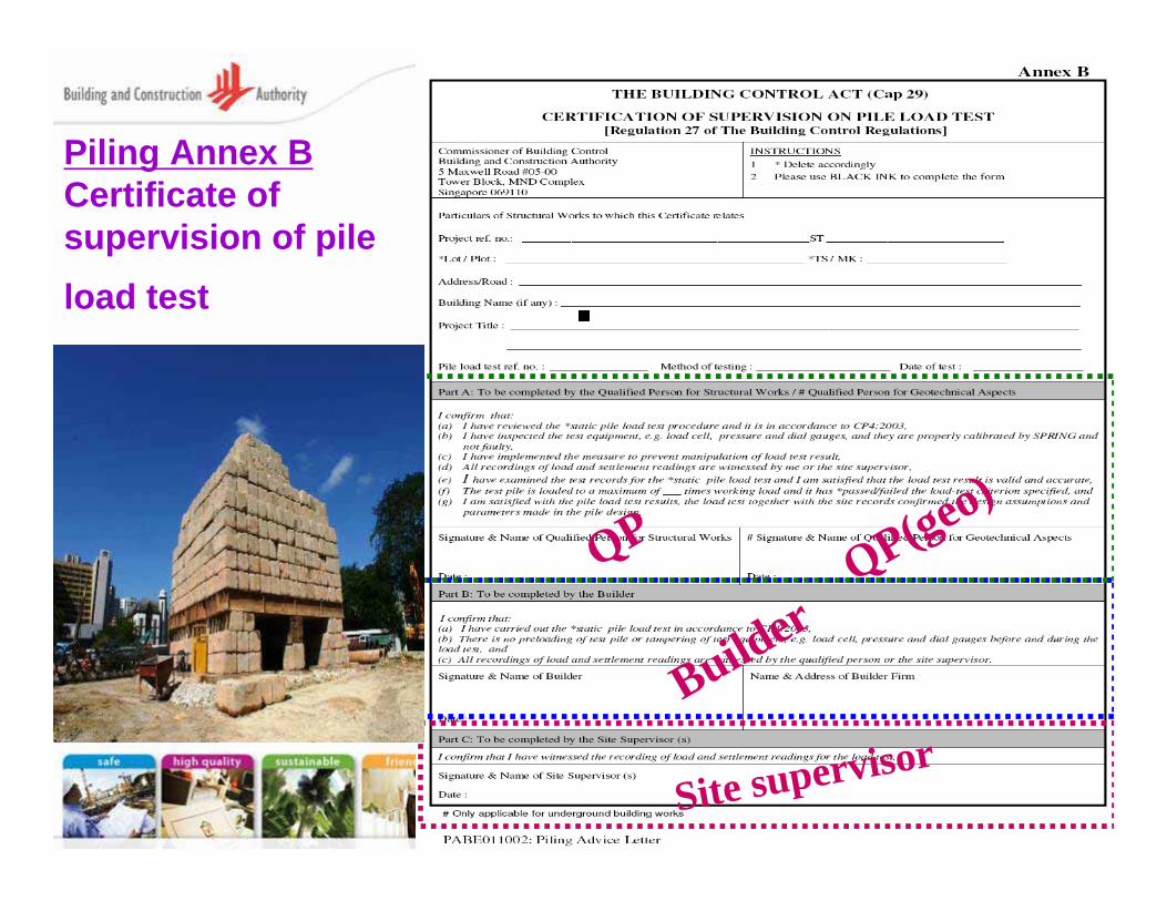
Piling Annex BCertificate of supervision of pile load test
QP
Builder
Site supervisor
QP(geo)
59
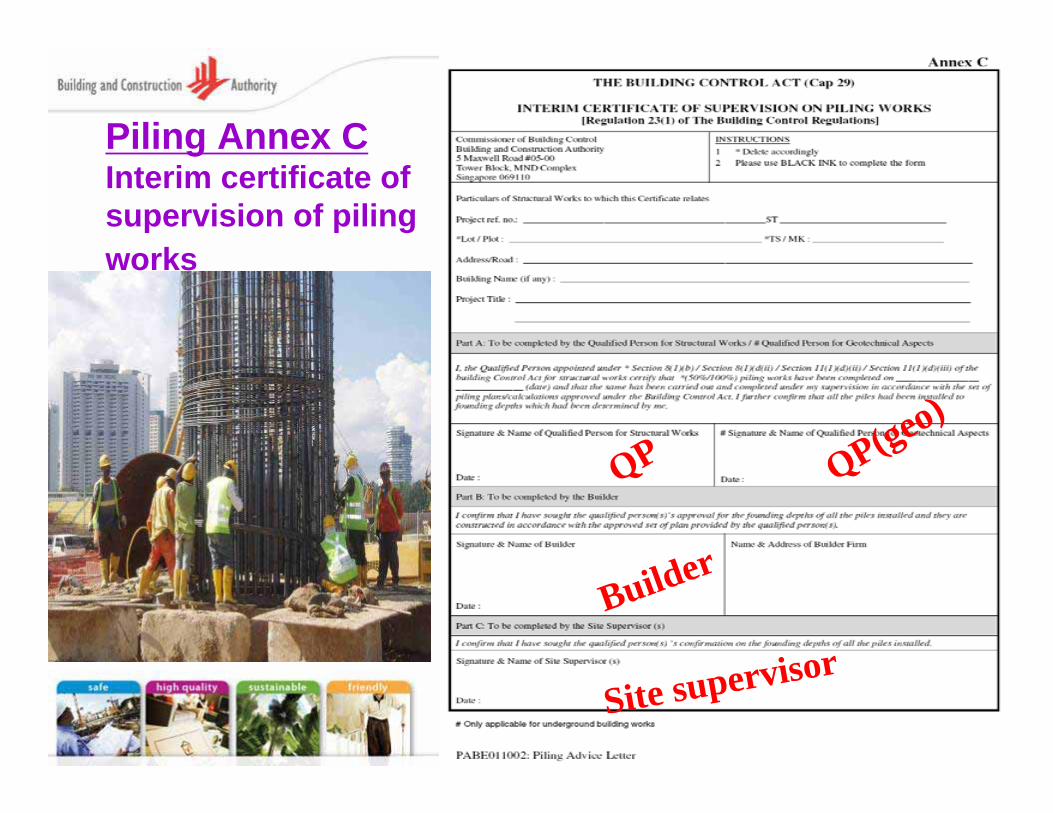
Piling Annex CInterim certificate of supervision of piling works
QP
Builder
Site supervisor
QP(geo)
60
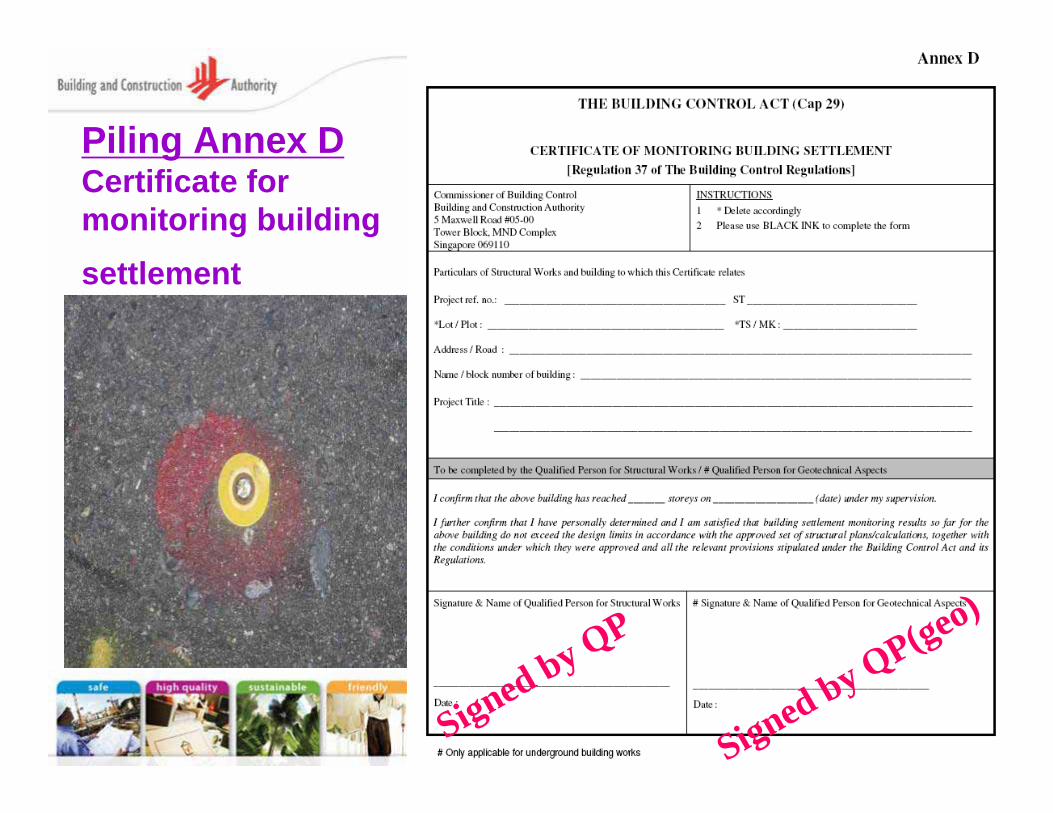
Piling Annex DCertificate for monitoring building settlement
Signed by QP
Signed by QP(geo)

61
(6) Some good practices in pile design & construction
62
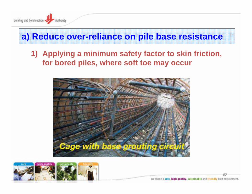
a) Reduce over-reliance on pile base resistance
1) Applying a minimum safety factor to skin friction, for bored piles, where soft toe may occur
63
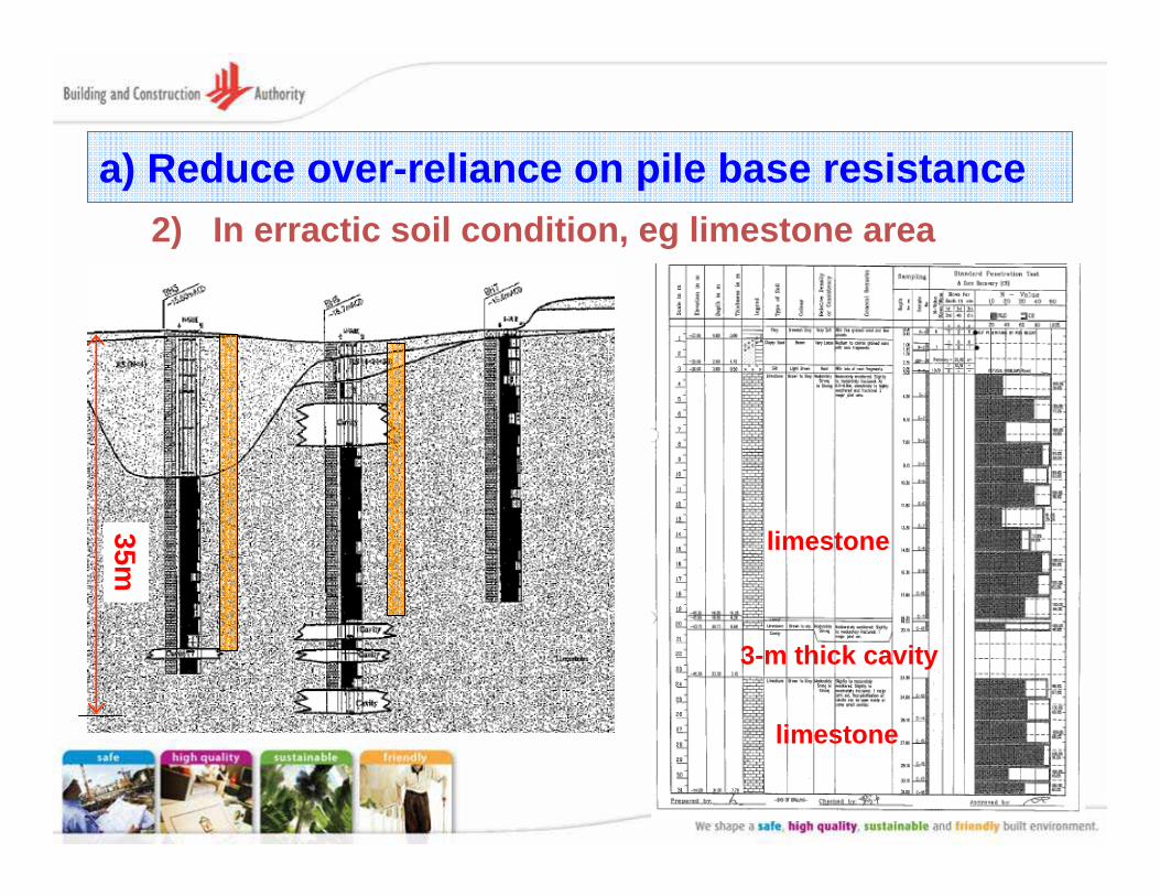
a) Reduce over-reliance on pile base resistance2) In erractic soil condition, eg limestone area
35m
3-m thick cavity
limestone
limestone
64
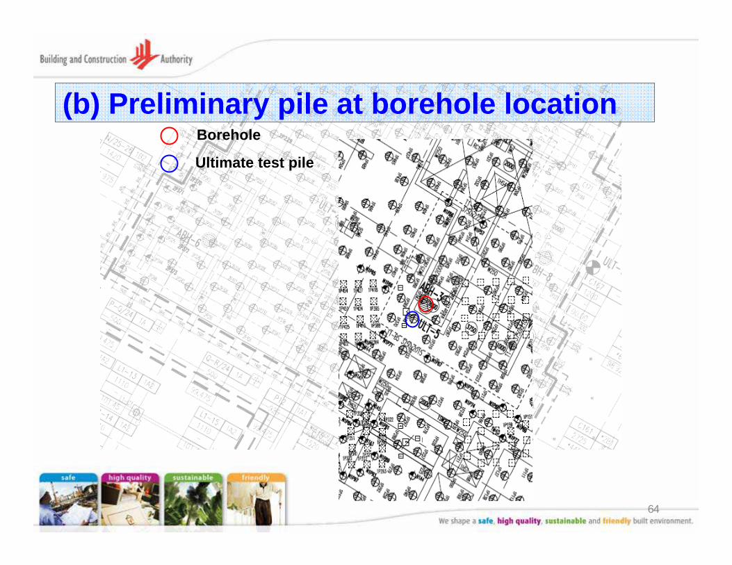
(b) Preliminary pile at borehole locationBorehole
Ultimate test pile
65
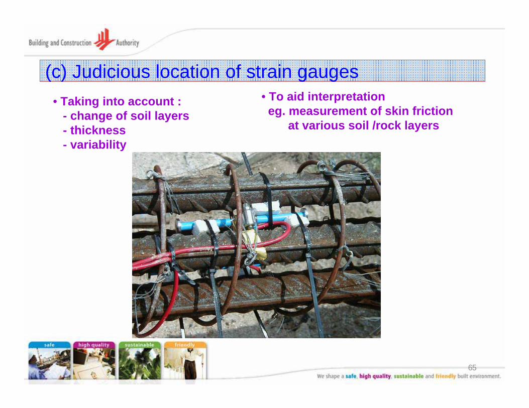
(c) Judicious location of strain gauges• Taking into account :
- change of soil layers- thickness- variability
• To aid interpretationeg. measurement of skin friction
at various soil /rock layers
66
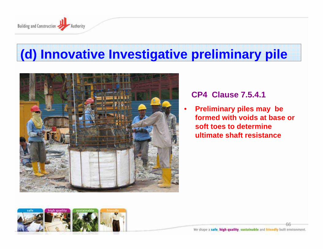
(d) Innovative Investigative preliminary pile
• Preliminary piles may be formed with voids at base or soft toes to determine ultimate shaft resistance
CP4 Clause 7.5.4.1
67
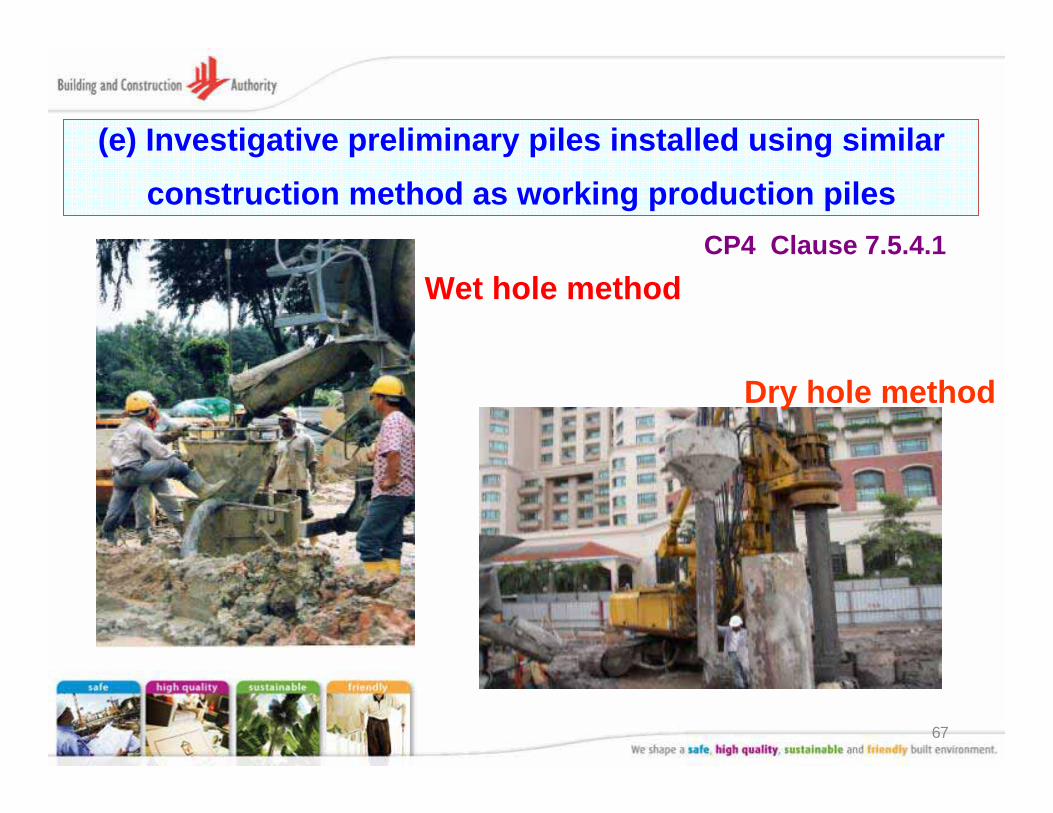
(e) Investigative preliminary piles installed using similar construction method as working production piles
Dry hole method
Wet hole methodCP4 Clause 7.5.4.1

68
(f) Proper transfer of load to Kentledge frame
Use stiffener for effective transfer
69
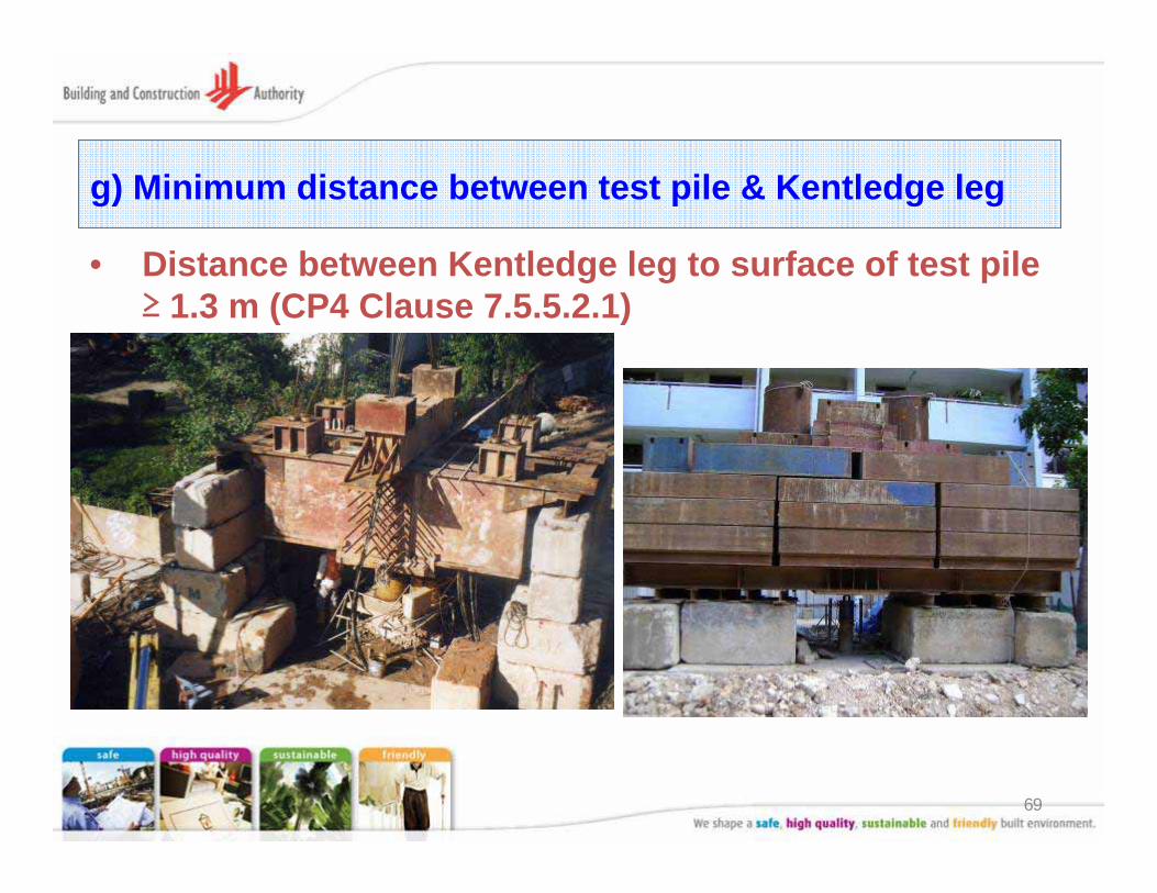
g) Minimum distance between test pile & Kentledge leg
• Distance between Kentledge leg to surface of test pile ≥ 1.3 m (CP4 Clause 7.5.5.2.1)
70
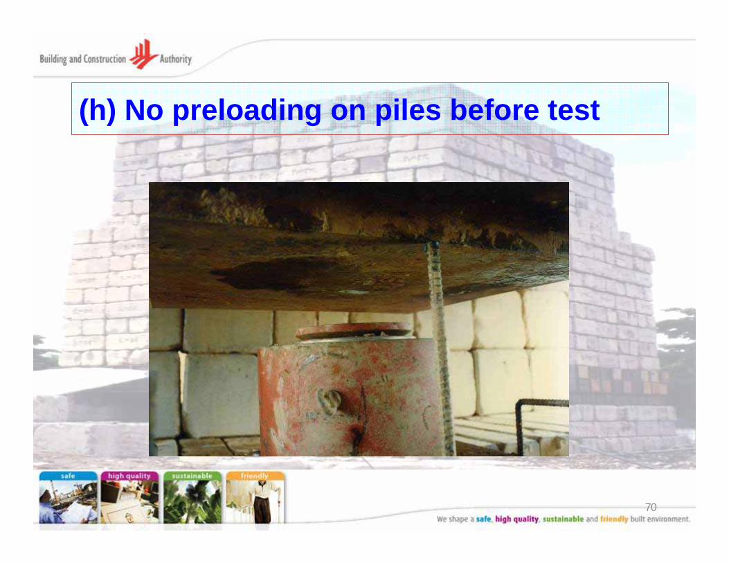
(h) No preloading on piles before test
71
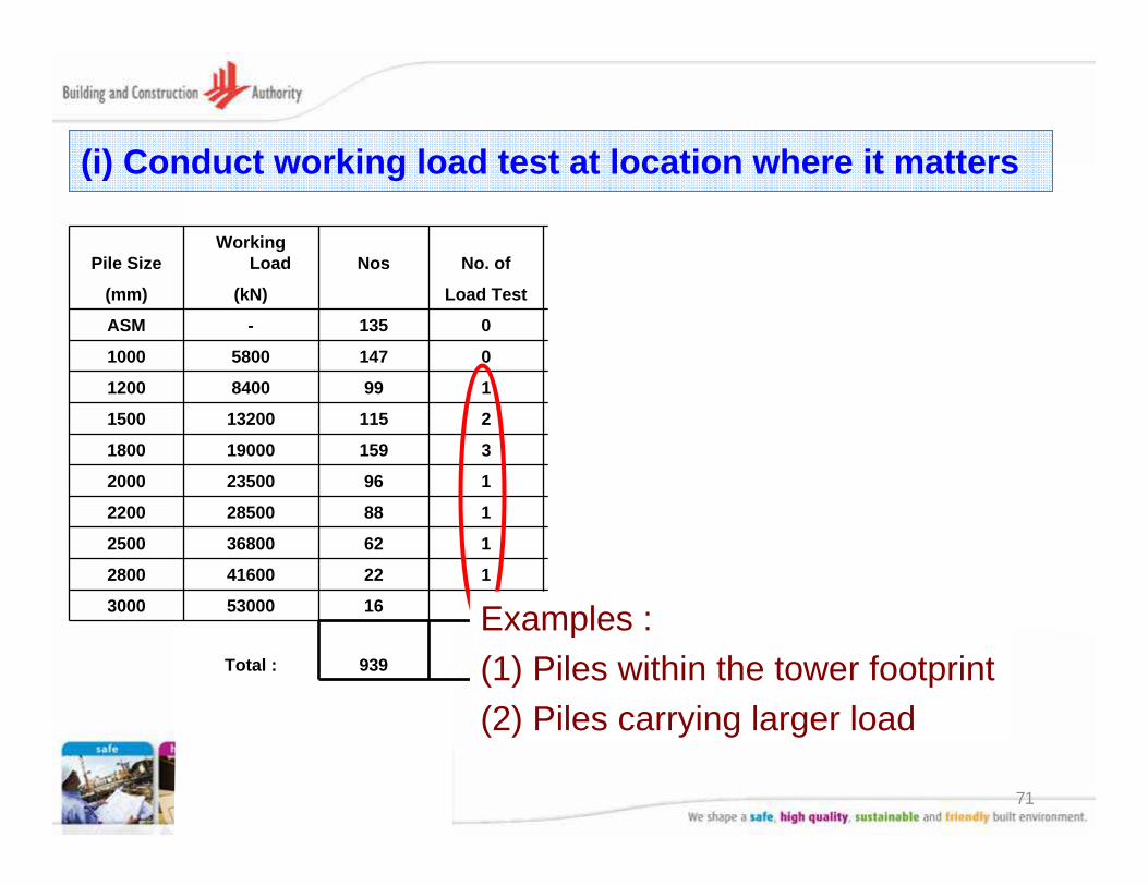
Pile SizeWorking
Load Nos No. of Method of
(mm) (kN) Load Test Test
ASM - 135 0 -
1000 5800 147 0 -
1200 8400 99 1 Kentledge
1500 13200 115 2 Kentledge
1800 19000 159 3 Bi-Directional
2000 23500 96 1 Bi-Directional
2200 28500 88 1 Bi-Directional
2500 36800 62 1 Bi-Directional
2800 41600 22 1 Bi-Directional
3000 53000 16 0 -
Total : 939 10
(i) Conduct working load test at location where it matters
Examples : (1) Piles within the tower footprint(2) Piles carrying larger load
72
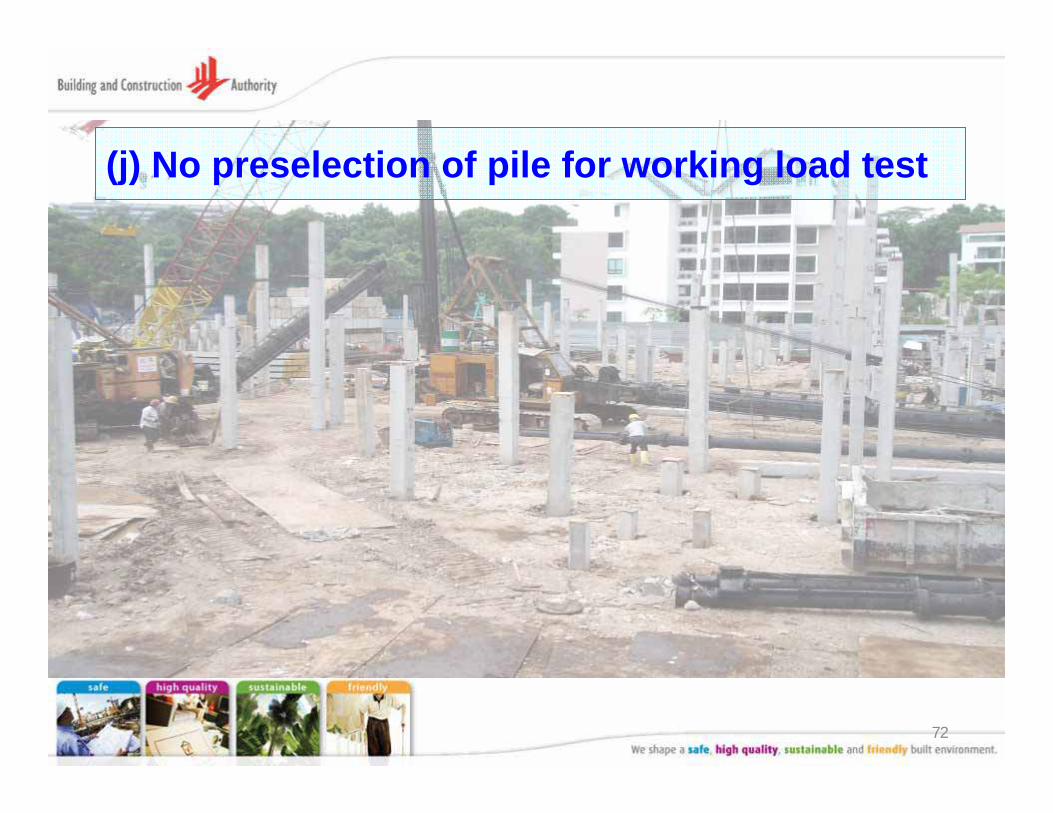
(j) No preselection of pile for working load test
73
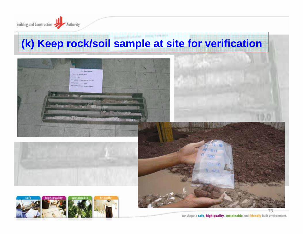
(k) Keep rock/soil sample at site for verification
74
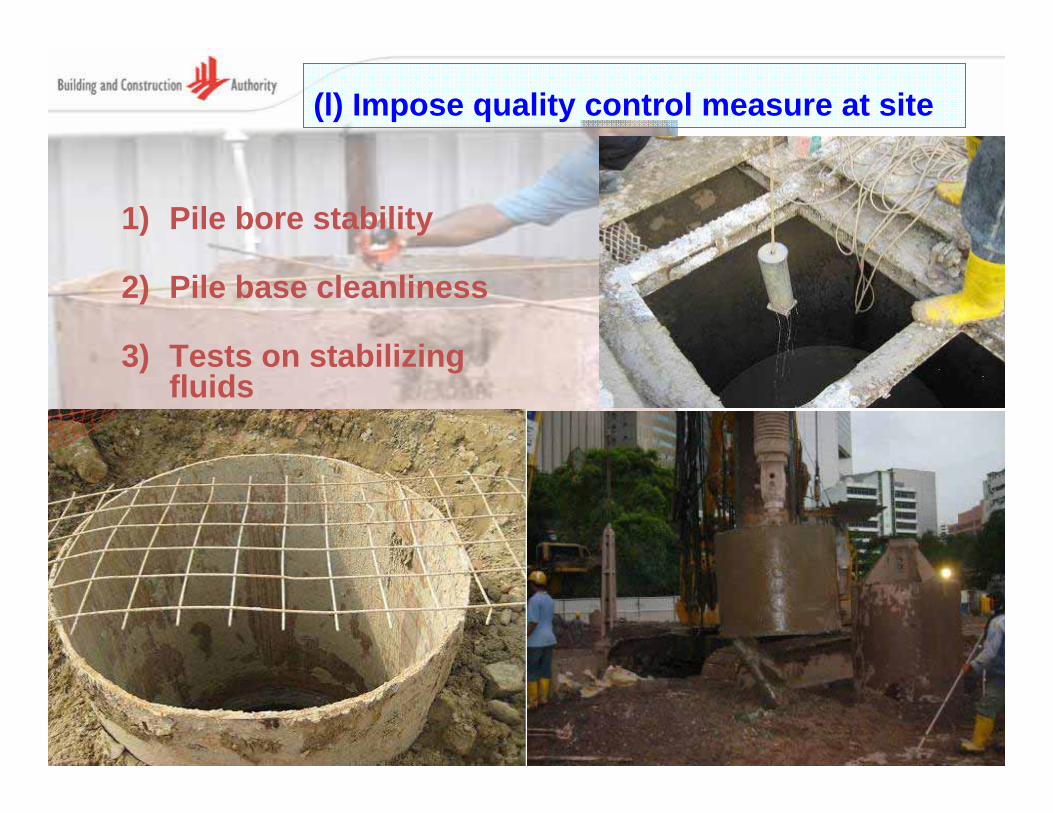
(l) Impose quality control measure at site
1) Pile bore stability
2) Pile base cleanliness
3) Tests on stabilizing fluids
75
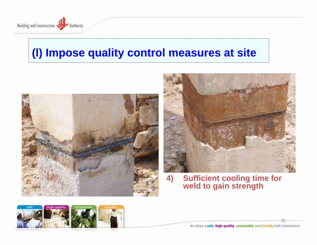
(l) Impose quality control measures at site
4) Sufficient cooling time for weld to gain strength
76
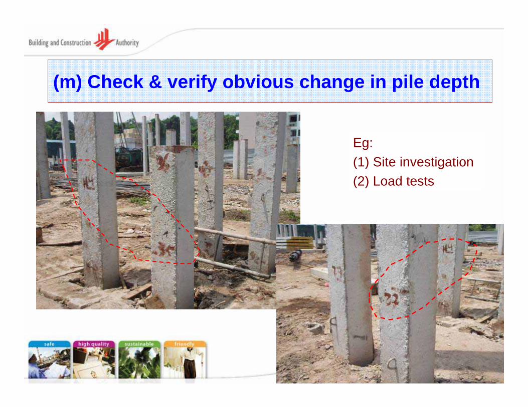
(m) Check & verify obvious change in pile depth
Eg: (1) Site investigation(2) Load tests
77
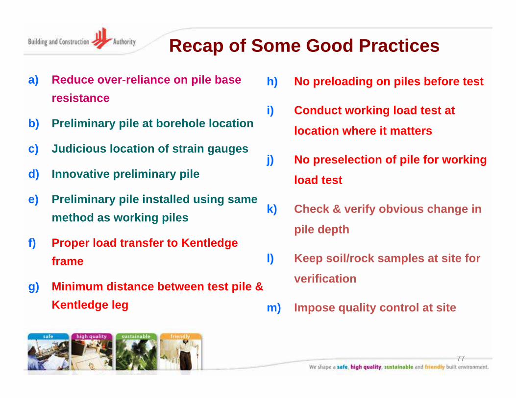
Recap of Some Good Practices
a) Reduce over-reliance on pile base resistance
b) Preliminary pile at borehole location
c) Judicious location of strain gauges
d) Innovative preliminary pile
e) Preliminary pile installed using same method as working piles
f) Proper load transfer to Kentledgeframe
g) Minimum distance between test pile & Kentledge leg
h) No preloading on piles before test
i) Conduct working load test at
location where it matters
j) No preselection of pile for working
load test
k) Check & verify obvious change in
pile depth
l) Keep soil/rock samples at site for
verification
m) Impose quality control at site
78
Summary
1. Requirements of piling plan submission under recent BC amendment Act and Regulations
2. Requirements for foundations of buildings more than 10-storeys
3. Good practices in design, load tests & construction
79
Concluding remark
• QP who prepare plans and calculations for piling plans have to comply with the requirements of BC Act and regulations
Standard Certification by QP on plans and calculations“I .... certify that they have been prepared in accordance with the provisions of the Building Control Regulations, the Building Control Act and any other written law pertaining to buildings and construction for the time being in force.”

80
Thank you !
THE END