2G HTS Properties Beyond Critical Current
28
superior performance. powerful technology. SuperPower Inc. is a subsidiary of Furukawa Electric Co. Ltd. 2G HTS Properties Beyond Critical Current DW Hazelton Friday, October 11, 2013 CHATS 2013, Cambridge MA
Transcript of 2G HTS Properties Beyond Critical Current

superior performance. powerful technology.
SuperPower Inc. is a subsidiary of Furukawa Electric Co. Ltd.
2G HTS Properties Beyond Critical Current
DW HazeltonFriday, October 11, 2013 CHATS 2013, Cambridge MA
CHATS 2013 Cambridge, MA October 11, 2013All Rights Reserved. Copyright SuperPower® Inc. 2013
Acknowledgements
2
• We would like to acknowledge the contributions of the team at SuperPower as well as collaborators from around the world.
• In particular we would like to acknowledge the input from Toru Fukushima, Paul Brownsey, Honghai Song*, Yifei Zhang, Justin Waterman, Trudy Lehner, Hisaki Sakamoto, John Dackow, Ross McClure and Allan Knoll.
• The work presented here is supported in part from funding from the US DOE Smart Grid Program and ARPA-E.
*currently at MSU-FRIB

CHATS 2013 Cambridge, MA October 11, 2013All Rights Reserved. Copyright SuperPower® Inc. 2013
Outline
• SuperPower 2G HTS conductor architecture• Critical current status• Mechanical properties
– General properties– Delamination
• FCL functionality• Insulation• Splices• Closing remarks
3

CHATS 2013 Cambridge, MA October 11, 2013All Rights Reserved. Copyright SuperPower® Inc. 2013 4
Wire performance critical to practical applications• Ic(B, T, )
– Temperature, magnetic field and field orientation dependence of Ic– Minimum Ic at operating condition
• Mechanical properties (electromechanical performance)– Workability for fabrication into various devices– Irreversible stress or strain limits under various stress condition, in terms
of Ic• Uniformity along length (Ic and other attributes)• Thermal properties (thermal expansion coefficient and thermal conductivity)• Quench stability (NZPV and MQE)• Insulation (material and method)• Splice
– Resistance (resistivity)– Mechanical strength (tensile and bending)
CHATS 2013 Cambridge, MA October 11, 2013All Rights Reserved. Copyright SuperPower® Inc. 2013
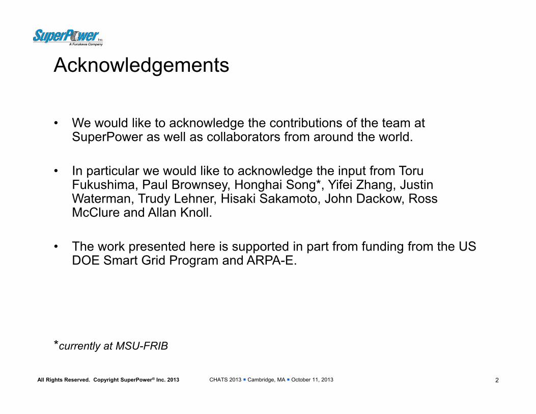
• Hastelloy® C276 substrate• high strength• high resistance• non-magnetic
• Buffer layers with IBAD-MgO • Diffusion barrier to metal substrate• Ideal lattice matching from substrate through ReBCO
• MOCVD grown ReBCO layer with BZO nanorods• Flux pinning sites for high in-field Ic
• Silver and copper stabilization
SuperPower’s ReBCO superconductor with artificial pinning structure provides a solution for demanding applications
5
CHATS 2013 Cambridge, MA October 11, 2013All Rights Reserved. Copyright SuperPower® Inc. 2013
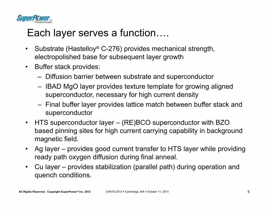
Each layer serves a function….• Substrate (Hastelloy® C-276) provides mechanical strength,
electropolished base for subsequent layer growth• Buffer stack provides:
– Diffusion barrier between substrate and superconductor– IBAD MgO layer provides texture template for growing aligned
superconductor, necessary for high current density– Final buffer layer provides lattice match between buffer stack and
superconductor• HTS superconductor layer – (RE)BCO superconductor with BZO
based pinning sites for high current carrying capability in background magnetic field.
• Ag layer – provides good current transfer to HTS layer while providing ready path oxygen diffusion during final anneal.
• Cu layer – provides stabilization (parallel path) during operation and quench conditions.
6

CHATS 2013 Cambridge, MA October 11, 2013All Rights Reserved. Copyright SuperPower® Inc. 2013
Ic(B,T, Φ) characterization is critical to understanding the impacts of processing on operational performance
7
Measurements made at the University of Houston
• Lift factor, Ic(B,T)/Ic(sf, 77K), particularly a full matrix of Ic(B,T, Φ) is in high demand.• Frequently sought by coil/magnet design engineer, for various applications.• Used to calculate local Iop/Ic ratio inside coil body, and design quench protection.
0
1
2
3
4
5
6
7
0.0 2.0 4.0 6.0 8.0 10.0
Lift Factor [ Ic(H,T)/Ic(sf, T) ] //ab
Applied Field (Tesla)
M3‐909‐3 Lift Factor vs. H//ab, T65 K 50K 40 K 30K 20K
0
1
2
3
4
5
6
7
0.0 2.0 4.0 6.0 8.0 10.0
Lift Factor [ Ic(H,T)/Ic(sf, T) ] //ab
Applied Field (Tesla)
M3‐909‐3 Lift Factor vs. H//c, T65 K 50K 40 K 30K 20K
CHATS 2013 Cambridge, MA October 11, 2013All Rights Reserved. Copyright SuperPower® Inc. 2013
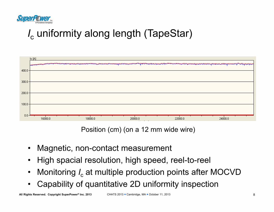
Ic uniformity along length (TapeStar)
8
Position (cm) (on a 12 mm wide wire)
• Magnetic, non-contact measurement• High spacial resolution, high speed, reel-to-reel• Monitoring Ic at multiple production points after MOCVD• Capability of quantitative 2D uniformity inspection

CHATS 2013 Cambridge, MA October 11, 2013All Rights Reserved. Copyright SuperPower® Inc. 2013
Ic uniformity along length (four-probe transport measurement)
9
Position (m) (on a 4 mm wide wire)
Ic (A
, 77K
, s.f.
) and
n-v
alue

CHATS 2013 Cambridge, MA October 11, 2013All Rights Reserved. Copyright SuperPower® Inc. 2013
Tensile strength predominately determined by substrate
10
Tensile stress-strain relationship of SCS4050 wires with different Cu stabilizer thickness (room temperature)
Tensile stress-strain relationship of as-polished Hastelloy substrate(room temperature)
100 µm Cu
40 µm Cu
20 µm Cu

CHATS 2013 Cambridge, MA October 11, 2013All Rights Reserved. Copyright SuperPower® Inc. 2013
0
200
400
600
800
1000
1200
0.000 0.002 0.004 0.006 0.008 0.010 0.012
stress (M
Pa)
strain
Copper thickness
40 µm
60 µm
100 µm
Conductor Stress‐Strain at 77K and 4 K with Various Copper Thickness
Significant softening of the stress‐strain curve with added copper due to reduced modulus and yielding of the copper.

CHATS 2013 Cambridge, MA October 11, 2013All Rights Reserved. Copyright SuperPower® Inc. 2013
Tensile strength - effect of stress on Ic
12
Normalized Ic vs. room temperature tensile stress for a 12mm wide wire with 100m Cu stabilizer

CHATS 2013 Cambridge, MA October 11, 2013All Rights Reserved. Copyright SuperPower® Inc. 2013
Tensile test of wires with SCS
13
• Measurement of baseline data• Effect of Cu/Hastelloy ratio
M3-914-1 (100µm Cu)Stress limit 460MPa
M3-861-2 (40µm Cu)Stress limit 620MPa
CHATS 2013 Cambridge, MA October 11, 2013All Rights Reserved. Copyright SuperPower® Inc. 2013
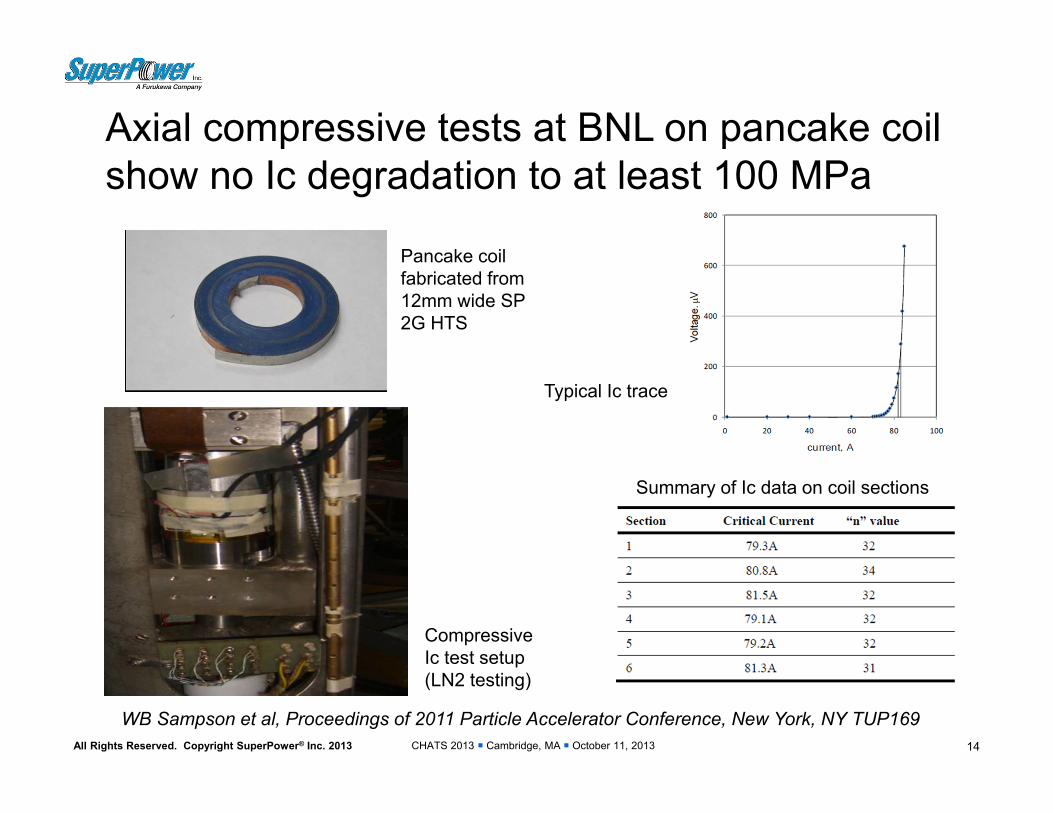
Axial compressive tests at BNL on pancake coil show no Ic degradation to at least 100 MPa
14
WB Sampson et al, Proceedings of 2011 Particle Accelerator Conference, New York, NY TUP169
Pancake coil fabricated from 12mm wide SP 2G HTS
Compressive Ic test setup (LN2 testing)
Typical Ic trace
Summary of Ic data on coil sections

CHATS 2013 Cambridge, MA October 11, 2013All Rights Reserved. Copyright SuperPower® Inc. 2013
(RE)BCO coils can be subject to degradation under thermal cycling
15
Conclusions(1) The critical current of epoxy impregnated
circular coils wound using YBCO-coated conductors can be degraded in use.
(2) Degradation occurs if the cumulative radial stress developed due to winding, cool down and Lorentz force exceeds the critical transverse stress for the YBCO coated conductor, typically +10 MPa.
(3) The YBCO conductor is fractured at the interface between the buffer layer and the YBCO layer, or at the YBCO layer itself, causing cracks on the YBCO layer resulting in significant decline of the critical current.
• Takematsu et al., Physica C 674-677, 470, 2011

CHATS 2013 Cambridge, MA October 11, 2013All Rights Reserved. Copyright SuperPower® Inc. 2013
Cu
REBCOBuffer
Hastelloy
Cu
Cohesive
Adhesive
Mixed mode
Ag
Ag
Delamination strength studied with peel test
16
P
T-peel test
90 peel test
P
Displacement (mm)
Pee
ling
Load
(N)
Relationship between peel strength and processing conditions established

CHATS 2013 Cambridge, MA October 11, 2013All Rights Reserved. Copyright SuperPower® Inc. 2013
Successful winding techniques demonstrated to mitigate delamination issue • Decoupling of former from winding has been demonstrated to be
beneficial– Eliminates radial tensile stress on the 2G HTS windings– PET release layer incorporated at former:windings interface– Lower thermal expansion formers (Ti, controlled expansion glass-
epoxy)• Alternative insulations/epoxy systems have been successfully
demonstrated– PET shrink tube - NHMFL– Electrodeposited polyimide - Riken– Alternative epoxy system with filler - KIT
• Use of cowound stainless steel as “insulation” with partial epoxy application on coil sides – Mitigates radial tensile stress on the 2G HTS – Improves overall coil strength– Negative impact on coil current density
17

CHATS 2013 Cambridge, MA October 11, 2013All Rights Reserved. Copyright SuperPower® Inc. 2013
Stainless steel insulation, partial epoxy application on coil sides shows resistance to delamination
18
• Very thin layer of epoxy (transparent) after epoxy is cured
• Mechanical fix turn-turn and layer-layer
• Provides thermal link between optional cooling plates and windings
• Seals the coil
-2.00E-03
0.00E+00
2.00E-03
4.00E-03
6.00E-03
8.00E-03
1.00E-02
0 10 20 30 40 50
Vol
tage
(V)
Current (A)
TC#1
TC#2
TC#3
TC#4
TC#5
Five thermal cycles (77K), no degradation found

CHATS 2013 Cambridge, MA October 11, 2013All Rights Reserved. Copyright SuperPower® Inc. 2013
0.0E+00
2.0E‐04
4.0E‐04
6.0E‐04
8.0E‐04
1.0E‐03
1.2E‐03
1.4E‐03
0 10 20 30 40 50
Volta
ge over 1
0 meter (V
)
Current (A)
TC#5 TC#4 TC#3 TC#2 TC#1
Alternative epoxy for wet wound coils shows resistance to delamination
• Design of experiments on Adraldite™ epoxy with Alumina– Epoxy (Araldite DBF): hardener (Araldite 951) = 10:1
• A fully wet wound coil– Conductor M3-919-2 BS, 566-576, 10 meter, 52 turns, ID=2’’– No additional insulation except for the epoxy, PET release
• Five thermal cycle, no degradation found
19
Ic=42.9A, n-value=~18
Five thermal cycles, no degradation
‐1.5E‐03
‐1.0E‐03
‐5.0E‐04
0.0E+00
5.0E‐04
1.0E‐03
1.5E‐03
2.0E‐03
0 10 20 30 40 50Volta
ge (V
)
Current (A)
200 A/min 10 A/min
In TC#5, ramp rate comparison, no difference in Ic and n-value, 42.9A/17.5
[C Barth et al, KIT, SuST. 26 (2013) 055007]

CHATS 2013 Cambridge, MA October 11, 2013All Rights Reserved. Copyright SuperPower® Inc. 2013
-100
-80
-60
-40
-20
0
20
40
60
80
0 20 40 60 80 100
Time [ms]
Cur
rent
[kA
]
-2.0
-1.0
0.0
1.0
2.0
3.0
4.0
5.0
6.0
7.0
Volta
ge a
cros
s H
TS
elem
ents
[kV]
Iprospective I_total_KEMA I_HTS Ish V_total_KEMA
-5.0-4.0
-3.0-2.0-1.00.0
1.02.03.0
4.05.0
2 4 6 8 10 12 14 16 18 20
Time [ms]
Cur
rent
[kA
]
-1.0-0.5
0.00.51.01.5
2.02.53.0
3.54.0
Volta
ge a
cros
s H
TS
elem
ents
[kV]
I_total_KEMA I_HTS Ish V_total_KEMA
Quench speed around 0.5 ms
2G Conductor for SFCL Shows Consistent, Excellent Performance
High-power SFCL test 2G
Prospective current 90 kA*
Limited current 32 kA
Peak current through element
3 kA
Response time < 1 ms
Element quality range Uniform
Fast response time

CHATS 2013 Cambridge, MA October 11, 2013All Rights Reserved. Copyright SuperPower® Inc. 2013
Capability for bonded conductors being developed [higher amperage, specialty applications (FCL) ]
21
• Bonded conductors offer the ability to achieve higher operating currents– LV windings of FCL transformer– HEP applications– High current bus applications
• Bonded conductors offer higher strength – FCL transformer fault currents– High field HEP applications with high force loadings
• Bonded conductors offer the ability to tailor application specific operating requirements, i.e. normal state resistance for a FCL transformer

CHATS 2013 Cambridge, MA October 11, 2013All Rights Reserved. Copyright SuperPower® Inc. 2013 22
0.000
0.020
0.040
0.060
0.080
0.100
0.120
0.140
0 100 200 300 400 500
resi
stan
ce /
leng
th (o
hm /
m)
temperature (K)
composite resistance / length 70Cu-30Ni
0.100 mm 0.200 mm 0.300 mm0.400 mm 0.500 mm 0.600 mm0.800 mm 1.000 mm target
12 mm wideC276 50.0 m(RE)BCO 1.0 msilver alloy 4.0 msolder 10.0 m
target
Bonded conductors meet target normal state resistance while meeting mechanical strength targets for FCL transformer application]
• DOE SMART GRID Project• 28 MVA 3-phase FCL Medium
Power Utility Transformer (69 kV / 12.47 kV class)
• Testing on So. California Edison Smart Grid site in Irvine, CA – plan min 1 year of grid operation

CHATS 2013 Cambridge, MA October 11, 2013All Rights Reserved. Copyright SuperPower® Inc. 2013
Insulation and other ongoing developments
• Additional wire insulation methods under development– Today: Kapton®/Polyimide wrapped (1-2 kV)– Other options under development:
thinner profile, better coverage
• Additional wire architectures under development – Higher current carrying capability
• Multi-layer combinations• Cable on Round Core (CORC)• Thinner substrates
– Custom attributes• FCL – normal state resistance feature
23
Courtesy: Advanced Conductor Technologies
CHATS 2013 Cambridge, MA October 11, 2013All Rights Reserved. Copyright SuperPower® Inc. 2013
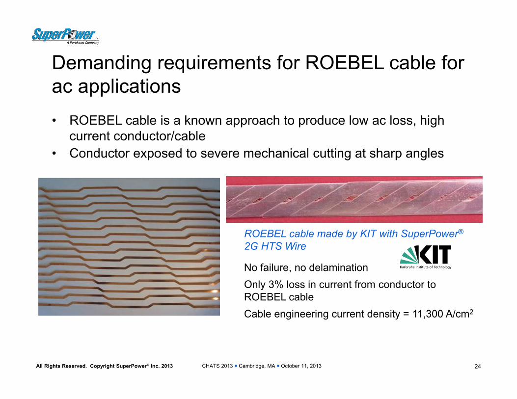
Demanding requirements for ROEBEL cable for ac applications• ROEBEL cable is a known approach to produce low ac loss, high
current conductor/cable• Conductor exposed to severe mechanical cutting at sharp angles
24
ROEBEL cable made by KIT with SuperPower®
2G HTS Wire
No failure, no delaminationOnly 3% loss in current from conductor to ROEBEL cableCable engineering current density = 11,300 A/cm2

CHATS 2013 Cambridge, MA October 11, 2013All Rights Reserved. Copyright SuperPower® Inc. 2013
Terminal leads, joint, transition
25
• Terminals and leads are potential sources of damage in 2G HTS coils• So their design, handling and fabrication are very critical• Key points: Avoid kinking or over bending, making smooth transition with adequate
support
Cu base for terminals and joints (FLAT leading in and out)
Bridge joints between pancakes, Rtot=10-7Ω
Smooth transition on inner crossover

CHATS 2013 Cambridge, MA October 11, 2013All Rights Reserved. Copyright SuperPower® Inc. 2013
Reliable splices – low resistance and high strength
26
• Splicing / terminations required in most applications
• Splice properties are important conductor performance and have influences on dielectrics and cryogenics as well
• Low resistance and high electromechanical strength are basic requirements
• Contact resistivity at REBCO/Ag interface has an effect on splice resistance• Splices fabricated via soldering at a temperature below 250C• Soldering temperature, pressure, duration time are important parameters• Ic retained across splices with no degradation through soldering• Splice resistance R ≤ 20 n for the lap joint geometry with a 10cm overlap
length
Bridge joints between pancakes, Rtot = 10-7Ω

CHATS 2013 Cambridge, MA October 11, 2013All Rights Reserved. Copyright SuperPower® Inc. 2013 27
Splice Ic and resistance vs. bending diameter
Bending Diameter (mm)
I c(d
) / I c
(∞) o
r R(d
) / R
(∞) R
atio
• Lap joint (HTS-HTS) of SCS4050 tapes with 40 µm Cu stabilizer• R(∞) = 6 ~ 20 n with 10 cm overlap length• Bent at room temperature and Ic measured at 77K
CHATS 2013 Cambridge, MA October 11, 2013All Rights Reserved. Copyright SuperPower® Inc. 2013
Closing remarks
• SuperPower 2G HTS conductor offers a flexible architecture to address the broad range of demanding applications requirements
• SuperPower is engaging major resources in improving its manufacturing capabilities to deliver a consistent, reliable, high quality 2G HTS product– Improved mechanical properties– Improved piece length / uniformity– Improved current density– Improved splice resistance
• Alternative conductor configurations are being developed to address customer specific requirements– Ag alloy– Bonded conductors
28