2G HTS Applications Developments - SuperPower IncSC+Devices+for+Wind+Energy_Barcelona.pdf ·...
62
superior performance. powerful technology. SuperPower, Inc. is a subsidiary of Royal Philips Electronics N.V. 2G HTS Applications Developments Drew W. Hazelton Principal Engineer, SuperPower Inc. Symposium on Superconducting Devices for Wind Energy Barcelona, Spain – 25 February 2011
Transcript of 2G HTS Applications Developments - SuperPower IncSC+Devices+for+Wind+Energy_Barcelona.pdf ·...

superior performance.powerful technology.
SuperPower, Inc. is a subsidiary of Royal Philips Electronics N.V.
2G HTS Applications DevelopmentsDrew W. HazeltonPrincipal Engineer, SuperPower Inc.
Symposium on Superconducting Devices for Wind EnergyBarcelona, Spain – 25 February 2011

1Symposium on SC Devices for Wind Energy, Barcelona 2/25/11
Outline
• 2G HTS for SC Applications
• Projects– 2G HTS SMES– FCL Transformer– FCL Module Development– HTS Cable– HTS Generator / Motor
• Summary

2Symposium on SC Devices for Wind Energy, Barcelona 2/25/11
SuperPower® 2G HTS wire architecture

3Symposium on SC Devices for Wind Energy, Barcelona 2/25/11
Advantages of SuperPower 2G HTS technology• Virtually any substrate can be used due to
IBAD texture layer– High-strength substrates– Non-magnetic substrates– Low cost, off-the shelf substrates (Inconel,
Hastelloy, Stainless Steel)– Very thin substrates (50 μm)– Resistive substrates – for low ac losses– Easy to handle – less possibility of defects
• Small grain size – sub-micron range– No issues with percolation in any length – Can pattern wire to very narrow filaments for low
ac loss wire• IBAD MgO develops excellent texture within 10 nm
thickness– High throughput
Assist Ion BeamIBSD
Source
Target
Substrate Block

4Symposium on SC Devices for Wind Energy, Barcelona 2/25/11
2G HTS offers excellent performance for all electrical device operating ranges
Normalized Ic vs. Applied Field //c
0.01
0.10
1.00
10.00
0.0 2.0 4.0 6.0 8.0 10.0 12.0 14.0 16.0Applied Field B (T)
Ic (B
//c, T
) / Ic
(sel
f fie
ld, 7
7 K
)
4.2 K 14 K 22 K 33 K 45 K 50 K 65 K 77 K
Cables, FCLs, transformers
Motors, generators
SMES

5Symposium on SC Devices for Wind Energy, Barcelona 2/25/11
Excellent performance extends to higher fields, enhanced with Zr-doping
Advances with Zr-doping being locked into production
SMES

6Symposium on SC Devices for Wind Energy, Barcelona 2/25/11
2G HTS Wire – Ic vs. Axial StressIc/Ic(0) Versus Stress at 77K
Tape ID # M3-383-1-BS504-569M
0.0
0.1
0.2
0.3
0.4
0.5
0.6
0.7
0.8
0.9
1.0
1.1
0 100 200 300 400 500 600 700 800 900 1000
Stress [MPa]
Ic/Ic
(0)
0048 @ Peak Stress0048 Unloaded0115 @ Peak Stress0115 Unloaded0163 @ Peak Stress0163 Unloaded
Recommended Stress Limit
• Ic drops by up to 10% reversiblyunder peak stress up to 700 MPa (about 0.6% strain)
• Above 700 MPa (0.6% strain) Ic degrades irreversibly
• N-value does not change with peak stress up to 700 MPa
• N-value degrades irreversibly coincident with irreversible Ic degradation
• Define σIcRL (εIcRL) = “Ic Reversiblity Limit” = Peak monotonic stress (strain) for >98% reversibility of Ic
• σIcRL (εIcRL) = 700 MPa (0.6%)Data from Ron Holtz, NRL

7Symposium on SC Devices for Wind Energy, Barcelona 2/25/11
Outline
• 2G HTS for SC Applications
• Projects– 2G HTS SMES– FCL Transformer– FCL Module Development– HTS Cable– HTS Generator
• Summary

8Symposium on SC Devices for Wind Energy, Barcelona 2/25/11
Superconductors: improving the generation and delivery of power
Superconducting Transformer

9Symposium on SC Devices for Wind Energy, Barcelona 2/25/11
New superconducting magnetic energy storage (SMES) project initiated• Energy stored in DC magnetic field (E ~ B2)• ARPA-E funded proof of concept project recently awarded ($5.2M/3yr)• Project Participants
– ABB (lead – power electronics / system integration)– Brookhaven National Laboratory (high field coil design / fabrication)– SuperPower (2G HTS / coil design support)– UHouston (enhanced 2G HTS fabrication)
• Storage capability (~2.5 MJ / 20 kwh)– 25 Tesla coil– Enhanced power electronics– >80% round trip efficiency

10Symposium on SC Devices for Wind Energy, Barcelona 2/25/11
SMES Usage• SMES is currently used for short duration (secs) energy storage for
improving power quality• In a utility situation, SMES could be used for either:
− diurnal storage (hours), charged from baseload power at night and meeting peak loads during the day
− medium term storage (minutes) to level out variations in renewable (solar, wind) generation
GRIDS SMES SYSTEMSMES Coil
MV Feeder
Power ConverterABB
MV SiC Devices
Brookhaven NL
2G HTS WireSuperPower
MV/LV
MV/LV
MV/LV
HV/MV
Wind Park
Solar Park
Transmission Line
LV Loads
GRIDS SMES SYSTEM
(University of Houston )
11Symposium on SC Devices for Wind Energy, Barcelona 2/25/11
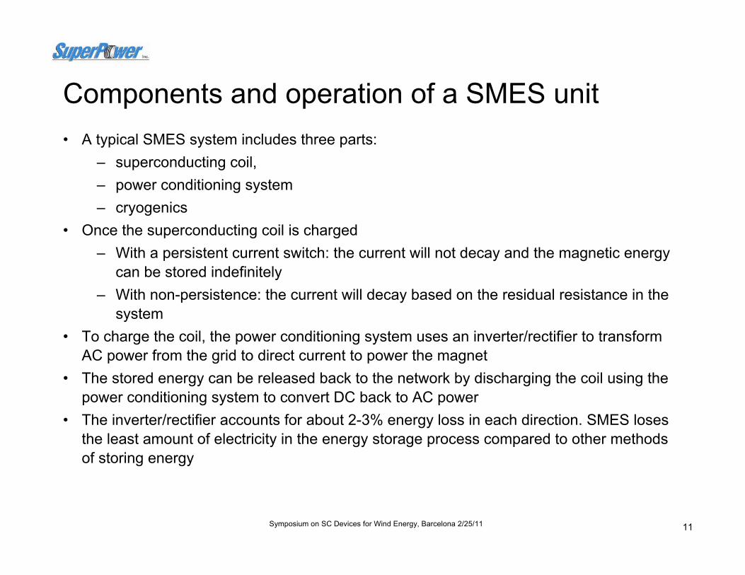
Components and operation of a SMES unit• A typical SMES system includes three parts:
– superconducting coil, – power conditioning system – cryogenics
• Once the superconducting coil is charged– With a persistent current switch: the current will not decay and the magnetic energy
can be stored indefinitely– With non-persistence: the current will decay based on the residual resistance in the
system• To charge the coil, the power conditioning system uses an inverter/rectifier to transform
AC power from the grid to direct current to power the magnet • The stored energy can be released back to the network by discharging the coil using the
power conditioning system to convert DC back to AC power • The inverter/rectifier accounts for about 2-3% energy loss in each direction. SMES loses
the least amount of electricity in the energy storage process compared to other methods of storing energy

12Symposium on SC Devices for Wind Energy, Barcelona 2/25/11
Why SMES?
• There are several reasons for using superconducting magnetic energy storage instead of other energy storage methods
– the time delay during charge and discharge is quite short – power is available almost instantaneously – very high power output can be provided for a brief period of time– high energy density
• Other energy storage methods, such as pumped hydro or compressedair have a substantial time delay associated with the energy conversionof stored mechanical energy back into electricity
• With SMES the loss of power is less than other storage methods• In SMES, the main parts are motionless, which results in high reliability

13Symposium on SC Devices for Wind Energy, Barcelona 2/25/11
Why high field HTS SMES?• Energy stored scales as B2 * r3, while losses scale as r2
• 2G HTS enables high field operation for a compact, high energy density system
• Toroidal geometry lessens the external magnetic forces, reducing the size of mechanical support needed
• Fields in a toroidal SMES are mainly axial (//a,b), maximizing the use of 2G HTS
• Due to the low external magnetic field, toroidal SMES can be located near a utility or customer load
14Symposium on SC Devices for Wind Energy, Barcelona 2/25/11
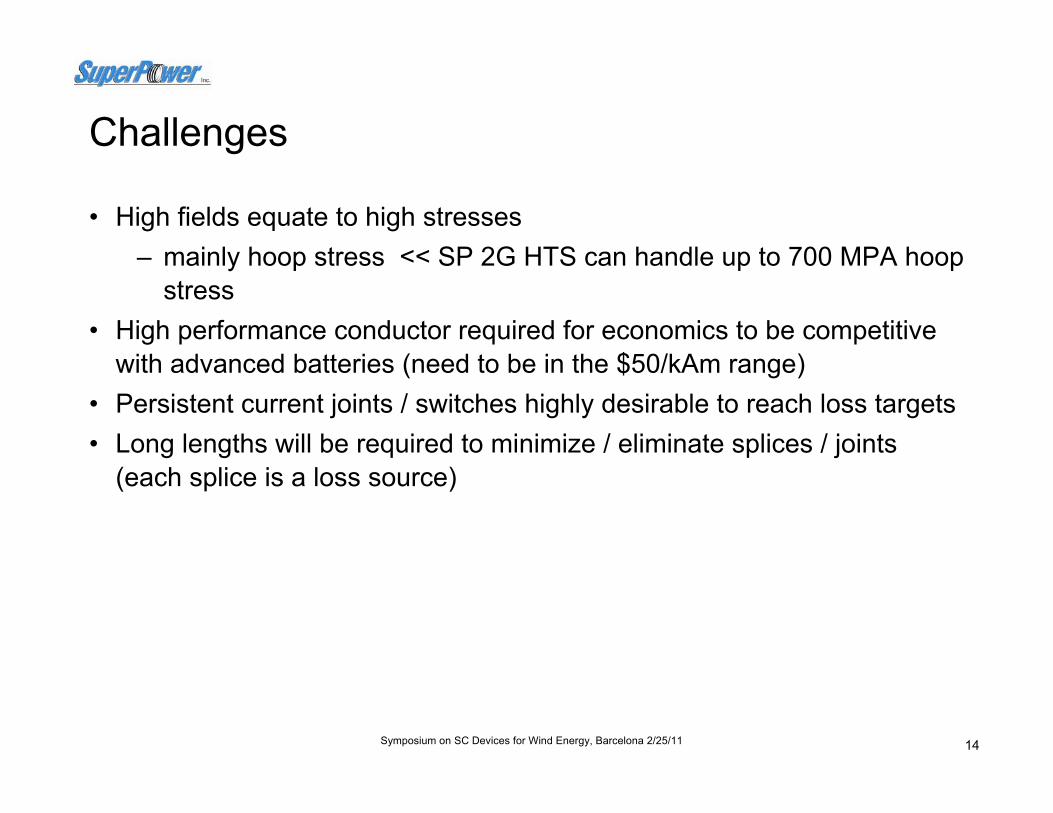
Challenges
• High fields equate to high stresses – mainly hoop stress << SP 2G HTS can handle up to 700 MPA hoop
stress• High performance conductor required for economics to be competitive
with advanced batteries (need to be in the $50/kAm range)• Persistent current joints / switches highly desirable to reach loss targets• Long lengths will be required to minimize / eliminate splices / joints
(each splice is a loss source)
15Symposium on SC Devices for Wind Energy, Barcelona 2/25/11
Outline
• 2G HTS for SC Applications
• Projects– 2G HTS SMES– FCL Transformer– FCL Module Development– HTS Cable– HTS Generator / Motor
• Summary

16Symposium on SC Devices for Wind Energy, Barcelona 2/25/11
HTS Transformers for the power grid – half the size and weightBenefits:• Greater efficiency• Smaller, lighter and quieter• Can run indefinitely above rated
power without affecting transformer life
• Do not require cooling oil like conventional transformers, thus eliminating the possibility of oil fires and related environmental hazards / costs
17Symposium on SC Devices for Wind Energy, Barcelona 2/25/11
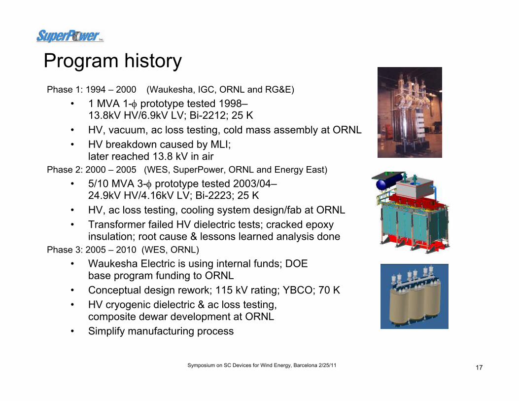
Program historyPhase 1: 1994 – 2000 (Waukesha, IGC, ORNL and RG&E)
• 1 MVA 1-φ prototype tested 1998–13.8kV HV/6.9kV LV; Bi-2212; 25 K
• HV, vacuum, ac loss testing, cold mass assembly at ORNL• HV breakdown caused by MLI;
later reached 13.8 kV in airPhase 2: 2000 – 2005 (WES, SuperPower, ORNL and Energy East)
• 5/10 MVA 3-φ prototype tested 2003/04–24.9kV HV/4.16kV LV; Bi-2223; 25 K
• HV, ac loss testing, cooling system design/fab at ORNL• Transformer failed HV dielectric tests; cracked epoxy
insulation; root cause & lessons learned analysis donePhase 3: 2005 – 2010 (WES, ORNL)
• Waukesha Electric is using internal funds; DOE base program funding to ORNL
• Conceptual design rework; 115 kV rating; YBCO; 70 K• HV cryogenic dielectric & ac loss testing,
composite dewar development at ORNL• Simplify manufacturing process

18Symposium on SC Devices for Wind Energy, Barcelona 2/25/11
Program historyPhase 4: 2010 - 2015 New Project • FCL transformer being designed and
constructed in a $ 21.2 M Smart Grid program
• Partners:– Waukesha Electric Systems, – SuperPower, – University of Houston, – Oak Ridge National Laboratory
• To be installed Southern California Edison grid by early 2014 (MacArthur Substation)
• 28 MVA (69 kV : 13 kV, 40 MVA overload capability)
• Fault current limiting capability ~ 40 to 50%

19Symposium on SC Devices for Wind Energy, Barcelona 2/25/11
Why HTS Transformers?
• HTS transformer development is underway worldwide– Projects in Japan, Korea, China, India, Australia
• The grid contains a great many transformers– On average there are 6-8 transformers between a generator and its load
• Many transformers in the grid are aging, creating a ready HTS market– 110,000 US transformers >10MVA are more than 35 years old
• HTS transformers can save energy and reduce CO2 emissions*– Even at 99.4% efficiency, transformer losses are 40% of total grid loss
because they are so numerous– If HTS transformer is 0.2% more efficient, losses are reduced by 1/3– SAVINGS– ~25 TW-hr, with associated 1.5 x 10⁷ ton annual CO2
reduction• Transformer size, weight, fire hazard, and environmental impact reduced.• Overload operation is possible with no loss of lifetime• Fault current limiting capability is possible– supports Smart Grid
20Symposium on SC Devices for Wind Energy, Barcelona 2/25/11
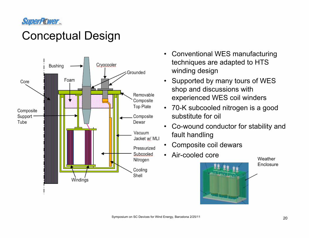
Conceptual Design• Conventional WES manufacturing
techniques are adapted to HTS winding design
• Supported by many tours of WES shop and discussions with experienced WES coil winders
• 70-K subcooled nitrogen is a good substitute for oil
• Co-wound conductor for stability and fault handling
• Composite coil dewars• Air-cooled core Weather
Enclosure
21Symposium on SC Devices for Wind Energy, Barcelona 2/25/11
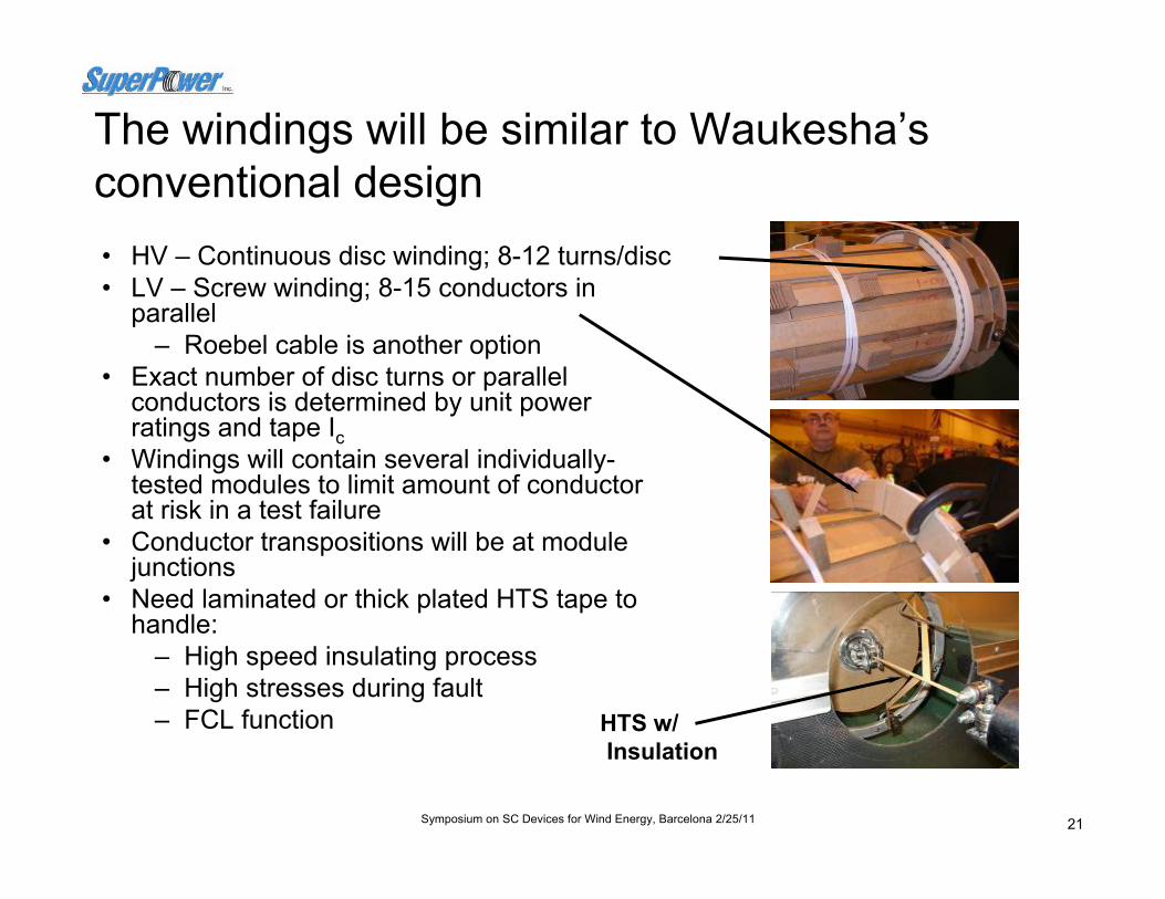
The windings will be similar to Waukesha’s conventional design• HV – Continuous disc winding; 8-12 turns/disc• LV – Screw winding; 8-15 conductors in
parallel– Roebel cable is another option
• Exact number of disc turns or parallel conductors is determined by unit power ratings and tape Ic
• Windings will contain several individually-tested modules to limit amount of conductor at risk in a test failure
• Conductor transpositions will be at module junctions
• Need laminated or thick plated HTS tape to handle:
– High speed insulating process– High stresses during fault– FCL function HTS w/
Insulation

22Symposium on SC Devices for Wind Energy, Barcelona 2/25/11
Insulation studies for up to 650 kV BIL successful
• Similar 350-kV BIL coil passed all tests in FY 2008
• Standard WES design pressboard structure
• Copper conductor with WES polymer insulation
• Disc windings• HV Tests in LN passed in Fall
2009
ECI Bushing Test
LVHVFlashover
• Electro-Composites 650 kV BIL bushing
• Solid epoxy core• Copper drawlead tube• ECI found no damage after
LN immersion• Production version on
order
Waukesha Test Coil

23Symposium on SC Devices for Wind Energy, Barcelona 2/25/11
Outline
• 2G HTS for SC Applications
• Projects– 2G HTS SMES– FCL Transformer– FCL Module Development– HTS Cable– HTS Generator / Motor
• Summary
24Symposium on SC Devices for Wind Energy, Barcelona 2/25/11
HTS Fault Current Limiters: New technology for a growing problem
• As new sources of generation are added, utilities are faced with the threat of higher levels of fault current
– HTS Fault Current Limiters (FCLs) address the market pull to cost-effectively correct fault current over-duty problems at the transmission voltage level of 138kV and higher
– The HTS FCLs will reduce the available fault current to a lower, safer level (20%-50% reduction), so that existing switchgear can still protect the grid
• Utility market needs at the transmission level:– Accommodate increasing fault currents due to added generation – Prevent breaker failures & associated problems (e.g., welded contacts, bus bracing,
etc.) – Maintain flexibility to accommodate load growth and “open access”– Avoid adverse side effects imposed by existing solutions– Reduce “through fault” stresses on aging infrastructure– Avoid need for expensive 80kA breaker upgrades
• HTS FCLs are a natural complement to AC HTS cable systems• Discussions with 20+ utilities have consistently validated the need
25Symposium on SC Devices for Wind Energy, Barcelona 2/25/11
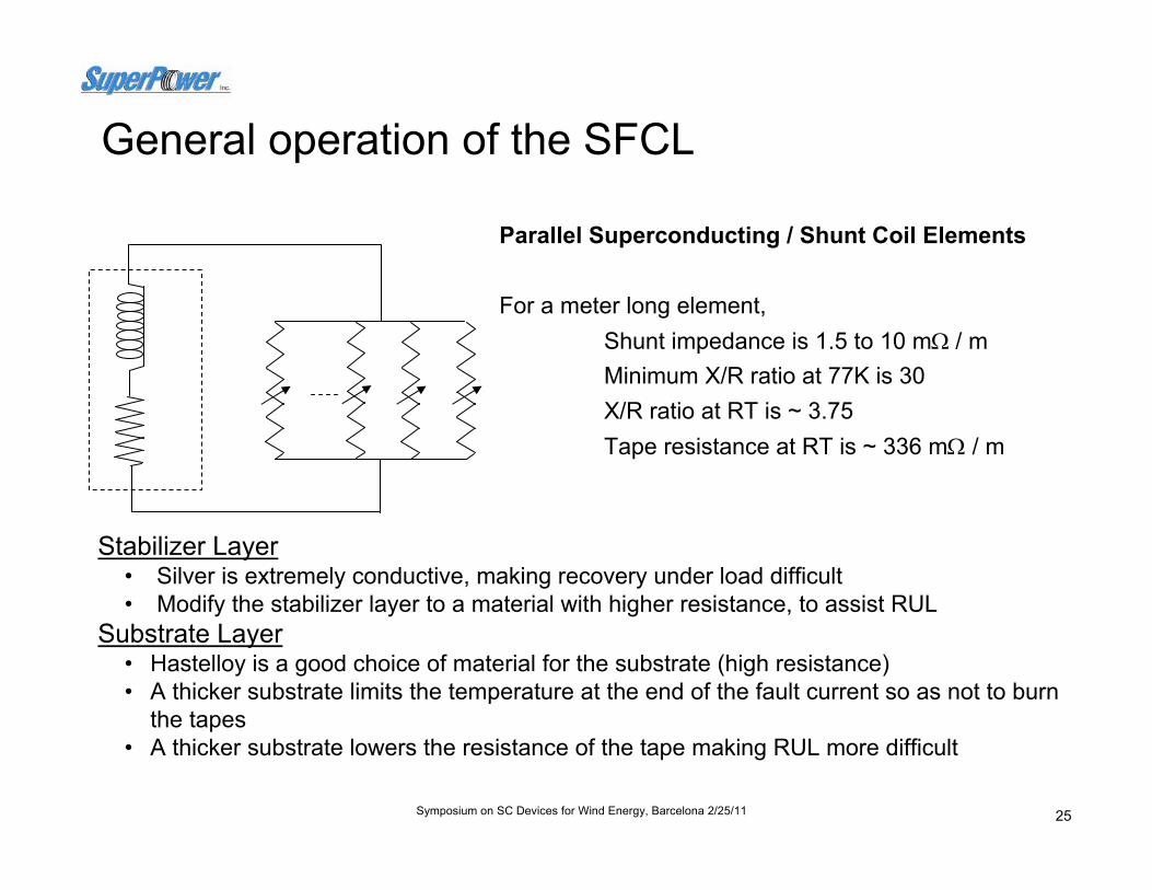
General operation of the SFCL
Parallel Superconducting / Shunt Coil Elements
For a meter long element, Shunt impedance is 1.5 to 10 mΩ / mMinimum X/R ratio at 77K is 30X/R ratio at RT is ~ 3.75Tape resistance at RT is ~ 336 mΩ / m
Stabilizer Layer• Silver is extremely conductive, making recovery under load difficult• Modify the stabilizer layer to a material with higher resistance, to assist RUL
Substrate Layer• Hastelloy is a good choice of material for the substrate (high resistance)• A thicker substrate limits the temperature at the end of the fault current so as not to burn
the tapes• A thicker substrate lowers the resistance of the tape making RUL more difficult

26Symposium on SC Devices for Wind Energy, Barcelona 2/25/11
Proof-of-concepts and developments through 2009• Fault Current Testing with MCP 2212 (2004)• Fault Current Testing with 2G YBCO (2006)• Completed design and testing of HV bushings (ORNL, SEI, 2006)• Weibull 2G failure study of ‘standard’ HTS superconductor architectures (2006)• Investigated several engineered 2G architectures for improved RUL (2008)• Improve connector design (2008)• Modify 2G conductor to improve performance for FCL application (2008)• Designed / tested compact 55kA shunt coils to withstand high fault transient loads (2008)• Thermal simulation of RUL process (2008)• Demonstrated Recovery Under Load (RUL) proof of concept and requirements (2008)• Investigated LN2 dielectric properties (with ORNL, 2005-2008)• Beta device testing specifications established (2008)• Study of the Impact of bubbles on breakdown mechanism and LN2 dielectric strength (with ORNL 2008)• Improved understanding of the impacts of recovery under load (RUL) for module design (2009)• Optimized performance of the 2G HTS wire (2009)• Investigated the performance of more compact ‘module’ concepts (2009)• Tested FCL module components at rated voltage in a cryogenic environment (2009)

27Symposium on SC Devices for Wind Energy, Barcelona 2/25/11
Reclosure sequence drives recovery requirements• Rounds of KEMA testing focused on critical AEP reclosure sequence on an HTS
element
• Straight and meander path elements were used• Improved connector designs were used
5 CyclesFault
13kA/7kA
18 Cycles Load Current
15 sec Load Current
135 sec Load Current
5 CyclesFault
13kA/7kA
5 CyclesFault
13kA/7kA
5 CyclesFault
13kA/7kA
Breaker opens and locks-out
Recovery under NO Load Current
5 CyclesFault
13kA/7kA
160 sec Load Current

28Symposium on SC Devices for Wind Energy, Barcelona 2/25/11
2G SFCL module development
• Matrix concept carried forward to allow for customization• No magnetic trigger coils with 2G – Ic trigger (possible due to tape
uniformity)• Non-inductive Design Concepts:
– Straight element design – concept with 40-50cm long elements of multiple parallel tapes, discrete joints to shunt coils – early design and testing, half length module (12 elements) tested at KEMA.
– Meander path design – similar to straight element design but without discrete joints, shunt coils tap into meander without 2Gbreak
• All designs look for robust construction with minimal number of joints

29Symposium on SC Devices for Wind Energy, Barcelona 2/25/11
Straight element design
Used in test module for KEMA test
− 12 elements (40 cm free) of 4 parallel tapes
− Discrete terminals at ends of elements
− One shunt coil (~10 mΩ) per pair of elements
− Mechanical terminations (no soldering) for 2G elements
• KEMA tests confirmed earlier single element (4 parallel tapes, 20 cm long) results.
Top view showing tape layout
End view showing shunt coils
Terminal detail

30Symposium on SC Devices for Wind Energy, Barcelona 2/25/11
-100
-80
-60
-40
-20
0
20
40
60
80
0 20 40 60 80 100
Time [ms]
Cur
rent
[kA
]
-2.0
-1.0
0.0
1.0
2.0
3.0
4.0
5.0
6.0
7.0
Volta
ge a
cros
s H
TS
elem
ents
[kV]
Iprospective I_total_KEMA I_HTS Ish V_total_KEMA
-5.0-4.0
-3.0-2.0-1.00.0
1.02.03.0
4.05.0
2 4 6 8 10 12 14 16 18 20
Time [ms]
Cur
rent
[kA
]
-1.0-0.5
0.00.51.01.5
2.02.53.0
3.54.0
Volta
ge a
cros
s H
TS
elem
ents
[kV]
I_total_KEMA I_HTS Ish V_total_KEMA
Quench speed around 0.5 ms
2G Conductor for SFCL shows consistent, excellent performance
< 1 msResponse time
3 kAPeak current through element
90 kA*Prospective current
32 kALimited current
NarrowElement quality range
2G High-power SFCL test
Fast response time

31Symposium on SC Devices for Wind Energy, Barcelona 2/25/11
KEMA test results – Energy in 2G FCL elements
Test Results –Energy dissipation • 2GFCL elements tested to
37.5 kA rms (100 kA peak) prospective fault current at 1200 V rms supply
• 2G tapes performed well up to 38 J/cm/tape and start failure at 43.91 J/cm/tape
• Design limit around 25 J/cm/tape – around 65% of failure value => need to establish probability of failure at variable energy level (Weibull distribution)
• Excellent current limiting performance
• Excellent agreement between simulation and test results – performance predictability is critical to success
2GFCL - 12 elements mockup test results at KEMA (Test # 4 to # 51), 137 V rms - 1200 V rms supply, 1.43 kA rms (3.81 kA peak) -
to - 37.5 kA rms (100 kA peak) prospective current
0
5
10
15
20
25
30
35
40
45
50
0 240 480 720 960 1200
Supply Voltage [V rms]
Ener
gy d
ensi
ty [J
/cm
/tape
]
Energy_HTS[J/cm/tape] (5kA setting)
Energy_HTS[J/cm/tape](10 kAsetting)
Energy_HTS[J/cm/tape](15 kAsetting)
Energy[J/cm/tape] -Simulated
Failure initiated
Target operating condition
32Symposium on SC Devices for Wind Energy, Barcelona 2/25/11
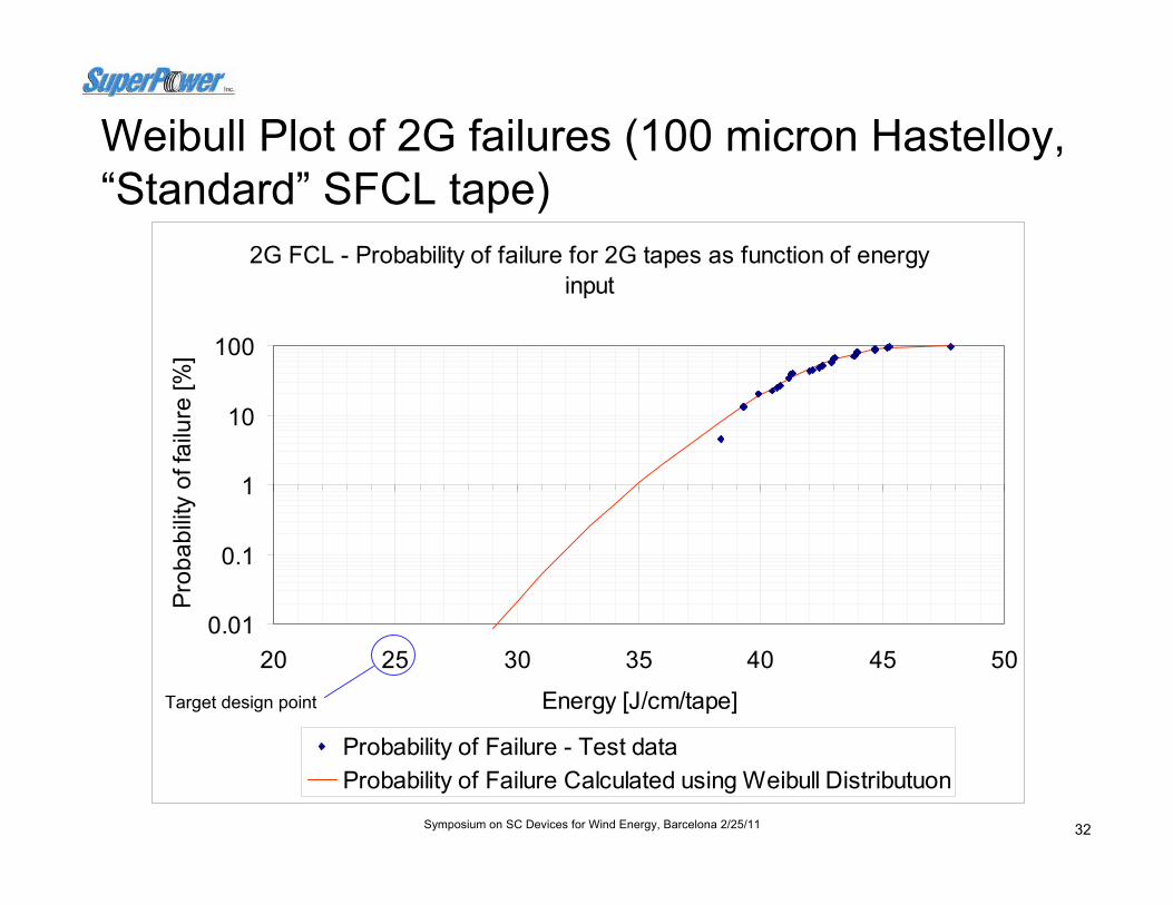
Weibull Plot of 2G failures (100 micron Hastelloy, “Standard” SFCL tape)
2G FCL - Probability of failure for 2G tapes as function of energy input
0.01
0.1
1
10
100
20 25 30 35 40 45 50
Energy [J/cm/tape]
Prob
abilit
y of
failu
re [%
]
Probability of Failure - Test dataProbability of Failure Calculated using Weibull Distributuon
Target design point
33Symposium on SC Devices for Wind Energy, Barcelona 2/25/11
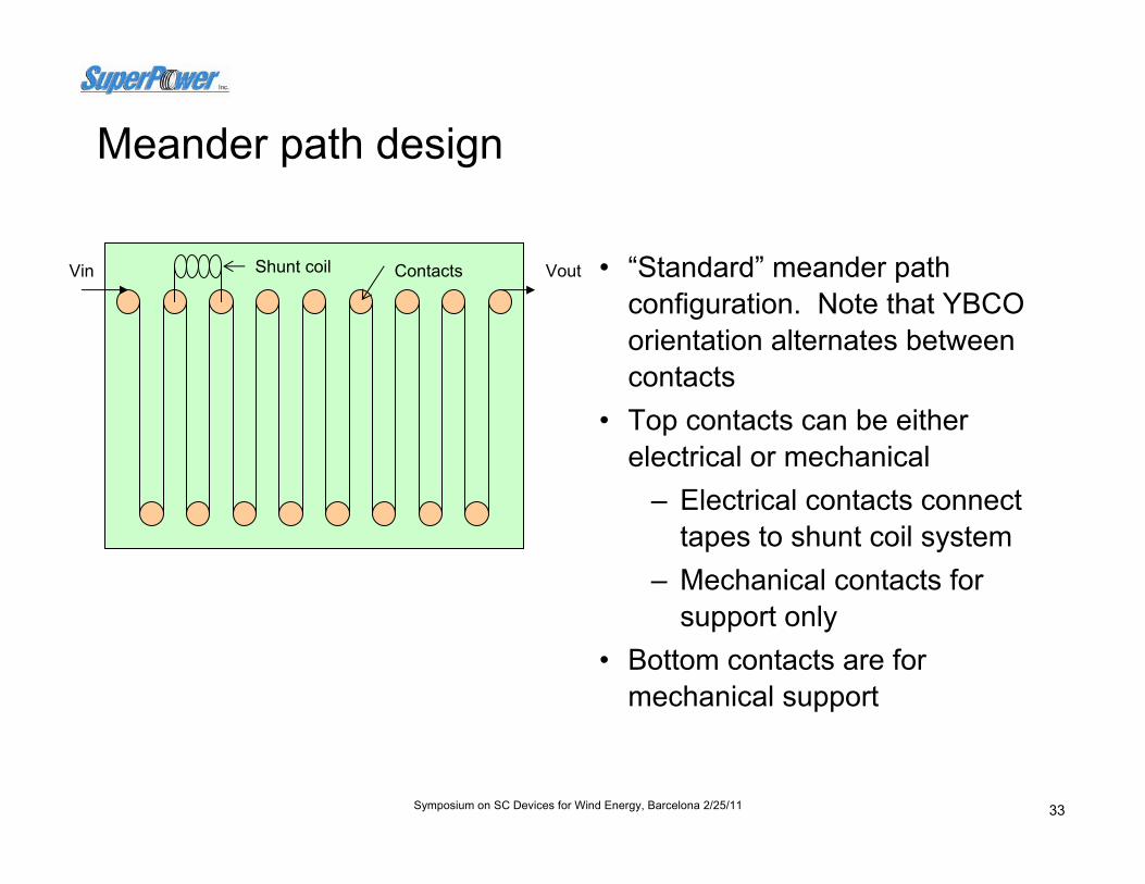
Meander path design
• “Standard” meander path configuration. Note that YBCO orientation alternates between contacts
• Top contacts can be either electrical or mechanical
– Electrical contacts connect tapes to shunt coil system
– Mechanical contacts for support only
• Bottom contacts are for mechanical support
Vin VoutShunt coil Contacts

34Symposium on SC Devices for Wind Energy, Barcelona 2/25/11
2G RUL capabilities tested at KEMA (2008)• “Standard” SC12100
2G tapes used• Test conditions
- 37 kA fault- follows AEP
sequence
• Test variables- Shunt impedance- Number of parallel
tapes - System voltage
(v/cm/tape)- Load Current
16 Tapes8 Tapes
4 Tapes100V
200V
250V
300V
0
50000
100000
150000
200000
250000
Load Pow er (VA)
Total Recovered Power, 2x5 cycles Faults at 37kA with 10 mOhm
Parallel Tapes
Voltag
e

35Symposium on SC Devices for Wind Energy, Barcelona 2/25/11
1st SFCL Module Manufacturing
5th InternalInstallation
2nd Assemblyof Supports
3rd Assembly of Connections
4th ModuleInstallation
Current SFCL module manufacturing and assembly

36Symposium on SC Devices for Wind Energy, Barcelona 2/25/11
4.16 kV utility bus
0…4.16 kV / 5 MVA experimental bus
AC current reference
from RTDS
AC Voltage feedback to
RTDS
FSU-CAPS testing power in 2009
SFCL modules
Real Time SimulatorRTDS
0-480 V / 1.5 MVA experimental AC bus
SFCL modules
5 MW Converter “Amplifier“
5 MVA power available in 2009
37Symposium on SC Devices for Wind Energy, Barcelona 2/25/11
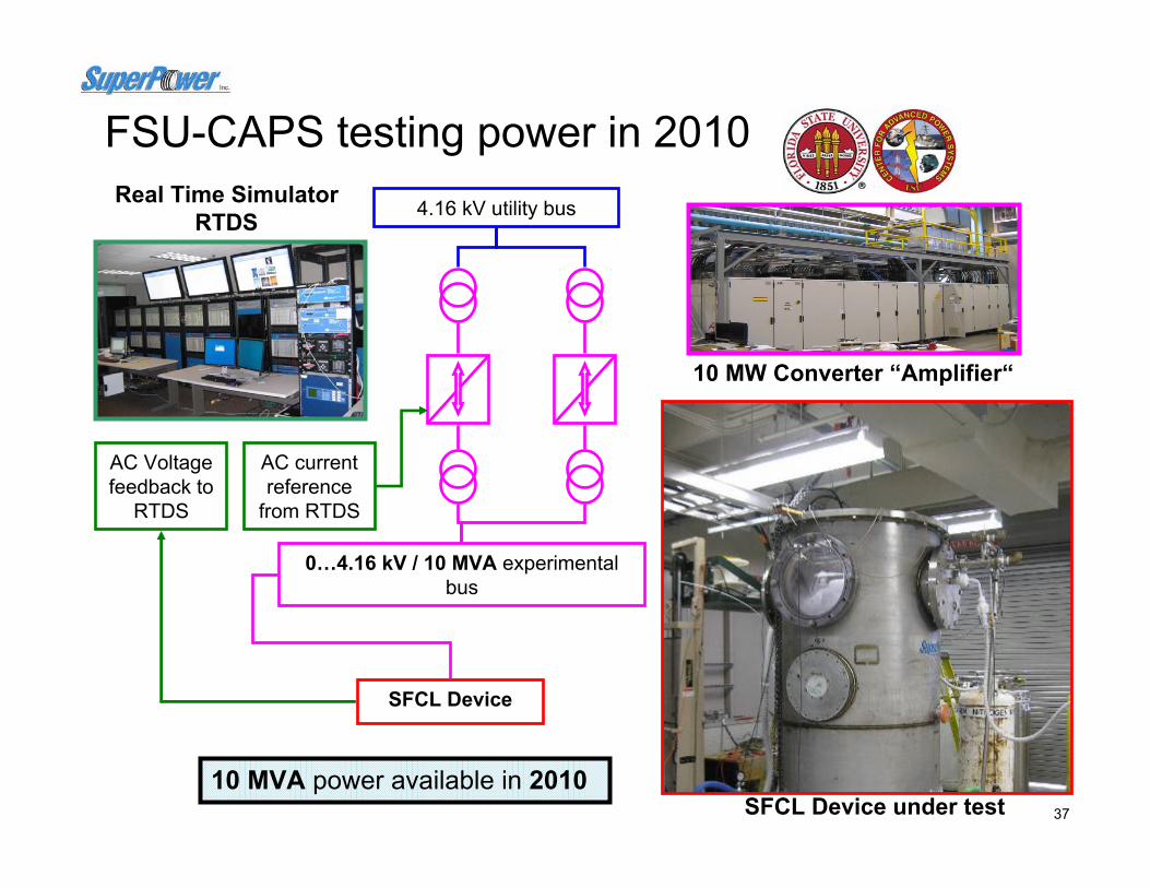
4.16 kV utility bus
0…4.16 kV / 10 MVA experimental bus
AC current reference
from RTDS
AC Voltage feedback to
RTDS
FSU-CAPS testing power in 2010
SFCL Device
Real Time SimulatorRTDS
10 MW Converter “Amplifier“
SFCL Device under test10 MVA power available in 2010

38Symposium on SC Devices for Wind Energy, Barcelona 2/25/11
Limited current with a single 2 tape circuit in a module
Prospective, Limited, Shunt and Tape Current
-25
-20
-15
-10
-5
0
5
10
15
20
25
0 0.016 0.032 0.048 0.064 0.08
Time (s)
Cur
rent
(kA
)
I ShuntI LimitedI SuperconductorI Prospective
65% Fault Reduction
65% Fault reduction at 1st peak with 2 tape circuit for a prospective of 26kA

39Symposium on SC Devices for Wind Energy, Barcelona 2/25/11
Cur
rent
(kA
) ~ 65% Fault Reduction
A single circuit of 2 tapes in a SFCL module will limit 65% of 1st peak fault in the entire voltage range (up to 25kA prospective tested at CAPS)
Limited current for a 2 tape circuit vs. voltage

40Symposium on SC Devices for Wind Energy, Barcelona 2/25/11
Cur
rent
(kA
)
48% Reduction
65% Reduction
45% Reduction
Current at different frequencies play a critical role in tape performance due to eddy current, skin depth on tape and non-homogeneous inductance at quenching.
Peak current for 2 tapes vs. voltage and frequency

41Symposium on SC Devices for Wind Energy, Barcelona 2/25/11
Normal Voltage Range @ 77K
(52%)
Quench
Open Bath (77 K) Voltage “Limit”
Normal Voltage Sub-Cooled
Increase (48%)
32% Current Increase
77 KSub-cooled
Total Extended Sub-Cooled Normal Voltage Range (100%)
Extended Sub-Cooled Voltage “Limit”
Sub-cooled conditions improved 48% voltage (192% increase) and 32% current (132%), a total of ~253% increase in power.
Peak current per tape and voltage for sub-cool and 77K
42Symposium on SC Devices for Wind Energy, Barcelona 2/25/11
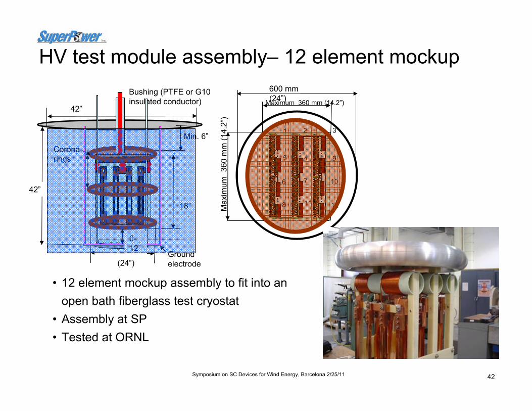
HV test module assembly– 12 element mockup
• 12 element mockup assembly to fit into an open bath fiberglass test cryostat
• Assembly at SP • Tested at ORNL
10
9
321
5 4
6 7
8 11 12
600 mm (24”)Maximum 360 mm (14.2”)
Max
imum
360
mm
(14.
2”)
Bushing (PTFE or G10 insulated conductor)
(24”)
Min. 6”
42”
42”
18”
Corona rings
Ground electrode
0-12”

43Symposium on SC Devices for Wind Energy, Barcelona 2/25/11
2G FCL – high voltage test rigFEA results shows how the stress shield ring can be used to reduce stresses in sharp edge geometries
Sharp 2G element and connector edges
Using stress Shield rings
1.611.551.70Yes6101.651.621.73Yes68
> 4.5> 4.6> 6 .5No66
1.661.751.81Yes661.742.052.07Yes642.033.033.03Yes622.585.005.00Yes613.448.938.93Yes60.5
E y @ 100 kV [kV /m m
Ex @ 100 kV [kV /m m
Em @ 100 kV [kV /m m ]
Shie ld [Yes/N o
]
Axial gap [in ]
Radia l gap [in ]
1 .611.551.70Yes6101.651.621.73Yes68
> 4.5> 4.6> 6 .5No66
1.661.751.81Yes661.742.052.07Yes642.033.033.03Yes622.585.005.00Yes613.448.938.93Yes60.5
E y @ 100 kV [kV /m m
Ex @ 100 kV [kV /m m
Em @ 100 kV [kV /m m ]
Shie ld [Yes/N o
]
Axial gap [in ]
Radia l gap [in ]

44Symposium on SC Devices for Wind Energy, Barcelona 2/25/11
High voltage test requirements for Alpha
• Configurations for impulse testing: – Impulse terminal A wrt to ground, with B
open– Impulse terminal B wrt to ground with A open– Tie A & B together and impulse wrt to
ground
A B
Based on ANSI Transformer C57.12.00 Table 6Switching Impulse
Acceptance criteria establishedPartial Discharge
Based on ANSI Transformer C57.12.00 Table 6Chopped Wave
Based on ANSI Reactor C57.16 Table 5 BIL Lightning Impulse
Based on ANSI Transformer C57.12.00 Table 6Partial Discharge
Based on ANSI Breaker C37.06 Table 460Hz Withstand
Proposed SFCL RequirementTests to be Conducted
Tests based on typical 138kV requirements for Breakers, Transformers & Current Limiting Reactors
Based on input from AEP and NEETRAC Members
Test sequence will follow transformer standard
Normal Impulse Wave Shape
Expected MFCL Wave Shape Due to VeryLow Impedance
It is not possible to achieve standard BIL test waveforms across the terminals - See figure below

45Symposium on SC Devices for Wind Energy, Barcelona 2/25/11
Outline
• 2G HTS for SC Applications
• Projects– 2G HTS SMES– FCL Transformer– FCL Module Development– HTS Cable– HTS Generator– Other
• Summary

46Symposium on SC Devices for Wind Energy, Barcelona 2/25/11
Albany Cable Project - Program Overview– 350m long - 34.5kV - 800Arms - 48MVA– Cold dielectric, 3 phases-in-1 cryostat, stranded copper core design– Two Phases – Phase I - 320m + 30m BSCCO
– Phase II - 30m BSCCO replaced by 30m YBCO cable
Supported by Federal (DOE) and NY State (NYSERDA) Funds
Design, construct and operate the Cryogenic Refrigeration System, and provide overall cable remote monitoring and utility interface
Design, build, install, and test the HTS cable, terminations, & joint
Host utility, conventional cable & system protection, system impact studies
Project Manager; Site infrastructure, Manufacture of 2G HTS wire

47Symposium on SC Devices for Wind Energy, Barcelona 2/25/11 47
Demonstration of the world’s first device made with 2G HTS conductor in a live power grid
350 m cable made with 30 m segment of 2G HTS thin film tape was energized in the grid in January 2008 & supplied power to 25,000 households in Albany, NY
Cu StrandedWire Former
Electric Insulation(PPLP + Liquid Nitrogen)
Stainless Steel DoubleCorrugated Cryostat
2G HTS wire(2 shield Layers)
2G HTS wire(3 conductor Layers)
Installation at Albany Cable site (Aug. 5, 2007)

48Symposium on SC Devices for Wind Energy, Barcelona 2/25/11
2G HTS wire cable winding
3 core stranding
Power transmission cable manufactured by SEI with SuperPower 2G HTS conductorBenefits• 5 (AC) to 10 (DC) times more capacity than comparable conventional cables• Can be used in existing underground conduits saves trenching costs• Liquid nitrogen coolant is also dielectric medium (no oil)• Greatly reduced right-of-way (25 ft for 5 GW, 200 kV compared to 400 feet for
5 GW, 765 kV for conventional overhead lines)• Operating at high currents, can obviate the need for step-up / step down transformers • Can be used on conventional equipment with minor modifications

49Symposium on SC Devices for Wind Energy, Barcelona 2/25/11
Replacement of 30 meter Section with YBCO Cable (Phase II) [ 30m cable Installation ]
[ Joint Re-assemble�BSCCO-YBCO�]
[ Termination Re-assemble ]

50Symposium on SC Devices for Wind Energy, Barcelona 2/25/11
-0.5
0
0.5
1
1.5
2
0 500 1000 1500 2000 2500 3000Current (A, DC)
Elec
trica
l Fie
ld(u
V/cm
)
Core-1Core-2Core-3
Ic Criterion (1uV/cm)
-0.5
0
0.5
1
1.5
2
0 500 1000 1500 2000 2500 3000Current (A, DC)
Elec
trica
l Fie
ld(u
V/cm
)
Core-1Core-2Core-3
Ic Criterion (1uV/cm)
Sample: 3 meter 3-Core• Ic (Conductor) = Approx. 2660 – 2820A (DC, 77K, 1uV/cm)• Ic (Shield) = Approx. 2400 – 2500A (DC, 77K, 1uV/cm)
Conductor Shield
Very good match between test results and design values
YBCO Cable - Critical Current Measurement

51Symposium on SC Devices for Wind Energy, Barcelona 2/25/11
Re-connected with live network and back in service (Phase-II)
• HTS Cable System re-connected with live network; back in service Jan. 8, 2008• HTS Cable System was operated successfully in unattended condition• Long-term Operation completed successfully end of April 2008
66
67
68
69
70
71
1/7 1/14 1/21 1/28 2/4 2/11 2/18 2/25 3/3 3/10 3/17 3/24 3/31
Date & Time
Tem
pera
ture
[K]
0
4
8
12
16
20
Tran
smitt
ed E
lect
ricity
[MVA
]
Energizedon Jan.8, 08
Cable Outlet Temperature
Cable Inlet Temperature
Transmitted Electricity
Completed End of April, 2008

52Symposium on SC Devices for Wind Energy, Barcelona 2/25/11
0.001
0.01
0.1
1
100 1000 10000Loading Current (Arms, 60Hz)
AC
loss
(W/m
/pha
se)
Measured value
Sample: 2.5 meter single coreCurrent loading: go & return through conductor and shieldMeasuring: Lock-in amplifier with electrical 4 terminals
0.34 W/m/ph @ 800 ArmsSlightly better result than the
1 meter test sample core
AC Loss Measurement

53Symposium on SC Devices for Wind Energy, Barcelona 2/25/11
Outline
• 2G HTS for SC Applications
• Projects– 2G HTS SMES– FCL Transformer– FCL Module Development– HTS Cable– HTS Generator / Motor
• Summary

54Symposium on SC Devices for Wind Energy, Barcelona 2/25/11
HTS Coils for Motors and Generators
• Industrial Applications– Wind and hydro-electric generators,
petroleum refining, machine tool operation
• Military Applications– Navy: all electric ship– Air Force: electrically-driven power aboard
military aircraft, airborne active denial systems, self-protect systems, directed energy weapons
• Distinct Advantages:– Improved efficiency, including CRS for cooling the devices– 50% reduction in full load losses– Improved power quality enabling faster switching speeds– 30% - 50% smaller and lighter, heat disposal of less concern– Inherently quiet, no iron teeth– Higher magnetic fields – greater power density

55Symposium on SC Devices for Wind Energy, Barcelona 2/25/11
Superconducting generators offer benefits for wind energy production
• High power generators under development for wind turbines and off-shore power production.
– More economical– Less # of generators to maintain for same power generation– Superconducting generators can mitigate voltage fluctuation enhance power
system stability, larger reactive power output capacity1
• Cooling of superconductors consumes 1% of produced power• Superconductors can be used in auxiliary systems such as Superconducting Magnetic
Energy Storage (SMES) for smoothing wind generator output2
• Superconducting generators can be beneficial in high power wind turbines– Reduce generator weight & volume
by 50% or more (above 5 MW, conventional generators are too heavy)
– More efficient– Direct drive without gearbox
possible.– No Rare Earth magnet limitations
1 Sakamoto et al. 15th PSCC, Liege, 22-26 August 2005
2 Takahashi et al. DOI 10.1109/ICEMS.2007.4412245

56Symposium on SC Devices for Wind Energy, Barcelona 2/25/11
HTS generator project with the NavyBenefits:• Improved efficiency, including the cryogenic refrigeration system required for
cooling the devices, resulting in a 50% reduction in full load losses• Improved power quality that enables faster switching speeds• Improved ship configuration flexibility because devices are about 30% lighter
and 50% smaller and heat disposal is less of a concern• Inherently quiet since they do not need iron teeth, a major source of structure-
borne noise• Higher magnetic fields allow for greater power density
Cryocoolers Brushless Exciter
Transfer Coupling
Rotor with HTS CoilsStator EndWinding
Torque Tubes Stator EndTurn Support
Back- Iron
Drive Shaft
HTS Generator Concept
• SuperPower• Baldor Electric• General Dynamics-
Electric Boat• Naval Surface Warfare
Center (Philadelphia)• Naval Research Lab• ORNL
• SuperPower• Baldor Electric• General Dynamics-
Electric Boat• Naval Surface Warfare
Center (Philadelphia)• Naval Research Lab• ORNL

57Symposium on SC Devices for Wind Energy, Barcelona 2/25/11
Coil Applications: World record performance achieved in high field coil constructed with 2G HTS wire
2009: 27.4 Tesla at 4.2K in 19.89 Tesla background field2008: 33.8 Tesla at 4.2K in 31 Tesla background field2007: 26.8 Tesla at 4.2K in 19 Tesla background field2006: 2.4 Tesla at 64K in self field
Nuclear magnetic resonance (NMR)spectroscopy2009 Insert Coil
>>>

58Symposium on SC Devices for Wind Energy, Barcelona 2/25/11
Other applications for HTS
Medical Devices: MRI, NMR,
Proton Therapy
Military: Navy’s Electric Ship, Air Force
Space: Propulsion systems, radiation shielding
Transportation: Maglev Trains

59Symposium on SC Devices for Wind Energy, Barcelona 2/25/11
Outline
• 2G HTS for SC Applications
• Projects– 2G HTS SMES– FCL Transformer– FCL Module Development– HTS Cable– HTS Generator / Motor
• Summary

60Symposium on SC Devices for Wind Energy, Barcelona 2/25/11
Launch of superconducting devices in energy applications has fueled growth of 2G HTS demands
• After 20+ years since its discovery, HTS is now inserted in devices in electric power devices and in other industrial devices
• Rapid growth of HTS market projected as wire cost is reduced andprice: performance continues to improve
• The 2G HTS community is rapidly scaling capacity to meet the increasing demands for conductor

61Symposium on SC Devices for Wind Energy, Barcelona 2/25/11
Questions?
Thank you for your interest!
For further information about SuperPower, please visit us at: www.superpower-inc.com
or e-mail: [email protected]