2016 FSAE Electric Vehicle Pedal Assembly Design
40
e University of Akron IdeaExchange@UAkron Honors Research Projects e Dr. Gary B. and Pamela S. Williams Honors College Spring 2016 2016 FSAE Electric Vehicle Pedal Assembly Design Evan Beery [email protected] Please take a moment to share how this work helps you through this survey. Your feedback will be important as we plan further development of our repository. Follow this and additional works at: hp://ideaexchange.uakron.edu/honors_research_projects Part of the Automotive Engineering Commons is Honors Research Project is brought to you for free and open access by e Dr. Gary B. and Pamela S. Williams Honors College at IdeaExchange@UAkron, the institutional repository of e University of Akron in Akron, Ohio, USA. It has been accepted for inclusion in Honors Research Projects by an authorized administrator of IdeaExchange@UAkron. For more information, please contact [email protected], [email protected]. Recommended Citation Beery, Evan, "2016 FSAE Electric Vehicle Pedal Assembly Design" (2016). Honors Research Projects. 389. hp://ideaexchange.uakron.edu/honors_research_projects/389
Transcript of 2016 FSAE Electric Vehicle Pedal Assembly Design

The University of AkronIdeaExchange@UAkron
Honors Research Projects The Dr. Gary B. and Pamela S. Williams HonorsCollege
Spring 2016
2016 FSAE Electric Vehicle Pedal Assembly DesignEvan [email protected]
Please take a moment to share how this work helps you through this survey. Your feedback will beimportant as we plan further development of our repository.Follow this and additional works at: http://ideaexchange.uakron.edu/honors_research_projects
Part of the Automotive Engineering Commons
This Honors Research Project is brought to you for free and open access by The Dr. Gary B. and Pamela S. WilliamsHonors College at IdeaExchange@UAkron, the institutional repository of The University of Akron in Akron, Ohio,USA. It has been accepted for inclusion in Honors Research Projects by an authorized administrator ofIdeaExchange@UAkron. For more information, please contact [email protected], [email protected].
Recommended CitationBeery, Evan, "2016 FSAE Electric Vehicle Pedal Assembly Design" (2016). Honors Research Projects. 389.http://ideaexchange.uakron.edu/honors_research_projects/389

5/5/2016
Honors Senior Design Project
Pedal Assembly
Beery, Evan ADVISOR: DR. SHAO WANG

Table of Contents
Abstract ......................................................................................................................................................... 1
Acknowledgements ....................................................................................................................................... 2
Introduction .................................................................................................................................................. 3
Conceptual Design ........................................................................................................................................ 5
Embodiment Design .................................................................................................................................... 13
Detail Design ............................................................................................................................................... 16
Discussion.................................................................................................................................................... 33
Conclusion ................................................................................................................................................... 34
References .................................................................................................................................................. 35
Appendix A – Rules and Regulations ........................................................................................................... 36

P a g e | 1
Honors Senior Design Evan I. Beery Mechanical Engineering
Abstract
The purpose of this project was to design and produce the pedal box assembly for the
electric formula SAE racecar team’s 2016 racecar. To complete this project, a working 3D
model and corresponding blueprints were created. Materials were selected, machined, and
assembled. FEA software was used to verify the design. The final step was manufacturing and
assembling all the components together and placing them in the racecar. The precision
machining was completed on campus at the University of Akron, and was considered a vital
measurable of the project.
This assembly allows for the actuation of two aluminum pedals. One pedal applies force
to the master cylinders used in the hydraulic braking system. A balance bar is used to allow for
the calibration of the hydraulic breaking system. The amount of force applied relative between
the front wheels and rear wheels will be calibrated during the testing of the racecar. The other
pedal actuates linear potentiometers that are used to gage the acceleration of the racecar. The
linear potentiometers will be integrated into the electrical system of the car. The assembly is
robust and adaptable.
The result of this project is a completed pedal assembly. The assembly is in alignment
with the Electric Vehicle team’s goal of continual design and manufacturing improvement. The
final assembly improves upon the previous year’s design as well as alleviating several concerns
from the previous year. It has successfully integrated with the hydraulic breaking systems as
well as other subsystems; particularly the frame and electrical systems.
This report explores several different conceptual pedal design solutions. Different basic
sketches were created to help visualize the varied ideas and gain input from other potential
drivers of the car. The integrating subsystem engineers were consulted with throughout design
and manufacturing to insure successful incorporation into the car. This report documents the
design process, describes the manufacturing process, and records lessons learned throughout
the project.

P a g e | 2
Honors Senior Design Evan I. Beery Mechanical Engineering
Acknowledgements
I would like to extend a special thanks to my family for their loving support and
motivation in this project and throughout my academic journey. Also a big thank you to Mr.
Steve Gerbitz for all the time he spent teaching me the skills and techniques to manufacture
this project. Lastly, thank you to the electric vehicle team for the encouragement,
brainstorming sessions, and allowing me to be a member of the team.

P a g e | 3
Honors Senior Design Evan I. Beery Mechanical Engineering
Introduction
There are few things more exciting for car enthusiasts than racing. Persons that do not
have a background in vehicular design do not often take the time to think about the one of the
most important interactions a driver has with a car; the pedal assembly. Race teams often
design their pedals specifically for a particular driver. The 2016 electric racecar will be driven by
many different drivers. This does not diminish the importance of a well-designed pedal
assembly.
Background:
The University of Akron’s electric formula SAE race team is working on only its third car.
The team is still developing best practice designs and developing their own standards. There
are many styles of pedal assembly’s in production today. This report explores three basic
concepts for the pedals.
The first is having the pedals actuating below the axis of rotation. This concept is seen
regularly in consumer vehicles. This type of design can be easier to adjust. A disadvantage in
implementing it into the electric racecar is the cost and manufacturability. Another concept
that is explored is having the axis of rotation near to the center of the pedal. This allows for a
spring to pull the pedal back to its resting position after being actuated. This concept is cost
effective as springs are very cost effective compared to a pneumatic spring. A disadvantage is
that axis of rotation is near to the location of force input from the driver. Many drivers do not
prefer this. A third concept is to design the pedal to actuate above the axis of rotation. This
concept can be less cost effective since it costs more money to produce a mechanism to return
the accelerator pedal to the resting position.
There are undoubtedly many more ideas of how to design a pedal assembly. Since
these pedals were to be manufactured it was also important that any design could be
realistically produced. The pedal concepts were explored as they were deemed most feasible
and effective to produce and implement into the 2016 electric vehicle racecar (1).

P a g e | 4
Honors Senior Design Evan I. Beery Mechanical Engineering
Principles of Operation:
The principles of operation are important to take into consideration. The goal is to
create an optimal pedal assembly based on the electric vehicle team’s needs. These needs
include envelope, weight, durability, adjustability, manufacturability, and cost. The final
assembly must be effectively integrated into the frame and interact with the hydraulic brake
system and the electrical system of the racecar. The pedal assembly must be in accord with the
2015-16 Formula SAE® Rules (2). Appendix A provides a list of the rules and regulations
governing the pedal assembly.
Product Definition:
The final pedal assembly must be manufactured and satisfactorily transfer the force
from applied from the driver into the hydraulic break system. It also must effectively provide
minimal difference consistently between two linear potentiometers as stated in Rule EV2.3.4
and EV2.3.6. The assembly also needs to conform to all safety rules as well as implementing a
brake over-travel switch according to rule T7.3.1. This switch must be designed so that if the
hydraulic break systems malfunctions, and the brake pedal over travels, the switch will be
actuated resulting in the shutdown system being activated. The final product will allow for the
hydraulic system to operate as well as the electrical of the car.

P a g e | 5
Honors Senior Design Evan I. Beery Mechanical Engineering
Conceptual Design
In the 2016 electric vehicle racecar, the team wanted to improve the overall weight of
the racecar. As a result it was desired to have a pedal assembly with a smaller envelope. The
electrical engineers also requested that the linear potentiometers have a greater repeatability.
This means that when the accelerator pedal was pressed, that the difference between the two
potentiometers must be minimal. This would require a robust design that limits any movement
of the accelerator pedal other than in the direction of actuation. The design of the pedal
assembly is governed by envelope, weight, durability, adjustability, manufacturability, and cost.
These design factors are all woven together and tradeoffs had to be made.
Segmentation Techniques:
Figure #1 displays the pedal assembly’s functional flow. After developing a firm
understanding with and the basic goals of the project, brainstorming could be done to develop
concepts for the different aspects of the assembly. Figure #2 displays an objective tree which is
a result of such brainstorming. It establishes the central objective and the supporting
components that significantly impact the design.
Figure #1 – Functional Diagram

P a g e | 6
Honors Senior Design Evan I. Beery Mechanical Engineering
Figure #2 – Objective Tree
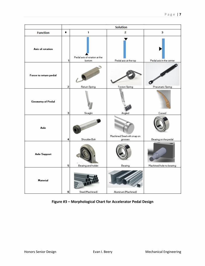
Morphological chart:
Several different concepts were developed for the accelerator pedal design. Ideas were
taken from all members of the team and other vehicle designs (8). The brake pedal is
constrained by the master cylinders and balance bar. The orientation of the brake pedal will
therefore follow the orientation of the accelerator pedal. The master cylinders return the
brake pedal to its resting position. A morphological chart for the accelerator pedal is shown in
Figure #3.
P a g e | 7
Honors Senior Design Evan I. Beery Mechanical Engineering
Figure #3 – Morphological Chart for Accelerator Pedal Design

P a g e | 8
Honors Senior Design Evan I. Beery Mechanical Engineering
Concept Sketches:
From the morphological charts concept sketches can be generated. These sketches
communicate graphically the general look and feel of the accelerator design with minimal
actual engineering or developmental background. They allowed for input from other members
of the team and knowledgeable persons.
Concept Sketch #1
Concept sketch #1, option A, includes an axis of rotation at the bottom of the pedal with
a torsion spring to return the pedal. The axle is made up of machined steel with snap on clips
to retain it. The pedal is straight and made up of steel material and a bearings in holders
support the axle.
Concept sketch #1, option B, includes an axis of rotation at the bottom of the pedal with a
torsion spring to return the pedal. The axle is made up of a shoulder bolt with a nylon lock nut
to retain it. The pedal is straight and made up of aluminum material and has a machined hole
to support the axle with no bearing.

P a g e | 9
Honors Senior Design Evan I. Beery Mechanical Engineering
Concept Sketch #2
Concept Sketch #2 consists of an axis of rotation in the center of the pedal with a return
spring returning the pedal. The pedal is straight and consists of aluminum material. The axle is
made up of a bearing on the pedal.
Concept Sketch #3

P a g e | 10
Honors Senior Design Evan I. Beery Mechanical Engineering
Concept Sketch #3 constitutes an axis of rotation at the bottom of the pedal with a
pneumatic spring returning the pedal. The axis of rotation is a shoulder bolt inserted through a
machined hole in the aluminum straight pedal with no bearing.
Concept Sketch #4
Concept Sketch #4 comprises an angled steel pedal with a torsion spring installed to
return the pedal. The axle is machined steel with snap on clips to retain it supported by
bearings in holders.
Concept Sketch #5

P a g e | 11
Honors Senior Design Evan I. Beery Mechanical Engineering
Concept Sketch #5 entails a steel curved pedal utilizing a pneumatic return spring to
return the aluminum pedal. The axil is made up of a shoulder bolt through a machined hole
with no bearing.
Weighted Decision Matrix:
To help to screen the concepts brainstormed, a weighted decision matrix was used.
Figure #4 displays the origin of the weight assigned to each factor(7). The weights were
assigned based on how important each respective aspect was to the overall design. Figure #4
displays the origin of the weights for the weights used in the weighted decision matrix
assessment as shown in figure #5. Reference Figure #6 for the decision matrix showing
unweighted assessment.
Figure #4 – Origin of the Decision Matrix Weights

P a g e | 12
Honors Senior Design Evan I. Beery Mechanical Engineering
Figure #5 – Decision Matrix Displaying Weighted Assessment
Figure #6 – Decision Matrix Displaying Unweighted Assessment
The decision matrix is based on a range of scores from 1 to 5; a score of 5 being the
most desirable while a score of 1 being the least desirable. From the weighted decision matrix
in Figure #5 it can be determined that Concept #3 is the best option since it has the highest
score of 3.8. Therefore, the pedal assembly design will consist of an axis of rotation at the

P a g e | 13
Honors Senior Design Evan I. Beery Mechanical Engineering
bottom of the pedal with a pneumatic spring returning the pedal. The axis of rotation will be a
shoulder bolt inserted through a machined hole in the aluminum straight pedal with no
bearing.
Embodiment Design
With the basic concept of the pedal assembly established, it was then to possible to
begin the development of the design in accordance with the technical and economic criteria
established.
Envelope:
The design needed to be robust and adaptable to different drivers. The racecar must be
able to accommodate heights from the 5th percentile female to the 95th percentile male.
Section T3.10.4 of the FSAE rulebook sets the measurement standards to determine this.
Figure #7 is taken from the rulebook. With the seat in the rearmost position and the pedals in
the foremost position a radius of 915 mm minimum must be met.
Figure #7
In conjunction with the frame lead on the team, a depth of 5 inches was agreed upon. This was
the first design constraint. The maximum width of the assembly was given by the frame design
as 12 inches. The height, also constrained by the frame, was 12.5 inches. The pedal assembly
needed to fit in a 5 inch by 12 inch by 12.5 inch cube.

P a g e | 14
Honors Senior Design Evan I. Beery Mechanical Engineering
Durability
According to T7.1.9 in the SAE rulebook the brake pedal must be fabricated from steel,
aluminum, machined steel, or machined aluminum. This greatly narrowed down material
selection. Rule T7.1.8 states that the brake pedal also must be able to withstand a force of
2000 N without any failure to the pedal or the pedal assembly. At competition this will be
tested by a judge sitting normally in the car and pressing the pedal with the maximum force
that can be exerted.
Adjustability:
It is important that when testing the car that adjustments can be made to the available
travel of both pedals. The electrical engineers requested that the accelerator pedal have both a
positive and negative stop and that it be adjustable to have complete control over the range of
motion of the linear potentiometers. The brake over travel switch had to be adjustable to allow
for calibration during testing.
Weight:
There was no specific requirement given from the rules or the team as far as the overall
weight of the pedal assembly. However, one of the goals for the 2016 racecar is to reduce the
weight so it is a design constraint that had to be taken into consideration.
Cost:
The cost of the pedal assembly had to be kept at a minimum. Material that was already
on hand was much preferred. The electric vehicle team has several sponsors that donate
manufacturing processes and materials when needed. The master cylinders, balance bar and
the linear potentiometers are reused from the racecar produced in 2015. This helped to reduce
cost, but also constrained the design.
Manufacturability:
The components of the pedal box had to be designed as to alleviate complex
manufacturing as it would be unable to be completed on campus and possibly become very

P a g e | 15
Honors Senior Design Evan I. Beery Mechanical Engineering
costly. Processing had to be limited to machining able to be completed on a mill or lathe.
Components could be sent out to a sponsor for laser cutting or water jetting as well.
Appropriate fasteners had to also be taken into consideration. Article 11 of the rule book
outlines appropriate fasteners. Rule T11.2.1 outlines that for all critical bolts, nuts, and other
fasteners on the braking system must have positive locking mechanisms. Positive locking
mechanisms included safety wiring, cotter pins, nylon lock nuts, and torque lock nuts. Rule
T11.2.2 also specifies that there must be a minimum of two full threads projecting from any
lock nut.
Material Selection
Material selection is limited by the rules to aluminum and steel. There will be a high
amount of bending stress on the pedals in particular while in operation. Both pedals had to be
able to handle large amounts of loads without excessive deformation while still maintaining
reasonable machinability. Preliminarily, 6061 aluminum was chosen as main material to make
up the components of the pedal assembly. 6061 displays desired properties such as a high
strength to weight ratio and good machinability, as well as having stock already on hand and
available.

P a g e | 16
Honors Senior Design Evan I. Beery Mechanical Engineering
Detail Design
For the detailed design, the modeling software SOLIDWORKS 2015 used to generate a
live model of the pedal assembly (3). Also generated were corresponding component drawings.
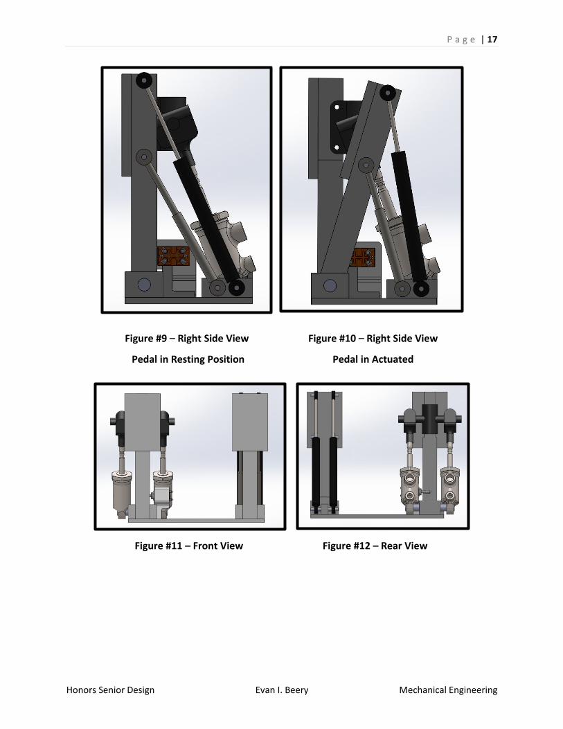
Figure #8 shows the final isometric view of the pedal assembly model. The model allows for the
actuation of the pedals over their respective range of motions. Reference the following figures.
Figure #8 – Isometric View of Final Pedal Assembly
P a g e | 17
Honors Senior Design Evan I. Beery Mechanical Engineering
Figure #9 – Right Side View
Pedal in Resting Position
Figure #10 – Right Side View
Pedal in Actuated
Figure #11 – Front View Figure #12 – Rear View

P a g e | 18
Honors Senior Design Evan I. Beery Mechanical Engineering
Figure #13 – Left Side View
Brake Pedal in Resting Position
Figure #14 – Left Side View
Brake Pedal in Actuated
Figure #15 – Top View
Both Pedals in Resting Positions
Figure #16 – Top View
Both Pedals in Actuated

P a g e | 19
Honors Senior Design Evan I. Beery Mechanical Engineering
Figure #17 – Bottom View
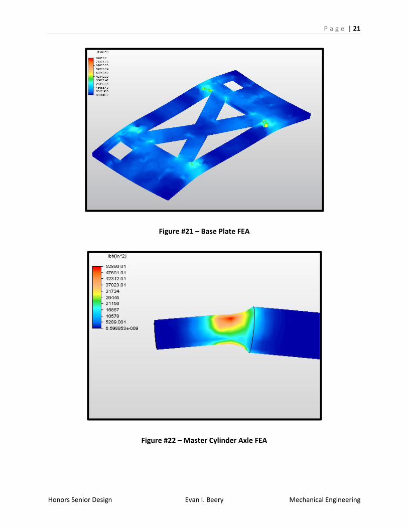
Finite Element Analysis
Finite element analysis (FEA) was used to verify the design for strength, durability, and
deflection (4). The software used was Autodesk Simulation Multiphysics 2013. Per the
regulations, each component of the pedals must withstand a minimum of 2000 Newtons of
force. For the FEA load, a factor of safety of 1.5 was used. Consequently each simulation used
3000 Newtons as the input force. The following figures display the FEA results. 6061 aluminum
has a yield strength of 40,000 psi.
Figure #18 – Pedal Axle Mount FEA

P a g e | 20
Honors Senior Design Evan I. Beery Mechanical Engineering
Figure #19 – Accelerator Pedal FEA
Figure #20 – Master Cylinder Axle Mount FEA
P a g e | 21
Honors Senior Design Evan I. Beery Mechanical Engineering
Figure #21 – Base Plate FEA
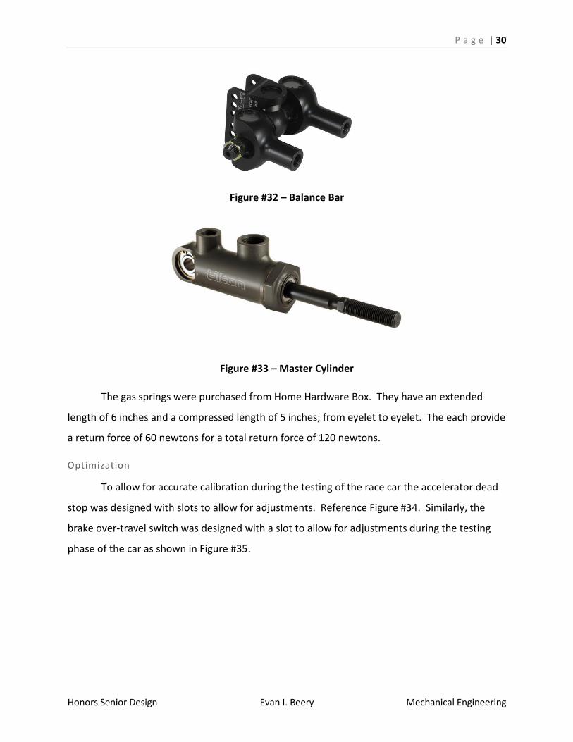
Figure #22 – Master Cylinder Axle FEA

P a g e | 22
Honors Senior Design Evan I. Beery Mechanical Engineering
Note that the master cylinder axle was made for AISI 1045 cold drawn steel which has a
much higher yield strength of 65300 psi.
Figure #23 – Brake Pedal FEA

P a g e | 23
Honors Senior Design Evan I. Beery Mechanical Engineering
Figure #24 – Base Plate Drawing

P a g e | 24
Honors Senior Design Evan I. Beery Mechanical Engineering
Figure #25 – Accelerator Pedal Drawing

P a g e | 25
Honors Senior Design Evan I. Beery Mechanical Engineering
Figure #26 – Brake Pedal Drawing

P a g e | 26
Honors Senior Design Evan I. Beery Mechanical Engineering
Figure #27 – Bracket for Gas Springs and Linear Potentiometers
Figure #28 – Axle Mount

P a g e | 27
Honors Senior Design Evan I. Beery Mechanical Engineering
Figure #29 – Axle for Master Cylinders

P a g e | 28
Honors Senior Design Evan I. Beery Mechanical Engineering
Figure #30 – Master Cylinder Axle Mount

P a g e | 29
Honors Senior Design Evan I. Beery Mechanical Engineering
Standard Components
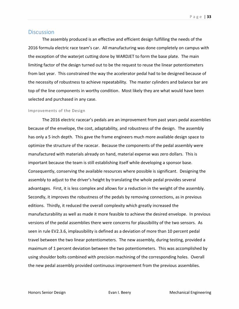
The master cylinders and balance bar were purchased from Tilton racing (5). The
master cylinders have bore diameters of 1 inch. The linear potentiometers were manufactured
by Active Sensors. They are the CLS1322 model (6). Reference Figures #31, #32 & #33. The
hydraulic braking system engineer requested two master cylinders to be incorporated into the
design implementing a balance bar connecting them together. The balance bar allows to
distribute the breaking force inputted between the two master cylinders.
Figure #31 – Linear Potentiometer Specifications
P a g e | 30
Honors Senior Design Evan I. Beery Mechanical Engineering
Figure #32 – Balance Bar
Figure #33 – Master Cylinder
The gas springs were purchased from Home Hardware Box. They have an extended
length of 6 inches and a compressed length of 5 inches; from eyelet to eyelet. The each provide
a return force of 60 newtons for a total return force of 120 newtons.
Optimization
To allow for accurate calibration during the testing of the race car the accelerator dead
stop was designed with slots to allow for adjustments. Reference Figure #34. Similarly, the
brake over-travel switch was designed with a slot to allow for adjustments during the testing
phase of the car as shown in Figure #35.

P a g e | 31
Honors Senior Design Evan I. Beery Mechanical Engineering
Figure #34 - Adjustable Accelerator Dead Stop
Figure #35 - Adjustable Brake Over-Travel Switch
To accommodate heights from the 5th percentile female to the 95th percentile male a set
of 8 holes to be placed in the floor of the car. These eight holes allow the pedal assembly to be
moved into three separate positions. The assembly can simply be unbolted, moved to the
desired location, and reattached.
Manufacturing Methods
The main manufacturing method was machining. WARDJET is a sponsor of the team and
donated waterjet cutting to produce the base plate. All the machined components were made of
aluminum. The main machines used in processing where a Bridgeport mill, drill press, and band saw.
Reference Figure #36.

P a g e | 32
Honors Senior Design Evan I. Beery Mechanical Engineering
Figure #36 – Machining with the Bridgeport Mill
P a g e | 33
Honors Senior Design Evan I. Beery Mechanical Engineering
Discussion The assembly produced is an effective and efficient design fulfilling the needs of the
2016 formula electric race team’s car. All manufacturing was done completely on campus with
the exception of the waterjet cutting done by WARDJET to form the base plate. The main
limiting factor of the design turned out to be the request to reuse the linear potentiometers
from last year. This constrained the way the accelerator pedal had to be designed because of
the necessity of robustness to achieve repeatability. The master cylinders and balance bar are
top of the line components in worthy condition. Most likely they are what would have been
selected and purchased in any case.
Improvements of the Design
The 2016 electric racecar’s pedals are an improvement from past years pedal assemblies
because of the envelope, the cost, adaptability, and robustness of the design. The assembly
has only a 5 inch depth. This gave the frame engineers much more available design space to
optimize the structure of the racecar. Because the components of the pedal assembly were
manufactured with materials already on hand, material expense was zero dollars. This is
important because the team is still establishing itself while developing a sponsor base.
Consequently, conserving the available resources where possible is significant. Designing the
assembly to adjust to the driver’s height by translating the whole pedal provides several
advantages. First, it is less complex and allows for a reduction in the weight of the assembly.
Secondly, it improves the robustness of the pedals by removing connections, as in previous
editions. Thirdly, it reduced the overall complexity which greatly increased the
manufacturability as well as made it more feasible to achieve the desired envelope. In previous
versions of the pedal assemblies there were concerns for plausibility of the two sensors. As
seen in rule EV2.3.6, implausibility is defined as a deviation of more than 10 percent pedal
travel between the two linear potentiometers. The new assembly, during testing, provided a
maximum of 1 percent deviation between the two potentiometers. This was accomplished by
using shoulder bolts combined with precision machining of the corresponding holes. Overall
the new pedal assembly provided continuous improvement from the previous assemblies.

P a g e | 34
Honors Senior Design Evan I. Beery Mechanical Engineering
Conclusion The pedal assembly produced effectively satisfies the project proposal. It allows for the
operation of the hydraulic breaking system and the activation of the electrical acceleration
system with a high level of repeatability. The costs of the project were minimal. The assembly
is adjustable, accommodates an appropriate height range of persons, and correctly fits within
the frame of the racecar.
This project proved both challenging and engaging. At the deadline for submission of
this report, the 2016 electric SAE racecar has not been manufactured sufficient to provide live
testing results in this report. This is unfortunate, as it was greatly anticipated to analyze the
results and would have provided valued experience. Many skills were developed such as FEA,
SolidWorks 3D modeling, vehicle braking theory, practical machining abilities, and machine
operation skills. My favorite aspect of the project was learning custom machining techniques
and learning to operate the machines.
I look forward to the installation, testing, and calibration of the pedal assembly in the
2016 electric SAE racecar. The team expects to compete at two separate Formula SAE
competitions this summer.

P a g e | 35
Honors Senior Design Evan I. Beery Mechanical Engineering
References
(1) Richard Gross, “Chapter 9: Design of A Braking System”, FSAE Racing Vehicle Dynamics
(2) 2015-16 Formula SAE Rules. Available:
http://fsaeonline.com/page.aspx?pageid=e179e647-cb8c-4ab0-860c-ec69aae080a3
(3) Solidworks, 2015 Educational Edition
(4) Autodesk Simulation Mulitphysics, 2013 Educational Edition
(5) Tilton Racing. Available: http://tiltonracing.com/
(6) Active Sensors. Available: http://www.activesensors.com/
(7) Dieter, George and Schmidt, Linda. Engineering Design. 5th ed. New York: McGraw-
Hill, 2013. Print.
(8) Top Tech High Performance Brake Systems. Available: http://www.stoptech.com/

P a g e | 36
Honors Senior Design Evan I. Beery Mechanical Engineering
Appendix A – Rules and Regulations

P a g e | 37
Honors Senior Design Evan I. Beery Mechanical Engineering