15 Novel Low Inductive … Low Inductive Phase-Leg IGBT Module Eases Paralleling ABB has introduced...
4
www.abb.com/semiconductors POWER MODULES 15 www.power-mag.com Issue 4 2015 Power Electronics Europe Novel Low Inductive Phase-Leg IGBT Module Eases Paralleling ABB has introduced the LinPak, a new open standard phase-leg type IGBT power module with a rating of 1700 V and 2 x 1000 A and a footprint of 100 mm x 140 mm. This type of module will set a new standard in power density. LinPak is designed to accommodate chipsets from 1200 V up to 3300 V. A 3300 V module version will follow early next year. Raffael Schnell, Samuel Hartmann, Dominik Trüssel, Fabian Fischer, Andreas Baschnagel and Munaf Rahimo, ABB Switzerland Semiconductors The LinPak IGBT module features an exceptionally low stray inductance enabling the full utilization of advanced low switching loss IGBT chipsets and even future full Silicon Carbide switch solutions. In addition the LinPak is ideally suited for parallel connection with negligible derating, thus a large range of inverter power can be realized with just one module type. Together with the open standard concept this module fulfills a long wish of the industry in nearly all high power segments such as traction and CAV (commercial, construction and agricultural vehicles), wind-power and solar and industrial drives to name a few. Open standard approach Present IGBT module solutions are at its limit when it comes to advanced and faster IGBT/diode chipsets since the overall stray inductance per switched ampere is too large and high over-voltage will occur. In addition, the available electrical contact area of today’s modules is limited and dates back to times when the packages were rated with 50 % less current than now. Due to today’s modules’ lack of scalability, a large variation of outlines exist to match various inverter ratings. The presented LinPak module concept (Figure 1) addresses all these issues and is published as an open standard, meaning module manufacturers can freely adopt the outline and customers benefit from a standard solution provided by more than one supplier making inverter designs easier. The LinPak offers as well exceptional low stray inductance of 10 nH and an easy customer interface enabling the construction of a very low inductive DC connection with sufficient contact area for the high current densities. This is the ideal fit for the full utilization of the advanced fast IGBT/diode chipsets such as the latest 1700V SPT+ technology. It also makes the package fit for future hybrid and full SIC solutions that come with much higher switching speeds. Besides the very advanced and novel package concept, the LinPak features Figure 1: ABB’s low inductive LinPak IGBT module for reliable high-power converters Figure 2: LinPak scalability
-
Upload
truongcong -
Category
Documents
-
view
219 -
download
5
Transcript of 15 Novel Low Inductive … Low Inductive Phase-Leg IGBT Module Eases Paralleling ABB has introduced...

www.abb.com/semiconductors POWER MODULES 15
www.power-mag.com Issue 4 2015 Power Electronics Europe
Novel Low Inductive Phase-Leg IGBT Module Eases ParallelingABB has introduced the LinPak, a new open standard phase-leg type IGBT power module with a rating of1700 V and 2 x 1000 A and a footprint of 100 mm x 140 mm. This type of module will set a new standardin power density. LinPak is designed to accommodate chipsets from 1200 V up to 3300 V. A 3300 Vmodule version will follow early next year. Raffael Schnell, Samuel Hartmann, Dominik Trüssel,Fabian Fischer, Andreas Baschnagel and Munaf Rahimo, ABB Switzerland Semiconductors
The LinPak IGBT module features anexceptionally low stray inductance enablingthe full utilization of advanced lowswitching loss IGBT chipsets and even
future full Silicon Carbide switch solutions.In addition the LinPak is ideally suited forparallel connection with negligible derating,thus a large range of inverter power can be
realized with just one module type.Together with the open standard conceptthis module fulfills a long wish of theindustry in nearly all high power segmentssuch as traction and CAV (commercial,construction and agricultural vehicles),wind-power and solar and industrial drivesto name a few.
Open standard approachPresent IGBT module solutions are at itslimit when it comes to advanced and fasterIGBT/diode chipsets since the overall strayinductance per switched ampere is toolarge and high over-voltage will occur. Inaddition, the available electrical contactarea of today’s modules is limited anddates back to times when the packageswere rated with 50 % less current thannow. Due to today’s modules’ lack ofscalability, a large variation of outlines existto match various inverter ratings. Thepresented LinPak module concept (Figure1) addresses all these issues and ispublished as an open standard, meaningmodule manufacturers can freely adoptthe outline and customers benefit from astandard solution provided by more thanone supplier making inverter designseasier. The LinPak offers as well exceptional low
stray inductance of 10 nH and an easycustomer interface enabling theconstruction of a very low inductive DCconnection with sufficient contact area forthe high current densities. This is the idealfit for the full utilization of the advancedfast IGBT/diode chipsets such as the latest1700V SPT+ technology. It also makes thepackage fit for future hybrid and full SICsolutions that come with much higherswitching speeds.Besides the very advanced and novel
package concept, the LinPak features
Figure 1: ABB’s low inductive LinPak IGBT module for reliable high-power converters
Figure 2: LinPak scalability
16 POWER MODULES www.abb.com/semiconductors
Issue 4 2015 Power Electronics Europe www.power-mag.com
ultra-sonic welded terminals and anadvanced high reliability solder jointbetween the AIN substrate and AlSiCbaseplate material combination. Inaddition, the well-established hightemperature cycling capable bondingtechnique and the gate-print to substratealuminum bond interconnect from theimproved HiPak are incorporated in thenew LinPak design.
Module scalability and record currentdensityThe LinPak module type offers the benefitthat just one module type is needed pervoltage rating. Thanks to a homogenouscurrent path concept, the module enablesparallel connection of more than fourmodules without any significant derating(Figure 2). The current density offers asolid improvement of more than 10 %
compared to older module types on themarket as shown in Table 1.
Mechanical concept and connectionsThe gate-unit connection is realized with asimple adapter-board (PCB) directlymounted onto the module between ACand DC terminals. The connection to theauxiliary terminals for gate, emitter,collector and thermistor are realized withM3 screws. In addition, four molded M3nuts are positioned in the corners tomechanically fix the adapter board inharsh environmental applications liketraction or CAV. The adapter-boardconnects the modules’ gates and auxemitters in parallel. Thus, many modulescan be connected in parallel with just onegate-unit.The power connections are designed to
enable an absolute symmetrical DC
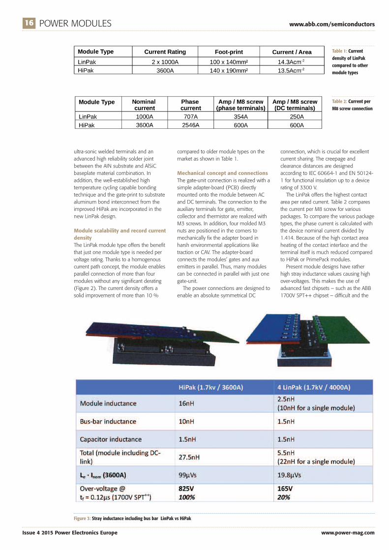
connection, which is crucial for excellentcurrent sharing. The creepage andclearance distances are designedaccording to IEC 60664-1 and EN 50124-1 for functional insulation up to a devicerating of 3300 V.The LinPak offers the highest contact
area per rated current. Table 2 comparesthe current per M8 screw for variouspackages. To compare the various packagetypes, the phase current is calculated withthe device nominal current divided by1.414. Because of the high contact areaheating of the contact interface and theterminal itself is much reduced comparedto HiPak or PrimePack modules.Present module designs have rather
high stray inductance values causing highover-voltages. This makes the use ofadvanced fast chipsets – such as the ABB1700V SPT++ chipset – difficult and the
Table 1: Currentdensity of LinPakcompared to othermodule types
Table 2: Current perM8 screw connection
Figure 3: Stray inductance including bus bar LinPak vs HiPak

www.abb.com/semiconductors POWER MODULES 17
www.power-mag.com Issue 4 2015 Power Electronics Europe
use very fast future SiC solutions close toimpossible.The LinPak is designed to offer the
lowest internal stray inductance current
thus enabling low inductive bus bars.Figure 3 compares the LinPak with a HiPakincluding a bus bar and an assumed DC-capacitor inductance of 1.5 nH. Still when
including the bus bar and capacitor, theover-voltage is below critical levelscompared to the HiPak solution – evenwith fast chipsets. This allows for parallel
Figure 4: Doublepulse test setup
Figure 5: LinPak nominal turn-off switching compared to HiPak (top), LinPak and diode SOA at 125°C (bottom)

18 POWER MODULES www.abb.com/semiconductors
Issue 4 2015 Power Electronics Europe www.power-mag.com
connection up to high current applicationswithout compromising the switchinglosses.
Electrical measurements of prototypemodulesPrototype modules with a current rating of2 x 900 A have been tested in a doublepulse test setup at a realistic customer DC-link with laminated bus bars specificallydesigned for the new LinPak (Figure 4).The measurements fully confirmed what
was expected from the LinPak concept.The tests revealed that an overall DC-linkstray inductance including module, bus barand capacitors of about 25 nH can beachieved already with the prototypemodule. As a result, the over-voltage fromthe switching stays well within themaximum device rating and snappy dioderecovery can be considered as a term ofthe past.Figures 5 (top) shows the LinPak and
HiPak IGBT module switching waveformsat nominal conditions. The LinPak showsvery smooth switching characteristics withthree times lower over-voltage and 20 %less switching losses compared to anequivalent HiPak module. The moduleshave also been tested up to the specified
SOA (Safe Operating Area). Thanks to thelow stray inductance no active clamp wasneeded to limit the IGBT over-voltage andboth, IGBT and Diode SOA show veryclean waveforms (bottom).
Conclusions and outlookThe LinPak is a new open standardmodule that satisfies the requirementsposed by both new advanced fast andhigh current density chipsets as well ascustomer wishes for a flexible and scalableIGBT module that is, in addition, ready forfuture technologies such as SiC devices.The benefits of the novel low strayinductance LinPak IGBT module are clearlydemonstrated and measurementsconfirmed the expectations into the newmodule. Today, the benefits of the new package
enable the customer to profit from thelatest chip technologies with lowinductance for achieving the highestcurrent density. Furthermore, particle freeultrasonic welding of the main terminals,advanced wire bonding including the well-established AIN / AlSiC substrate /baseplate material combination for hightemperature cycling capability areincorporated.
Looking ahead, the new module alsoallows a smooth phase-in of futuretechnologies both on chip level withrespect to Silicon and SiC based devices aswell as on advanced material joiningtechniques as they become available forcost efficient mass production withoutmajor changes in the converter design.
LiteratureRaffael Schnell, Munaf Rahimo “The
Quest for Higher Switching Frequencyand its Implications on SemiconductorSwitches” Proc.PCIM’11 Nuremberg,2011Corvasce C., Kopta A., Rahimo M.T.,
Schnell R, Geissmann S., Vobecky J.;“New 1700V SPT+ IGBT and Diode ChipSet with 175°C Operating JunctionTemperature” EPE’2011, BIRMINGHAM,UK, Aug. 2011R. Schnell, U. Schlapbach, K. Haas, G.
Debled, “Parallel Operation of LoPakModules” Proc. PCIM’03 Nuremberg,2003.G. Borghof “Implementation of low
inductive strip line concept forsymmetric switching in a new highpower module”, PCIM’13 Nuremberg,2013
Name:
Company Name:
Address:
Post Code:
Tel: Total Number of Copies @ £ p+p Total £
Drives S & S Hyd H/B Pne H/B Ind Mot CompH/B H/B Air
DFA MEDIA LTD,
QUANTITY QUANTITY
Hydraulics&Pneumatics There are now 6 of these handy
reference books from the publishers ofthe Drives & Controls and
Hydraulics & Pneumatics magazines.
Published in an easily readable styleand designed to help answer basicquestions and everyday problems
without the need to refer to weightytextbooks.
We believe you’ll find them invaluableitems to have within arms reach.
From the publishers of
QUANTITY QUANTITY QUANTITY
If you would like to obtain additional copies of the handbooks, please completethe form below and either fax it on 01732 360034 or post your order to:
Cheques should be made payable to DFA MEDIA LTD and crossed A/C Payee.Copies of the handbooks are available at £4.99 per copy.Discounts are available for multiple copies. 2-5 copies £4.30, 6-20 copies £4.10, 20+ copies £3.75.
QUANTITY
PRACTICAL ENGINEER’S HANDBOOKSPRACTICAL ENGINEER’S HANDBOOKS
HYDRAULICS
INDUSTRIALMOTORS
SERVOSAND STEPPERS
PNEUMATICS
COMPRESSED AIRINDUSTRIAL
ELECTRIC DRIVES
PLEASE ALLOW UPTO 28 DAYS FOR DELIVERY
192 The High Street, Tonbridge, Kent TN9 1BE
Engineers Handbook, DFA MEDIA LTD,192 The High Street, Tonbridge, Kent TN9 1BE
Postage and Packaging:1-3 copies: £2.99 4-6 copies: £4.99 7 or more copies: £6.99