11OKA through 200KA & 911 OKA through … Series...11OKA through 200KA & 911 OKA through 9150KA W I...
6
11OKA through 200KA & 911 OKA through 9150KA W I Woodhead Aero-Motive® Balancers Balancer Series Service Manual IMPORTANT SAFETY INSTRUCTIONS Please read this manual carefully and follow its instructions. Improper use or failure to follow these instructions could result in serious injury, death or property damage. Operators should be instructed in the safe and proper use and maintenance of this product. Keep this manual for future reference. The following safety precautions call attention to potentially dangerous conditions. 4 DANGER: Immediate hazards which WILL result in severe personal injury or death. A L WARNING: Hazards or unsafe practices which COULD result in severe personal injury or death. CAUTION: Hazards or unsafe practices which MAY result in minor personal injury or product or property damage. NOTE: Instruct operators in the safe, proper use and maintenance. Keep this manual for future reference. INSTALLATION 4 WARNING: Failure to read, understand or follow these instructions could lead to hazards or unsafe practices COULD result in severe personal injury or death. CAUTION: Instruct operators in the safe, proper use and maintenance of this product. Hazards or unsafe practices MAY result in minor personal injury or product or property damage. MOUNTING Hang balancer in the desired location by the shackle provided at the top. The balancer should be suspended directly over work area using an eyebolt or similar device with a break strength exceeding 6 times the combined weight of the balancer and the load it is supporting. Balancer should be mounted in such a manner as to minimize cable contact with the cable guide. If shackle is removed to make the connections, be sure that the nut and cotter pin are properly replaced on the shackle pin. SECONDARY SUPPORT CHAIN 4 DANGER: A secondary safety cable or chain is to be attached to all balancers mounted overhead to prevent balancer from falling. Immediate hazards WILL result in severe personal injury or death. A hole has been provided at the side of the housing to permit installation of a secondary support chain. All balancers mounted over head should have a secondary support chain to protect personnel in case of structure or mounting component failure. Attach one end of secondary support chain or cable to secondary support point (shackle) on balancer. Attach the other end of secondary support chain or cable to a support component other than that which supports the balancer. The chain or cable should be as short as possible allowing the balancer to drop no more than 6 to 12 inches if the primary connection is released. (See Illustration on Page 2) A secondary support is offered as an accessory item. SM1 15001 D Page 1 of 6 ©JuL05
Transcript of 11OKA through 200KA & 911 OKA through … Series...11OKA through 200KA & 911 OKA through 9150KA W I...
11OKA through 200KA & 911 OKA through 9150KA
W I Woodhead Aero-Motive® Balancers
Balancer Series Service Manual
IMPORTANT SAFETY INSTRUCTIONS
Please read this manual carefully and follow its instructions. Improper use or failure to follow these instructions could result in serious injury, death or property damage. Operators should be instructed in the safe and proper use and maintenance of this product. Keep this manual for future reference.
The following safety precautions call attention to potentially dangerous conditions.
4 DANGER: Immediate hazards which WILL result in severe personal injury or death.
AL WARNING: Hazards or unsafe practices which COULD result in severe personal injury or death.
CAUTION: Hazards or unsafe practices which MAY result in minor personal injury or product or property damage.
NOTE: Instruct operators in the safe, proper use and maintenance. Keep this manual for future reference.
INSTALLATION
4 WARNING: Failure to read, understand or follow these instructions could lead to hazards or unsafe practices COULD result in severe personal injury or death.
CAUTION: Instruct operators in the safe, proper use and maintenance of this product. Hazards or unsafe practices MAY result in minor personal injury or product or property damage.
MOUNTING
Hang balancer in the desired location by the shackle provided at the top. The balancer should be suspended directly over work area using an eyebolt or similar device with a break strength exceeding 6 times the combined weight of the balancer and the load it is supporting. Balancer should be mounted in such a manner as to minimize cable contact with the cable guide. If shackle is removed to make the connections, be sure that the nut and cotter pin are properly replaced on the shackle pin.
SECONDARY SUPPORT CHAIN
4 DANGER: A secondary safety cable or chain is to be attached to all balancers mounted overhead to prevent balancer from falling. Immediate hazards WILL result in severe personal injury or death.
A hole has been provided at the side of the housing to permit installation of a secondary support chain. All balancers mounted over head should have a secondary support chain to protect personnel in case of structure or mounting component failure. Attach one end of secondary support chain or cable to secondary support point (shackle) on balancer. Attach the other end of secondary support chain or cable to a support component other than that which supports the balancer. The chain or cable should be as short as possible allowing the balancer to drop no more than 6 to 12 inches if the primary connection is released. (See Illustration on Page 2) A secondary support is offered as an accessory item.
SM1 15001 D Page 1 of 6 ©JuL05

WRONG
_ '4,LOAD
WORKING WITH LOAD NOT PERPENDICULAR CAUSES
LOAD OPERATOR FATIGUE & EXCESSIVE
A CABLE AND DRUM WEAR.
KEEP LOAD HANGING
PERPENDICULAR
RIGHT BALANCER MOUNTED
ON TROLLEY
LOAD
A TROLLEY MOUNT ALLOWS BALANCER TO FUNCTION PROPERLY & PROVIDES
VARIABLE WORK AREA.
OPERATION
TOOL ATTACHMENT
A WARNING: Never pull cable to device to be retracted. Always lilt object to hook. If the hook is accidentally released when it is extended, it will snap back. Hazards or unsafe practices which COULD result in severe personal injury or death.
When attaching tool to lower hook, the tool should be lifted to hook rather than pulled to the empty hook against the reel tension. The drum lock can be engaged to prevent cable from retracting (see illustration in "Tool Replacement"). The retaining latch on lower hook MUST be snapped back in the closed position after tool is attached.
SPRING TENSION ADJUSTMENT
A CAUTION: Only use adjusting nut to set tension. Hazards or unsafe practices MAY result in minor personal injury or product or property damage.
NOTE: Items 24-25 on parts list (last page) are factory set and should not be adjusted. Only use adjusting nut to set tension.
The complete tool including all attachments and connections must be in place before adjusting spring tension. If load exceeds spring tension, tool will move downward. If tension exceeds load, tool will move upward. Spring tension can be adjusted by turning the adjustment nut clockwise to increase tension or counterclockwise to decrease tension.
INCREASE TENSION TENSION
AUTOMATIC LOCK
NOTE: If tension is removed well below rated range of the balancer during spring adjustment, lock will engage. It will be necessary to apply more tension to release the lock.
If a spring should break or lose tension for any reason, an automatic lock will engage to prevent drum from turning. Lock will disengage when tension is applied to a new spring.
CABLE STOP ADJUSTMENT
Adjusting cable stop is not recommended due to reduction in active travel distance, and difficulty. If additional cable extension is required, extension cable assemblies are offered as an accessory item. In addition, special cables are available if needed.
SM1I5001O Page 2of6 ©JuI-05
SERVICE
TOOL REPLACEMENT
WARNING: Never release drum lock unless full load is hung on balancer. If released with no load, hook will retract rapidly. Hazards or unsafe practices COULD result in severe personal injury or death.
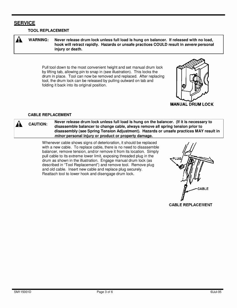
Pull tool down to the most convenient height and set manual drum lock by lifting tab, allowing pin to snap in (see illustration). This locks the drum in place. Tool can now be removed and replaced. After replacing tool, the drum lock can be released by pulling outward on tab and folding it back into its original position.
CABLE REPLACEMENT
MANUAL DRUM LOCK
CAUTION Never release drum lock unless full load is hung on the balancer. (It it is necessary to disassemble balancer to change cable, always remove all spring tension prior to disassembly (see Spring Tension Adjustment). Hazards or unsafe practices MAY result in minor personal injury or product or property damage.
Whenever cable shows signs of deterioration, it should be replaced with a new cable. To replace cable. there is no need to disassemble balancer, remove tension, and/or remove it from its location. Simply - pull cable to its extreme lower limit, exposing threaded plug in the drum as shown in the illustration. Engage manual drum lock (as PLUG
described in "Tool Replacement') and remove tool. Remove plug I and old cable. Insert new cable and replace plug securely. Reattach tool to lower hook and disengage drum lock.
CABLE
CABLE REPLACEMENT
SM11500ID Page 3of6 ©JuI-05
LOWER HOOK REPLACEMENT
CAUTION: Alter securing clamps (or sleeve), tape may be placed around cable end to prevent injury A on frayed strands. Hazards or unsafe practices MAY result in minor personal injury or product or property damage.
NOTE: Clamps are used for models xxxJaOl only; A swage-fitting sleeve should be used for all other models.
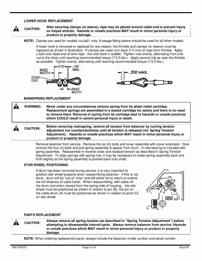
If lower hook is removed or replaced for any reason, the thimble and clamps (or sleeve) must be replaced as shown in illustration. If clamps are used, turn back 3 3/4 inch of rope from thimble. Apply u-bolt over dead end of wire rope - live end rests in saddle. Tighten nuts evenly, alternating from one nut to the other until reaching recommended torque (7.5 ft-lbs.). Apply second clip as near the thimble as possible. Tighten evenly, alternating until reaching recommended torque (7.5 ft-lbs.).
BASE _______ DEAD WIDTH— .312 MAX.
END
WIDTH
MAINSPRING REPLACEMENT
A WARNING: Never under any circumstances remove spring from its sheet metal cartridge. Replacement springs are assembled in a sealed cartridge for safety and there is no need to remove them. Removal of spring from its cartridge lead to hazards or unsafe practices which COULD result in severe personal injury or death.
CAUTIONS Before removing mainspring, remove all tension from balancer by turning tension adjustment nut counterclockwise until all tension is released (ref. Spring Tension Adjustment). Hazards or unsafe practices which MAY result in minor personal injury or product or property damage.
Remove balancer from service. Remove the six (6) bolts and cover assembly with cover extension. Now remove the four (4) bolts and pull spring assembly & spacer from drum. A new bearing is included with spring assembly. Reassemble in reverse order and readjust tension as described in Spring Tension Adjustment. To align springs with spring hub, it may be necessary to rotate spring assembly back and forth slightly as the spring assembly is pushed back onto shaft.
STAR WHEEL POSITIONING
If drum has been removed during service, it is very important to position star wheel properly when reassembling balancer. If this is not done, drum will be out-of- time" and will either fail to return or extend the full distance of cable travel. When reassembling, with cable off the drum and when viewed from the spring side of housing, the star wheel must be positioned as shown in relation to pin (B), the pin on the cable drum (A) must be positioned as shown in relation to point (C) on star wheel.
PARTS REPLACEMENT
CAUTION- Always remove all spring tension (as described in "Spring Tension Adjustment") before attempting to disassemble internal parts. Always remove balancer from service. Hazards or unsafe practices which MAY result in minor personal injury or product or property damage.
NOTE: When ordering replacement parts, always include the balancer model number and serial number.
SM1I5001D Page 4of6 ©JuI-05
All parts are replaceable in the field without special tools.
MAINTENANCE & INSPECTION
Periodic inspection of cable, lower hook, and upper swivel mount assembly (Kit A) is strongly recommended for safe operation. Bearings and guide rollers should also be inspected periodically to insure efficient operation. All bearings, springs, etc., are permanently lubricated at the factory and should require no further lubrication.
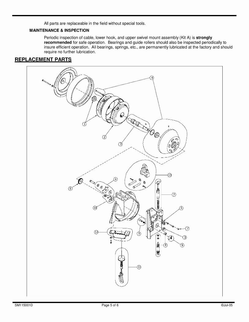
REPLACEMENT PARTS
- - - - - - - - - - - - - - -
- iz, in
SM1I5001O Page 5of6 ©JuI-05

Reference Number Part Number Qty. Description
3127600110 1 Outer Mainspring Assembly & Bearing (110,911 OKa) 3127600120 1 Outer Mainspring Assembly & Bearing (120,9120Ka) 3127600130 1 Outer Mainspring Assembly & Bearing (1 30,91 3OKa) 3127600140 1 Outer Mainspring Assembly & Bearing (1 40,91 4OKa) 3127600150 1 Outer Mainspring Assembly & Bearing (1 50,91 5OKa) 3127600160 1 Outer Mainspring Assembly & Bearing (160,9160Ka) 31276001 70 1 Outer Mainspring Assembly & Bearing (1 70Ka) 3127600190 1 Outer Mainspring Assembly & Bearing (190Ka) 3127600200 1 Outer Mainspring Assembly & Bearing (200Ka)
2 3127700110 1 Inner Mainspring Assembly (110,911 OKa) 3127700120 1 Inner Mainspring Assembly (1 20,91 2OKa) 3127700130 1 Inner Mainspring Assembly (1 30,91 3OKa) 3127700140 1 Inner Mainspring Assembly (140,9140Ka) 3127700150 1 Inner Mainspring Assembly (150,9150Ka) 3127700160 1 Inner Mainspring Assembly (160,9160Ka) 31277001 70 1 Inner Mainspring Assembly (1 70Ka) 3127700190 1 Inner Mainspring Assembly (190Ka) 3127700200 1 Inner Mainspring Assembly (200Ka)
3 SHFK 1 Shaft Kit 4 DRMK7 1 Drum Kit (2.1 m/7ft)
DRMK9 1 Drum Kit (2.7m/9ft) 5 3105800000 1 Gear, Main Shaft Worm 6 STAL7 1 Star Wheel Kit / Cable Length 7ft (standard)
STAL9 1 Star Wheel Kit / Cable Length 9ft (extended) 7 DSAKA 1 Drop Stop Actuator Kit for 110-1 30KA/91 1 0-2OKA
DSAKB 1 Drop Stop Actuator Kit for 140-1 6OKA/91 40-5OKA DSAKC 1 Drop Stop Actuator Kit for 1 70-200KA
8 WRMK 1 Worm Gear Kit 9 DLKK 1 Drum Lock Kit 10 DSLK 1 Drop Stop Lever Kit 11 CBALB7 1 Cable Assy Kit; Bullard Type (2.1 m/7ft)
CBALB9 1 Cable Assy Kit; Bullard Type (2.7m/9ft) CBALT7 1 Cable Assy Kit; Tool Clip Type (2.1 m/7ft) CBALT9 1 Cable Assy Kit; Tool Clip Type (2.7m/9ft)
12 CBGK 1 Cable guide assembly 13 UHKKB 1 Upper Hook Kit; Bullard Type
UHKKS 1 Uooer Hook Kit: Shackle Tvoe
SM1I5001O Page 6of6 ©JuI-05