(01.03.2018) Installation Instruction FISTUNE DAB/DAB+ ...
19
www.kufatec.de Kufatec GmbH & Co. KG • Dahlienstr. 15 • 23795 Bad Segeberg • e-mail: [email protected] Version 1.06 (01.03.2018) Installation Instruction FISTUNE DAB/DAB+ Integration Vehicles without DAB Tuner Vehicles with factory-installed DAB Tuner Article no. 40148 40148-1 BMW E-Serie CCC Mini Cooper R56
Transcript of (01.03.2018) Installation Instruction FISTUNE DAB/DAB+ ...

www.kufatec.de
Kufatec GmbH & Co. KG • Dahlienstr. 15 • 23795 Bad Segeberg • e-mail: [email protected]
Version 1.06
(01.03.2018)
Installation Instruction
FISTUNE DAB/DAB+ Integration
Vehicles without DAB Tuner
Vehicles with factory-installed DAB Tuner
Article no. 40148
40148-1
BMW E-Serie CCC
Mini Cooper R56

1
Contents
Disclaimer ................................................................................................................................................ 2
Copyright .................................................................................................................................................. 3
General advice ......................................................................................................................................... 3
Safety instructions .................................................................................................................................... 4
References of legal regulations for operation ........................................................................................... 4
Notes ........................................................................................................................................................ 5
Scope of delivery for 40148 - BMW ................................................................................................... 5
Scope of delivery for 40148-1 - BMW ................................................................................................... 5
Installation instructions 40148 - BMW .................................................................................................... 6
Installation instructions 40148-1 - BMW.................................................................................................. 11
Installation instructions 40148-1 - Mini Cooper 15

2
Disclaimer
Dear Buyer,
our cable harnesses are developed with the help of the circuit diagrams and wiring schemes of the particular vehicle producer and they are tested and adjusted to the original vehicle before the serial production. Therefore the integration into to the on-board electric and electronic system follows the information of the vehicle producers. Our installation instructions are consistent, in course of the necessary pre-understanding and the precision of the presentation in text and picture, with the staff usual in vehicle electrics / electronic and they have proven their value already hundredfold in practice.
If during the installation of our products drench occur difficulties, so we are any time ready to provide you support by phone or E-Mail. Additionally we offer you to use the installation in our workshop in Bad Segeberg.
The costs arising from the third parties assigned with the installation of our products, bears the Buyer. Only when it proves that there is a failure of our product we will compensate the evidenced costs of the assembly and the costs of the dismantling of the defective product, whereby we limit the cost reimbursement up to 110 EURO gross and we reserve our right to check the claimed defect in our workshop in Bad Segeberg. The costs of dispatch will be refunded in case of a justified claim.
We made the experience that each professional workshop which is equipped with a necessary diagnosis devices, diagnosis software and the circuit diagrams of the producer, can find the possible defects in our products within a short period of time, so the assembly and disassembly including failure diagnosis, can take place in maximum 60 minutes.
We also made the experience that many workshops are not able to cope with the producer’s circuit diagrams and cannot read the common wiring schemes, so for simplest installation labors several hours are calculated. You will understand that we neither take the risk to find a reliable workshop nor we finance the training for the workers of the workshop of your confidence.
The costs that arise from the acquisition of the missing parts or replace for defective parts from another suppliers, we reimburse to the amount of the costs which would have arisen in case of subsequent delivery (saved expenditure). In this case according to the legal warranty law there would be no reimbursement right of any kind, as long as no deadline was set for the supplementary performance or a deadline for supplementary performance has not expired.
So if you have any problems during the installation or operation of our products call us write us an E-Mail, send us the product or come to our workshop in Bad Segeberg with your vehicle. We are sure to find a solution for concern of every kind.
Kind regards
Your Kufatec GmbH & Co. KG Team

3
Copyright
Our assembly and operation manuals, assembling diagrams and additional documentation in text or picture form are protected by law.
Disclosure and distribution of this documentation through print or online media is permitted only after previous written acceptance from Kufatec GmbH & Co. KG.
General advice
While developing this product, your personal safety combined with the best operating service, modern design and an up-to-date production technique was especially taken into account.
Unfortunately, despite the utmost care injuries and/or damages might occur due to improper installation and/or use.
Therefore please read with great care and completely this operating manual and store it appropriately!
For your safety all our products pass through a 100% control check.
We reserve the right to carry out technical changes which serve the improvement at any time.
According to each article and purpose, it is sometimes necessary to check each country’s legal regulations before installing and starting the unit.
In case of guarantee claims, the device has to be sent back to the seller in the original packaging with the attached bill of purchase and detailed defect‘s description. Please pay attention to the manufacturer‘s return requirements (RMA). The legal warranty directions are valid.
The warranty claims as well as the operating permissions become invalid due to:
a) unauthorized changes to the device or accessories which have not been approved or carried out by the manufacturer or its partners
b) opening the device‘s frame
c) self-made repairs on the device
d) improper use / operation
e) brute force to the device (drop, willful damage, accident etc.)
During installation, please pay attention to all safety relevant and legal directions.
The device has only to be installed by trained personnel or similarly qualified people.
Please limit the failure search to ca. 0,5 hour for the mechanical resp. 1.0 hour for electric labors during the assembly or functioning problems.
To avoid unnecessary additional expenses please send immediately an inquiry to our technical support using the Kufatec form (http://www.kufatec.de/shop/de/infocenter/).
Please provide always the following information:
• chassis number
• part number of the add-on kit
• exact description of the problem
• already executed labor

4
Safety instructions
The installation can be executed only by trained qualified personnel. Before the installation disconnect the power supply. Therefore cut off the battery from the vehicle electric system, follow the manufacturer’s specification.
• Never use bolts, screws and other fastening elements from car’s safety devices or steering wheel, brakes because it may influence your driving safety and cause accidents.
• Connect the device only to a 12V vehicle voltage with chassis ground to the car body. This unit cannot be used in large trucks or other vehicles which use a DC 24 V battery wiring system voltage.
• Avoid to install the device in places where it could hinder the safe driving or functional efficiency of the other units installed in the vehicle.
• This unit is only for the use with the following vehicles and model line; Only connections described within this instruction manual are allowed or required to use for installation.
• For damage impact caused by faulty installation, unsuitable connections or assembling in inappropriate vehicle types or models Kufatec GmbH &Co.KG assumes no liability.
• We advise you that these units process data out of the MOST protocol from the vehicle. During the assembly of this unit we as supplier have access to a specific model and we as producer don’t know the overall system you work with.
• Especially in case of changes within the same model line and the same model year we don’t guarantee the usability of our products. In case of the usability of our products with the manufacturer’s changes Kufatec GmbH assumes no liability.
• Kufatec GmbH assumes no liability that the assembly of the unit described in this manual is approved according the warranty regulations of the single car manufacturers. Please check your manufacturer’s conditions and warranty before you begin the installation.
• Kufatec GmbH reserves the right to change the device specification without further notice.
• Errors and changes excepted.
References of legal regulations for operation
Use this unit in the intended domain only.
If you use the unit in a foreign domain, if the unit is not installed properly, or if the unit will be reconstructed the operating permit and warranty will expire.

5
Notes
Scope of delivery for 40148
- FISTUNE module - Conversion kit
Scope of delivery for 40148-1
- FISTUNE module - Conversion kit
Note:
Suitable for the following radio systems:
• CCC Professional
• CCC Business
• CCC Radio Professional
• Radio Professional 1 DIN
Note:
• No automatic channel search takes place, this has to be started manually via the iDrive or the radio.
• A repeated channel search is necessary only for the regional ensembles, when the vehicle position changes and herewith the regional ensembles also change.
• In case of over-regional ensembles the repeated channel search is not necessary.
Note:
No automatic switch-over from DAB to FM.
Note:
The installation instruction refers to the sample assembly in a BMW Z4 E89, 5 Series E60 and Mini Cooper R56, the assembly in a different vehicle can vary !

6
Installation Instructions 40148 - BMW
The following presentation shows the laying of the wires and the position of the single components as well:
Scheme
1 – FISTUNE module
2 – Mainunit
3 – Antenna
3
2
1
1,2
3

7
Take out the clipped interior blind and disconnect the plug connection on the rear side (fig. 1).
Fig. 1
Dismantle the radio control unit, for this purpose loosen the both screws. Take out the radio control unit and disconnect the plug connections on the rear side (fig. 2).
Fig. 2
Afterwards dismantle the main unit, for this purpose loosen the screws and take out the main unit (fig. 3).
Fig. 3

8
Disconnect the compact plug from the main unit (fig. 4) and take out the light conductor (fig. 5).
Fig. 4 Fig. 5
Braze the wire for the power supply of the FISTUNE module on the available wires for the power supply of the main unit, according to the wire imprint (fig. 6).
Red wire PIN 15 - Permanent positive
Brown wire PIN 12 - Ground
Fig. 6
9
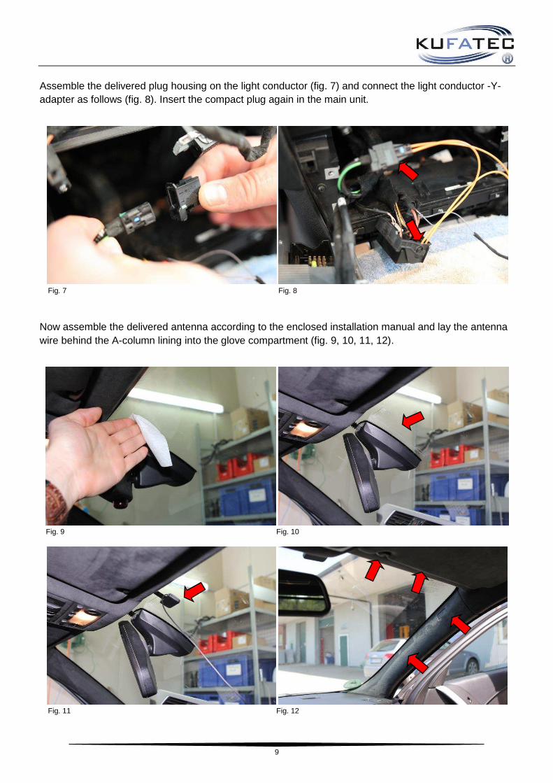
Assemble the delivered plug housing on the light conductor (fig. 7) and connect the light conductor -Y-adapter as follows (fig. 8). Insert the compact plug again in the main unit.
Fig. 7 Fig. 8
Now assemble the delivered antenna according to the enclosed installation manual and lay the antenna wire behind the A-column lining into the glove compartment (fig. 9, 10, 11, 12).
Fig. 9 Fig. 10
Fig. 11 Fig. 12

10
After a successful configuration please select menu point “Autostore“ (fig. 13) and confirm the selection. Following, confirm the function “Autostore“ (fig. 14) – the search starts, all found channels will be stored automatically.
Fig. 13 Fig. 14
To display DAB-text, select a channel with the iDrive Controler and confirm the selection. The menu below (fig. 15) will be displayed. Scroll down, select and confirm “Details“.
Fig. 15
Finally using workshop material assemble the FISTUNE module behind the glove compartment resp. dashboard and lay all the wires professionally and connect at the FISTUNE module. The reassembly takes place in a backward sequence.
Configuration:
▪Connect the antenna wire, as well as the optical fiber cable to the FISTUNE module
▪Don’t connect the plug for power yet!
▪Start the radio/navigation system and wait about 2 minutes until the system has started completely
▪Now connect the plug for power to the FISTUNE module
▪The FISTUNE module performs it’s self-configuration
▪ Start the channel search at the radio and check if the DAB+ signal is present

11
Installation Instructions 40148-1 - BMW
The following presentation shows the laying of the wires and the position of the single components as well:
Scheme
1 – FISTUNE module
1
1

12
Dismantle the trunk linings, for this remove the plastic clips (fig. 1, 2, 3, 4).
Fig. 1 Fig. 2
Fig. 3 Fig. 4
Dismantle the original holders with the DAB Tuner, for this purpose loosen the bolting and disconnect the plug connections. Besides remove the original DAB Tuner from the holder, for this loosen the bolting (fig. 5, 6).
Fig. 5 Fig. 6

13
Remove the light conductor from the original compact plug and pin out the wire for the power supply. Integrate the light conductor in the delivered compact plug and pin in the wires for the power supply (fig. 7, 8).
Fig. 7 Fig. 8
Remove the right antenna wire from the original antenna plug, for this loosen the colored locking and integrate the antenna wire in the delivered antenna plug (fig. 9, 10).
Fig. 9 Fig. 10
Permanant positive (blue/red wire) PIN 9
Ground (brown wire) PIN 8

14
Connect the changed plug connections to the FISTUNE module and fasten the module using workshop material (fig. 11).
Fig. 11
The assembly takes place in a backward sequence, afterwards carry out a channel search in the navigation unit (fig. 12).
Fig. 12

15
Installation Instructions 40148-1 – Mini Cooper
The following presentation shows the laying of the wires and the position of the single components as well:
Scheme
1 - FISTUNE module
1
1

16
Please remove the boot sill by loosening the three marked plastic clips, afterwards you can take out the boot sill trim by using an assembly lever (fig. 1 + 2).
Fig. 1 Fig. 2
Fold up the right rear seat forward, for this you have to fold up the locking lever (fig. 3). Separate the smaller lateral covering from the larger one, afterwards loosen the five marked plastic clips from the cloth covering. After this, you can remove the complete covering (fig. 4).
Fig. 3 Fig. 4
The DAB-tuner is positioned behind the disassembled lateral covering (fig. 5). Disassemble the covering by removing the three marked screws (1x cross-headed screw, 2x 10er nut). Take out the holder with the DAB-tuner and disconnect the present plugs (fig. 6).
Fig. 5 Fig. 6
17
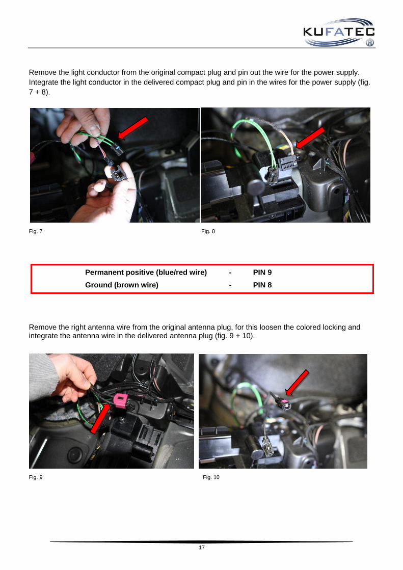
Remove the light conductor from the original compact plug and pin out the wire for the power supply. Integrate the light conductor in the delivered compact plug and pin in the wires for the power supply (fig. 7 + 8).
Fig. 7 Fig. 8
Remove the right antenna wire from the original antenna plug, for this loosen the colored locking and integrate the antenna wire in the delivered antenna plug (fig. 9 + 10).
Fig. 9 Fig. 10
Permanent positive (blue/red wire) - PIN 9
Ground (brown wire) - PIN 8

18
Connect the modified plug connections with the FISTUNE module, fix the module with appropriate factory material and with the uninstalled screws before and finally put it in the former installation position (fig. 11).
Fig. 11
The assembly occurs in reverse order, afterwards you have to start the station scan in the navigation program (fig. 12).
Fig. 12