


Languages
Pages
Legal

Stylus C58/C59 ME 2 Stylus C79/D78 Stylus C90/C91/C92/D92 Stylus T20/T20E/T23/T26/S20 Stylus T10/T11 ME 30 Stylus T21/T24/T27/S21
Inkjet Printer
S ANUAL
EpsonEpsonEpsonEpsonEpsonEpsonEpsonEpson
Color
ERVICE M
SEIJ06-003Confidential
Confidential
y any means, electronic, mechanical,
EIKO EPSON would greatly appreciate being
or the consequences thereof.
trademarks of their
Notice:All rights reserved. No part of this manual may be reproduced, stored in a retrieval system, or transmitted in any form or bphotocopying, recording, or otherwise, without the prior written permission of SEIKO EPSON CORPORATION.
The contents of this manual are subject to change without notice.
All effort have been made to ensure the accuracy of the contents of this manual. However, should any errors be detected, Sinformed of them.
The above not withstanding, SEIKO EPSON CORPORATION can assume no responsibility for any errors in this manual
EPSON is a registered trademark of SEIKO EPSON CORPORATION.
General Notice: Other product names used herein are for identification purpose only and may be trademarks or registeredrespective owners. EPSON disclaims any and all rights in those marks.
Copyright © 2009 SEIKO EPSON CORPORATION. IJP LP CS Quality Assurance Department

Confidential
PRECAUTIONSPrecautionary notations throughout the text are categorized relative to 1) personal injury and 2) damage to equipment.
DANGER Signals a precaution which, if ignored, could result in serious or fatal personal injury. Great caution should be exercised in performing procedures preceded by DANGER Headings.
WARNING Signals a precaution which, if ignored, could result in damage to equipment.
The precautionary measures itemized below should always be observed when performing repair/maintenance procedures.
DANGER1. ALWAYS DISCONNECT THE PRODUCT FROM THE POWER SOURCE AND PERIPHERAL DEVICES PERFORMING ANY MAINTENANCE OR REPAIR
PROCEDURES.
2. NO WORK SHOULD BE PERFORMED ON THE UNIT BY PERSONS UNFAMILIAR WITH BASIC SAFETY MEASURES AS DICTATED FOR ALL ELECTRONICS TECHNICIANS IN THEIR LINE OF WORK.
3. WHEN PERFORMING TESTING AS DICTATED WITHIN THIS MANUAL, DO NOT CONNECT THE UNIT TO A POWER SOURCE UNTIL INSTRUCTED TO DO SO. WHEN THE POWER SUPPLY CABLE MUST BE CONNECTED, USE EXTREME CAUTION IN WORKING ON POWER SUPPLY AND OTHER ELECTRONIC COMPONENTS.
4. WHEN DISASSEMBLING OR ASSEMBLING A PRODUCT, MAKE SURE TO WEAR GLOVES TO AVOID INJURY FROM METAL PARTS WITH SHARP EDGES.
WARNING1. REPAIRS ON EPSON PRODUCT SHOULD BE PERFORMED ONLY BY AN EPSON CERTIFIED REPAIR TECHNICIAN.
2. MAKE CERTAIN THAT THE SOURCE VOLTAGE IS THE SAME AS THE RATED VOLTAGE, LISTED ON THE SERIAL NUMBER/RATING PLATE. IF THE EPSON PRODUCT HAS A PRIMARY AC RATING DIFFERENT FROM AVAILABLE POWER SOURCE, DO NOT CONNECT IT TO THE POWER SOURCE.
3. ALWAYS VERIFY THAT THE EPSON PRODUCT HAS BEEN DISCONNECTED FROM THE POWER SOURCE BEFORE REMOVING OR REPLACING PRINTED CIRCUIT BOARDS AND/OR INDIVIDUAL CHIPS.
4. IN ORDER TO PROTECT SENSITIVE MICROPROCESSORS AND CIRCUITRY, USE STATIC DISCHARGE EQUIPMENT, SUCH AS ANTI-STATIC WRIST STRAPS, WHEN ACCESSING INTERNAL COMPONENTS.
5. REPLACE MALFUNCTIONING COMPONENTS ONLY WITH THOSE COMPONENTS BY THE MANUFACTURE; INTRODUCTION OF SECOND-SOURCE ICs OR OTHER NON-APPROVED COMPONENTS MAY DAMAGE THE PRODUCT AND VOID ANY APPLICABLE EPSON WARRANTY.
6. WHEN USING COMPRESSED AIR PRODUCTS; SUCH AS AIR DUSTER, FOR CLEANING DURING REPAIR AND MAINTENANCE, THE USE OF SUCH PRODUCTS CONTAINING FLAMMABLE GAS IS PROHIBITED.

Confidential
Th the printer. Th to the precautions on the preceding page.
ThCH
CH
CH
CH
CH
CH
AP
Used in this Manual
hout this manual either to provide additional r to warn of possible danger present during a of all symbols when they are used, and always read
ING messages.
ting or maintenance procedure, practice or condition observed, could result in injury.
ting or maintenance procedure, practice, or condition observed, could result in damage to, or destruction of,
perating or maintenance procedure, practice or ecessary to accomplish a task efficiently. It may also l information that is related to a specific subject, or esults achieved through a previous action.
ting or maintenance procedure, practice or condition o maintain the product’s quality.
rticular task must be carried out according to a certain ssembly and before re-assembly, otherwise the ponents in question may be adversely affected.
About This Manualis manual describes basic functions, theory of electrical and mechanical operations, maintenance, and repair procedures of e instructions and procedures included herein are intended for experienced repair technicians, and attention should be given
Manual Configuration
is manual consists of six chapters and Appendix.APTER 1.PRODUCT DESCRIPTIONS
Provides a general overview and specifications of the product.APTER 2.OPERATING PRINCIPLES
Describes the theory of electrical and mechanical operations of the product.
APTER 3.TROUBLESHOOTING Describes the step-by-step procedures for the troubleshooting.
APTER 4.DISASSEMBLY / ASSEMBLY Describes the step-by-step procedures for disassembling and assembling the product.
APTER 5.ADJUSTMENT Provides Epson-approved methods for adjustment.
APTER 6.MAINTENANCE Provides preventive maintenance procedures and the list of Epson-approved lubricants and adhesives required for servicing the product.
PENDIX Provides the following additional information for reference:• Exploded Diagram
Symbols
Various symbols are used througinformation on a specific topic oprocedure or an action. Be awareNOTE, CAUTION, and WARN
Indicates an operathat, if not strictly
Indicates an operathat, if not strictlyequipment.
May indicate an ocondition that is nprovide additionacomment on the r
Indicates an operathat is necessary t
Indicates that a pastandard after disaquality of the com
� � � � � � �
� � � � �
� � � �
� � � �
� � � � � �
� � � � �

Confidential
zle from increasing viscosity when the printer is in
added.
Revision StatusRevision Date of Issue Description
A August 7, 2006 First Release
B December 1, 2006 [Chapter 4]• “4.3.1 Upper Housing (p38)”
Note when replacing the Base Frame is added to the reassembly procedure.[Chapter 7]• “7.1 Exploded Diagram / Parts List (p85)” are updated.
C May 1, 2007 [All chapters]• The model name; EPSON Stylus C90/C91/C92/D92 are added.[Chapter 1]• “1.2.3 Ink Cartridge (p14)” is updated.[Chapter 2]• “ The Capping mechanism covers the printhead with the cap to prevent the noz
stand-by state or when the printer is off. (p25)” is updated.[Chapter 4]• “4.5.6 Ink System removal (p51)”
Caution during inserting the Ink Tube into the connector is added.• “4.5.8 EJ Frame Assy/EJ Roller (p54)”
Reassembly procedure of the Grounding Spring, Frame is added.[Chapter 5]• “5.2.1 Head angular adjustment (p75)”
Print samples made by the adjustment program for Stylus C90/C91/C92/D92 is[Chapter 6]• “6.1.3 Lubrication (p81)”
Lubrication point for Stylus C90/C91/C92/D92 is added.[Chapter 7]• “7.1 Exploded Diagram / Parts List (p85)”
Exploded Diagrams for Stylus C90/C91/C92/D92 are added.• “7.3 Circuit Diagrams (p96)”
Circuit diagram of Stylus C90/C91/C92/D92; C683 Main is added.

Confidential
Revision Date of Issue Description
D May 16, 2008 [All chapters]The model name; Stylus T20/T20E/T23/T26/S20/T10/T11/Me 30 are added.[Chapter 1]• “1.1 Features (p10)” is updated.• “1.2.1 Paper Support (p12)” is updated.• “1.2.3 Ink Cartridge (p14)” is updated.• “1.3.1 USB Interface (p16)” is updated.[Chapter 2]• 2.3 Electrical Circuit Operating Principles is deleted.[Chapter 4]• “4.1.6 Procedural Differences between the Models (p35)” is updated.• “4.2 Disassembly Procedures (p37)” is updated.• “4.5.5 CR Unit/Timing Belt (p48)”
Reassembly procedure of the Installing Head FFC is added.[Chapter 7]• Exploded Diagram / Parts List is changed to reference to SPI.• Circuit Diagrams is deleted.
E May 7, 2009 [All chapters]The model name; Epson Stylus T21/T24/T27/S21 are added.[Chapter 1]• “1.1 Features (p10)” is updated.• “ Print speed & printable width (p11)” is updated.• “1.2.1 Paper Support (p12)” is updated.• “1.2.2 Printable Area Size and Margins (p13)” is updated.• “1.2.3 Ink Cartridge (p14)” is updated.• “1.2.4 Black Ink Save Mode (p15)” is updated.• “1.3.1 USB Interface (p16)” is updated.• “1.4.1 Electrical Specifications (p17)” is updated.• “1.4.2 Acoustic Noise (p17)” is updated.• “1.4.3 Safety Approvals (p17)” is updated.• “1.4.5 Environmental Performance (p18)” is revised.• “1.4.6 Durability (p18)” is revised.[Chapter 2]• “2.3 Power-On Sequence (p26)” is added.

Epson Stylus C58/C59/ME 2/C79/D78/C90/C91/C92/D92/T20/T20E/T23/T26/S20/T10/T11/ME 30/T21/T24/T27/S21 Revision E
7Confidential
Ch1.11.2
1.3
1.4
1.5
Ch2.12.2
2.3
TING.......................................................................... 28.......................................................................... 28.......................................................................... 28or Indications.................................................... 29 Sensors ........................................................... 30
ASSEMBLY.......................................................................... 32.......................................................................... 32.......................................................................... 33.......................................................................... 33......................................................................... 34.......................................................................... 34etween the Models........................................... 35.......................................................................... 37.......................................................................... 38.......................................................................... 38.......................................................................... 40.......................................................................... 40
Contents apter 1 PRODUCT DESCRIPTION Features............................................................................................................... 10 Printer Specifications.......................................................................................... 11
1.2.1 Paper Support .......................................................................................... 121.2.2 Printable Area Size and Margins ............................................................. 131.2.3 Ink Cartridge............................................................................................ 141.2.4 Black Ink Save Mode .............................................................................. 15
Interface.............................................................................................................. 161.3.1 USB Interface .......................................................................................... 16
General Specifications........................................................................................ 171.4.1 Electrical Specifications .......................................................................... 171.4.2 Acoustic Noise......................................................................................... 171.4.3 Safety Approvals ..................................................................................... 171.4.4 CE Marking ............................................................................................. 171.4.5 Environmental Performance .................................................................... 181.4.6 Durability................................................................................................. 18
Control Panel ...................................................................................................... 191.5.1 Buttons..................................................................................................... 191.5.2 Indicators ................................................................................................. 191.5.3 Errors and Panel Status............................................................................ 201.5.4 Printer Initialization................................................................................. 20
apter 2 OPERATING PRINCIPLES Overview ............................................................................................................ 22 Printer Mechanism.............................................................................................. 22
2.2.1 Printhead Specifications .......................................................................... 232.2.2 Carriage Mechanism................................................................................ 232.2.3 Paper Feeding Mechanism ...................................................................... 242.2.4 Ink System Mechanism ........................................................................... 25
Power-On Sequence ........................................................................................... 26
Chapter 3 TROUBLESHOO3.1 Overview ..................................
3.1.1 Specified Tools..............3.1.2 Preliminary Checks .......
3.2 Troubleshooting With LED Err3.3 Troubleshooting for Motors and
Chapter 4 DISASSEMBLY/4.1 Overview ..................................
4.1.1 Precautions ....................4.1.2 Tools ..............................4.1.3 Screws ...........................4.1.4 Work Completion Check4.1.5 Caution After Repair .....4.1.6 Procedural Differences b
4.2 Disassembly Procedures...........4.3 Removing Housing...................
4.3.1 Upper Housing ..............4.4 Removing Board.......................
4.4.1 Main Board....................
Epson Stylus C58/C59/ME 2/C79/D78/C90/C91/C92/D92/T20/T20E/T23/T26/S20/T10/T11/ME 30/T21/T24/T27/S21 Revision E
8Confidential
4.5
4.6
4.7
Ch5.1
5.2
Ch6.1
.......................................................................... 85
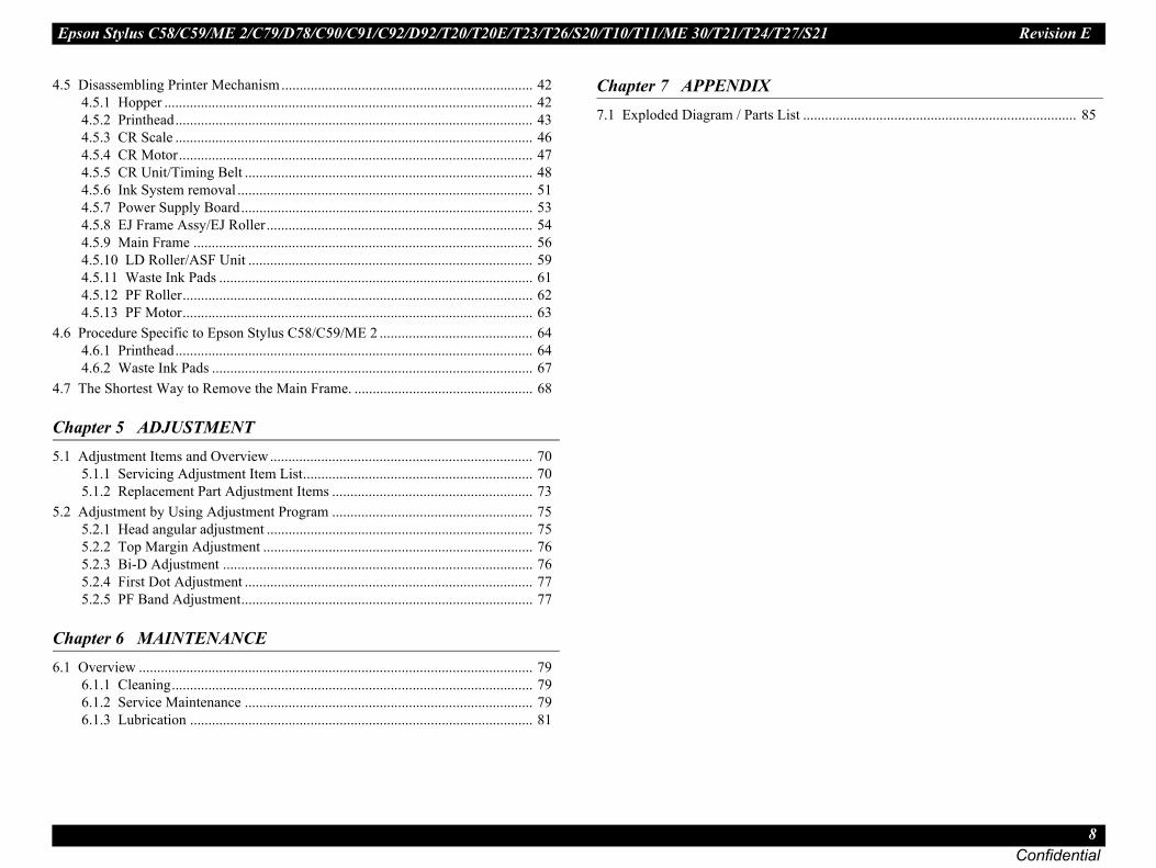
Disassembling Printer Mechanism..................................................................... 424.5.1 Hopper ..................................................................................................... 424.5.2 Printhead.................................................................................................. 434.5.3 CR Scale .................................................................................................. 464.5.4 CR Motor................................................................................................. 474.5.5 CR Unit/Timing Belt ............................................................................... 484.5.6 Ink System removal ................................................................................. 514.5.7 Power Supply Board................................................................................ 534.5.8 EJ Frame Assy/EJ Roller......................................................................... 544.5.9 Main Frame ............................................................................................. 564.5.10 LD Roller/ASF Unit .............................................................................. 594.5.11 Waste Ink Pads ...................................................................................... 614.5.12 PF Roller................................................................................................ 624.5.13 PF Motor................................................................................................ 63
Procedure Specific to Epson Stylus C58/C59/ME 2 .......................................... 644.6.1 Printhead.................................................................................................. 644.6.2 Waste Ink Pads ........................................................................................ 67
The Shortest Way to Remove the Main Frame. ................................................. 68
apter 5 ADJUSTMENT Adjustment Items and Overview........................................................................ 70
5.1.1 Servicing Adjustment Item List............................................................... 705.1.2 Replacement Part Adjustment Items ....................................................... 73
Adjustment by Using Adjustment Program ....................................................... 755.2.1 Head angular adjustment ......................................................................... 755.2.2 Top Margin Adjustment .......................................................................... 765.2.3 Bi-D Adjustment ..................................................................................... 765.2.4 First Dot Adjustment ............................................................................... 775.2.5 PF Band Adjustment................................................................................ 77
apter 6 MAINTENANCE Overview ............................................................................................................ 79
6.1.1 Cleaning................................................................................................... 796.1.2 Service Maintenance ............................................................................... 796.1.3 Lubrication .............................................................................................. 81
Chapter 7 APPENDIX7.1 Exploded Diagram / Parts List .

C H A P T E R
Confidential
1PR CT DESCRIPTION
ODU
Epson Stylus C58/C59/ME 2/C79/D78/C90/C91/C92/D92/T20/T20E/T23/T26/S20/T10/T11/ME 30/T21/T24/T27/S21 Revision E
P 10Confidential
1.MaC9
ThC9
Th
support closed
ridges
. External View
RODUCT DESCRIPTION Features
1 Featuresin features of Epson Stylus C58/C59/ME 2 and Epson Stylus C79/D78/C90/1/C92/D92/T20/T20E/T23/T26/S20/T10/T11/Epson ME 30/T21/T24/T27/S21
High quality color printing
Maximum print resolution: 5760 (H) x 1440 (V) dpi
4-color printing (Yellow, Magenta, Cyan, and Black)
Separate ink cartridges for each color
Build-in ASF (Auto Sheet Feeder)
Holds 80 cut sheets (24 lb, 90 g/m2)
Holds 20 special media (EPSON Premium Glossy Photo Paper, L (3R) size)
USB 1.1 compatible
Windows/Macintosh supported
Borderless printing
e difference between the Epson Stylus C58/C59/ME 2, Epson Stylus C79/D78/0/C91/C92/D92/T20/T20E/T23/T26/S20/T10/T11/ME 30/T21/T24/T27/S21
e main difference is the ink type as shown in the table below.
Dimension
With the output tray and paperWidth: 435 mm (17.1 inches)Depth: 219 mm (8.6 inches) Height: 165 mm (6.5 inches)
Maximum dimension Width: 435 mm (17.1 inches)Depth: 418 mm (16.5 inches)Height: 289 mm (11.4 inches)
Weight 2.8 kg (6.2 lb) without ink cart
Figure 1-1
Table 1-1. Difference between the Models
Model Ink Type
Epson Stylus C58/C59/ME 2 Dye-based ink which has a good distinction of color
Epson Stylus C79/D78/C90/C91/C92/D92/T20/T20E/T23/T26/S20/T10/T11/ME 30/T21/T24/T27/S21
Pigment-based ink that provides the water, light and ozone resistant
Epson Stylus C58/C59/ME 2/C79/D78/C90/C91/C92/D92/T20/T20E/T23/T26/S20/T10/T11/ME 30/T21/T24/T27/S21 Revision E
P 11Confidential
1. E WIDTH
Pr
N
Pr
Pr
Co
In
In
Pa
Pa
Pa
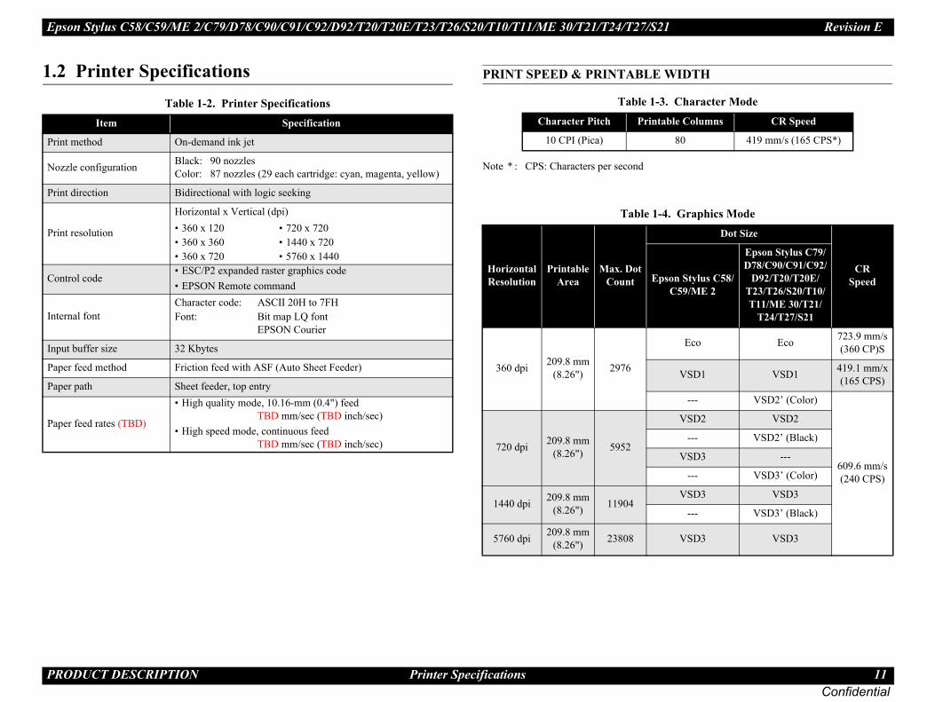
-3. Character Modentable Columns CR Speed
80 419 mm/s (165 CPS*)
1-4. Graphics Mode
Dot Size
CRSpeedEpson Stylus C58/
C59/ME 2
Epson Stylus C79/D78/C90/C91/C92/
D92/T20/T20E/T23/T26/S20/T10/T11/ME 30/T21/
T24/T27/S21
Eco Eco 723.9 mm/s(360 CP)S
VSD1 VSD1 419.1 mm/x(165 CPS)
--- VSD2’ (Color)
609.6 mm/s(240 CPS)
VSD2 VSD2
--- VSD2’ (Black)
VSD3 ---
--- VSD3’ (Color)
VSD3 VSD3
--- VSD3’ (Black)
VSD3 VSD3
RODUCT DESCRIPTION Printer Specifications
2 Printer Specifications PRINT SPEED & PRINTABL
Note * : CPS: Characters per second
Table 1-2. Printer SpecificationsItem Specification
int method On-demand ink jet
ozzle configuration Black: 90 nozzles Color: 87 nozzles (29 each cartridge: cyan, magenta, yellow)
int direction Bidirectional with logic seeking
int resolution
Horizontal x Vertical (dpi)• 360 x 120 • 720 x 720• 360 x 360 • 1440 x 720• 360 x 720 • 5760 x 1440
ntrol code• ESC/P2 expanded raster graphics code• EPSON Remote command
ternal fontCharacter code: ASCII 20H to 7FHFont: Bit map LQ font
EPSON Courier
put buffer size 32 Kbytes
per feed method Friction feed with ASF (Auto Sheet Feeder)
per path Sheet feeder, top entry
per feed rates (TBD)
• High quality mode, 10.16-mm (0.4") feed TBD mm/sec (TBD inch/sec)
• High speed mode, continuous feed TBD mm/sec (TBD inch/sec)
Table 1Character Pitch Pri
10 CPI (Pica)
Table
Horizontal Resolution
Printable Area
Max. DotCount
360 dpi 209.8 mm(8.26") 2976
720 dpi 209.8 mm(8.26") 5952
1440 dpi 209.8 mm(8.26") 11904
5760 dpi 209.8 mm(8.26") 23808

Epson Stylus C58/C59/ME 2/C79/D78/C90/C91/C92/D92/T20/T20E/T23/T26/S20/T10/T11/ME 30/T21/T24/T27/S21 Revision E
P 12Confidential
1.FoSu
e Table 1-6, “Paper Width and Length,” on page 13.
s T20/T20E/T23/T26/S20/T10/T11/ME30.d only by Epson Stylus T20/T20E/T23/T26/S20/T10/
T20/T20E/T23/T26/S20/T10/T11/ME30/T21/T24/
s T21/T24/T27/S21.nly for Epson Stylus T21/T24/T27/S21.
s T20/T20E/T23/T26/S20/T10/T11/ME30.
PlRe
En(B
EPSO
N sp
ecia
l pap
er
A4*2 0.12 102 g/m2 (27 lb.)
Letter*3
0.25 258 g/m2 (68 lb.)A4*1
5" x 7"*1
4" x 6"*1
AI)
Letter*3
0.30 290 g/m2 (77 lb.)
A4*3
8" x 10"*3
5" x 7"*1
4" x 6"*1
L (3R)*1*4
A4*6
0.24 190 g/m2 (51 lb.)5" x 7"*6
4" x 6"*6
paper is not wrinkled, fluffed, torn, or folded. must be 5 mm or below.o an envelope, be sure that the flap is on the lded.esive envelopes.envelopes and cellophane window envelopes.
5. Paper Support
Paper Size Thickness(mm) Weight
RODUCT DESCRIPTION Printer Specifications
2.1 Paper Supportllowing table shows the paper type and sizes supported by the printer. pported paper type and sizes vary depending on the markets.
Note 1: For paper width and length, seNote *1 : Borderless printing supported.
*2 : Supported only by Epson Stylu*3 : Borderless printing is supporte
T11/ME30/T21/T24/T27/S21.*4 : Not supported by Epson Stylus
T27/S21.*5 : Supported only by Epson Stylu*6 : Borderless printing supported o*7 : Supported only by Epson Stylu
Table 1-5. Paper Support
Item Paper Size Thickness(mm) Weight
ain papercycled paper
Letter
0.08-0.11 64-90 g/m2
(17-24 lb.)
LegalHalf Letter
A4A5A6B5
User defined
velope ond paper, Air mail, PPC)
No.10N/A 45-75g/m2
(12-20 lb.)DLC6
Premium Ink Jet Plain Paper A4 0.11 80 g/m2 (21 lb.)
Premium Bright White PaperA4*7
0.11 90 g/m2 (24 lb.)Letter*5
Bright White Ink Jet Paper A4 0.13 92.5 g/m2 (25 lb.)
Premium Photo Paper Glossy (EAI)Premium Glossy Photo Paper (Other)
Letter*3
0.27 255 g/m2 (68 lb.)
A4*1
8" x 10"*3
5" x 7"*1
4" x 6"*1
16:9 wide*1
L (3R)*1*4
Premium Photo Paper Semi-Gloss (EAI) Premium Semigloss Photo Paper (Other)
Letter*3
0.27 250 g/m2 (66 lb.)A4*1
4" x 6"*1
Premium Presentation Paper Matte (EAI) Matte Paper-Heavyweight (Other)
Letter*3
0.23 167 g/m2 (45 lb.)A4*1
8" x 10"*2*6
EPSO
N sp
ecia
l pap
er
Presentation Paper Matte (EAI) Photo Quality Inkjet Paper (Other)
Photo Paper Glossy (EAI) Glossy Photo Paper (EUR, Asia)
Ultra Premium Photo Paper Glossy (EUltra Glossy Photo Paper (Other)
Photo Paper (Others)
� � � � �Make sure that theThe curve of paperWhen printing ontlong edge and is foDo not use the adhDo not use double
Table 1-
Item

Epson Stylus C58/C59/ME 2/C79/D78/C90/C91/C92/D92/T20/T20E/T23/T26/S20/T10/T11/ME 30/T21/T24/T27/S21 Revision E
P 13Confidential
PA and Marginsr the printable area size and margins.
by enlarging the image size wider than the paper size as idth protruding from the paper size is shown below.
Guaranteed Print AreaA B-L B-R C D
3 mm (0.12")
3 mm (0.12")
3 mm (0.12")
12.5 mm (4.92")
20 mm (7.87")
3 mm (0.12")
3 mm (0.12")
3 mm (0.12")
3 mm (0.12") -
3 mm (0.12")
5 mm (0.2")
5 mm (0.2") - 20 mm
(7.87")
. Borderless PrintingBottom Left/Right
2") 4.02 mm (0.16") 2.54 mm (0.1")
1") 3.60 mm (0.14") 2.54 mm (0.1")
R-B
C
B-R
B-L
DBorderless printing*
Envelope
RODUCT DESCRIPTION Printer Specifications
PER WIDTH AND LENGTH 1.2.2 Printable Area SizeRefer to the table and figure below fo
Note : This is minimum margin.
Note * : Borderless printing is carried outshown in the figure. The image w
Table 1-6. Paper Width and LengthPaper Size Width Length
Cut
shee
t
A4 210 mm (8.3") 297 mm (11.7")
A5 148 mm (5.8") 210 mm (8.3")
A6 148 mm (5.8") 210 mm (8.3")
B5 182 mm (7.2") 257 mm (10.1")
Letter 215.9 mm (8.5") 279.4 mm (11")
Legal 215.9 mm (8.5") 355.6 mm (14")
Half Letter 139.7 mm (5.5") 215.9 mm (8.5")
8" x 10" 203.2 mm 254 mm
5" x 7" 127 mm 178 mm
4" x 7.11" 101.6 mm 180.6 mm
4" x 6" 101.6 mm 152.4 mm
L (3R) 89 mm (3.5") 127 mm (5")
User defined 50.8-329 mm(2-12.6")
127-1117.6 mm(5-44")
Enve
lope No.10 104.8 mm (4.125") 241.3 mm (9.5")
DL 110 mm 220 mm
C6 114 mm 162 mm
Table 1-7.
C58/C59/ME 2/C79/D78/C90/C91/C92/D92/T20/T20E/T23/T26/S20/T10/T11/ME 30
Any size/Envelope
T21/T24/T27/S21Any size
Envelope
Table 1-8Paper Size Top
A4, Letter, 8" x 10", 5" x 7", 4" x 7.11" 2.96 mm (0.1
4" x 6", L (3R) 2.82 mm (0.1
A
L-B
ACut sheet
Epson Stylus C58/C59/ME 2/C79/D78/C90/C91/C92/D92/T20/T20E/T23/T26/S20/T10/T11/ME 30/T21/T24/T27/S21 Revision E
P 14Confidential
1.
No
0/T20E/T23/T26/S20/T21/T24/T27/S21CISMEA Euro Asia
T0921NT0711T0891
T0731NT0911N
T0922NT0712T0892
T0732NT0912N
T0923NT0713T0893
T0733NT0913N
T0924NT0714T0894
T0734NT0914N
Epson Stylus T10/T11ESP/EKL
T0731N, T0911NT0732N, T0912NT0733N, T0913NT0734N, T0914N
-14. Epson ME 30ECC
T1091T1092T1093T1094
RODUCT DESCRIPTION Printer Specifications
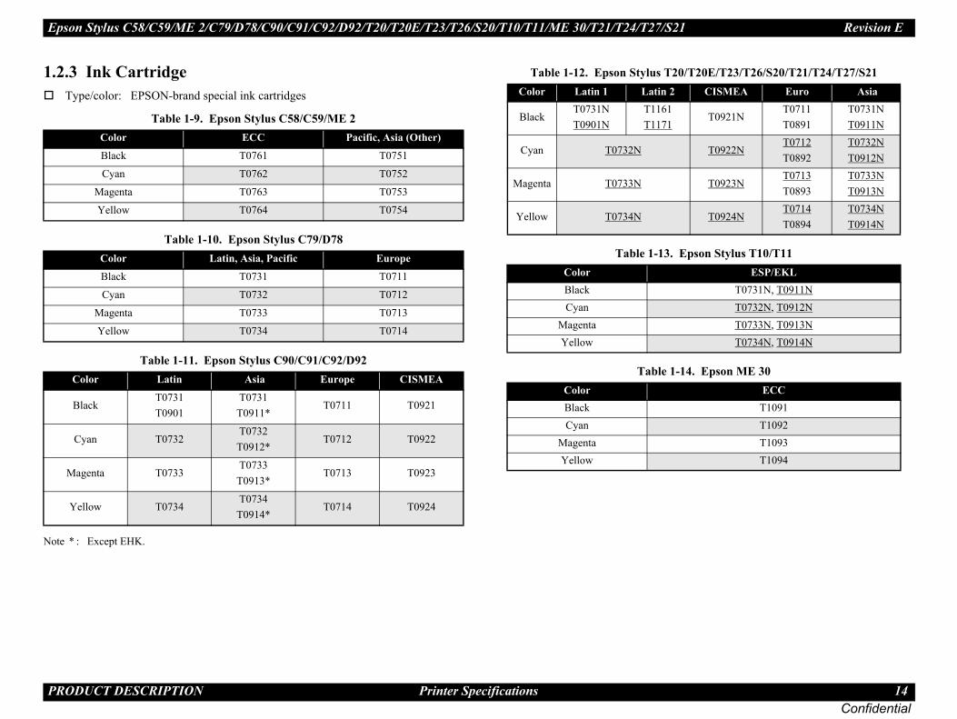
2.3 Ink CartridgeType/color: EPSON-brand special ink cartridges
te * : Except EHK.
Table 1-9. Epson Stylus C58/C59/ME 2Color ECC Pacific, Asia (Other)
Black T0761 T0751
Cyan T0762 T0752
Magenta T0763 T0753
Yellow T0764 T0754
Table 1-10. Epson Stylus C79/D78Color Latin, Asia, Pacific Europe
Black T0731 T0711
Cyan T0732 T0712
Magenta T0733 T0713
Yellow T0734 T0714
Table 1-11. Epson Stylus C90/C91/C92/D92Color Latin Asia Europe CISMEA
BlackT0731T0901
T0731T0911*
T0711 T0921
Cyan T0732T0732
T0912*T0712 T0922
Magenta T0733T0733
T0913*T0713 T0923
Yellow T0734T0734
T0914*T0714 T0924
Table 1-12. Epson Stylus T2Color Latin 1 Latin 2
BlackT0731NT0901N
T1161T1171
Cyan T0732N
Magenta T0733N
Yellow T0734N
Table 1-13. ColorBlackCyan
MagentaYellow
Table 1ColorBlackCyan
MagentaYellow

Epson Stylus C58/C59/ME 2/C79/D78/C90/C91/C92/D92/T20/T20E/T23/T26/S20/T10/T11/ME 30/T21/T24/T27/S21 Revision E
P 15Confidential
et images with color ink only when the remain-de can be selected when the remaining amount as of the images are printed with a mixture of
, 2000, XP, XP x64, Vista 10.3.9, 10.4.x, 10.5.x
tosh OS are for Epson Stylus T21/T24/
xt Mode (360 dpi)
plication.
rinting mode and the amount of remaining ink, the conditions described below are all met.
orts black ink save mode.nk is less than 5%, or the status of the black ink
color ink is more than 10%, or the status of all ”.
Black Ink Save Mode
W
W
�
Starts printing in black ink save mode.Starts printing in a normal manner.Starts printing in a normal manner. This window will not be displayed again until the black ink cartridge is replaced.
RODUCT DESCRIPTION Printer Specifications
Shelf life: Two years from production date (if unopened), six months after opening package.
Storage Temperature
Dimension
Epson Stylus C58/C59/ME 2
12.7 mm (W) x 43 mm (D) x 47 mm (H)
Epson Stylus C79/D78/C90/C91/C92/D92/T20/T20E/T23/T26/S20/T10/T11/ME30/T21/T24/T27/S21
12.7 mm (W) x 68 mm (D) x 47 mm (H)
1.2.4 Black Ink Save ModBlack ink save mode allows you to prining amount of black ink is low. This moof color ink is sufficient since black areother colors.
Supported OS: Windows 98, MEMacintosh OS X
NOTE: Windows Vista and MacinT27/S21 only.
Printing mode: Plain Paper & Te
Operating procedure
1. User carries out printing from an ap
2. The printer driver checks both the pand displays the specific window if
• Selected printing mode supp• Remaining amount of black i
is “ink low”.• Remaining amount of all the
the color ink is NOT “ink low
Flowchart 1-1.
Table 1-15. Storage TemperatureSituation Storage Temperature Limit
hen stored in individual boxes -30 oC to 40 oC(-22oF to 104oF)
1 month max. at 40 oC (104oF)hen installed in main unit
-20 oC to 40 oC(-4oF to 104oF)
� � � �The ink cartridge cannot be refilled.The ink cartridge that passes the expiration date should not be used.The ink in the ink cartridge freezes at -16 °C (3.2 oF). Ink thaws and is usable after approximately three hours at 25 °C (77oF).
Epson Stylus C58/C59/ME 2/C79/D78/C90/C91/C92/D92/T20/T20E/T23/T26/S20/T10/T11/ME 30/T21/T24/T27/S21 Revision E
P 16Confidential
1.EpT2int
1.
NO
@MCMMCLD[F
RODUCT DESCRIPTION Interface
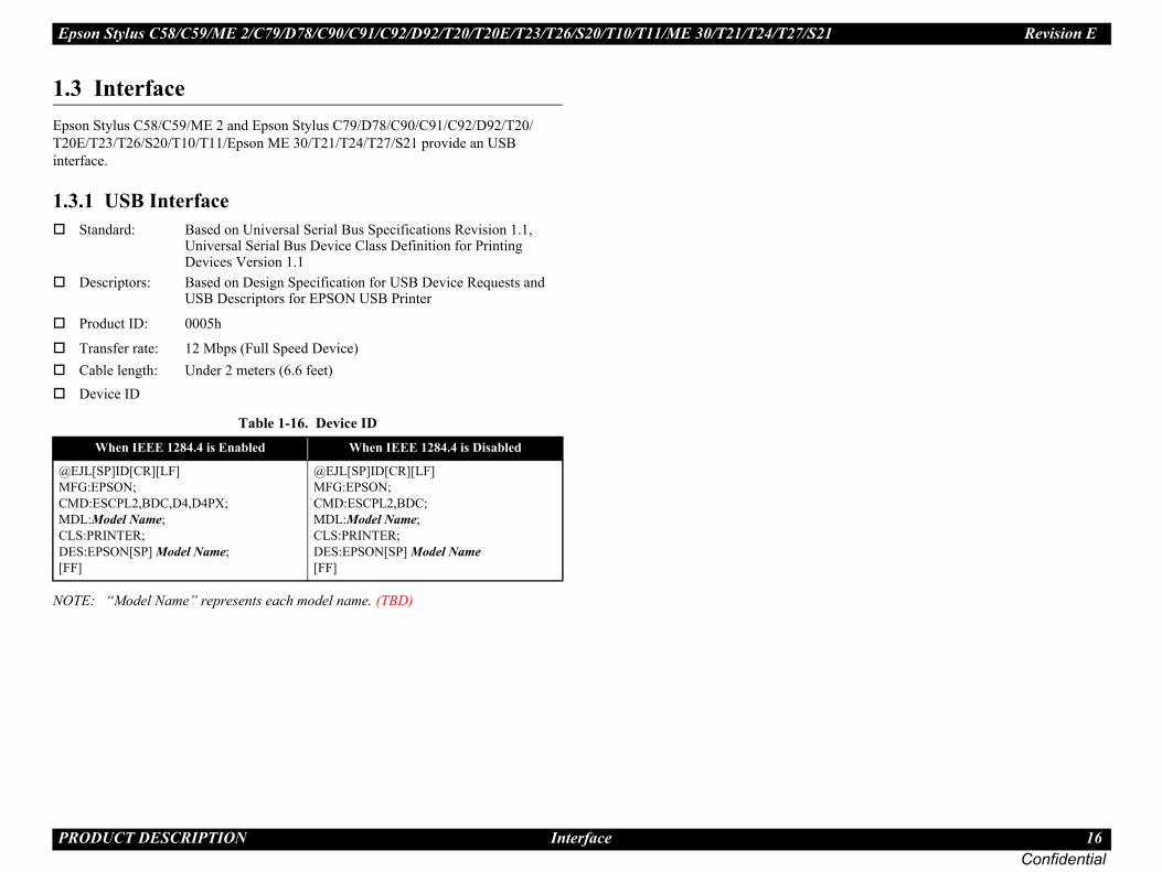
3 Interfaceson Stylus C58/C59/ME 2 and Epson Stylus C79/D78/C90/C91/C92/D92/T20/0E/T23/T26/S20/T10/T11/Epson ME 30/T21/T24/T27/S21 provide an USB erface.
3.1 USB InterfaceStandard: Based on Universal Serial Bus Specifications Revision 1.1,
Universal Serial Bus Device Class Definition for Printing Devices Version 1.1
Descriptors: Based on Design Specification for USB Device Requests and USB Descriptors for EPSON USB Printer
Product ID: 0005h
Transfer rate: 12 Mbps (Full Speed Device)Cable length: Under 2 meters (6.6 feet)Device ID
TE: “Model Name” represents each model name. (TBD)
Table 1-16. Device IDWhen IEEE 1284.4 is Enabled When IEEE 1284.4 is Disabled
EJL[SP]ID[CR][LF] FG:EPSON;
D:ESCPL2,BDC,D4,D4PX; DL:Model Name; S:PRINTER;
ES:EPSON[SP] Model Name; F]
@EJL[SP]ID[CR][LF] MFG:EPSON; CMD:ESCPL2,BDC; MDL:Model Name; CLS:PRINTER; DES:EPSON[SP] Model Name [FF]

Epson Stylus C58/C59/ME 2/C79/D78/C90/C91/C92/D92/T20/T20E/T23/T26/S20/T10/T11/ME 30/T21/T24/T27/S21 Revision E
P 17Confidential
1.
1.
No
1.
No
Safety Approvals
21
C: EN60950EN5502 Class B, EN61000-3-2, EN61000-3-3, EN55024
R
In
R
R
In
Po
EpT2
Ep
rsion 220-240 V version
EN 60950
GOST-R (IEC60950, CISPR22)*
* K60950-1*
0)* IEC60950-1*
class B EN 55022(CISPR Pub.22) class B
AS/NZS CISPR22 class B
KN22 Class B*
KN61000-4-2/-3/-4/-5/-6/-11*
RODUCT DESCRIPTION General Specifications
4 General Specifications
4.1 Electrical SpecificationsPrimary power input
te 1: This product complies with the “Energy Star” standards.2: If the printer is not operated for more than five minutes, the standby function reduces
the current to the motor to conserve power.
Dielectric strength
AC1000 Vrms for 1 min. or AC1200 Vrms for 1 sec. (100-120V version)
AC1500 Vrms for one min. (220-240V version)
4.2 Acoustic Noise
te * : According to ISO7779
1.4.3 Safety Approvals
Table 1-19.
Note * : Only Epson Stylus T21/T24/T27/S
1.4.4 CE Marking220-240V version
Low voltage directive 73/23/EEEMC directive 89/336/EEC:
Table 1-17. Primary power input100-120 V model 220-240 V model
ated power supply voltage (ACV) 100 to 120 220 to 240
put voltage range (ACV) 90 to 132 198 to 264
ated current (A)
C58/C59/ME 2/C79/D78/C90/C91/C92/D92/T20/T20E/T23/T26/S20/
T10/T11/ME 30
0.4 (max. 0.7)0.2 (max. 0.4)
T21/T24/T27/S21 0.4 (max. 0.8)
ated frequency (Hz) 50 to 60
put frequency range (Hz) 49.5 to 60.5
wer consumption (W)
11 (ISO10561 Letter Pattern)
2.5 (Sleep mode) 3.0 (Sleep mode)
0.2 (Power off mode) 0.4 (Power off mode)
Table 1-18. Acoustic NoiseModel Noise level*
son Stylus C58/C59/ME 2/C79/D78/C90/C91/C92/D92/0/T20E/T23/T26/S20/T10/T11/ME 30 Approx. 44 dB
son Stylus T21/T24/T27/S21 Approx. 47 dB
100-120 V ve
Safety standards
UL60950
CSA C22.2 No.60950
NOM-019-SCFI-1998
CNS14336 (IEC6095
EMI
FCC part15 subpart B
CSA C108.8 Class B
CNS13438 Class B*

Epson Stylus C58/C59/ME 2/C79/D78/C90/C91/C92/D92/T20/T20E/T23/T26/S20/T10/T11/ME 30/T21/T24/T27/S21 Revision E
P 18Confidential
1.
No
1.
N
RODUCT DESCRIPTION General Specifications
4.5 Environmental Performance
te *1 : After opening package*2 : No condensation*3 : One month at 40°C (104°F)*4 : Under the following conditions:
4.6 DurabilityTotal print life: 10,000 pages (A4, Letter) or three years (whichever comes first)
Printhead life: Seven billion shots (per nozzle) or five years (whichever comes first)
Table 1-20. Environmental PerformanceCondition Temperature Humidity*2 Impact Vibration
Operating 10 to 35°C(50 to 95°F)*3*4 20 to 80%*4 1G,
1 x 10⁻³ seconds 0.15G
ot operating*1 -20 to 40°C(-4°F to 140°F) 5 to 85% 2G,
2 x 10⁻³ seconds 0.50G
27/8030/86 35/95 40/10420/68
Temperature (°C/°F)
20
30
40
50
90
80
70
60
Humidity (%)
10/50

Epson Stylus C58/C59/ME 2/C79/D78/C90/C91/C92/D92/T20/T20E/T23/T26/S20/T10/T11/ME 30/T21/T24/T27/S21 Revision E
P 19Confidential
1.
1.Thandbel
No
g two LED to indicate some status.
e 1-2. Control Panel
Po
M
Po
le 1-22. IndicatorsFunction
the printer is turned on.
per out, Paper jam, Double feed, No ink cartridge, end, Incorrect ink cartridge low
er LED
Maintenance LED
Maintenance Button
RODUCT DESCRIPTION Control Panel
5 Control Panel
5.1 Buttonse control panel contains following two buttons (non-lock type), which are used to set execute some operations. The functions of each button are described in the table ow.
te * : Hold down [Maintenance] first and press [Power]. Keep the buttons pressed for over seven seconds.
1.5.2 IndicatorsThe control panel contains followin
Figur
Table 1-21. OperationsButton Function
wer Turns on or off this unit.
aintenance
When Paper out occurredLoads paper.
When Paper jam occurredEjects paper.
When Double feed occurredClears the error and resumes the printing.
When Ink end or No ink cartridge occurredMoves the carriage to ink-check position.
When the carriage is in the ink-check positionMoves the carriage slightly to check the adjacent ink cartridge.
When the carriage is in “Ink low” or “Ink out” positionMoves the carriage to the replacement position.
During printingCancels the current print job.
When pressed for three secondsCleans the printhead.
wer + Maintenance*
When the printer is turning onPrint a nozzle check pattern.
When the printer is onShuts down the printer.
TabLED
Power [Green] Lights while
Maintenance [Red]Lights: Pa
InkFlashes: Ink
Power Button
Pow

Epson Stylus C58/C59/ME 2/C79/D78/C90/C91/C92/D92/T20/T20E/T23/T26/S20/T10/T11/ME 30/T21/T24/T27/S21 Revision E
P 20Confidential
1.Fo
No
on method, and the following explains each
turning the printer power on, or printer recognized e RS command). following actions are performed.
turning the printer power on again within 10 printer recognized the -INIT signal (negative
following actions are performed.
alize the printer. following actions are performed.
I/F E 1284.4 “rs” command. following action is performed.
/F
Tu
Fa
M
Pa
Pa
Do
In
In
In
No
Da
In
Tu
RODUCT DESCRIPTION Control Panel
5.3 Errors and Panel Statusllowings are the errors that occur on the printer:
Fatal error: Carriage control error.Maintenance request: Waste ink pads need to be replaced.Ink end: Ink has run out.No ink cartridge: Ink cartridge(s) is not installed.Incorrect ink cartridge: Non-genuine ink cartridge(s) is installed.Paper jam: Paper remains in the paper path.Paper out: Failed to load papers.Double feed: Two or more papers have been fed during duplex printing. Ink low (warning): Ink is running low.
te 1: “---”: no change
2: When multiple errors occur at the same time, the one with higher priority will be indicated.
1.5.4 Printer InitializatiThere are four kinds of initializationinitialization.
1. Power-on initialization This printer is initialized when the cold-reset command (remotWhen printer is initialized, the (a) Initializes printer mechanism(b) Clears input data buffer (c) Clears print buffer (d) Sets default values
2. Operator initialization This printer is initialized when seconds from last power off, orpulse) of parallel interface. When printer is initialized, the (a) Cap the printer head (b) Eject a paper (c) Clears input data buffer (d) Clears print buffer (e) Sets default values
3. Software initialization The ESC@ command also initiWhen printer is initialized, the (a) Clears print buffer (b) Sets default values
4. Power-on initialization except The printer recognized the IEEWhen printer is initialized, the (a) Initializes printer mechanism(b) Clears input data buffer (c) Clears print buffer (d) Sets default values except I
Table 1-23. Errors and Panel Status
Printer StatusIndicators
PriorityPower LED Maintenance LED
rning the power off Flashes fast Off 1
tal error Off Flashes fast 2
aintenance request Flashes alternately 3
per jam --- On 4
per out --- On 4
uble feed --- On 4
k cartridge replacement Flashes --- 5
k sequence Flashes --- 6
correct ink cartridge --- On 7
ink cartridge/Ink end --- On 7
ta processing Flashes --- 8
k low --- Flashes 9
rning the power on On --- 10

C H A P T E R
Confidential
2OP TING PRINCIPLES
ERA
Epson Stylus C58/C59/ME 2/C79/D78/C90/C91/C92/D92/T20/T20E/T23/T26/S20/T10/T11/ME 30/T21/T24/T27/S21 Revision E
O 22Confidential
2.ThcirC5T1
2.PriC9priAsC7S2thePapPap
rinter Mechanism Outline
CR motor
Pump unit
Clutch
Cam, large
Compression spring
LD roller
Cam, small
CR encoder sensor
CR timing belt
PF roller
PE sensor
Retard roller
PERATING PRINCIPLES Overview
1 Overviewis section describes the operating principles of the printer mechanism and electrical cuit boards. The printer mechanism does not differ between the Epson Stylus C58/9/ME2 and Epson Stylus C79/D78/C90/C91/C92/D92/T20/T20E/T23/T26/S20/0/T11/Me 30/T21/T24/T27/S21.
2 Printer Mechanismnter mechanism of Epson Stylus C58/C59/ME 2 and Epson Stylus C79/D78/C90/1/C92/D92/T20/T20E/T23/T26/S20/T10/T11/ME 30/T21/T24/T27/S21 consists of nthead, carriage mechanism, paper loading/feeding mechanism, and ink system. in the case of conventional models, Epson Stylus C58/C59/ME 2 and Epson Stylus 9/D78/C90/C91/C92/D92/T20/T20E/T23/T26/S20/T10/T11/ME 30/T21/T24/T27/1 has two motors; one is a stepping motor for paper loading/feeding mechanism, and other is a DC motor for carriage mechanism. ers are fed from the backside and ejected from the front side of the printer. er feeding mechanism feeds papers using the LD roller and the retard roller.
Figure 2-1. P
PF motor
Carriage unit
Star wheel rollers
Paper eject roller
CR lock lever
Cap unit

Epson Stylus C58/C59/ME 2/C79/D78/C90/C91/C92/D92/T20/T20E/T23/T26/S20/T10/T11/ME 30/T21/T24/T27/S21 Revision E
O 23Confidential
2.Th
Thnoz
smechanism are carriage unit (including printhead, ing belt, and CR scale.
ions CR Motor Specifications
Specification
Motor with DC brush
42 V ± 5% (applied voltage to the driver)
28.8 Ω ± 10%
20.1 mH ± 25%
PWM, constant-current chopping
A6628
PERATING PRINCIPLES Printer Mechanism
2.1 Printhead Specificationse Printhead of this product is a D2-CHIPS type.
Nozzle configuration
Monochrome 90 nozzles
Color 29 nozzles x 3 (Cyan, Magenta, Yellow)
e following shows the arrangement of the nozzles and the color arrangement of each zle line when viewed the printhead from behind.
Figure 2-2. Nozzle Rear View
2.2.2 Carriage MechaniMain components of the carriage mCR encoder sensor), CR motor, tim
2.2.2.1 CR Motor Specificat
K#90
K#89
K#3
K#2
K#1
C#29
C#1
M#29
M#1
Y#29
Y#3Y#2Y#1
2.822mm(40/360 inch)
0.2117mm(1/120 inch)
Bla
ck
Col
or
Cyan: 29nozzles
Magenta: 29nozzles
Yellow: 29nozzles
Carriage Moving Direction
Paper Loading Direction
Table 2-1. Item
Type
Drive voltage +
Electric resistance
Inductance
Drive method
Drive IC
Epson Stylus C58/C59/ME 2/C79/D78/C90/C91/C92/D92/T20/T20E/T23/T26/S20/T10/T11/ME 30/T21/T24/T27/S21 Revision E
O 24Confidential
2.Paprol
CRme
2.2
s transmitted to the paper eject roller and the PF itted to the LD roller and the retard roller owing to t.
ASF trigger position once the paper loading
ckwise, and the clutch is released by the CR lock
PF motor rotates clockwise. Drive is transmitted to ing operation begins.
, papers are fed from the ASF unit to inside the nt of the two cams of the LD roller.
back lever
hopper and the paper back lever bring back rest of diness by the rotating movement of the two cams
full circle, the CR lock lever release the clutch and rfered.
PERATING PRINCIPLES Printer Mechanism
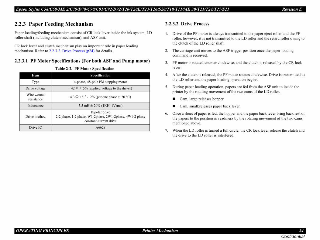
2.3 Paper Feeding Mechanismer loading/feeding mechanism consist of CR lock lever inside the ink system, LD
ler shaft (including clutch mechanism), and ASF unit.
lock lever and clutch mechanism play an important role in paper loading chanism. Refer to 2.2.3.2 Drive Process (p24) for details.
.3.1 PF Motor Specifications (For both ASF and Pump motor)
2.2.3.2 Drive Process
1. Drive of the PF motor is alwayroller, however, it is not transmthe clutch of the LD roller shaf
2. The carriage unit moves to the command is received.
3. PF motor is rotated counter clolever.
4. After the clutch is released, the the LD roller and the paper load
5. During paper loading operationprinter by the rotating moveme
Cam, large:releases hopper
Cam, small:releases paper
6. Once a sheet of paper is fed, thethe papers to the position in reamentioned above.
7. When the LD roller is turned a the drive to the LD roller is inte
Table 2-2. PF Motor SpecificationItem Specification
Type 4-phase, 48-pole PM stepping motor
Drive voltage +42 V ± 5% (applied voltage to the driver)
Wire wound resistance 4.3 Ω +8 / -12% (per one phase at 20 °C)
Inductance 5.5 mH ± 20% (1KH, 1Vrms)
Drive methodBipolar drive
2-2 phase, 1-2 phase, W1-2phase, 2W1-2phase, 4W1-2 phase constant-current drive
Drive IC A6628

Epson Stylus C58/C59/ME 2/C79/D78/C90/C91/C92/D92/T20/T20E/T23/T26/S20/T10/T11/ME 30/T21/T24/T27/S21 Revision E
O 25Confidential
2.Thinc
2.2Wh
No
2.2Thinc
PERATING PRINCIPLES Printer Mechanism
2.4 Ink System Mechanisme Ink system mechanism consists of pump mechanism and capping mechanism that ludes wiper mechanism.
.4.1 Pump Unit Mechanismen the PF motor turns, power is always transmitted to the ink system.
te * : The PF Motor rotational direction = seen from the left side of the printer.
.4.2 Capping Mechanisme Capping mechanism covers the printhead with the cap to prevent the nozzle from reasing viscosity when the printer is in stand-by state or when the printer is off.
Table 2-3. PF Motor Rotational Direction & Ink System MechanismDirection* Function
Counterclockwise Absorbs the ink by the Pump Unit
Clockwise Release pump.
Epson Stylus C58/C59/ME 2/C79/D78/C90/C91/C92/D92/T20/T20E/T23/T26/S20/T10/T11/ME 30/T21/T24/T27/S21 Revision E
O 26Confidential
2.Th
PF Motor is as follows. : Paper is fed normally : Paper is fed backwardk are as follows.
emperature is under 5 oC (41oF) by the thermistor on the
may occur depending on the situation.
1
2
3
between its home position and
lizing ink system* 4
side for IES detection.
sition.
R lock set position.
ise and sets the CR lock.
me position.
ormal power-on sequence
*1 Carriage/PF roller movement and position*2
PERATING PRINCIPLES Power-On Sequence
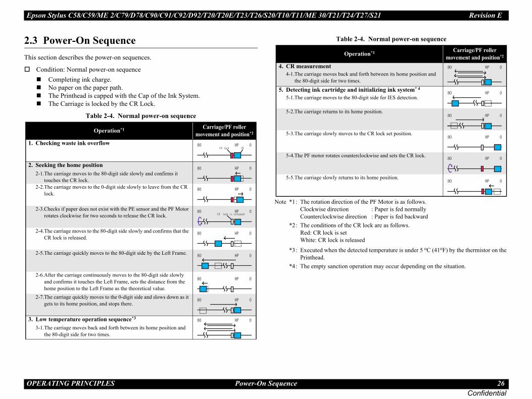
3 Power-On Sequenceis section describes the power-on sequences.
Condition: Normal power-on sequenceCompleting ink charge.No paper on the paper path.The Printhead is capped with the Cap of the Ink System.The Carriage is locked by the CR Lock.
Note *1 : The rotation direction of the Clockwise directionCounterclockwise direction
*2 : The conditions of the CR locRed: CR lock is set White: CR lock is released
*3 : Executed when the detected tPrinthead.
*4 : The empty sanction operation
Table 2-4. Normal power-on sequence
Operation*1 Carriage/PF roller movement and position*2
. Checking waste ink overflow
. Seeking the home position2-1.The carriage moves to the 80-digit side slowly and confirms it
touches the CR lock.2-2.The carriage moves to the 0-digit side slowly to leave from the CR
lock.
2-3.Checks if paper does not exist with the PE sensor and the PF Motor rotates clockwise for two seconds to release the CR lock.
2-4.The carriage moves to the 80-digit side slowly and confirms that the CR lock is released.
2-5.The carriage quickly moves to the 80-digit side by the Left Frame.
2-6.After the carriage continuously moves to the 80-digit side slowly and confirms it touches the Left Frame, sets the distance from the home position to the Left Frame as the theoretical value.
2-7.The carriage quickly moves to the 0-digit side and slows down as it gets to its home position, and stops there.
. Low temperature operation sequence*3
3-1.The carriage moves back and forth between its home position and the 80-digit side for two times.
lock
lock is released
4. CR measurement4-1.The carriage moves back and forth
the 80-digit side for two times.
5. Detecting ink cartridge and initia5-1.The carriage moves to the 80-digit
5-2.The carriage returns to its home po
5-3.The carriage slowly moves to the C
5-4.The PF motor rotates counterclockw
5-5.The carriage slowly returns to its ho
Table 2-4. N
Operation

C H A P T E R
Confidential
3T BLESHOOTING
ROU
Epson Stylus C58/C59/ME 2/C79/D78/C90/C91/C92/D92/T20/T20E/T23/T26/S20/T10/T11/ME 30/T21/T24/T27/S21 Revision E
T 28Confidential
3.Th
3.Th
sre to verify that the following conditions are all met:
be within the specification limits. trical outlet.)
rom damage, short circuit, or breakage, and must
roperly.
d in a place where it can be exposed to too high or w humidity, or abrupt temperature change.
d near waterworks, near humidifiers, near heaters sphere or in a place where the printer can be ditioner.
d in a place where volatile or inflammable gases
d in a place where it can be exposed to direct
well-ventilated place.
strong and steady level table (without an ees).
rm to the specifications.
ndling of the printer.
and remove foreign matters if any, such as paper er dust or toner.
nd the rubber rollers.
�
ROUBLESHOOTING Overview
1 Overviewis chapter describes how to solve problems.
1.1 Specified Toolsis printer does not require any specified tools for troubleshooting.
3.1.2 Preliminary CheckBefore starting troubleshooting, be su
The power supply voltage must(Measure the voltage at the elec
The power cable must be free fnot be miswired.
The printer must be grounded p
The printer should not be locatelow temperature, too high or lo
The printer should not be locateor near flames, in a dusty atmoexposed to blast from an air con
The printer should not be locateare present.
The printer should not be locatesunlight.
The printer must be located in a
The printer must be placed on ainclination larger than five degr
Be sure to use papers that confo
There should be no errors in ha
Check the inside of the printer,clips, staples, bits of paper, pap
Clean the inside of the printer a
� � � � � �Be careful to avoid electric shocks when checking the electrical circuit boards (C664 MAIN, PSE and B circuit boards) while the power is turned on.Touching an FET, transistor or heat sink with one hand while touching a metal part of the mechanism with the other hand could result in an electric shock, so carefully avoid this.After initial filling of ink has been repeated several times, immediate moving or tilting of the printer could result in leaking of ink that has not been completely absorbed by the Waste Ink Pad. When initial filling of ink has been repeated several times, check the ink remaining in the tip of the Waste Ink Tube and the waste ink not absorbed by the Waste Ink Pad before moving the printer.
� � � �
� � � �
Disassembly and reassembly of parts is often required when identifying the causes of problems. The parts should be disassembled and re-assembled correctly while referring to DISASSEMBLY/ASSEMBLY (p31) so that the operation and status of each check item can be correctly verified.Some individual part and units may require adjustment once they are removed or replaced. If removing or replacing parts which have specific instructions for adjustment included in DISASSEMBLY/ASSEMBLY (p31), be sure to make these adjustments after repairing the problem location.

Epson Stylus C58/C59/ME 2/C79/D78/C90/C91/C92/D92/T20/T20E/T23/T26/S20/T10/T11/ME 30/T21/T24/T27/S21 Revision E
T 29Confidential
3.LE
No
Remedy
InIn
nk cartridge(s) and reinstall it correctly. ink cartridge(s) with a genuine one.
Pa
no paper on the paper tray, load papers.er has stopped halfway, remove the paper, check if the ot bent, fan the paper, and load it against the edge guide.[Maintenance] button to release the error.
Dhe blank paper, or check the paper size.[Maintenance] button to eject the paper and release the
Pa
[Maintenance] button on the panel.m occurred again after pressing the button, open the
ver and remove all the papers inside the printer and t on the hopper.re there is no paper inside the printer, load paper on the
d press [Maintenance].
M (W
aste ink pad, and reset the waste ink counter using the rogram. Refer to Chapter 5 “ADJUSTMENT” (p.69) for
Fa
ower off, wait for a few seconds, and turn the power ain.l error still appears, turn the power off, remove the the hopper, and check the following:printer cover, check the ink cartridges, and reinstall ctly.here is no foreign material or papers inside the printer. any, remove them.rinter power on.
ROUBLESHOOTING Troubleshooting With LED Error Indications
2 Troubleshooting With LED Error IndicationsD error display, cause, and remedy are explained here.
te : “---”: no change.
Table 3-1. Troubleshooting With LED Error Indications
Error LED status
CausePower Maintenance
k end/ No ink cartridge/ correct ink cartridge --- On
• Ink inside Bk, Y, M, C cartridges has run out.• Ink cartridge(s) is not installed.• Non-genuine ink cartridge(s) is installed.
• Check the i• Replace the
per Out --- On
• Paper loading operation is executed when there is no paper.• Papers stopped before the PE Sensor or could not be fed.• Papers are fed without being placed against the right edge guide.• Connector of the PE sensor is disconnected.
1. If there is2. If the pap
paper is n3. Press the
ouble feed error --- On• When performing duplex printing, blank paper is ejected.• The printer detected that the paper is too long upon ejection.
1. Remove t2. Press the
error.
per jam --- OnEven though paper feeding operation is carried out for predetermined times, leading edge or back-end of the paper could not be detected.
1. Press the 2. If paper ja
printer copapers se
3. Making suhopper an
aintenance request aste ink overflow) Flashes alternately As a result of cleaning and flushing, total emission of ink has
exceeded the specific level.
Replace the wadjustment pdetails.
tal error Off Flashes fast
• Home position of the carriage could not be detected.• Abnormal external pressure is applied to the printer when the
power is on.• Carriage movement is interfered during printing.
1. Turn the pback on ag
2. If the fatapapers on
• Open the them corre
• Check is tIf there is
3. Turn the p

Epson Stylus C58/C59/ME 2/C79/D78/C90/C91/C92/D92/T20/T20E/T23/T26/S20/T10/T11/ME 30/T21/T24/T27/S21 Revision E
T 30Confidential
3.
M
CR
PF
S
PE
ROUBLESHOOTING Troubleshooting for Motors and Sensors
3 Troubleshooting for Motors and SensorsMotor
Sensor
Table 3-2. Motor Resistance and Check Pointsotor name Type Location Check point Resistance
motor Motor with DC brush CN5 Pin 1 & 2 28.8 Ω ± 10%
motor 4-phase, 200-pole HB stepping motor CN6 Pin 1 & 3 Pin 2 & 4
4.3 Ω + 8%/-12%(20ºC)
Table 3-3. Sensor Checkensor name Detecting system Location Signal level Sensor status
sensor Transmission photo interrupter CN7 pin 1 & 22.6 V or more Paper loaded
0.4 V or less No paper

C H A P T E R 1
Confidential
4DIS MBLY/ASSEMBLY
ASSE
Epson Stylus C58/C59/ME 2/C79/D78/C90/C91/C92/D92/T20/T20E/T23/T26/S20/T10/T11/ME 30/T21/T24/T27/S21 Revision E
D 32Confidential
4.Thprorea
Pround
“C
Im
If tcor
Anthe
Whcha
4.Seefoland30/
�
here is enough work space for disassembly/
ended tools for disassembling, assembling or inter.cified torque when tightening screws.s as specified. ication (p. 81) ” for details.)e was used to illustrate these disassembly and edures, the appearance of some parts may on actual product. The procedures themselves, urate for the retail model. pressed air products; such as air duster, for repair and maintenance, the use of such ing flammable gas is prohibited.
ISASSEMBLY/ASSEMBLY Overview
1 Overviewis section describes procedures for disassembling the main components of the duct. Unless otherwise specified, disassembled units or components can be ssembled by reversing the disassembly procedure.
cedures which, if not strictly observed, could result in personal injury are described er the heading “WARNING”.
AUTION” signals a precaution which, if ignored, could result in damage to equipment.
portant tips for procedures are described under the heading “CHECK POINT”.
he assembly procedure is different from the reversed disassembly procedure, the rect procedure is described under the heading “REASSEMBLY”.
y adjustments required after reassembly of components or parts are described under heading “ADJUSTMENT REQUIRED”.
en you have to remove any components or parts that are not described in this pter, refer to the exploded diagrams in the appendix.
1.1 Precautions the precautions given under the handling “WARNING” and “CAUTION” in the
lowing columns when disassembling or assembling Epson Stylus C58/C59/ME 2 Epson Stylus C79/D78/C90/C91/C92/D92/T20/T20E/T23/T26/S20/T10/T11/ME T21/T24/T27/S21.
� � � � � � Disconnect the power cable before disassembling or assembling the printer. If you need to work on the printer with power applied, strictly follow the instructions in this manual.Always wear gloves for disassembly and reassembly to avoid injury from sharp metal edges.To protect sensitive microprocessors and circuitry, use static discharge equipment, such as anti-static wrist straps, when accessing internal components.
� � � � �Make sure that treassembly. Use only recommadjusting the prObserve the speApply lubricant(See “6.1.3 LubrSince a prototypreassembly procdiffer from thosehowever, are accWhen using comcleaning during products contain
Epson Stylus C58/C59/ME 2/C79/D78/C90/C91/C92/D92/T20/T20E/T23/T26/S20/T10/T11/ME 30/T21/T24/T27/S21 Revision E
D 33Confidential
4.Us
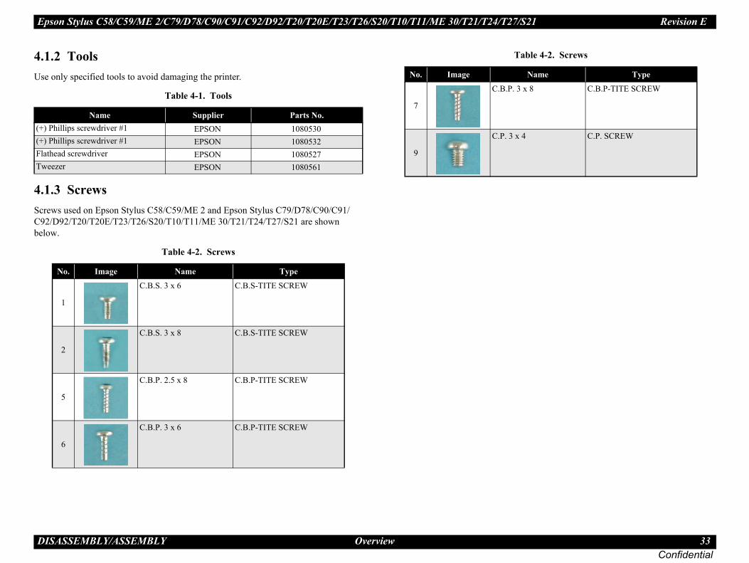
4.ScrC9bel
(+(+FlaTw
x 8 C.B.P-TITE SCREW
4 C.P. SCREW
able 4-2. Screws
Name Type
ISASSEMBLY/ASSEMBLY Overview
1.2 Toolse only specified tools to avoid damaging the printer.
1.3 Screws ews used on Epson Stylus C58/C59/ME 2 and Epson Stylus C79/D78/C90/C91/2/D92/T20/T20E/T23/T26/S20/T10/T11/ME 30/T21/T24/T27/S21 are shown ow.
Table 4-1. Tools
Name Supplier Parts No.) Phillips screwdriver #1 EPSON 1080530) Phillips screwdriver #1 EPSON 1080532thead screwdriver EPSON 1080527eezer EPSON 1080561
Table 4-2. Screws
No. Image Name Type
1
C.B.S. 3 x 6 C.B.S-TITE SCREW
2
C.B.S. 3 x 8 C.B.S-TITE SCREW
5
C.B.P. 2.5 x 8 C.B.P-TITE SCREW
6
C.B.P. 3 x 6 C.B.P-TITE SCREW
7
C.B.P. 3
9
C.P. 3 x
T
No. Image

Epson Stylus C58/C59/ME 2/C79/D78/C90/C91/C92/D92/T20/T20E/T23/T26/S20/T10/T11/ME 30/T21/T24/T27/S21 Revision E
D 34Confidential
4.If awo
airpair, be sure to secure the CR Unit following the
NIT BEFORE PACKING
position.
the front of the printer with a flathead screwdriver.
ghtly until it comes in contact with the Carriage Lock.
trong tape to the Cartridge Cover located on the carriage.
the strong tape to the Upper Housing.
e strong tape to the left side of the carriage.
n move slightly between the Home position and the the CR unit back into contact with the Carriage
-1. Securing CR Unit
C
M
A
Lu
Fu
the ink cartridges installed rectly?
CheckedNot necessary
e all relevant protective materials n attached to the printer?
CheckedNot necessary
e all the relevant items been uded in the package?
CheckedNot necessary
Work Completion CheckCheck Point Status
Strong Tape
Unit
Upper Housing
Cartridge Cover
ISASSEMBLY/ASSEMBLY Overview
1.4 Work Completion Checkny service is made to the printer, use the checklist shown below to confirm all rks are completed properly and the printer is ready to be returned to the user.
4.1.5 Caution After RepBefore shipping the product after reprocedure below.
HOW TO SECURE THE CR U
(1) Move the CR Unit to the Home
(2) Lock the Carriage Lock toward (See 4.5.2 Printhead (p43))
(3) Move the CR Unit to the center sli
(4) Attach the center portion ( ) of a s
(5) Attach the right portion ( ) of
(6) Attach the left portion ( ) of th
(7) Check to see that the CR Unit caCarriage Lock position. Then bring Lock, and pack the printer.
Figure 4
Table 4-3. Work Completion Checklassification Item Check Point Status
ain Unit
Self-test Is the operation normal?CheckedNot necessary
ON-line Test Is the printing successfulCheckedNot necessary
Printhead Is ink discharged normally from all the nozzles?
CheckedNot necessary
Carriage Mechanism
Does it move smoothly?CheckedNot necessary
Is there any abnormal noise during its operation?
CheckedNot necessary
Is the CR Motor at the correct temperature? (Not too hot to touch?)
CheckedNot necessary
Paper Feeding MEchanism
Is paper advanced smoothly?No paper jamming?No paper skew?No multiple feeding?No abnormal noise?
CheckedNot necessary
Is the PF Motor at correct temperature?
CheckedNot necessary
Is the paper path free of any obstructions?
CheckedNot necessary
djustment Specified Adjustment
Are all the adjustment done correctly?
CheckedNot necessary
brication Specified Lubrication
Are all the lubrication made at the specified points?
CheckedNot necessary
Is the amount of lubrication correct?CheckedNot necessary
nction ROM Version Version:CheckedNot necessary
PackingInk Cartridge Are
cor
Protective materials
Havbee
Others Attachments, Accessories
Havincl
Table 4-3. Classification Item
CR
Carriage Lock

Epson Stylus C58/C59/ME 2/C79/D78/C90/C91/C92/D92/T20/T20E/T23/T26/S20/T10/T11/ME 30/T21/T24/T27/S21 Revision E
D 35Confidential
4.So 3/T26/S20/T10/T11/ME 30/T21/T24/T27/S21 dif e the respective pages for details.
ducts*1
Reference PageB C
Pr
-- -- see 4.6.1 Printhead (p64)
see 4.5.2 Printhead (p43)
ISASSEMBLY/ASSEMBLY Overview
1.6 Procedural Differences between the Models me parts installed on Epson Stylus C58/C59/ME 2, Epson Stylus C79/D78/C90/C91/C92/D92 and Epson Stylus T20/T20E/T2fer from each other as described in the table below, and for that, there are some procedural differences between the models. Se
� � � �
� � � �
Since Epson Stylus C79/D78/C90/C91/C92/D92 model was used to make this manual, the appearance of some parts may differ from those on other model. The procedures are the same for both models unless otherwise noted except for the one described in the table below.
Item DescriptionPro
A
inthead
You need to cut off the Cartridge Cover Hinge and remove the Cartridge Cover to take out the Printhead.
You need to remove the Sub FFC Guide to take out the Printhead. --
Cartridge Cover Cartridge Cover Hinge
Sub FFC Guide

Epson Stylus C58/C59/ME 2/C79/D78/C90/C91/C92/D92/T20/T20E/T23/T26/S20/T10/T11/ME 30/T21/T24/T27/S21 Revision E
D 36Confidential
No
Sh
-- see 4.5.8 EJ Frame Assy/EJ Roller (p54)
-- see 4.5.9 Main Frame (p56)
W
-- -- see 4.6.2 Waste Ink Pads (p67)
see 4.5.11 Waste Ink Pads (p61)
ducts*1
Reference PageB C
ISASSEMBLY/ASSEMBLY Overview
te *1 : “A”: Epson Stylus C58/C59/ME 2 “B”: Epson Stylus C79/D78/C90/C91/C92/D92 “C”: Epson Stylus T20/T20E/T23/T26/S20/T10/T11/ME 30/T21/T24/T27/S21
ield Plates
Shield Plate L is small.
Shield Plate L is large. --
aste Ink Pad
7 parts
9 parts --
Item DescriptionPro
A

Epson Stylus C58/C59/ME 2/C79/D78/C90/C91/C92/D92/T20/T20E/T23/T26/S20/T10/T11/ME 30/T21/T24/T27/S21 Revision E
D 37Confidential
4.ThUndisFodia
ly different from model to model are described nd “Reassembly”.
Note: Shown in the dotted-line is not the shortest procedure, but is necessary to proceed to the next step.
“4.5.7 Power Supply Board”
(p53)
EJ Frame J Roller”
p54)
5.12 PF r” (p62)
5.13 PF r” (p63)
ortest Way to Remove the Main Framets to repair is the ones marked with “*” in the flowchart
re’s another way to remove the parts until the Main own in the flowchart. Refer to “4.7 The Shortest Way to
the Main Frame. (p. 68) ”
ISASSEMBLY/ASSEMBLY Disassembly Procedures
2 Disassembly Proceduresis section explains the procedures for disassembling the product. less otherwise stated, reassembly should be carried out in the reverse order of the assembly procedure. r detailed engagement relations among main components, refer to the exploded grams in the Appendix.
Figure 4-2. Disassembling Flowchart
� � � �
� � � �
Procedures partialin “Check Point” a
“4.3.1 Upper Housing” (p38)
“4.5.1 Hopper” (p42)
“4.4.1 Main Board” (p40)
*“4.5.10 LD Roller/ASF Unit” (p59)
“4.5.2 Printhead” (p43)
“4.5.3 CR Scale” (p46)
“4.5.4 CR Motor” (p47)
“4.5.9 Main Frame” (p56)
Ink System (Cap Assy) (p51)
“4.5.8 Assy/E
(
START
*“4.Rolle
*“4.Moto
*“4.5.11 Waste Ink Pads” (p61)
*Ink System (Pump Assy) (p51)
“4.5.6 Ink System removal” (p51)
“4.5.5 CR Unit/Timing Belt”
(p48)
* The ShIf the paronly, theFrame shRemove

Epson Stylus C58/C59/ME 2/C79/D78/C90/C91/C92/D92/T20/T20E/T23/T26/S20/T10/T11/ME 30/T21/T24/T27/S21 Revision E
D 38Confidential
4.4.
lease the tabs (x2, ) on the front side of the
inside as shown in the figure to release the
oving Upper Housing (2)king care not to scratch the Hopper with the
oving Upper Housing (3)
�
Push here
Upper Housing
pper
Upper Housing
ISASSEMBLY/ASSEMBLY Removing Housing
3 Removing Housing3.1 Upper Housing
Part/Unit that should be removed before removing Upper Housing None
Removal Procedure
1. Remove the screws (x2) on the back of the printer.2. While releasing the tab (x1) on the back, release the tabs (x2) on both sides of
the printer with a flathead screwdriver.
Figure 4-3. Removing Upper Housing (1)
3. Push the marked area ( )to reprinter (Arrows ).
4. Push the dotted area ( ) from tab (x1, ) in the middle.
Figure 4-4. Rem5. Remove the Upper Housing ta
tabs.
Figure 4-5. Rem
� � � �When releasing the tabs on the sides, be careful not to scratch the surface with a screwdriver. The coating is fragile and can be easily damaged.
C.B.S 3X6 (Torque: 6±1Kgf.cm)
Upper Housing
Push here
Push here from inside
:Tab
Ho

Epson Stylus C58/C59/ME 2/C79/D78/C90/C91/C92/D92/T20/T20E/T23/T26/S20/T10/T11/ME 30/T21/T24/T27/S21 Revision E
D 39Confidential
mbling the Shield Plate Front for some w the steps below. late Front tape and remove the grounding spring 1,2.sions of each of the two holes outwardly with a iver or the like and remove the Shield Plate Front.g, be sure to straighten the protrusions of store their original state.ld Plate Fronts of the plate over the dowels on the base y will go. g spring 1, 2 and attach a 20 x 18 mm piece of ing it as described/shown below.
5mm from the edge (A), attach the right 6- of the tape to the Shield Plate Front. Fold dge (B), and wrap the acute edge of the t to let the tape run over the frame edge. bling, make sure the plate is kept in ct with the frame.
ng the Base Frame, remove the Shield Plate e current Base Frame and reinstall it to a e Base Frame supplied as an ASP does not rt.
ing and reassembling Shield Plate Front
s with protrusions & Dowel
A: 5mm
B: 6-7mm
L: 20mm
Acetate Tape: 20mm x 18mm
Shield Plate Front
ISASSEMBLY/ASSEMBLY Removing Housing
The Ink Position Label is not included in the Upper Housing.When installing the Upper Housing, order the label separately and attach the Ink Position Label to the place shown below.
Figure 4-6. Installing Ink Position Label
In Epson Stylus C79/D78/C90/C91/C92/D92’s case: • When reassembling the Upper Housing, be sure to check there
is no ink on the Shield Plate Upper. If there is some ink stein on it, be sure to wipe it out before reassembling.
• When installing the Upper Housing, be sure to check the GND Plate M/B comes in contact with the Shield Plate Upper.
Figure 4-7. Shield Plate Upper
Upper HousingInk Position Label
Install the label in this position with Black to the right.
Upper Housing
Shield Plate Upper
If removing and reassereasons, be sure to follo
Removing Shield P1. Peel off the acetate2. Bend the four protru
flat-head precision drNOTE. After removin
the holes to reReassembling Shie
1. Insert the two holeframe as far as the
2. Install the groundinacetate tape position
• Leaving a space of7mm-width portionthe tape along the eplate. Be careful no
NOTE 1.After reassemabsolute conta
NOTE 2.When replaciFront from thnew one as thinclude the pa
Figure 4-8. Remov
Hole
Grounding Spring
Front Left

Epson Stylus C58/C59/ME 2/C79/D78/C90/C91/C92/D92/T20/T20E/T23/T26/S20/T10/T11/ME 30/T21/T24/T27/S21 Revision E
D 40Confidential
4.
4.
nnector Layout of Main Board
te Clip from the Main Board Assy.om the Main Board.
Removing Main Board (2)
CN8 CN6
Shield Plate
Main Board Assy.
ISASSEMBLY/ASSEMBLY Removing Board
4 Removing Board
4.1 Main BoardPart/Unit that should be removed before removing Main Board
Upper Housing /Hopper
Removal Procedure
1. Peel off the acetate tapes (x2) from the Main Frame.2. Disconnect the following connector cables (x4) and FFCs (x2) from the
connectors on the Main Board Assy.• CN1: Head FFC• CN3: Head FFC (Backside)• CN5: PE Detector Connector Cable• CN6: PF Motor Connector Cable• CN7: CR Motor Connector Cable• CN8: Power Supply Board Connector Cable
3. Remove the screws (x4), and remove the GND Plate M/B and the Main Board Assy.
Figure 4-9. Removing Main Board (1)
Figure 4-10. Co
4. Remove the Grounding Pla5. Remove the Shield Plate fr
Figure 4-11.
Main Board Assy.FFCs
Connectors
C.B.S 3X6 (Torque: 8±1Kgf.cm)
GND Plate
CN7
CN5
CN1
CN3
Grounding Plate Clip
Epson Stylus C58/C59/ME 2/C79/D78/C90/C91/C92/D92/T20/T20E/T23/T26/S20/T10/T11/ME 30/T21/T24/T27/S21 Revision E
D 41Confidential
�
ISASSEMBLY/ASSEMBLY Removing Board
� � � � �
� � � � �
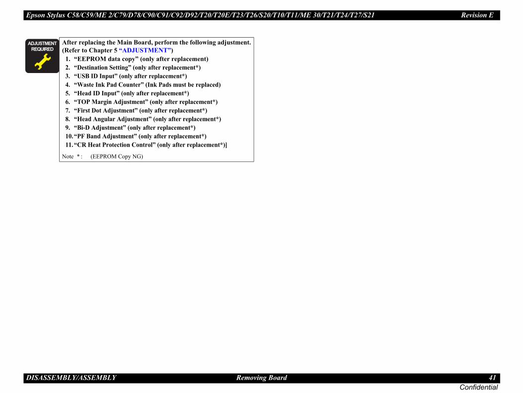
After replacing the Main Board, perform the following adjustment. (Refer to Chapter 5 “ADJUSTMENT”)1. “EEPROM data copy” (only after replacement)2. “Destination Setting” (only after replacement*)3. “USB ID Input” (only after replacement*)4. “Waste Ink Pad Counter” (Ink Pads must be replaced)5. “Head ID Input” (only after replacement*)6. “TOP Margin Adjustment” (only after replacement*)7. “First Dot Adjustment” (only after replacement*)8. “Head Angular Adjustment” (only after replacement*)9. “Bi-D Adjustment” (only after replacement*)10.“PF Band Adjustment” (only after replacement*)11.“CR Heat Protection Control” (only after replacement*)]
Note * : (EEPROM Copy NG)

Epson Stylus C58/C59/ME 2/C79/D78/C90/C91/C92/D92/T20/T20E/T23/T26/S20/T10/T11/ME 30/T21/T24/T27/S21 Revision E
D 42Confidential
4.
4.
1.
2.
3.
the Hopper, be sure to adjust the position of the ing the steps below.
arriage Lock. (See “4.5.2 Printhead” (p43))R Unit to the center of the printer.osition of LD Roller turning the EJ Roller
ion: the flat part facing inward.er position: inner most.
alling Hopper and Compression Spring 1.94
Hopper, perform the following adjustment. “ADJUSTMENT”)djustment”
tment”
EJ Roller
Paper Back Lever
lat part of LD Roller
Inward
ISASSEMBLY/ASSEMBLY Disassembling Printer Mechanism
5 Disassembling Printer Mechanism
5.1 HopperPart/Unit that should be removed before removing Hopper
Upper Housing
Removal Procedure
Pull open the Bearing slightly (Arrow ), to release the guide pin (A).
Remove the Hopper (Arrow ) pulling out the guide pin (B).
Remove the Compression Spring 1.94.
Figure 4-12. Removing Hopper and Compression Spring 1.94
Compression Spring 1.94Hopper
Bearing
Guide Pin (B)
Guide Pin (A)
Before installingLD Roller follow1. Unlock the C2. Move the C3. Adjust the p
clockwise.
• LD Roller posit • Paper Back Lev
Figure 4-13. Inst
� � � � � �
� � � � �
After replacing the (Refer to Chapter 5
1. “TOP Margin A2. “PF Band Adjus
F

Epson Stylus C58/C59/ME 2/C79/D78/C90/C91/C92/D92/T20/T20E/T23/T26/S20/T10/T11/ME 30/T21/T24/T27/S21 Revision E
D 43Confidential
4. d remove all the Ink Cartridges from the CR Unit.tabs.
-15. Releasing FFCs
(x2) that are connected to the CSIC Board and the
Disconnecting Head FFCs
Tabs
Cartridge Cover
ISASSEMBLY/ASSEMBLY Disassembling Printer Mechanism
5.2 Printhead
Part/Unit that should be removed before removing Printhead
Upper Housing
Removal Procedure
1. Unlock the Carriage Lock with a flathead screwdriver or a similar tool, and move the CR Unit to the center of the printer.
Figure 4-14. Unlocking Carriage Lock and Moving CR Unit to the Center
2. Open the Cartridge Cover an3. Release the FFCs from the
Figure 4
4. Disconnect the Head FFCs CR Encoder Board.
Figure 4-16.
� � � �
� � � �
The removal procedures differ depending on the model. For Epson Stylus C58/C59/ME 2, see “4.6.1 Printhead” (p64).
Carriage Lock CR Unit
Locked Unlocked
FFCs
Head FFCs

Epson Stylus C58/C59/ME 2/C79/D78/C90/C91/C92/D92/T20/T20E/T23/T26/S20/T10/T11/ME 30/T21/T24/T27/S21 Revision E
D 44Confidential
t the blade of the Sub FFC Guide from the slit, and pulling out the guide pin (x1) from the notch.
Removing Sub FFC Guide
lift up the Printhead with a longnose pliers.
. Removing Printhead (1)
age the nozzles or the ink supply needles of the
Sub FFC GuideBlade
Guide PinNotch
Slit
.cm)
ISASSEMBLY/ASSEMBLY Disassembling Printer Mechanism
5. Release the tabs (1) and (2) with a flathead precision screwdriver, and remove the Holder Board Assy upward.
Figure 4-17. Removing Holder Board Assy
6. Release the tab and pull ouremove the Sub FFC Guide
Figure 4-18.
7. Remove the screw (x3) and
Figure 4-19
Tab (1)
Tab (2)
HolderBoard Assy.
Tab (1)
Holder Board Assy
Tab (2)
Tab (1)
CR Unit
Tab (2)
CR Unit
� � � � �Do not touch or damPrinthead.
Notch
C.B.P 2.5X8 (Torque: 3±1Kgf
Epson Stylus C58/C59/ME 2/C79/D78/C90/C91/C92/D92/T20/T20E/T23/T26/S20/T10/T11/ME 30/T21/T24/T27/S21 Revision E
D 45Confidential
he Holder Board Assy, make sure to check if ly installed in the right position. The assy is led in the wrong position.
o remove the Cartridge Cover, when replacing f the Epson Stylus C79/D78. But if the quired for some reasons, refer to “4.6.1 or the replacement procedures.
Label is not included in the Cartridge Cover.he Cartridge Cover, order the label separately k Position Label to the place shown below.
-22. Installing Ink Position Label
cing the Printhead, perform the adjustment in (Refer to Chapter 5 “ADJUSTMENT”)nly after replacement) (only after replacement)
djustment”tment”djustment”
nt”tment”
Cartridge Cover
position with ight.
ISASSEMBLY/ASSEMBLY Disassembling Printer Mechanism
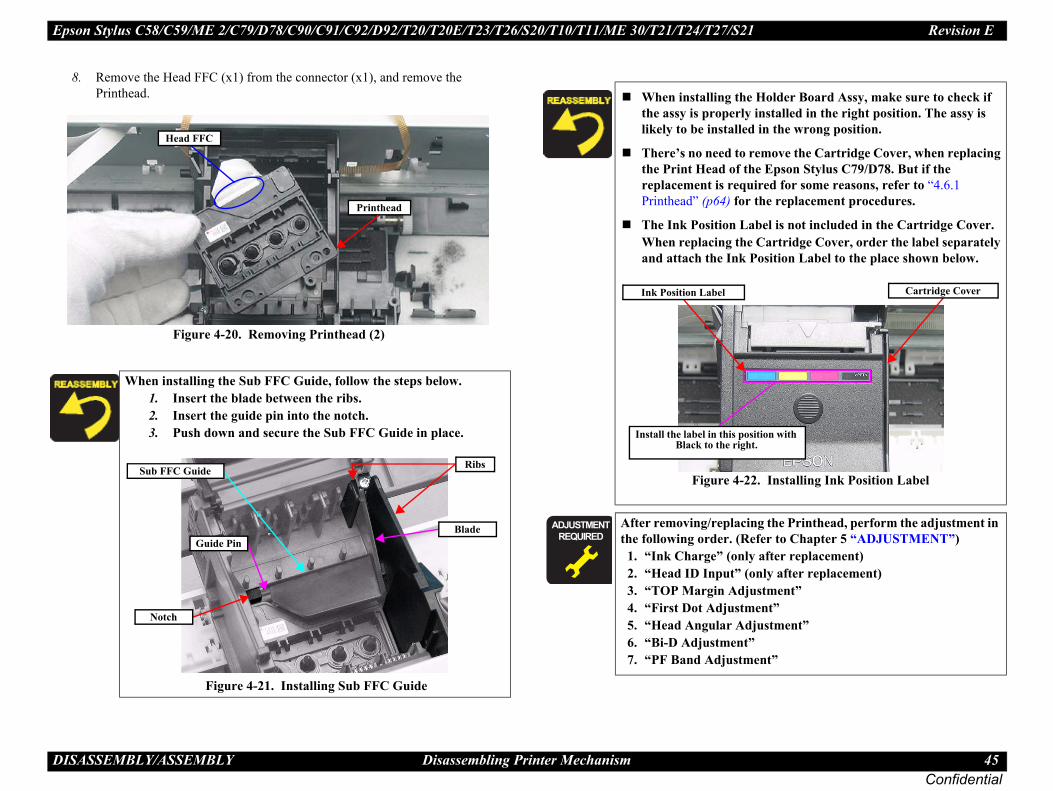
8. Remove the Head FFC (x1) from the connector (x1), and remove the Printhead.
Figure 4-20. Removing Printhead (2)
When installing the Sub FFC Guide, follow the steps below.1. Insert the blade between the ribs.2. Insert the guide pin into the notch.3. Push down and secure the Sub FFC Guide in place.
Figure 4-21. Installing Sub FFC Guide
Head FFC
Printhead
Guide Pin
Sub FFC Guide Ribs
Blade
Notch
When installing tthe assy is properlikely to be instal
There’s no need tthe Print Head oreplacement is rePrinthead” (p64) f
The Ink PositionWhen replacing tand attach the In
Figure 4
� � � � � �
� � � � �
After removing/replathe following order.
1. “Ink Charge” (o2. “Head ID Input”3. “TOP Margin A4. “First Dot Adjus5. “Head Angular A6. “Bi-D Adjustme7. “PF Band Adjus
Ink Position Label
Install the label in thisBlack to the r

Epson Stylus C58/C59/ME 2/C79/D78/C90/C91/C92/D92/T20/T20E/T23/T26/S20/T10/T11/ME 30/T21/T24/T27/S21 Revision E
D 46Confidential
4. ng 3.289 from the hook of the Main Frame. rees as shown in the figure and remove the scale
. Removing CR Scale (3)
�
CR Scale, pay attention to the following
ust be set between the sides of the CR Encoder touching either side. If the CR Scale is rubbing all (emitter or receiver), it should be re-
the CR Scale should be facing upward.g 3.289 should not be twisted.
CR Scale
n Spring 3.289
Chipped
90 º
ISASSEMBLY/ASSEMBLY Disassembling Printer Mechanism
5.3 CR Scale
Part/Unit that should be removed before removing CR Scale
Upper Housing
Removal Procedure
1. Release the right end of the CR Scale from the tab. 2. Release the CR Scale from the slit of the CR Encoder Sensor.
Figure 4-23. Removing CR Scale (1)
3. Release the Extension Spri4. Rotate the CR Scale 90 deg
from the Main Frame.
Figure 4-24
� � � �Pay attention to the following instructions:
• Do not touch the CR Scale with bare hands. • Do not damage the CR Scale. • Do not stretch Extension Spring 3.289 too much.
CR Scale
TabCR Scale
Epson Stylus C79/D78’s Case
Slit of CR Encoder Sensor
Tab
CR Scale
Epson Stylus C58/C59/ME2’s Case
When installing the instructions.
The CR Scale mSensor, but not against either winstalled.Chipped part ofExtension Sprin
Extensio
Hook

Epson Stylus C58/C59/ME 2/C79/D78/C90/C91/C92/D92/T20/T20E/T23/T26/S20/T10/T11/ME 30/T21/T24/T27/S21 Revision E
D 47Confidential
4. Belt by pressing the Driven Pulley Holder in wn in the figure, and release the Timing Belt
otor.move the CR Motor from the Main Frame.
ng Belt and Removing CR Motor
�
otor, perform the following adjustment. JUSTMENT”)
ent”stment”
Control” (only after replacement)
Main Frame
CR MotorPinion Gear
Timing Belt
C.B.S 3X6 (Torque: 6±1Kgf.cm)
ISASSEMBLY/ASSEMBLY Disassembling Printer Mechanism
5.4 CR MotorPart/Unit that should be removed before removing CR Motor
Upper Housing /Hopper /CR Scale
Removal Procedure
1. Disconnect the Head FFCs from the Main Board, and release the CR Motor connector cable from the tabs (x5) on the Main Frame.
2. Disconnect the CR Motor Connector Cable from the Main Board.
Figure 4-25. Disconnecting CR Motor Connector Cable
3. Loosen the tension of the Timingthe direction of the arrow as shofrom the pinion gear of the CR M
4. Remove the screws (x2), and re
Figure 4-26. Releasing Timi
� � � �After releasing the Timing Belt, temporarily secure the belt to the Cartridge Cover with a tape or the like so as not to allow the grease to come in contact with the Timing Belt. Contaminating the belt with grease can result in malfunction of the printer.
Tabs
CR Motor Connector Cable
Main BoardCR Motor Head FFCs
� � � � � �
� � � � �
After replacing the CR M(Refer to Chapter 5 “AD1. “First Dot Adjustm2. “Head Angular Adju3. “Bi-D Adjustment”4. “CR Heat Protection
Driven Pulley Holder
Timing Belt

Epson Stylus C58/C59/ME 2/C79/D78/C90/C91/C92/D92/T20/T20E/T23/T26/S20/T10/T11/ME 30/T21/T24/T27/S21 Revision E
D 48Confidential
4.
Up
�
ace part of the Timing Belt into the groove
FC differs from model to model, therefore o the routing procedure of corresponding
78/C90/C91/C92/D92: p 4859/ME 2: p 4920E/T23/T26/S20/T10/T11/ME 30/T21/
p 50/D78/C90/C91/C92/D92's CaseC through the Hole of the Main Frame.
9. Installing Head FFC (1)
FFC with Rib A, and C.
0. Installing Head FFC (2)
>>To be continued to the next page.
Hole
Head FFC
Ribs
Ribs
d FFC
ISASSEMBLY/ASSEMBLY Disassembling Printer Mechanism
5.5 CR Unit/Timing BeltPart/Unit that should be removed before removing CR Unit/Timing Belt
per Housing /Hopper /Print Head /Ink System (Cap Assy)/CR Scale/CR Motor
Removal Procedure
CR Unit Removal1. Remove the screw (x1), and remove the CR Scale Holder.• In the case of Epson Stylus C58/C59/ME2
Remove the screw (x1), and remove the CR Scale Holder and the CR Unit Stopper.2. Remove the CR Unit by sliding it in the direction of the arrow.
Figure 4-27. Removing CR Scale Holder
Timing Belt Removal1. Remove the Timing Belt from the groove of the CR Unit.
.
Figure 4-28. Removing Timing Belt
� � � �After releasing the Timing Belt, temporarily secure the belt to the Cartridge Cover with a tape or the like so as not to allow the grease to come in contact with the Timing Belt. Contaminating the belt with grease can result in malfunction of the printer.
CR Scale HolderCR Unit CR Unit Stopper
Epson Stylus C58/C59/ME2’s Case
C.B.S 3X6 (Torque: 8±1Kgf.cm)
CR Scale Holder
Groove of CR UnitTiming Belt
Insert the wavy-surfof the CR Unit.Routing the Head Fmake sure to refer tmodel.
• Epson Stylus C79/D • Epson Stylus C58/C • Epson Stylus T20/T
T24/T27/S21:Epson Stylus C79
1. Put the Head FF
Figure 4-2
2. Secure the Head
Figure 4-3
Main Frame
Hea

Epson Stylus C58/C59/ME 2/C79/D78/C90/C91/C92/D92/T20/T20E/T23/T26/S20/T10/T11/ME 30/T21/T24/T27/S21 Revision E
D 49Confidential
58/C59/ME 2's CaseFFC through the Hole of the Main Frame. 9 (p.48))ad FFC with Rib A, and B. (p.48)) Head FFC and secure it with Rib A again. (p.49))FFC through the Ferrite Core with double ind.ead FFC to CN1, CN3 of the Main Board.
ain Board ” (p.40))rrite Core to the Main Frame with double the following standard. the Ferrite Core must be 1mm above the king on the Main Frame.
-33. Installing Head FFC (5)
>>To be continued to the next page.
1mm
Ferrite Core CN1,CN3
Marking Main Board
ISASSEMBLY/ASSEMBLY Disassembling Printer Mechanism
>> From the previous page.
3. Fold back the Head FFC and secure it with Rib A again.
Figure 4-31. Installing Head FFC (3)
4. Connect the Head FFC to CN1, CN3 of the Main Board. (see “ 4.4.1 Main Board ” (p.40))
5. Arrange FFC1 on top of FFC2.6. Secure the Head FFC with a Strong tape by the following
standard. • Size: 60mm (L) x 18mm (W) • The tape must be attached vertically to the Head FFC. • The lower end of the tape must be 1-2 mm below the upper
side of the hook hole as shown in the figure.
Figure 4-32. Installing Head FFC (4)
Head FFC
1-2mmFFC1
FFC2
CN1,CN3
Hook hole
Strong Tape (60mm x 18mm)
Epson Stylus C1. Put the Head
(see Figure 4-22. Secure the He
(see Figure 4-293. Fold back the
(see Figure 4-314. Put the Head
sided tape beh5. Connect the H
(see “ 4.4.1 M6. Secure the Fe
sided tape by • The top end of
horizontal mar
Figure 4
Main Frame

Epson Stylus C58/C59/ME 2/C79/D78/C90/C91/C92/D92/T20/T20E/T23/T26/S20/T10/T11/ME 30/T21/T24/T27/S21 Revision E
D 50Confidential
ISASSEMBLY/ASSEMBLY Disassembling Printer Mechanism
>> From the previous page.
Epson Stylus T20/T20E/T23/T26/S20/T10/T11/ME 30/T21/T24/T27/S21's Case
1. Put the Head FFC through the Hole of the Main Frame. (see Figure 4-29 (p.48))
2. Secure it with Rib A, then fold it back. (see Figure 4-29 (p.48))
3. Put the FFC1 and FFC2 through the Ferrite Core.4. Connect the Head FFC to CN1, CN3 of the Main Board.
(see “ 4.4.1 Main Board ” (p.40))5. Secure the FFC and the Ferrite Core with strong tape
(60mm) according to the standard given below. • Align the top of the Ferrite Core in parallel with the
marking shown below. • The tape must be attached vertically to the Head FFC. • The lower end of the tape must be 3-4 mm below the upper
side of the hook hole as shown in the figure.
Figure 4-34. Installing Head FFC (6)
Strong Tape (60mm x 18mm)
Hook hole
3-4mm
Marking
CN1,CN3Ferrite Core
FFC1
FFC2

Epson Stylus C58/C59/ME 2/C79/D78/C90/C91/C92/D92/T20/T20E/T23/T26/S20/T10/T11/ME 30/T21/T24/T27/S21 Revision E
D 51Confidential
4. Cap Assy, and remove the Cap Assy.
moving Ink System (1)
Assy) (p51)
elt (p48))etween the tab (1) and the rib, and release the direction of the arrow .tion of the arrow .
moving Ink System (2)
�
H
Ca
C
Cap Assy
Tab (1)
Rib Pump Assy..
ISASSEMBLY/ASSEMBLY Disassembling Printer Mechanism
5.6 Ink System removalPart/Unit that should be removed before removing Ink System
Upper Housing
Figure 4-35. Component Formation of Ink System
Removal procedure
Ink System (Cap Assy)1. Release the tabs (x2) that secure the Cap Assy, and detach the Cap Assy.
Figure 4-36. Removing Ink System (1)
2. Detach the Ink Tube from the
Figure 4-37. Re
Ink System (Pump Assy)
1. Remove the Main Board (p40)2. Remove the Printhead (p43)3. Remove the Ink System (Cap 4. Remove the CR Scale (p46)5. Remove the CR Motor (p47)6. Remove the CR Unit/Timing B7. Remove the Main Frame (p568. Insert a flathead screwdriver b
tab (1) while pushing it in the 9. Release the tab (2) in the direc
Figure 4-38. Re
� � � �Do not touch or damage the Sealing Rubber or the Head Cleaner when performing the following work.Mark the connection location before removing the Ink Tube.When removing the Ink System, follow the procedure below.
1. Detach the Cap Assy.2. Detach the Dump Assy.3. Remove the whole Ink System.
ead Cleaner
p Assy
Sealing Rubber
Pump Assy
Tabs
ap Assy
Ink Tube
Pump Assy
Tab (2)

Epson Stylus C58/C59/ME 2/C79/D78/C90/C91/C92/D92/T20/T20E/T23/T26/S20/T10/T11/ME 30/T21/T24/T27/S21 Revision E
D 52Confidential
the Cap Assy, follow the steps described below.e between the ribs as shown in the figure below.ssy and match the tabs (x2) and lock them.
ube. (Figure 4-38)
ure 4-42. Installing Ink System
g the Pump Assy, follow the steps described
(x2) of the Pump Assy with the positioning e Frame Base. (Figure 4-36)ube into the hole of the Frame Base, and insert the nnector.e with the Tube Stopper as shown in the figure.
Tube into the hole of the connector of Waste Ink
ure 4-43. Installing Ink Tube(2)
Ink Tube
mm
Connector
ISASSEMBLY/ASSEMBLY Disassembling Printer Mechanism
10. Pull out the Ink Tube and the Tube Stopper (Figure 4-43) from the connector of the Waste Ink Pads, and draw out the tube from the hole of the Frame Base.
11. Remove the pump system.
Figure 4-39. Removing Ink System (3)
When installing the Cap Assy, be sure to attach the Ink Tube up to the edge as shown below without any space between.
Figure 4-40. Installing Ink TubeWhen inserting the Ink Tube into the connector, be careful not to touch the Paper Back Lever.
Figure 4-41. Paper Back Lever behind Ink Tube
Ink Tube Connector of Waste Ink Pad
Hole of Frame Base
Ink Tube
Ink Tube Paper Back Lever
When installing1. Arrange the tub2. Place the Cap A
(Figure 4-34)3. Attach the Ink T
Fig
When installinbelow.
1. Match the tabsholes (x2) of th
2. Insert the Ink Ttube into the co
3. Arrange the tub4. Attach the Ink
Pad.
Fig
Ink Tube
Ribs
10±1
Tube Stopper

Epson Stylus C58/C59/ME 2/C79/D78/C90/C91/C92/D92/T20/T20E/T23/T26/S20/T10/T11/ME 30/T21/T24/T27/S21 Revision E
D 53Confidential
4.
e through the hole of the Frame Base.
oving Power Supply Board (3)
wer Supply Board upside down as shown in the figure is only used to show the location of the ess arrangement.
Power Supply Board, arrange the cable into place the ferrite core into the hook in the area p.53).
-47. Installing Power Supply Board
Hole
Connector Cable
Frame Base
ISASSEMBLY/ASSEMBLY Disassembling Printer Mechanism
5.7 Power Supply BoardPart/Unit that should be removed before removing LD Roller/ASF Unit
Upper Housing
Removal procedure
1. Peel off the acetate tape from the Frame Base.2. Disconnect the connector cable from the connector (CN8) of the Main Board.
Figure 4-44. Removing Power Supply Board (1)
3. Remove the screw (x1), and remove the Power Supply Board in the direction of the arrow.
Figure 4-45. Removing Power Supply Board (2)
4. Pull out the connector cabl
Figure 4-46. Rem
CN8
Acetate Tape
C.B.P 3X6 (Torque: 6±1Kgf.cm)
Power Supply Board
Cable of Power Supply Board
Cable of PF Motor
� � � � �Do not turn the Pofigure below. This parts and the harn
When installing thethe slit , and
of Figure 4-45 (
Figure 4
Power Supply Board
Bottom
Ferrite core
Hook

Epson Stylus C58/C59/ME 2/C79/D78/C90/C91/C92/D92/T20/T20E/T23/T26/S20/T10/T11/ME 30/T21/T24/T27/S21 Revision E
D 54Confidential
4.r between the rib and the Spur Gear, 59.6 and push
the arrow, and remove the Spur Gear, 59.6
. Removing EJ Roller (1)
rrow ), and remove the EJ Roller (Arrow ).
. Removing EJ Roller (2)
EJ Roller
Rib
EJ Roller
Bearing
ISASSEMBLY/ASSEMBLY Disassembling Printer Mechanism
5.8 EJ Frame Assy/EJ RollerPart/Unit that should be removed before removing EJ Frame Assy/EJ RollerUpper Housing
Removal procedureEJ Frame Assy removal
1. Remove the screws (x2) and remove the EJ Frame Assy.
Figure 4-49. Removing EJ Frame Assy.
EJ Roller Removal
2. Insert a flathead screwdrivethe gear in the direction of
Figure 4-50
3. Pull the bearing slightly (A
Figure 4-51
� � � �
� � � �
When installing Spur Gear, 59. 6 and the EJ Roller, be sure to install new ones. These parts cannot be reused.Before starting the removal procedure, the preparing procedure is needed.
In the case of Epson Stylus C79/D78/C90/C91/C92/D92Remove the Grounding Spring (See Figure 4-53 (p.56)) from
the EJ Frame Assy.In the case of Epson Stylus C58/C59/ME2/T20/T20E/T23/T26/S20/T10/T11/ME 30/T21/T24/T27/S21
Remove the screw (x1), and release the hooks and remove the Shield Plate L.
Figure 4-48. Epson Stylus C58/C59/ME2’s Preparation for removal
Hooks
C.B.S 3X6 (Torque: 6±1Kgf.cm)Shield Plate L
EJ Frame Assy
Grounding Spring C.B.P 3X8 (Torque: 6±1Kgf.cm)
Spur Gear,59.6

Epson Stylus C58/C59/ME 2/C79/D78/C90/C91/C92/D92/T20/T20E/T23/T26/S20/T10/T11/ME 30/T21/T24/T27/S21 Revision E
D 55Confidential
�
ISASSEMBLY/ASSEMBLY Disassembling Printer Mechanism
Follow the procedure below to install the Grounding Spring (Grounding Spring, Frame) of Epson Stylus C90/C91/C92/D92. (The spring is different in shape from that of other models.)
1. Hook the end of the Grounding Spring, Frame to the EJ Frame Assy.
2. Hook the bend of the Grounding Spring, Frame to the Shield Plate, Front.
3. Pulling the Grounding Spring, Frame leftward, hook its the other end to the Shield Plate L.
Figure 4-52. Installing Grounding Spring, Frame
� � � � �
� � � � �
After replacing the EJ Roller, perform the following adjustment. (Refer to Chapter 5 “ADJUSTMENT”)
1. “Head Angular Adjustment”2. “Bi-D Adjustment”3. “PF Band Adjustment” (only after removal)
Whenever the EJ Frame Assy or EJ Roller is replaced, apply G71 and G74 grease referring to Figure 6-9 (p.82) and Figure 6-10 (p.83) in Chapter 6.
Hooks
Grounding Spring, Frame
Shield Plate, Front
EJ Frame Assy
Shield Plate L

Epson Stylus C58/C59/ME 2/C79/D78/C90/C91/C92/D92/T20/T20E/T23/T26/S20/T10/T11/ME 30/T21/T24/T27/S21 Revision E
D 56Confidential
4. ings (x3) from the hooks of the Main Frame and the per Guide.
emoving Extension Springs
at secure the Main Frame to the Frame Base.
Removing Main Frame (1)
�
Main Frame
pper Paper Guide
Main Frame
gf.cm)
ISASSEMBLY/ASSEMBLY Disassembling Printer Mechanism
5.9 Main FramePart/Unit that should be removed before removing LD Roller/ASF Unit
Upper Housing /Hopper /Main Board /Print Head /CR Scale /CR Motor /CR Unit /Timing Belt
Removal procedure
1. Remove the screw and the Grounding Spring SPL, and remove the Shield Plate L while releasing the hooks and the positioning hole.
Figure 4-53. Removing Shield Plate L2. Remove the PF Roller Grounding Spring.3. Remove the Driven Pulley Holder from the notch of the Main Frame.
Figure 4-54. Removing Grounding Spring and Driven Pulley Holder
4. Remove the Extension Sprguide pins of the Upper Pa
Figure 4-55. R
5. Remove the screws (x4) th
Figure 4-56.
� � � �Exercise care to avoid injuring with the sharp edges around the Shield Plate L shown in the figure below.
Positioning Hole
C.B.S 3X6 (Torque: 6±1Kgf.cm)
Hooks
Shield Plate L
Grounding Spring SPL
Caution! Sharp edges
Grounding Spring Driven Pulley Holder
Extension Springs
U
C.P 3X4 (Torque: 4±1Kgf.cm)
C.B.S-(P2) 3X6 (Torque: 8±1K
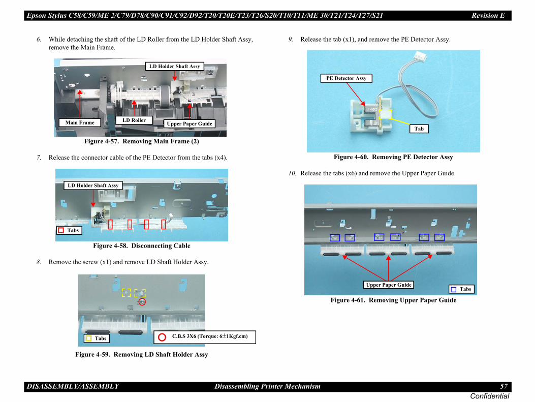
Epson Stylus C58/C59/ME 2/C79/D78/C90/C91/C92/D92/T20/T20E/T23/T26/S20/T10/T11/ME 30/T21/T24/T27/S21 Revision E
D 57Confidential
e the PE Detector Assy.
oving PE Detector Assy
ve the Upper Paper Guide.
ving Upper Paper Guide
Tab
aper GuideTabs
ISASSEMBLY/ASSEMBLY Disassembling Printer Mechanism
6. While detaching the shaft of the LD Roller from the LD Holder Shaft Assy, remove the Main Frame.
Figure 4-57. Removing Main Frame (2)
7. Release the connector cable of the PE Detector from the tabs (x4).
Figure 4-58. Disconnecting Cable
8. Remove the screw (x1) and remove LD Shaft Holder Assy.
Figure 4-59. Removing LD Shaft Holder Assy
9. Release the tab (x1), and remov
Figure 4-60. Rem
10. Release the tabs (x6) and remo
Figure 4-61. Remo
LD Holder Shaft Assy
Upper Paper GuideMain Frame LD Roller
Tabs
LD Holder Shaft Assy
Tabs C.B.S 3X6 (Torque: 6±1Kgf.cm)
PE Detector Assy
Upper P
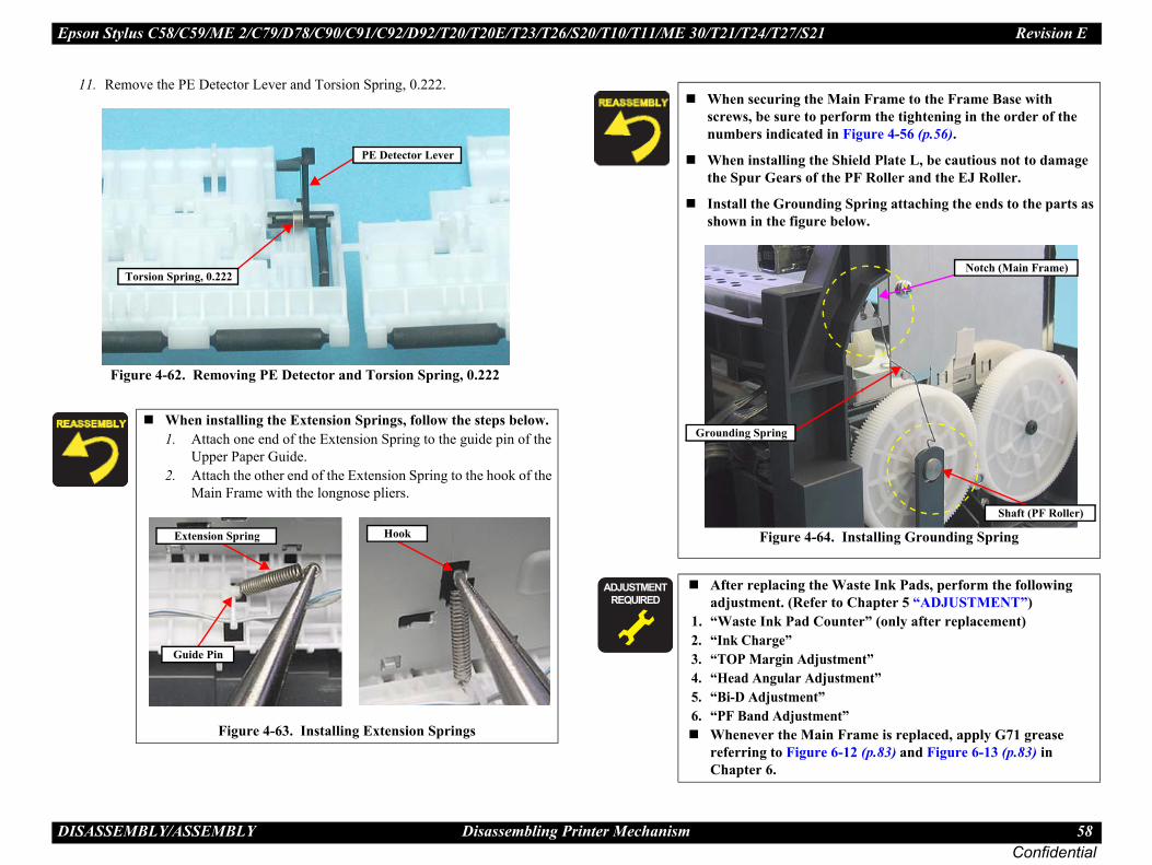
Epson Stylus C58/C59/ME 2/C79/D78/C90/C91/C92/D92/T20/T20E/T23/T26/S20/T10/T11/ME 30/T21/T24/T27/S21 Revision E
D 58Confidential
the Main Frame to the Frame Base with to perform the tightening in the order of the ted in Figure 4-56 (p.56).
the Shield Plate L, be cautious not to damage of the PF Roller and the EJ Roller.
nding Spring attaching the ends to the parts as ure below.
4-64. Installing Grounding Spring
the Waste Ink Pads, perform the following efer to Chapter 5 “ADJUSTMENT”)d Counter” (only after replacement)
djustment” Adjustment”nt”stment”Main Frame is replaced, apply G71 grease ure 6-12 (p.83) and Figure 6-13 (p.83) in
Notch (Main Frame)
Shaft (PF Roller)
ISASSEMBLY/ASSEMBLY Disassembling Printer Mechanism
11. Remove the PE Detector Lever and Torsion Spring, 0.222.
Figure 4-62. Removing PE Detector and Torsion Spring, 0.222
When installing the Extension Springs, follow the steps below.1. Attach one end of the Extension Spring to the guide pin of the
Upper Paper Guide.2. Attach the other end of the Extension Spring to the hook of the
Main Frame with the longnose pliers.
Figure 4-63. Installing Extension Springs
Torsion Spring, 0.222
PE Detector Lever
Hook
Guide Pin
Extension Spring
When securingscrews, be surenumbers indica
When installingthe Spur Gears
Install the Groushown in the fig
Figure
� � � � � �
� � � � �
After replacingadjustment. (R
1. “Waste Ink Pa2. “Ink Charge”3. “TOP Margin A4. “Head Angular5. “Bi-D Adjustme6. “PF Band Adju
Whenever the referring to FigChapter 6.
Grounding Spring
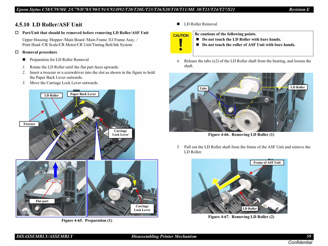
Epson Stylus C58/C59/ME 2/C79/D78/C90/C91/C92/D92/T20/T20E/T23/T26/S20/T10/T11/ME 30/T21/T24/T27/S21 Revision E
D 59Confidential
4.
Roller shaft from the bearing, and loosen the
emoving LD Roller (1)
m the frame of the ASF Unit and remove the
emoving LD Roller (2)
wing points.D Roller with bare hands.ller of ASF Unit with bare hands.
LD Roller
Frame of ASF Unit
LD Roller
ISASSEMBLY/ASSEMBLY Disassembling Printer Mechanism
5.10 LD Roller/ASF UnitPart/Unit that should be removed before removing LD Roller/ASF Unit
Upper Housing /Hopper /Main Board /Main Frame /EJ Frame Assy. / Print Head /CR Scale/CR Motor/CR Unit/Timing Belt/Ink System
Removal procedure
Preparation for LD Roller Removal
1. Rotate the LD Roller until the flat part faces upwards.2. Insert a tweezer or a screwdriver into the slot as shown in the figure to hold
the Paper Back Lever outwards. 3. Move the Carriage Lock Lever outwards.
Figure 4-65. Preparation (1)
LD Roller Removal
4. Release the tabs (x2) of the LDshaft.
Figure 4-66. R
5. Pull out the LD Roller shaft froLD Roller.
Figure 4-67. R
Tweezer
CarriageLock Lever
Flat part
LD Roller Paper Back Lever
CarriageLock Lever
� � � � �Be cautious of the follo
Do not touch the LDo not touch the ro
Tabs

Epson Stylus C58/C59/ME 2/C79/D78/C90/C91/C92/D92/T20/T20E/T23/T26/S20/T10/T11/ME 30/T21/T24/T27/S21 Revision E
D 60Confidential
D Roller as shown below.
e 4-69. Assembling LD Roller (1) pin of the LD Roller Shaft with the positioning h.f the Extension Spring 0.143 to the tab of the LD the tab of the Clutch.ide of the Spur Gear 36.8 to the hole of the Clutch.
e 4-70. Assembling LD Roller (2)
D Roller is replaced, apply G71 grease ure 6-4 (p.81) and Figure 6-5 (p.81) in Chapter
Clutch
Extension Spring 0.143
Spur Gear 36.8
LD Roller Shaft Guide pin
Positioning hole
Clutch
ISASSEMBLY/ASSEMBLY Disassembling Printer Mechanism
ASF Unit Removal
1. Remove the screw (x1) from the side of the Lower Housing.2. Remove the screws (x2), and remove the ASF Unit taking care not to scratch
it with the positioning tab.
Figure 4-68. Removing ASF Unit
ASF Unit
Positioning Tab
Lower Housing
ASF Unit
C.B.P 3X8 (Torque: 6±1Kgf.cm)
Assemble the L
Figur1. Match the guide
hole of the Clutc2. Attach the tips o
Roller shaft and 3. Attach the cam s
Figur
� � � � � �
� � � � �
Whenever the Lreferring to Fig6.
LD Roller
Tabs
LD Roller

Epson Stylus C58/C59/ME 2/C79/D78/C90/C91/C92/D92/T20/T20E/T23/T26/S20/T10/T11/ME 30/T21/T24/T27/S21 Revision E
D 61Confidential
4.
�
e Waste Ink Pads on the section , be sure one on top of another in the order shown in
2. Installing Waste Ink Pads (1)e Waste Ink Pads on the section (B), make ips of induction paper between the and
3. Installing Waste Ink Pads (2)
e Waste Ink Pads, perform the following r to Chapter 5 “ADJUSTMENT”)ounter” (only after replacement)
ustment”justment”
”ent”
Tips of induction paper
ISASSEMBLY/ASSEMBLY Disassembling Printer Mechanism
5.11 Waste Ink PadsPart/Unit that should be removed before removing Waste Ink Pads
Upper Housing /Hopper /Main Board /Main Frame /EJ Frame Assy. / Print Head /CR Scale/CR Motor/CR Unit/Timing Belt/Ink System/Power Supply Board/EJ Roller/ASF Unit
Removal procedure
1. Remove the Waste Ink Pads (x8) from the sections indicated with to of the Frame Base.
Figure 4-71. Removing Waste Ink Pads
� � � �When removing the Waste Ink Pads, be careful not to tear the tip of the induction paper. If it is torn, replace the induction paper.
When installing the Waste Ink Pads, be sure to insert ribs and tabs of the Frame Base into the slots and notches of the pads.When installing in the section (refer to Figure 4-72), be sure to match the positioning tabs and press until it clicks to secure it in the right position.
When installing thto lay the six partsthe figure.
Figure 4-7When installing thsure to insert the t
pads.
Figure 4-7
� � � � � �
� � � � �
After replacing thadjustment. (Refe
1. “Waste Ink Pad C2. “Ink Charge”3. “TOP Margin Adj4. “Head Angular Ad5. “Bi-D Adjustment6. “PF Band Adjustm
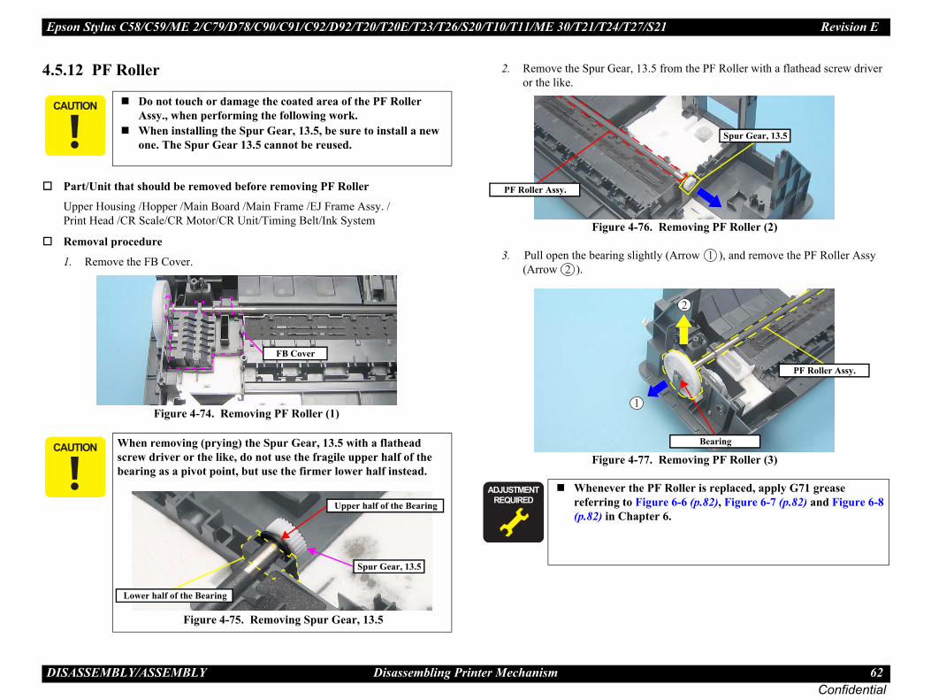
Epson Stylus C58/C59/ME 2/C79/D78/C90/C91/C92/D92/T20/T20E/T23/T26/S20/T10/T11/ME 30/T21/T24/T27/S21 Revision E
D 62Confidential
4. om the PF Roller with a flathead screw driver
emoving PF Roller (2)
(Arrow ), and remove the PF Roller Assy
emoving PF Roller (3)
�
�
oller is replaced, apply G71 grease 6-6 (p.82), Figure 6-7 (p.82) and Figure 6-8 .
Spur Gear, 13.5
Bearing
PF Roller Assy.
ISASSEMBLY/ASSEMBLY Disassembling Printer Mechanism
5.12 PF Roller
Part/Unit that should be removed before removing PF Roller
Upper Housing /Hopper /Main Board /Main Frame /EJ Frame Assy. / Print Head /CR Scale/CR Motor/CR Unit/Timing Belt/Ink System
Removal procedure
1. Remove the FB Cover.
Figure 4-74. Removing PF Roller (1)
2. Remove the Spur Gear, 13.5 fror the like.
Figure 4-76. R
3. <Pull open the bearing slightly (Arrow ).
Figure 4-77. R
� � � �Do not touch or damage the coated area of the PF Roller Assy., when performing the following work.When installing the Spur Gear, 13.5, be sure to install a new one. The Spur Gear 13.5 cannot be reused.
� � � �When removing (prying) the Spur Gear, 13.5 with a flathead screw driver or the like, do not use the fragile upper half of the bearing as a pivot point, but use the firmer lower half instead.
Figure 4-75. Removing Spur Gear, 13.5
FB Cover
Spur Gear, 13.5
Lower half of the Bearing
Upper half of the Bearing
� � � � � �
� � � � �
Whenever the PF Rreferring to Figure(p.82) in Chapter 6
PF Roller Assy.

Epson Stylus C58/C59/ME 2/C79/D78/C90/C91/C92/D92/T20/T20E/T23/T26/S20/T10/T11/ME 30/T21/T24/T27/S21 Revision E
D 63Confidential
4. otor, arrange the cable into the slit and errite core into the positioning hole.
0. Installing the PF Motor
Hook
Slit
ISASSEMBLY/ASSEMBLY Disassembling Printer Mechanism
5.13 PF MotorPart/Unit that should be removed before removing PF Motor
Upper Housing /Hopper /Main Board /Main Frame /EJ Frame Assy. / Print Head /CR Scale /CR Motor /CR Unit /Timing Belt /EJ Roller /PF Roller
Removal procedure
1. Detach the ferrite core from the Main Frame.
Figure 4-78. Removing PF Motor (1)
2. Remove the screws (x3), and remove the PF Motor.
Figure 4-79. Removing PF Motor (2)
Ferrite Core
Main Frame
PF Motor
C.B.S 3X8 (Torque: 6±1Kgf.cm)
When installing the PF Mthe hook, then place the f
Figure 4-8
Ferrite Core
Positioning hole
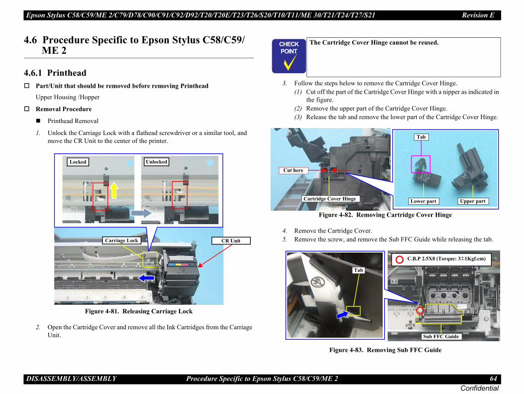
Epson Stylus C58/C59/ME 2/C79/D78/C90/C91/C92/D92/T20/T20E/T23/T26/S20/T10/T11/ME 30/T21/T24/T27/S21 Revision E
D 64Confidential
4.
4.emove the Cartridge Cover Hinge.artridge Cover Hinge with a nipper as indicated in
t of the Cartridge Cover Hinge.move the lower part of the Cartridge Cover Hinge.
oving Cartridge Cover Hinge
er.ove the Sub FFC Guide while releasing the tab.
Removing Sub FFC Guide
r Hinge cannot be reused.
Tab
Lower part Upper part
Sub FFC Guide
C.B.P 2.5X8 (Torque: 3±1Kgf.cm)
ISASSEMBLY/ASSEMBLY Procedure Specific to Epson Stylus C58/C59/ME 2
6 Procedure Specific to Epson Stylus C58/C59/ME 2
6.1 PrintheadPart/Unit that should be removed before removing Printhead
Upper Housing /Hopper
Removal Procedure
Printhead Removal
1. Unlock the Carriage Lock with a flathead screwdriver or a similar tool, and move the CR Unit to the center of the printer.
Figure 4-81. Releasing Carriage Lock
2. Open the Cartridge Cover and remove all the Ink Cartridges from the Carriage Unit.
3. Follow the steps below to r(1) Cut off the part of the C
the figure.(2) Remove the upper par(3) Release the tab and re
Figure 4-82. Rem
4. Remove the Cartridge Cov5. Remove the screw, and rem
Figure 4-83.
Carriage Lock CR Unit
Locked Unlocked
� � � �
� � � �
The Cartridge Cove
Cartridge Cover Hinge
Cut here
Tab

Epson Stylus C58/C59/ME 2/C79/D78/C90/C91/C92/D92/T20/T20E/T23/T26/S20/T10/T11/ME 30/T21/T24/T27/S21 Revision E
D 65Confidential
ecure the Holder Board Assy, and remove the .
emoving Holder Board Assy
ab (2)
Tab (1)
Holder Board Assy
Tab (2)
(1)
it
Tab (2)
CR Unit
ISASSEMBLY/ASSEMBLY Procedure Specific to Epson Stylus C58/C59/ME 2
6. Release the FFC from the tabs.
Figure 4-84. Releasing FFCs from Tabs
7. Disconnect the FFCs (x2) that are connected to the CSIC Board and the CR Encoder Board.
Figure 4-85. Disconnecting Head FFCs
8. Release the tabs (x2) that sHolder Board Assy upward
Figure 4-86. R
Tabs
FFCs
FFCs
Tab (1) T
HolderBoard Assy.
Tab
CR Un

Epson Stylus C58/C59/ME 2/C79/D78/C90/C91/C92/D92/T20/T20E/T23/T26/S20/T10/T11/ME 30/T21/T24/T27/S21 Revision E
D 66Confidential
� the Holder Board Assy, make sure to check if erly installed in the right position. The assy is alled in the wrong position.
n Label is not included in the Cartridge Cover. the Cartridge Cover, order the label
attach the Ink Position Label to the place shown
4-89. Installing Ink Position Label
lacing the Printhead, perform the adjustment er. (Refer to Chapter 5 “ADJUSTMENT”)only after replacement)” (only after replacement)djustment”stment” Adjustment”nt”stment”
Cartridge Cover
is position with right.
ISASSEMBLY/ASSEMBLY Procedure Specific to Epson Stylus C58/C59/ME 2
9. Remove the screws (x3) that secure the Printhead, and lift up the Printhead with a longnose pliers.
Figure 4-87. Removing Printhead (1)
10. Disconnect the Head FFC (x1) from the connector (x1) on the Printhead, and remove the Printhead.
Figure 4-88. Removing Printhead (2)
� � � �Do not touch or damage the nozzles or the ink supply needles of the Printhead.
C.B.P 2.5X8 (Torque: 3±1Kgf.cm)
Head FFC
Printhead
When installingthe assy is proplikely to be inst
The Ink PositioWhen replacingseparately and below.
Figure
� � � � � �
� � � � �
After removing/repin the following ord1. “Ink Charge” (2. “Head ID Input3. “TOP Margin A4. “First Dot Adju5. “Head Angular6. “Bi-D Adjustme7. “PF Band Adju
Ink Position Label
Install the label in thBlack to the

Epson Stylus C58/C59/ME 2/C79/D78/C90/C91/C92/D92/T20/T20E/T23/T26/S20/T10/T11/ME 30/T21/T24/T27/S21 Revision E
D 67Confidential
4.
�
the Waste Ink Pads on the section , be sure arts one on top of another in the order shown
4-91. Installing Waste Ink Pads (1)
the Waste Ink Pads on the section (B), make e tips of induction paper between the and
4-92. Installing Waste Ink Pads (2)
the Waste Ink Pads, perform the following efer to Chapter 5 “ADJUSTMENT”)d Counter” (only after replacement)
djustment” Adjustment”nt”stment”
Tips of induction paper
ISASSEMBLY/ASSEMBLY Procedure Specific to Epson Stylus C58/C59/ME 2
6.2 Waste Ink PadsPart/Unit that should be removed before removing Waste Ink Pads
Upper Housing /Hopper /Main Board /Main Frame /EJ Frame Assy. / Print Head /CR Scale/CR Motor/CR Unit/Timing Belt/Ink System/Power Supply Board/EJ Roller/ASF Unit
Removal procedure
1. Remove the Waste Ink Pads (x7) from the sections indicated with to of the Frame Base.
Figure 4-90. Removing Waste Ink Pads
� � � �When removing the Waste Ink Pads, be careful not to tear the tip of the induction paper. If it is torn, replace the induction paper.
When installing the Waste Ink Pads, be sure to insert ribs and tabs of the Frame Base into the slots and notches of the pads.When installing in the section (refer to Figure 4-91), be sure to match the positioning tabs and press until it clicks to secure it in the right position.
When installingto lay the four pin the figure.
Figure
When installingsure to insert th
pads.
Figure
� � � � � �
� � � � �
After replacingadjustment. (R
1. “Waste Ink Pa2. “Ink Charge”3. “TOP Margin A4. “Head Angular5. “Bi-D Adjustme6. “PF Band Adju

Epson Stylus C58/C59/ME 2/C79/D78/C90/C91/C92/D92/T20/T20E/T23/T26/S20/T10/T11/ME 30/T21/T24/T27/S21 Revision E
D 68Confidential
4.If twa“T"D
Step 2 in “ 4.5.9 Main Frame ” (p.56) to Step 6.gether with other parts.
the Main Frame, treat and place the Main at care while following the next instructions.
to deform the Main Frame.r damage the nozzles or the ink supply needles d when placing the Main Frame.
to stick the grease around the area, especially e grease to come in contact with the Timing result in malfunction of the printer.
to lose the rollers of Paper Guide Upper, and do ollers with bare hands.
ling the Main Frame, basically follow the ackward. But in some points listed below, be the reassembly instructions.to bend or damage the Shield Plate L when in Frame on the Frame Base in Step 5.to damage the Carriage Lock Lever when in Frame on the Frame Base in Step 5. (See r LD Roller Removal (p59)) Extension Springs ” (p.58) and “ Installing ing ” (p.58) in Step 5
the Main Frame in this removal, perform the tment. (Refer to Chapter 5 “ADJUSTMENT”) Frame is reassembled, perform the required
efer to Chapter 6 “MAINTENANCE”)
Place the Main Frame with the back side facing down as shown in the figure.
Figure 4-94. How to place the Main Frame
Main Frame with other parts
ISASSEMBLY/ASSEMBLY The Shortest Way to Remove the Main Frame.
7 The Shortest Way to Remove the Main Frame.he parts to repair is only the parts after the Main Frame is removed, there’s another y to remove the Main Frame together with other parts. (See the following list of arget Parts of this removal” or the parts marked with “*” in Figure 4-2, isassembling Flowchart" (p.37))
Figure 4-93. Removing Main Frame with Other Parts
Removal procedure
1. Remove the “ 4.3.1 Upper Housing ” (p.38).2. Remove the “ 4.5.1 Hopper ” (p.42).3. Disconnect the connector cables of P/S ASSY and PF Motor from CN6, CN8
of the Main Board. (See “ 4.4.1 Main Board ” (p.40))4. Remove the “ 4.5.4 CR Motor ” (p.47).5. Remove the screw from the Shield Plate L. (The plate is not to be removed. In
Epson Stylus C79/D78’s case, see Step1 in “ 4.5.9 Main Frame ” (p.56). In Epson Stylus C58/C59/ME2’s case, see Check Point in “ 4.5.8 EJ Frame Assy/EJ Roller ” (p.54))
6. Follow the same steps from7. Remove the Main Frame to
LD RollerASF UnitInk SystemWaste Ink PadPF RollerPF Motor
Target Parts of this removal
Main BoardCR UnitPrintheadCR ScaleHead FFCPE SensorPaper Guide Upper
Main Frame with other parts
Parts removed together
� � � � �After removingFrame with gre
• Be careful not • Do not touch o
of the Printhea • Be careful not
not to allow thBelt, which can
• Be careful not not touch the r
When reassembremoval steps bsure to refer to
• Be careful not placing the Ma
• Be careful not placing the MaPreparation fo
• See “ InstallingGrounding Spr
� � � � � �
� � � � �
After removingrequired adjusWhen the Mainlubrication. (R

C H A P T E R
Confidential
5DJUSTMENT
A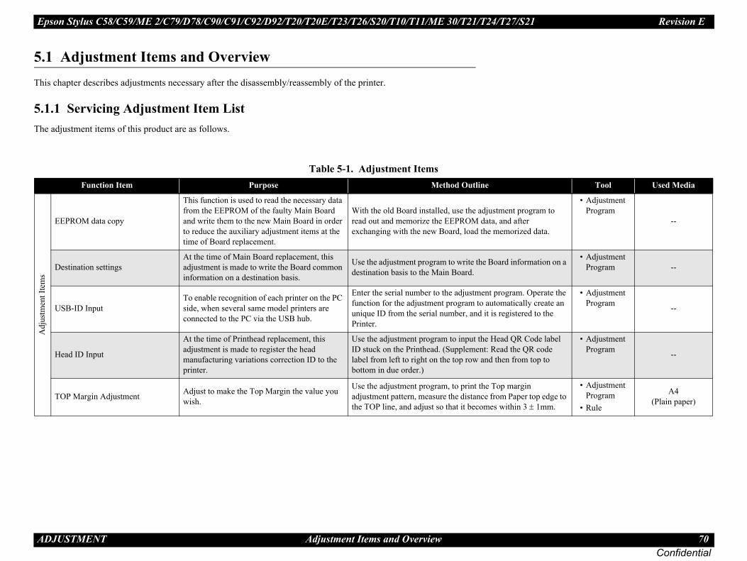
Epson Stylus C58/C59/ME 2/C79/D78/C90/C91/C92/D92/T20/T20E/T23/T26/S20/T10/T11/ME 30/T21/T24/T27/S21 Revision E
A 70Confidential
5.Th
5.Th
Tool Used Media
rogram to ter zed data.
• Adjustment Program
--
ormation on a • Adjustment Program --
. Operate the ally create an red to the
• Adjustment Program --
Code label QR code m top to
• Adjustment Program --
gin er top edge to 3 ± 1mm.
• Adjustment Program
• Rule
A4(Plain paper)
DJUSTMENT Adjustment Items and Overview
1 Adjustment Items and Overviewis chapter describes adjustments necessary after the disassembly/reassembly of the printer.
1.1 Servicing Adjustment Item Liste adjustment items of this product are as follows.
Table 5-1. Adjustment ItemsFunction Item Purpose Method Outline
Adj
ustm
ent I
tem
s
EEPROM data copy
This function is used to read the necessary data from the EEPROM of the faulty Main Board and write them to the new Main Board in order to reduce the auxiliary adjustment items at the time of Board replacement.
With the old Board installed, use the adjustment pread out and memorize the EEPROM data, and afexchanging with the new Board, load the memori
Destination settingsAt the time of Main Board replacement, this adjustment is made to write the Board common information on a destination basis.
Use the adjustment program to write the Board infdestination basis to the Main Board.
USB-ID InputTo enable recognition of each printer on the PC side, when several same model printers are connected to the PC via the USB hub.
Enter the serial number to the adjustment programfunction for the adjustment program to automaticunique ID from the serial number, and it is registePrinter.
Head ID Input
At the time of Printhead replacement, this adjustment is made to register the head manufacturing variations correction ID to the printer.
Use the adjustment program to input the Head QRID stuck on the Printhead. (Supplement: Read thelabel from left to right on the top row and then frobottom in due order.)
TOP Margin Adjustment Adjust to make the Top Margin the value you wish.
Use the adjustment program, to print the Top maradjustment pattern, measure the distance from Papthe TOP line, and adjust so that it becomes within

Epson Stylus C58/C59/ME 2/C79/D78/C90/C91/C92/D92/T20/T20E/T23/T26/S20/T10/T11/ME 30/T21/T24/T27/S21 Revision E
A 71Confidential
nt pattern and • Adjustment Program
A4(Plain paper)
tment pattern, rn with no
/VSD2/
• Adjustment Program
A4(Plain paper)
nt pattern and from the left
• Adjustment Program
• Rule
A4(Glossy paper)
tment pattern, ster the
• Adjustment Program A4
(Plain paper)
m, then appropriate
• Adjustment Program --
Tool Used Media
then execute • Adjustment Program A4 / Letter
(Plain Paper)
e, then • Adjustment
Program A4 / Letter (Plain Paper)
counter by
• Adjustment Program
--
Tool Used Media
DJUSTMENT Adjustment Items and Overview
Adj
ustm
ent I
tem
s
Head angular adjustment Adjust the vertical/horizontal tilt that occur when installing the Head, by the software.
Use the adjustment program to print the adjustmeadjust to meet the standard.
Bi-D adjustmentThis adjustment is made to correct the print timing in the go and return paths in bi-directional printing.
Use the adjustment program to print out the adjusand enter the adjustment value of the printed patteblack/white streaks in the block. Adjustment items are, each dot sizes (ECO/VSD1VSD3) x Colors (Black/Color), total of 8 types.
First dot adjustmentCorrect the print timing by the software to make the start printing position of the main scan direction to the value you wish.
Use the adjustment program to print the adjustmeenter the adjustment value of printed position 5mmedge.
PF Band adjustmentThis adjustment is made to correct the variations of Mechanism, or the paper feeding accuracy.
Use the adjustment program to print out the adjusevaluate the pattern based on the criteria, and regiappropriate adjustment value to the printer.
CR heat protection control
Assuming production variation of the CR Motor and the PS Board, operate this to use the motor capacity to the maximum when the CR Motor generates heat.
Select the replaced parts in the adjustment prograoperate this adjustment to automatically write theadjustment value.
Table 5-2. Maintenance ItemsFunction Item Purpose Method Outline
Mai
nten
ance
Item
s
Head CleaningThis function is used to execute Cleaning efficiently when ink is not delivered from the Head properly, e.g. dot missing.
Use the adjustment program to execute Cleaning, nozzle check printing.
Ink charge
When replacing the Head, this function is used to fill ink in the flow path of the Head in the ASP to make all nozzles printable and stabilize the ink in the Printhead.
Use the adjustment program to execute ink chargexecute nozzle check printing.
Waste ink pad counter read out/Initialization
Initialize the Waste ink pad counter for replaced parts after maintenance error occurred. Also, when counter full is close, pad exchange/counter initialization may be executed to prevent re-fixing.
After exchanging the Waste ink pad, initialize thethe adjustment program.
Table 5-1. Adjustment ItemsFunction Item Purpose Method Outline

Epson Stylus C58/C59/ME 2/C79/D78/C90/C91/C92/D92/T20/T20E/T23/T26/S20/T10/T11/ME 30/T21/T24/T27/S21 Revision E
A 72Confidential
Tool Used Media
t program.
• Adjustment Program
A4 / Letter (Plain paper)
A4 / Letter (Photo Quality Ink Jet Paper)
gram, and • Adjustment Program
t program.
• Adjustment Program
--
DJUSTMENT Adjustment Items and Overview
Table 5-3. Additional FunctionsFunction Item Purpose Method Outline
Add
ition
al F
unct
ions
Print check pattern
Plain PaperThis printing is executed to check whether all adjustment results are normal. Select and execute the functions by the adjustmen
Photo Quality Ink Jet Paper
EEPROM data readout Read the EEPROM data for analysis. Select this function in the exclusive servicing prosave all data of the EEPROM into a file.
Read printerinformation
Waste Ink counter
Read the printer operation information. Select and execute the functions by the adjustmen
Manual CL counter
I/C exchange CL counter
Timer CL counter

Epson Stylus C58/C59/ME 2/C79/D78/C90/C91/C92/D92/T20/T20E/T23/T26/S20/T10/T11/ME 30/T21/T24/T27/S21 Revision E
A 73Confidential
5.Th
No equired” indicates the adjustment item that must be exe sponding part has been removed/replaced. “-” indicates tha are several adjustment items for one exchanging part, exe
8 9 10 11 12
st dotstment
Head Angular
adjustment
Bi-Dadjustment
PF bandadjustment
CR heat protection
control
-- -- -- Required --
-- -- -- Required --
quired Required Required Required --
quired Required Required Required Required
-- -- -- -- --
-- -- -- -- --
quired Required Required Required Required
-- Required Required Required --
-- Required Required Required Required
-- Required Required Required --
-- Required Required Required --
quired Required Required Required --
quired Required Required Required --
quired Required Required -- --
quired Required Required -- Required
quired Required Required Required --
quired Required Required Required Required
quired Required Required Required --
quired Required Required Required --
-- Required Required Required --
-- Required Required -- --
DJUSTMENT Adjustment Items and Overview
1.2 Replacement Part Adjustment Itemse following table indicates the adjustment items for replacement parts.
te: “Required” in this table indicates the adjustment item that must be executed when the corresponding part has been removed/replaced. “Rcuted since the part is related to the corresponding part to be removed/replaced, or the adjustment item that must be executed when the corret no adjustment is required. When you have removed/replaced two or more parts, refer to the corresponding items of all parts. Also, if there cute the adjustment in the priority order mentioned in the table.
Table 5-4. Adjustment ItemsPriority 1 2 3 4 5 6 7
EEPROMdata copy
Destination setting
USB IDinput
Waste inkpad counter Ink charge Head ID
inputTOP marginadjustment
Firadju
HopperRemoval -- -- -- -- -- -- Required
Replacement -- -- -- -- -- -- Required
Main FrameRemoval -- -- -- -- -- -- Required Re
Replacement -- -- -- -- -- -- Required Re
Main Board
Removal -- -- -- -- -- -- --
Replacement Required -- -- -- -- -- --
Replacement(EEPROM Copy NG) -- Required Required
Ink Pads must be replaced
-- Required Required Re
LD roller/ASF unitRemoval -- -- -- -- -- -- Required
Replacement -- -- -- -- -- -- Required
Wasted ink PadsRemoval -- -- -- -- Required -- Required
Replacement -- -- -- Required Required -- Required
PrintheadRemoval -- -- -- -- -- -- Required Re
Replacement -- -- -- -- Required Required Required Re
CR MotorRemoval -- -- -- -- -- -- -- Re
Replacement -- -- -- -- -- -- -- Re
CR unit/Timing BeltRemoval -- -- -- -- -- -- Required Re
Replacement -- -- -- -- -- -- Required Re
Ink System (Pump)Removal -- -- -- -- Required -- Required Re
Replacement -- -- -- -- Required -- Required Re
EJ RollerRemoval -- -- -- -- -- -- --
Replacement -- -- -- -- -- -- --
Adjustment item
Replaced parts

Epson Stylus C58/C59/ME 2/C79/D78/C90/C91/C92/D92/T20/T20E/T23/T26/S20/T10/T11/ME 30/T21/T24/T27/S21 Revision E
A 74Confidential
quired Required Required Required --
quired Required Required Required --
quired Required Required Required --
quired Required Required Required --
-- -- -- -- --
-- -- -- -- Required
-- Required Required Required --
-- Required Required Required --
8 9 10 11 12
st dotstment
Head Angular
adjustment
Bi-Dadjustment
PF bandadjustment
CR heat protection
control
DJUSTMENT Adjustment Items and Overview
PF RollerRemoval -- -- -- -- -- -- Required Re
Replacement -- -- -- -- -- -- Required Re
PF MotorRemoval -- -- -- -- -- -- Required Re
Replacement -- -- -- -- -- -- Required Re
Power Supply BoardRemoval -- -- -- -- -- -- --
Replacement -- -- -- -- -- -- --
EJ Frame AssyRemoval -- -- -- -- -- -- Required
Replacement -- -- -- -- -- -- Required
Table 5-4. Adjustment ItemsPriority 1 2 3 4 5 6 7
EEPROMdata copy
Destination setting
USB IDinput
Waste inkpad counter Ink charge Head ID
inputTOP marginadjustment
Firadju
Adjustment item
Replaced parts

Epson Stylus C58/C59/ME 2/C79/D78/C90/C91/C92/D92/T20/T20E/T23/T26/S20/T10/T11/ME 30/T21/T24/T27/S21 Revision E
AD 75Confidential
5.2ThisFollo
5.2
FOR
Patte
[JudFindof th
[CorIf threpla
92/D92/T20/T20E/T23/T26/S20/T10/
r adjustment Pattern Printing
s of the left and right pattern, and enter the
nter the nearest value and then print the
�
�
s the OK and NG patterns.
1 1 2 3
OK NG
Gap
NGOK
JUSTMENT Adjustment by Using Adjustment Program
Adjustment by Using Adjustment Program section explains how to judge print samples by using the adjustment program. w the instructions of the adjustment program for details of the adjustment methods.
.1 Head angular adjustment
EPSON STYLUS C58/C59/ME2 AND EPSON STYLUS C79/D78
rns are printed as shown below.
Figure 5-1. Head angular adjustment Pattern Printing
gment method] the pattern with least vertical displacement between -3 and 3, and enter the value at pattern.
rective action]e “NG” on both ends are the ones with least vertical displacement, reassemble/ce the Head, and carry out the adjustment again.
FOR EPSON STYLUS C90/C91/CT11/ME 30/T21/T24/T27/S21
Patterns are printed as shown below.
Figure 5-2. Head angula
[Judgment method]Find the pattern with no gaps or overleapvalue of that pattern.
[Corrective action]If an appropriate pattern is not printed, epatterns again.
� � �
� � �
The diagram below shows the OK and NG patterns.
NG -3 -2 -1 0 1 2 3 NG
Sample of Head Angular band pattern :
NG OK
� � � �
� � � �
The diagram below show
--1 -5 -7
NG
Overlap
NG

Epson Stylus C58/C59/ME 2/C79/D78/C90/C91/C92/D92/T20/T20E/T23/T26/S20/T10/T11/ME 30/T21/T24/T27/S21 Revision E
A 76Confidential
5.Pat
[Ju
Mewit
[Co
Withe
ot size (ECO/VSD1/VSD2/VSD3) x color (Black/
adjustment Pattern Printing
rleaps of the left and right pattern, and enter the
ed, enter the nearest value and then print the
hows the OK and NG patterns.
-1
0
1 2 3
-2
OK NG
Gaplap
NGOK
DJUSTMENT Adjustment by Using Adjustment Program
2.2 Top Margin Adjustmentterns are printed as shown below.
Figure 5-3. Top Margin adjustment Pattern Printing
dgment method]
asure the distance from Paper top edge to the adjustment line, and check that it is h in 3±1mm.
rrective action]
th the adjustment program, select adjustment value "+2","+1","-1","-2" and adjust deviation. (Each adjustment value shifts the line by 0.85 mm.)
5.2.3 Bi-D Adjustment8 types of the pattern below, each dColor) are printed.
Figure 5-4. Bi-D
[Judgment method]
Find the pattern with no gaps or ovevalue of that pattern.
[Corrective action]
If an appropriate pattern is not printpatterns again.
Top Pattern Paper
3±1 mm
TOF Line
� � � �
� � � �
The diagram below s
-1 -5 -7
NG
Over
NG
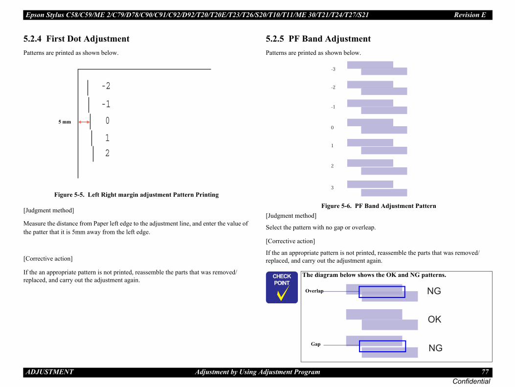
Epson Stylus C58/C59/ME 2/C79/D78/C90/C91/C92/D92/T20/T20E/T23/T26/S20/T10/T11/ME 30/T21/T24/T27/S21 Revision E
A 77Confidential
5.Pat
[Ju
Methe
[Co
If trep
nd Adjustment Pattern
p.
d, reassemble the parts that was removed/ain.
s the OK and NG patterns.
OK
NG
NG
DJUSTMENT Adjustment by Using Adjustment Program
2.4 First Dot Adjustmentterns are printed as shown below.
Figure 5-5. Left Right margin adjustment Pattern Printing
dgment method]
asure the distance from Paper left edge to the adjustment line, and enter the value of patter that it is 5mm away from the left edge.
rrective action]
he an appropriate pattern is not printed, reassemble the parts that was removed/laced, and carry out the adjustment again.
5.2.5 PF Band AdjustmentPatterns are printed as shown below.
Figure 5-6. PF Ba[Judgment method]
Select the pattern with no gap or overlea
[Corrective action]
If the an appropriate pattern is not printereplaced, and carry out the adjustment ag
-2
-1
0
12
5 mm
� � � �
� � � �
The diagram below show
0
-1
-2
-3
1
2
3
Overlap
Gap

C H A P T E R Y
Confidential
6INTENANCE
MA
Epson Stylus C58/C59/ME 2/C79/D78/C90/C91/C92/D92/T20/T20E/T23/T26/S20/T10/T11/ME 30/T21/T24/T27/S21 Revision E
M 79Confidential
6.Th
6.ThPriand
eite line, etc.) has occurred or the printer indicates error is displayed as “Maintenance call error” in to clear the error.
nomenon has occurred, you need to perform the using the printhead cleaning function. This control panel operation, the printer driver utility
is performed by the control panel operation, -by state (the Power LED is lighting), and hold control panel for more than 3 seconds. Then, ence (the Power LED blinks during this
the manual cleaning by the printer driver ing mode is selected. The following is the leaning from the printer driver utility. ment program, refer to .69).
and Epson Stylus C79/D78/C90/C91/C92/D92//ME 30/T21/T24/T27/S21 have four modes for printing, the appropriate cleaning mode is
ed according to various conditions. Therefore anual cleaning varies depending on each mode.
�
AINTENANCE Overview
1 Overview is section provides information to maintain the printer in its optimum condition.
1.1 Cleaning is printer has no mechanical components which require regular cleaning except the nthead. Therefore, when returning the printer to the user, check the following parts perform appropriate cleaning if stain is noticeable.
.
Exterior parts Use a clean soft cloth moistened with water, and wipe off any dirt. If the exterior parts are stained by the ink, use a cloth moistened with neutral detergent to wipe it off.
Inside the printer Use a vacuum cleaner to remove any paper dust.
LD Roller When paper loading function does not operate because friction of the LD roller is lowered by any paper dust, set the adhesive side up of the cleaning sheet (included in the media) to remove any paper dust. Repeat loading the cleaning sheet several times.
6.1.2 Service MaintenancIf any abnormal print (dot missing, whthe “Maintenance request error” (Thisthe STM3), take the following actions
Printhead cleaning When dot missing or banding pheprinthead cleaning operation*1 byfunction can be performed by the and the Adjustment program. In case that the cleaning sequenceconfirm that the printer is in standdown the Error reset button on thethe printer starts the cleaning sequsequence). In case that you select and performutility, the most appropriate cleanprocess to perform the printhead cAs for the operation of the AdjustChapter 5 “ADJUSTMENT” (p *1: Epson Stylus C58/C59/ME 2 T20/T20E/T23/T26/S20/T10/T11manual cleaning, and even duringautomatically selected and performthe ink consumption amount for m
� � � �Never use chemical solvents, such as thinner, benzine, and acetone to clean the exterior parts of the printer like the Housing. These chemicals may deform or deteriorate the components of the printer.Be careful not to damage any components when you clean inside the printer.Do not scratch the coated surface of the PF roller. Use soft brush to wipe off any dusts. Use a soft cloth moistened with alcohol to remove the ink stain.Do not use cleaning sheet included in the media for normal usage. It may damage the coated surface of PF roller. If the adhesive surface of the cleaning sheet is set to the LD roller shaft side and used to clean the LD roller surface, it is no problem. When using compressed air products; such as air duster, for cleaning during repair and maintenance, the use of such products containing flammable gas is prohibited.

Epson Stylus C58/C59/ME 2/C79/D78/C90/C91/C92/D92/T20/T20E/T23/T26/S20/T10/T11/ME 30/T21/T24/T27/S21 Revision E
M 80Confidential
1.
2.
intenance call error) aning operation as well as the printing operation. nthead cleaning operation, the ink is drained to the ount of the waste ink is stored as the waste ink e Main board. Due to this, when the waste ink max 000) of the absorbing capability of the Waste drain rror is indicated on Status monitor 3 as following ter is changed by usage, therefore waste ink max
enance error indication in STM3
rain ink pad and clear the waste ink counter stored unter can be reset only from the Adjustment
ot have the waste ink counter reset function by the ure, refer to Chapter 5 “ADJUSTMENT” (p.69). ste ink counter along with the firmware version, n and nozzle check pattern on the nozzle check nter is closed to its limit, recommend that the
d with new one. This is because the “Maintenance eturning the repaired product to the customer.
AINTENANCE Overview
Select the “EPSON Status Monitor 3” in the printer driver utility, and make sure that the printer is in stand-by state by using the Status monitor 3. If the printer is in stand-by state, the following figure is indicated on the monitor.
Figure 6-1. Status monitor 3 indication
Select the “Head Cleaning” in the printer driver utility, and perform the printhead cleaning. After performing the printhead cleaning operation, print a nozzle check pattern by selecting the “Nozzle Check“. If you repeat the printhead cleaning operation without selecting the “Nozzle Check”, CL1, the weakest cleaning, will be repeated.
Figure 6-2. Head cleaning function in the printer driver utility
Maintenance request error (MaInk is used for the printhead cleWhen the ink is used for the priWaste drain ink pad and the amcounter into the EEPROM on thcounter has reached the limit (9ink pad, the Maintenance call efigure. But waste ink max councounter is not necessarily right.
Figure 6-3. Maint
In this case, replace to new Waste dinto the EEPROM. The waste ink coprogram because this printer dose ncontrol panel SW. As for the procedIn your repair activity, check the waMain board checker program versiopattern printing. If the waste ink couWaste drain ink pad will be replacerequest error” will may occur after r
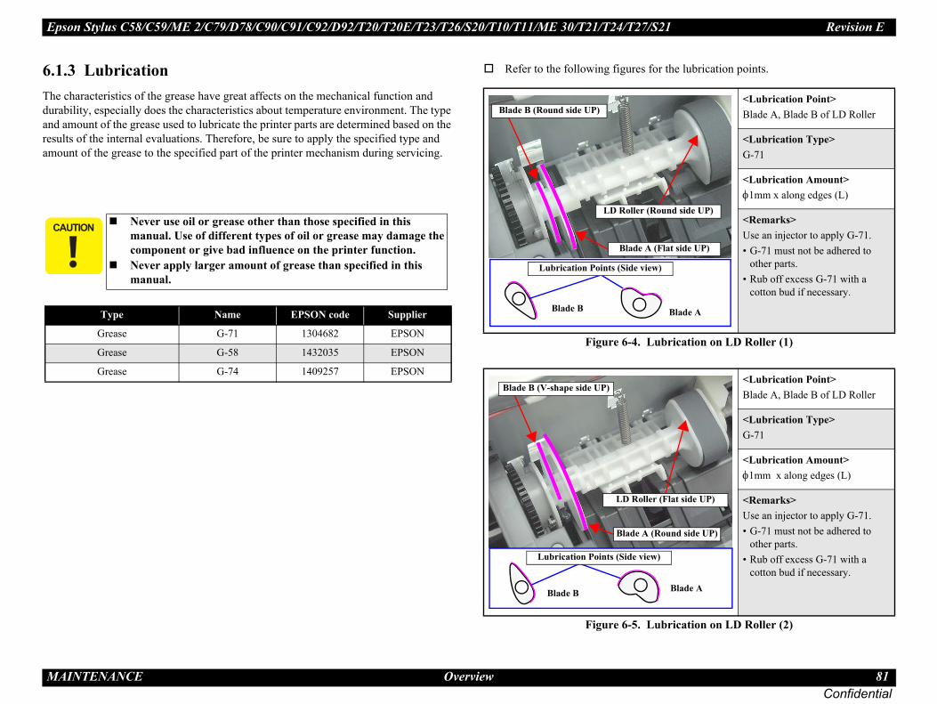
Epson Stylus C58/C59/ME 2/C79/D78/C90/C91/C92/D92/T20/T20E/T23/T26/S20/T10/T11/ME 30/T21/T24/T27/S21 Revision E
M 81Confidential
6.Thdurandresam
or the lubrication points.
ubrication on LD Roller (1)
ubrication on LD Roller (2)
�
<Lubrication Point>Blade A, Blade B of LD Roller
<Lubrication Type>G-71
<Lubrication Amount>φ1mm x along edges (L)
<Remarks>Use an injector to apply G-71.• G-71 must not be adhered to
other parts.• Rub off excess G-71 with a
cotton bud if necessary.
<Lubrication Point>Blade A, Blade B of LD Roller
<Lubrication Type>G-71
<Lubrication Amount>φ1mm x along edges (L)
<Remarks>Use an injector to apply G-71.• G-71 must not be adhered to
other parts.• Rub off excess G-71 with a
cotton bud if necessary.
(Flat side UP)
ound side UP)
Blade A
w)
(Round side UP)
r (Flat side UP)
Blade A
)
AINTENANCE Overview
1.3 Lubrication e characteristics of the grease have great affects on the mechanical function and ability, especially does the characteristics about temperature environment. The type amount of the grease used to lubricate the printer parts are determined based on the
ults of the internal evaluations. Therefore, be sure to apply the specified type and ount of the grease to the specified part of the printer mechanism during servicing.
Refer to the following figures f
Figure 6-4. L
Figure 6-5. L
� � � �Never use oil or grease other than those specified in this manual. Use of different types of oil or grease may damage the component or give bad influence on the printer function.Never apply larger amount of grease than specified in this manual.
Type Name EPSON code Supplier
Grease G-71 1304682 EPSON
Grease G-58 1432035 EPSON
Grease G-74 1409257 EPSON
Blade A
LD Roller (R
Blade B (Round side UP)
Blade B
Lubrication Points (Side vie
Blade B (V-shape side UP)
Blade A
LD Rolle
Blade B
Lubrication Points (Side view

Epson Stylus C58/C59/ME 2/C79/D78/C90/C91/C92/D92/T20/T20E/T23/T26/S20/T10/T11/ME 30/T21/T24/T27/S21 Revision E
M 82Confidential
brication on PF Roller
rication on EJ Roller (1)
2 Only.
<Lubrication Point>Shaft and Groove of PF Roller
<Lubrication Type>G-71
<Lubrication Point>φ1 mm x around shaft x 2
<Remarks>Use an injector to apply G-71.• G-71 must not be adhered to
other parts.• Rub off excess G-71 with a
cotton bud if necessary.
<Lubrication Point>(1) Teeth of Spur Gear of EJ Roller*(2) Shaft of Spur Gear of EJ Roller
<Lubrication Type>(1) G-58*(2) G-71
<Lubrication Amount>(1) φ1 mm x 60 mm*(2) φ1 mm x around shaft
<Remarks>Use an injector to apply G-58* and G-71.• G-71 must not be adhered to
other parts.• Rub off excess G-71 with a
cotton bud if necessary.
PF Roller
ion Points
Point(2)
Roller
AINTENANCE Overview
Figure 6-6. Lubrication on PF Roller Bearing (1)
Figure 6-7. Lubrication on PF Roller Bearing (2)
Figure 6-8. Lu
Figure 6-9. Lub
Note * : Epson Stylus C90/C91/C92/D9
<Lubrication Point>Bearing A of Lower Housing (for PF Roller)
<Lubrication Type>G-71
<Lubrication Amount>φ1 mm x along inner edge (L)
<Remarks>Use an injector to apply G-71.• G-71 must not be adhered to
other parts.• Rub off excess G-71 with a
cotton bud if necessary.
<Lubrication Point>Bearing B, C of Lower Housing (for PF Roller)
<Lubrication Type>G-71
<Lubrication Amount>φ1 mm x along inner edges (L)
<Remarks>Use an injector to apply G-71.• G-71 must not be adhered to
other parts.• Rub off excess G-71 with a
cotton bud if necessary.
Lubrication Point
Bearing A
Lower Housing
Bearing C
Bearing BLubrication Point
Lubrication Point
Spur Gear
Lubricat
Lubrication
Spur GearEJ
Lubrication Point(1)
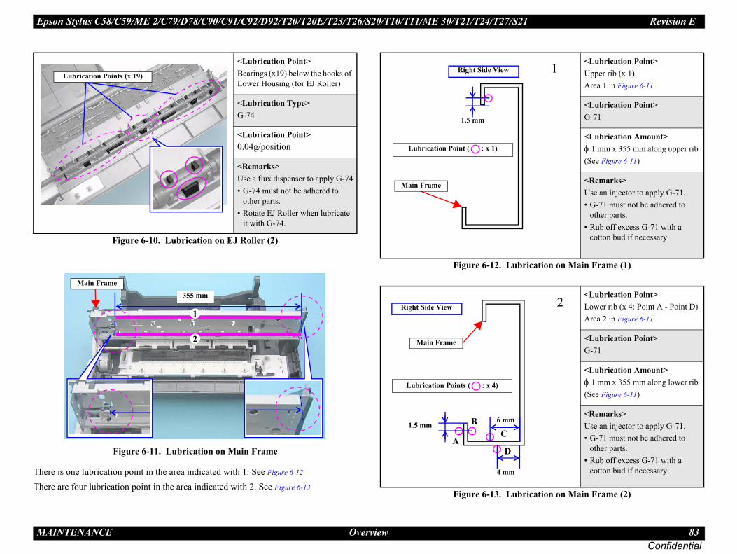
Epson Stylus C58/C59/ME 2/C79/D78/C90/C91/C92/D92/T20/T20E/T23/T26/S20/T10/T11/ME 30/T21/T24/T27/S21 Revision E
M 83Confidential
ThTh
ubrication on Main Frame (1)
ubrication on Main Frame (2)
<Lubrication Point>Upper rib (x 1) Area 1 in Figure 6-11
<Lubrication Point>G-71
<Lubrication Amount>φ 1 mm x 355 mm along upper rib (See Figure 6-11)
<Remarks>Use an injector to apply G-71.• G-71 must not be adhered to
other parts.• Rub off excess G-71 with a
cotton bud if necessary.
<Lubrication Point>Lower rib (x 4: Point A - Point D) Area 2 in Figure 6-11
<Lubrication Point>G-71
<Lubrication Amount>φ 1 mm x 355 mm along lower rib (See Figure 6-11)
<Remarks>Use an injector to apply G-71.• G-71 must not be adhered to
other parts.• Rub off excess G-71 with a
cotton bud if necessary.
1
2
AINTENANCE Overview
Figure 6-10. Lubrication on EJ Roller (2)
Figure 6-11. Lubrication on Main Frame
ere is one lubrication point in the area indicated with 1. See Figure 6-12
ere are four lubrication point in the area indicated with 2. See Figure 6-13
Figure 6-12. L
Figure 6-13. L
<Lubrication Point>Bearings (x19) below the hooks of Lower Housing (for EJ Roller)
<Lubrication Type>G-74
<Lubrication Point>0.04g/position
<Remarks>Use a flux dispenser to apply G-74• G-74 must not be adhered to
other parts.• Rotate EJ Roller when lubricate
it with G-74.
Lubrication Points (x 19)
355 mm
2
1
Main Frame
1.5 mm
Main Frame
Right Side View
Lubrication Point ( : x 1)
1.5 mm
4 mm
AD
Lubrication Points ( : x 4)
Right Side View
Main Frame
6 mmBC

C H A P T E R
Confidential
7APPENDIX

Epson Stylus C58/C59/ME 2/C79/D78/C90/C91/C92/D92/T20/T20E/T23/T26/S20/T10/T11/ME 30/T21/T24/T27/S21 Revision E
A 85Confidential
7.ThSP
PPENDIX Exploded Diagram / Parts List
1 Exploded Diagram / Parts Listis manual does not provide exploded diagrams or parts list. For the information, see I (Service Parts Information).
Top Related