


Languages
Pages
Legal


PS3000 Weighing Indicator
USER GUIDE
Edition: 08-06-2012

Safety Instruction
WARNING
Calibration, inspection, and maintenance of the indicator must be
performed by a qualified technician.
WARNING
The indicator can be damaged by static
electricity and should be considered sensitive
equipment. Remove power during electrical
connections. Touching internal components by
hand is prohibited.
INDEX
Section 1. Instruction ............................................................... 3
1.1 Battery Instruction (Optional) ........................................................................ 3
Section 2. Installation and Calibration .................................... 4
2.1 Power Supply ................................................................................................. 4
2.2 Connecting Load Cell and Indicator .............................................................. 4
Section 3. Operation ................................................................. 5
3.3 Zero operation ................................................................................................ 7
3.4 Tare operation ................................................................................................. 7
3.5 Accumulation operation ................................................................................. 7
3.6 Print and Print Formatting .............................................................................. 8
Section 4. Calibration and Parameters ................................... 9
4.1 Enter Calibration ............................................................................................ 9
4.2 Calibration Procedure................................................................................... 10
4.3 Parameter Settings ........................................................................................ 11
Section 5. Error Codes ........................................................... 15
3
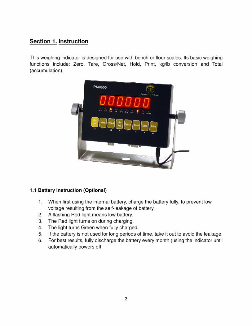
Section 1. Instruction
This weighing indicator is designed for use with bench or floor scales. Its basic weighing
functions include: Zero, Tare, Gross/Net, Hold, Print, kg/lb conversion and Total
(accumulation).
1.1 Battery Instruction (Optional)
1. When first using the internal battery, charge the battery fully, to prevent low
voltage resulting from the self-leakage of battery.
2. A flashing Red light means low battery.
3. The Red light turns on during charging.
4. The light turns Green when fully charged.
5. If the battery is not used for long periods of time, take it out to avoid the leakage.
6. For best results, fully discharge the battery every month (using the indicator until
automatically powers off.
4
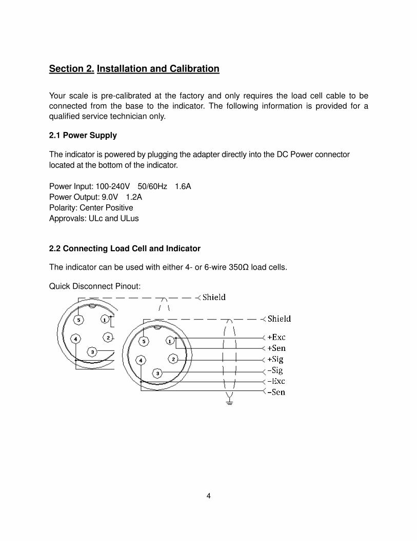
Section 2. Installation and Calibration
Your scale is pre-calibrated at the factory and only requires the load cell cable to be
connected from the base to the indicator. The following information is provided for a
qualified service technician only.
2.1 Power Supply
The indicator is powered by plugging the adapter directly into the DC Power connector
located at the bottom of the indicator.
Power Input: 100-240V 50/60Hz 1.6A
Power Output: 9.0V 1.2A
Polarity: Center Positive
Approvals: ULc and ULus
2.2 Connecting Load Cell and Indicator
The indicator can be used with either 4- or 6-wire 350Ω load cells. Quick Disconnect Pinout:
5
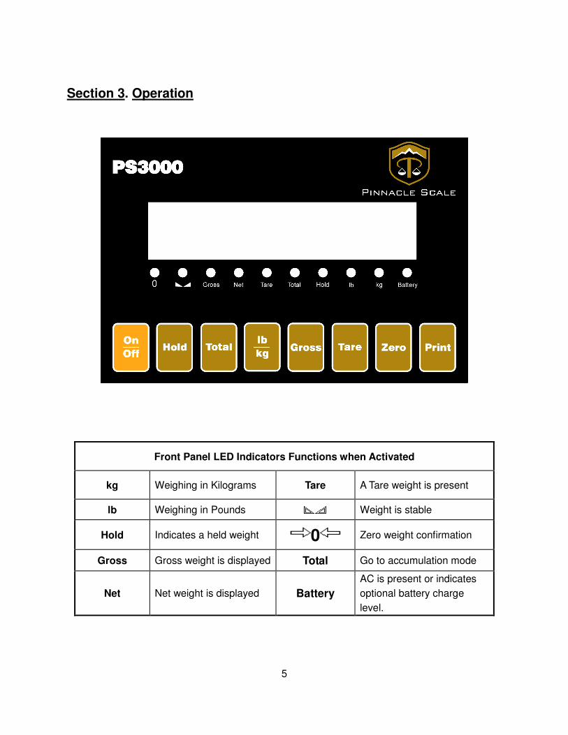
Section 3. Operation
Front Panel LED Indicators Functions when Activated
kg Weighing in Kilograms Tare A Tare weight is present
lb Weighing in Pounds Weight is stable
Hold Indicates a held weight 0 Zero weight confirmation
Gross Gross weight is displayed Total Go to accumulation mode
Net Net weight is displayed Battery
AC is present or indicates
optional battery charge
level.

6
Function
Press to print current weight.
Zero the displayed weight.
Press to tare any non-negative displayed weight. The
indicator automatically switches to NET mode.
When in Net mode, press to clear the tare weight in
memory. The indicator automatically switches to Gross
mode.
When in Net mode, press to display the gross weight.
The displayed weight will automatically switch back to
Net mode after three seconds.
Toggles between lb and kg units.
Holds the most current weight value on the display until
pressed again. (see C11 for settings)
1. Accumulation
2. Works together with Print to perform the accumulation
function and check the accumulation result
Turns the indicator On and Off.
Hold for 2 seconds to power Off.

7
3.3 Zero operation
1. Initial zero – When the indicator powers up it will automatically zero out 10% of
the scale capacity. If this is not desired, change parameter C21 to the desired
setting.
2. Manual Zero – You can zero up to 100% of the scale capacity by pressing
ZERO.
3.4 Tare operation
Press TARE key, the displayed weight is tared. The indicator then displays a zero
Net weight and activates the NET and TARE status lights. In Net mode, press TARE
key to clear the tare weight. The indicator will then enter the Gross mode.
3.5 Accumulation operation
Place the item on the scale and wait until stable, Press TOTAL to enter accumulation
mode, the TOTAL indicator will turn on and the display will show the count ‘n001’to
confirm the item was accumulated. Remove the item from the platform and allow the
scale to return to zero. Place the second item on the platform. When the weight is stable
press TOTAL, ‘n002’ is displayed. Repeat until complete. You can accumulate a
maximum of 999 items.
Display the accumulated weight --- Press and hold the PRINT key; then press the TOTAL key,
display ‘n***’, to display the counter value and then the total weight. There are 8 digits
in total. It will show the first 4 digits then the last 4 digits. For example, the first 4 digits
is ‘0012’, and the last 4 digits is ’34.56’. This means the actual weight is 1234.56
EXIT the accumulation function --- When the indicator shows the last 4 digits, Press and hold
TOTAL, the indicator will show ‘clr n’.
To exit without clearing the accumulator: Press PRINT.
To exit and clear the accumulator: Press ZERO and ‘clr y’ will be displayed. Then
Press PRINT.

8
3.6 Print and Print Formatting
When the weight is stable, pressing PRINT will print the displayed weight. Note:
When printing in tare mode, if the weight is negative, it will not print. Set C30 for
the desired date format.
Tare mode Gross mode
Date: XX.XX.XX Date: XX.XX.XX
Time: XX:XX:XX Time: XX:XX:XX
NET XX.X kg GROSS XXX.X kg
TARE XX.X kg
GROSS XXX.X kg

9
Section 4. Calibration and Parameters
The following information is provided for a qualified service technicians only.
Calibration of the scale requires the use of certified weights. Any alteration of the
settings and/or calibration may require a service call by a certified technician that is not
covered under the warranty.
4.1 Enter Calibration
1. Press and hold PRINT, then press HOLD to enter calibration.
2. If this procedure does not enter calibration, remove the rear cover and locate
the switch on the lower left of the circuit board labeled MARK. This switch
must be in the ON position to enter calibration. Once turned on, repeat step 1
above.
NOTE: If the indicator has an NTEP seal and a lead and wire seal, an authorized
technician must perform this work so the legal for trade status with local weights and
measures authorities is not affected.
Button Calibration
Function
Description of Function
PRINT ENTER
Accept parameter value and scroll to next
parameter. Also (where applicable) moves to the
next value within a single parameter.
ZERO UP Change parameter value
TARE DOWN Change parameter value
HOLD BACK Scroll to previous parameter
LB/KG
GROSS
LEFT
RIGHT
Use to select parameter digit (C##, C#_, C_#).
Scroll digit values using Up and Down arrows.
Press Enter to advance to that parameter.
COUNT Exit calibration and save changes
ON/OFF POWER
10
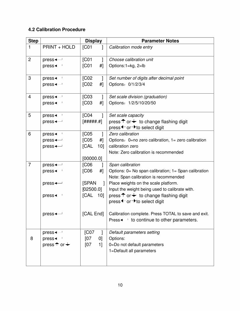
4.2 Calibration Procedure
Step Display Parameter Notes
1 PRINT + HOLD [C01 ] Calibration mode entry
2 press
press
[C01 ]
[C01 #]
Choose calibration unit
Options:1=kg, 2=lb
3 press
press
[C02 ]
[C02 #]
Set number of digits after decimal point
Options:0/1/2/3/4
4 press
press
[C03 ]
[C03 #]
Set scale division (graduation)
Options:1/2/5/10/20/50
5 press
press
[C04 ]
[#####.#]
Set scale capacity
press or to change flashing digit
press or to select digit
6 press
press
press
[C05 ]
[C05 #]
[CAL 10]
[00000.0]
Zero calibration
Options:0=no zero calibration, 1= zero calibration
calibration zero
Note: Zero calibration is recommended
7 press
press
press
press
press
[C06 ]
[C06 #]
[SPAN ]
[02500.0]
[CAL 10]
[CAL End]
Span calibration
Options: 0= No span calibration; 1= Span calibration
Note: Span calibration is recommended
Place weights on the scale platform.
Input the weight being used to calibrate with.
press or to change flashing digit
press or to select digit
Calibration complete. Press TOTAL to save and exit.
Press to continue to other parameters.
8
press
press
press or
[C07 ]
[07 0]
[07 1]
Default parameters setting
Options:
0=Do not default parameters
1=Default all parameters
11
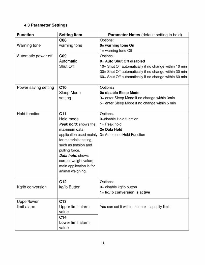
4.3 Parameter Settings
Function Setting Item Parameter Notes (default setting in bold)
Warning tone
C08
warning tone
Options:
0= warning tone On
1= warning tone Off
Automatic power off C09
Automatic
Shut Off
Options:
0= Auto Shut Off disabled
10= Shut Off automatically if no change within 10 min
30= Shut Off automatically if no change within 30 min
60= Shut Off automatically if no change within 60 min
Power saving setting C10
Sleep Mode
setting
Options:
0= disable Sleep Mode
3= enter Sleep Mode if no change within 3min
5= enter Sleep Mode if no change within 5 min
Hold function C11
Hold mode
Peak hold: shows the
maximum data;
application used mainly
for materials testing,
such as tension and
pulling force.
Data hold: shows
current weight value;
main application is for
animal weighing.
Options:
0=disable Hold function
1= Peak hold
2= Data Hold
3= Automatic Hold Function
Kg/lb conversion
C12
kg/lb Button
Options:
0= disable kg/lb button
1= kg/lb conversion is active
Upper/lower
limit alarm
C13
Upper limit alarm
value
You can set it within the max. capacity limit
C14
Lower limit alarm
value

12
A/D Raw Display C15
Displays the A/D raw count reading
Date and time C16
Date
In C16 you can set the date, from left to right:
year/month/day
C17
Time
In C17 you can set the time from left to right:
hour/min./sec.
Communication
setting
C18
Serial interface data
output method
Options:
0= Disable serial interface data output
1= Continuous sending for optional remote display
2= Printer setting
3= PC command request method
4= PC continuous format
5= PC/optional remote display continuous format
C19
Baud rate
Options:
0= 1200 / 1=2400 / 2=4800 / 3=9600
Zero range C20
Manual zero range
(Zero button press)
Options:
0= Disable manual zero setting
1= ±1% max capacity
2= ±2% max capacity
4= ±4% max capacity
10= ±10% max capacity
20= ±20% max capacity
100= ±100% max capacity
C21
Initial zero range
(zero range during
indicator power up
sequence)
Options:
0= no initial zero setting
1= ±1% max capacity
2= ±2% max capacity
5= ±5% max capacity
10= ±10% max capacity
Zero tracking
C22
Automatic zero
tracking range
Options:
0= close zero tracking
0.5=±0.5d
1.0= ±1.0d
2.0= ±2.0d
3.0= ±3.0d
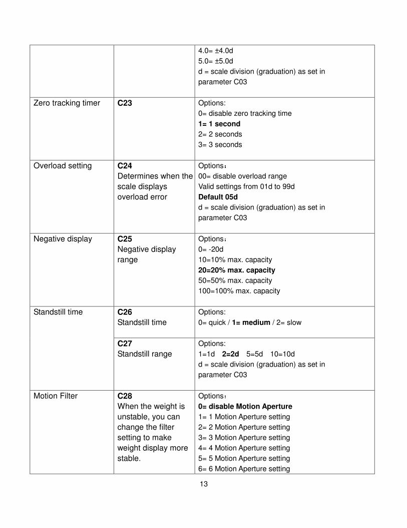
13
4.0= ±4.0d
5.0= ±5.0d
d = scale division (graduation) as set in
parameter C03
Zero tracking timer
C23
Options:
0= disable zero tracking time
1= 1 second
2= 2 seconds
3= 3 seconds
Overload setting C24
Determines when the
scale displays
overload error
Options:
00= disable overload range
Valid settings from 01d to 99d
Default 05d
d = scale division (graduation) as set in
parameter C03
Negative display C25
Negative display
range
Options:
0= -20d
10=10% max. capacity
20=20% max. capacity
50=50% max. capacity
100=100% max. capacity
Standstill time C26
Standstill time
Options:
0= quick / 1= medium / 2= slow
C27
Standstill range
Options:
1=1d 2=2d 5=5d 10=10d
d = scale division (graduation) as set in
parameter C03
Motion Filter C28
When the weight is
unstable, you can
change the filter
setting to make
weight display more
stable.
Options:
0= disable Motion Aperture
1= 1 Motion Aperture setting
2= 2 Motion Aperture setting
3= 3 Motion Aperture setting
4= 4 Motion Aperture setting
5= 5 Motion Aperture setting
6= 6 Motion Aperture setting
14
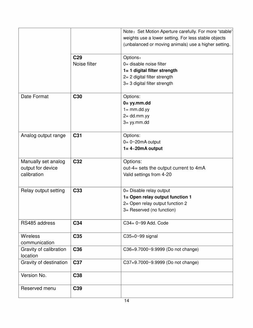
Note:Set Motion Aperture carefully. For more “stable”
weights use a lower setting. For less stable objects
(unbalanced or moving animals) use a higher setting.
C29
Noise filter
Options:
0= disable noise filter
1= 1 digital filter strength
2= 2 digital filter strength
3= 3 digital filter strength
Date Format
C30
Options:
0= yy.mm.dd
1= mm.dd.yy
2= dd.mm.yy
3= yy.mm.dd
Analog output range C31
Options:
0= 0~20mA output
1= 4~20mA output
Manually set analog
output for device
calibration
C32
Options:
out-4= sets the output current to 4mA
Valid settings from 4-20
Relay output setting C33
0= Disable relay output
1= Open relay output function 1
2= Open relay output function 2
3= Reserved (no function)
RS485 address C34
C34= 0~99 Add. Code
Wireless
communication
C35 C35=0~99 signal
Gravity of calibration
location
C36 C36=9.7000~9.9999 (Do not change)
Gravity of destination C37 C37=9.7000~9.9999 (Do not change)
Version No. C38
Reserved menu C39
15
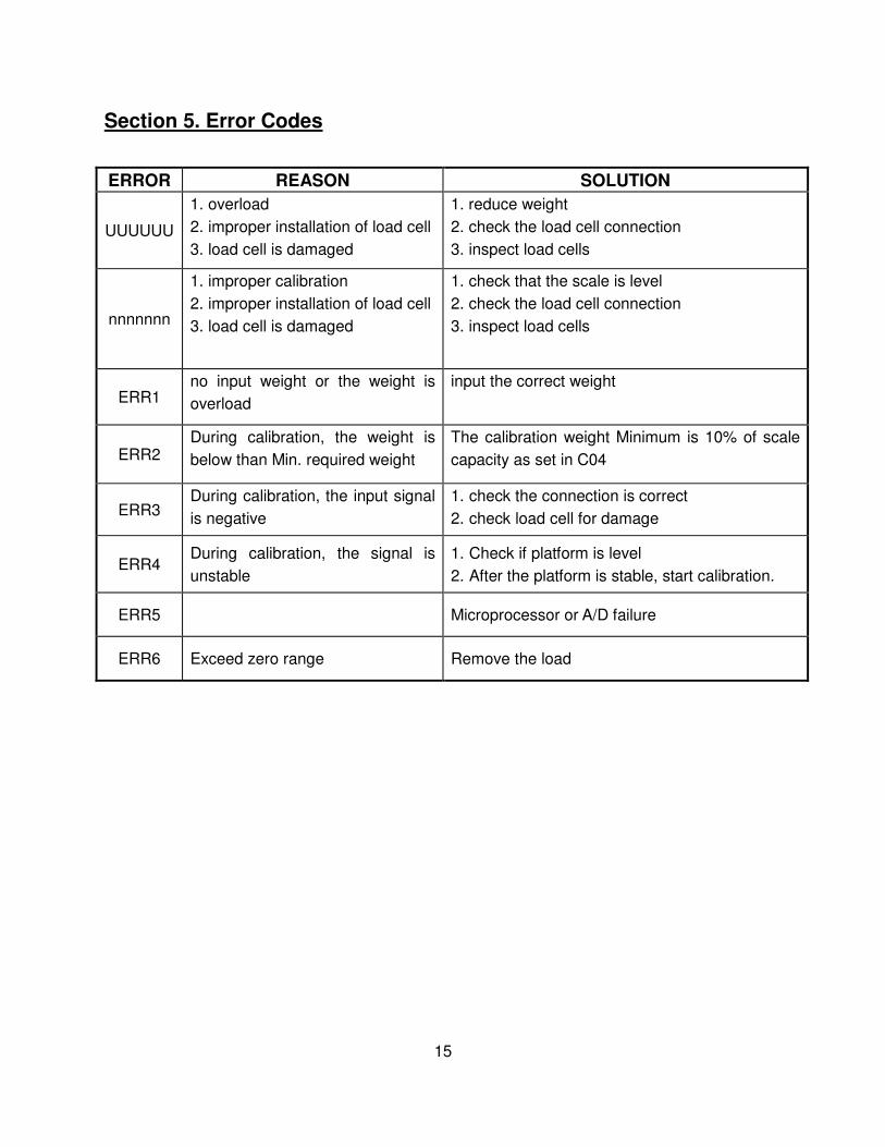
Section 5. Error Codes
ERROR REASON SOLUTION
UUUUUU
1. overload
2. improper installation of load cell
3. load cell is damaged
1. reduce weight
2. check the load cell connection
3. inspect load cells
nnnnnnn
1. improper calibration
2. improper installation of load cell
3. load cell is damaged
1. check that the scale is level
2. check the load cell connection
3. inspect load cells
ERR1 no input weight or the weight is
overload
input the correct weight
ERR2 During calibration, the weight is
below than Min. required weight
The calibration weight Minimum is 10% of scale
capacity as set in C04
ERR3 During calibration, the input signal
is negative
1. check the connection is correct
2. check load cell for damage
ERR4 During calibration, the signal is
unstable
1. Check if platform is level
2. After the platform is stable, start calibration.
ERR5 Microprocessor or A/D failure
ERR6 Exceed zero range Remove the load
Top Related