


Languages
Pages
Legal


Heavy Lifts in Deep Water Subsea 7 Experience
in NW Australia
9th April 2014
Ryan Epstein, Marin Abélanet
(Paul van Amsterdam)
2Page 10.12.10
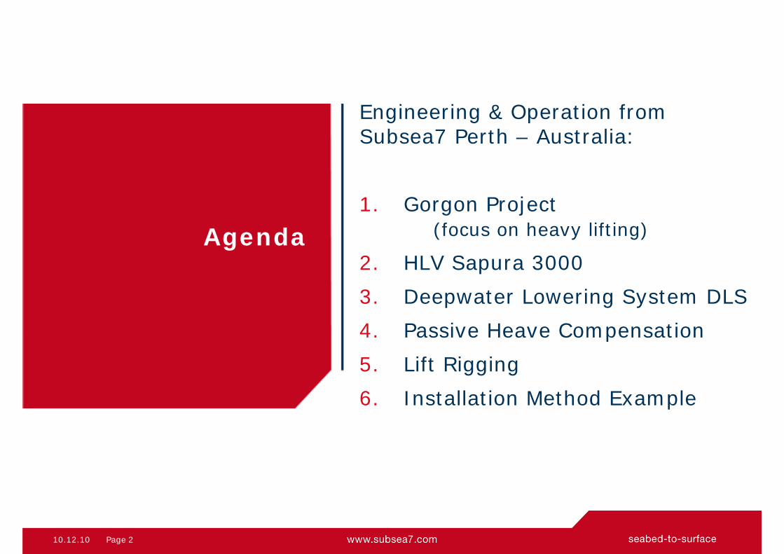
Engineering & Operation from Subsea7 Perth – Australia:
1. Gorgon Project (focus on heavy lifting)
2. HLV Sapura 30003. Deepwater Lowering System DLS4. Passive Heave Compensation5. Lift Rigging6. Installation Method Example
Agenda
10.12.10 3Page
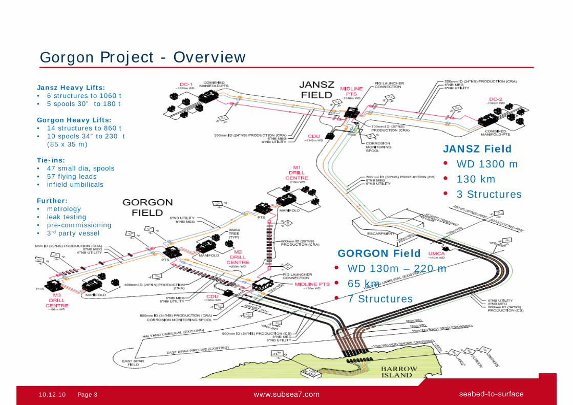
Jansz Heavy Lifts:• 6 structures to 1060 t• 5 spools 30” to 180 t
Gorgon Heavy Lifts:• 14 structures to 860 t• 10 spools 34” to 230 t
(85 x 35 m)
Tie-ins:• 47 small dia, spools• 57 flying leads• infield umbilicals
Further:• metrology• leak testing• pre-commissioning• 3rd party vessel
Gorgon Project - Overview
JANSZ Field• WD 1300 m• 130 km• 3 Structures
GORGON Field• WD 130m – 220 m• 65 km• 7 Structures

10.12.10 4Page
Project : Gorgon Heavy-Lift & Tie-ins
Operator : Chevron Australia (47.3%) Joint Venture : ExxonMobil (25 %t), Shell (25%),
Osaka Gas (1.25%), Tokyo Gas (1%)and Chubu Electric Power (0.417 %)
Field Location : Australian North West Shelf Water Depth : 130-1350m
Contract Award : July 2011 Installation : January 2014 - now
Vessels : Rockwater 2: Sapura 3000: Skandi Acergy: 3rd Party Vessel
Gorgon Project – Overview

10.12.10 5Page
Gorgon - Heavy Lift Structures
Foundations to be installed:• Mudmat type
- up to 938 t- up to 41 m x 32 m
• Suction pile type- up to 474 t- Up to 27 m x 19 m
Manifold / PTS modules to be installed:• Manifold modules
- up to 637 t- up to 19 m x 23 m x 6.5 m
• PTS modules- up to 1186 t- up to 25 m x 25 m x 8 m
Weight in air, incl. rigging (spreaders)
Challenge:- Big, heavy, and deep.- How to install to depth ?

10.12.10 6Page
HLV Heavy Lift Vessel - Sapura 3000
• Sapura 3000 (SapuraAcergy)
• DP 2
• Main Crane (Huisman HLMC)
Main (3000 Sht)– SWL 1600 t @ 37 m, Hs = 1,5 m– Main block does not go subsea– No heave compensation
Aux. (800 Sht)– 725 t @ 53 m, Hs = 1,5 m– 526 t @ 53 m, Hs = 2 m– Down to 250 m waterdepth
Whip– 115 t @ up to 83 m, Hs = 2 m
• 2 x 40 t Deck Crane
• 2 x WROVs

10.12.10 7Page
Lowering Systems Considered
Analysed:
• Lift-off from CB by crane main hoist
and next:
• Outrigger with 27 pennants @ 50 m
• Combine aux. hoist and A&R winch (2500 m - 370 t)
• External winch routed via mast crane
• External overboarding winches DLS

10.12.10 8Page
DLS Deepwater Lowering System - Handover
Arrangement:
• 2 storage winches e.a. 6000 m, c/w level wind• 2 traction winches, e.a. 190 t• sheaves• 1 Deepwater Lowering Beam
• each winch in 4-falls• low rotating wire 78 mm
Deepwater Lowering System (DLS)
10.12.10 9Page
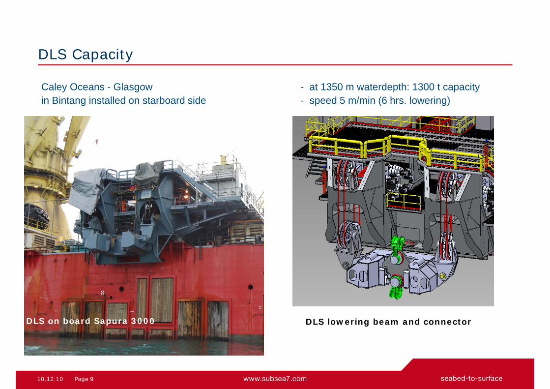
DLS Capacity
DLS on board Sapura 3000 DLS lowering beam and connector
Caley Oceans - Glasgow - at 1350 m waterdepth: 1300 t capacityin Bintang installed on starboard side - speed 5 m/min (6 hrs. lowering)

10.12.10 10Page
Passive Heave Compensator – Crane Master
Used for:• Lift-off from CB• Splash zone• Landing
Particularity:• Used for all 20 lifts: 150 t – 1200 t• Stiffness can be modified:
automatic at 750 m WT, or by ROV
Single Unit:• SWL: 700 t• stroke 4.5 m (pin to pin 6.38 m)• Weight: 40 t (incl. shackles)
Double Unit: (made-up from 2 singles)• SWL: 1400 t• Weight: 100 t (incl. plates, swivel, etc.)

10.12.10 11Page
Upper Rigging:• Steel wire ropes• DLS Connector • Crane Master
Lift Rigging
Connected to lowering beamvia Connector
Lower Rigging:• synthetic slings (for easy
handling and protection) • spreader bars• craddle supports

10.12.10 12Page
Heavy Lift Structure - Installation Criteria
Installation parameters: Operations:
• Positioning accuracy: Heading +/- 1.5° better than 1.0° Position tolerance 2.5 m radius better than 1.0 m
• Max landing velocity: 0.2 to 0.3 m/s observed ‘zero’ movements
10.12.10 13Page
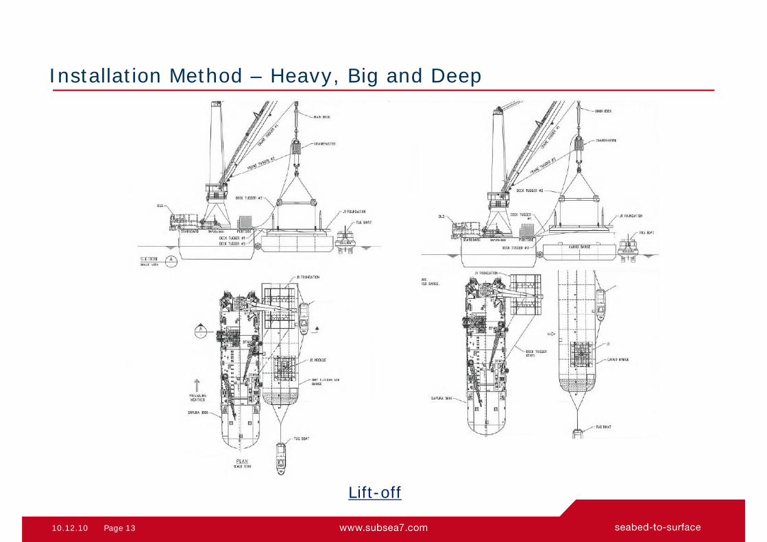
Installation Method – Heavy, Big and Deep
Lift-off
10.12.10 14Page
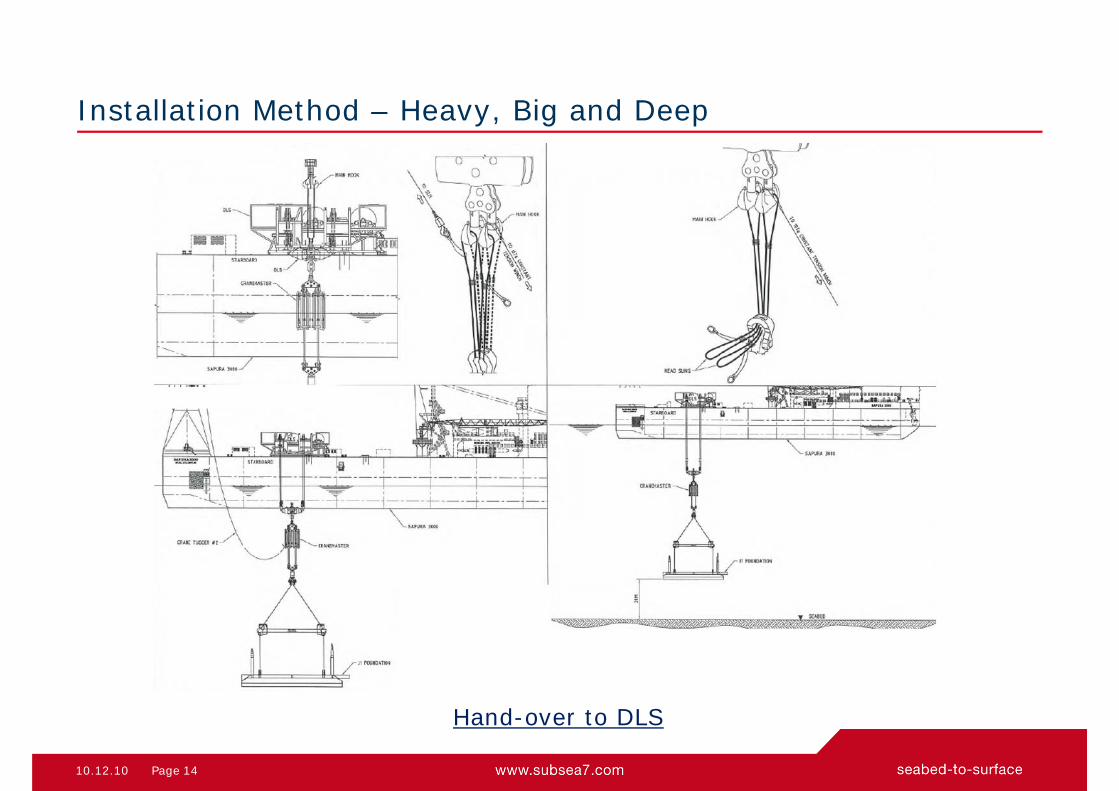
Installation Method – Heavy, Big and Deep
Hand-over to DLS

10.12.10 15Page
Installation Method – Heavy, Big and Deep
Landing
Methods to orientate structure:
• ROV connected to structure• Steered by clump weight
(suspended from vessel crane)

10.12.10 16Page
Video: Jansz Mudmat Installation

10.12.10 17Page
Jansz Mudmat Lift-off
Jansz lifted (938 t) In front: Jansz PTS Module (1113 t)

10.12.10 18Page
Jansz Mudmat Immersion
Cargo Barge removed

19Page 22-Apr-14
Top Related