Languages
Pages
Legal


First Test Measurements of a 64k pixel First Test Measurements of a 64k pixel readout chip working in single photon readout chip working in single photon
counting modecounting mode
X. Llopart
CERN, 1211 Geneva 23, Switzerland
On behalf of the Medipix2 Collaboration*
* See: http://medipix.web.cern.ch/MEDIPIX/

September 2002 Xavier Llopart 2
OutlineOutline
u Introductionu Motivation for the chip designu The Medipix2 pixel cellu The Medipix2 chip architectureu Electrical measurementsu Conclusionsu Future work

September 2002 Xavier Llopart 3
Medipix1 image of a sardineMedipix1 image of a sardine
X-ray tubeMo target 30 µm Mo filter25 kV5 mAs50 cm from sourceRaw data

September 2002 Xavier Llopart 4
MotivationsMotivations
u Medipix I proved potential for photon counting pixel detectors.
u Deep sub-micron CMOS (0.25µm) is available and well characterized.
u 170 µm to 55 µm pixel side and 64x64 to 256x256 pixels per chip. Pixel dimensions competitive with film-screen systems.
u More functionality can be added to a smaller pixel.
September 2002 Xavier Llopart 5
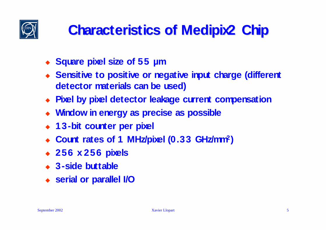
Characteristics of Medipix2 ChipCharacteristics of Medipix2 Chip
u Square pixel size of 55 µm u Sensitive to positive or negative input charge (different
detector materials can be used)u Pixel by pixel detector leakage current compensation u Window in energy as precise as possibleu 13-bit counter per pixel u Count rates of 1 MHz/pixel (0.33 GHz/mm2)u 256 x 256 pixels u 3-side buttableu serial or parallel I/O
September 2002 Xavier Llopart 6
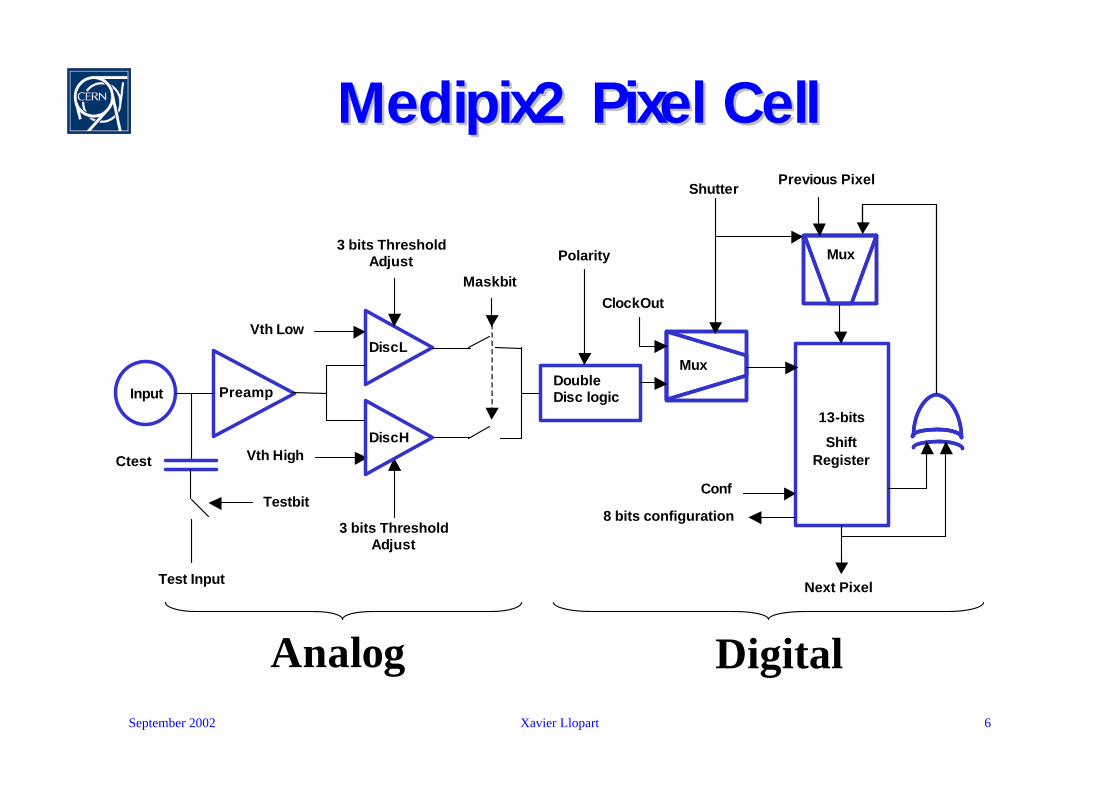
Medipix2 Pixel CellMedipix2 Pixel Cell
Preamp
DiscL
Double Disc logic
Vth Low
Vth High
13-bits
Shift Register
Input
Ctest
Testbit
Test Input
Maskbit
3 bits Threshold Adjust
3 bits Threshold Adjust
Shutter
Mux
Mux
ClockOut
Previous Pixel
Next Pixel
Conf
8 bits configuration
Polarity
Analog Digital
DiscH

September 2002 Xavier Llopart 7
Medipix2 Pixel Cell LayoutMedipix2 Pixel Cell Layout
55 µm
55 µm
55 µm
55 µm

September 2002 Xavier Llopart 8
Medipix2 Chip Architecture (I)Medipix2 Chip Architecture (I)14111 µm
IO
Logic
LVDS
Input
LVDS
Output32-bit CMOS Output
256-bit Fast Shift Register
3328
-bit
Pix
el C
olum
n-0
13 8-bit DACs
14111 µm
3328
-bit
Pix
el C
olum
n-1
3328
-bit
Pix
el C
olum
n-1
1612
0 µ
m
IO
Logic
LVDS
Input
LVDS
Output32-bit CMOS Output
256-bit Fast Shift Register
3328
-bit
Pix
el C
olum
n-0
13 8-bit DACs
14111 µm
3328
-bit
Pix
el C
olum
n-1
3328
-bit
Pix
el C
olum
n-1
1612
0 µ
m
September 2002 Xavier Llopart 9
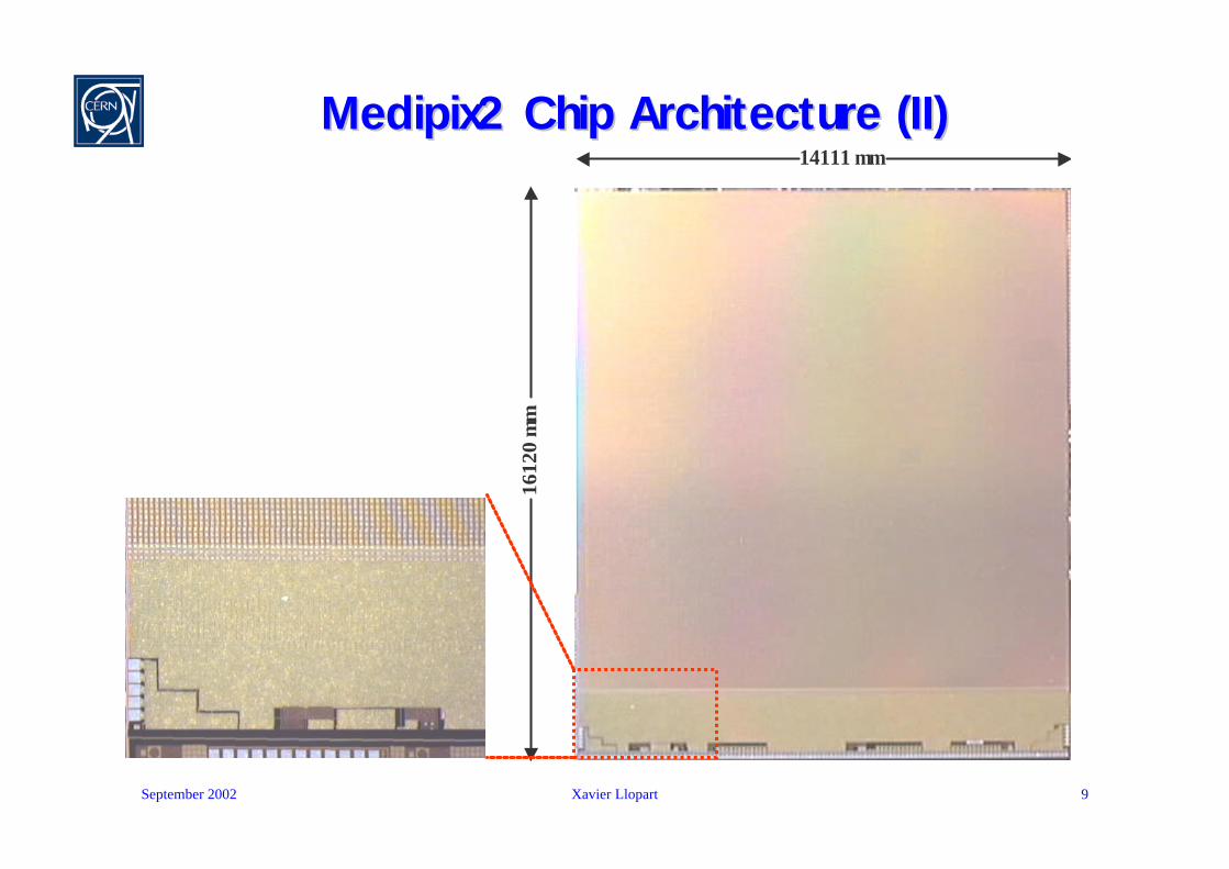
Medipix2 Chip Architecture (II)Medipix2 Chip Architecture (II)14111 µm
14111 µm
1612
0 µ
m

September 2002 Xavier Llopart 10
Measurement SetupMeasurement Setup
September 2002 Xavier Llopart 11
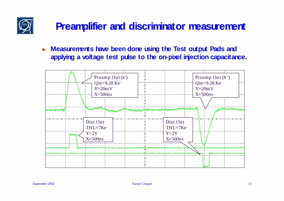
Preamplifier and discriminator measurementPreamplifier and discriminator measurement
u Measurements have been done using the Test output Pads and applying a voltage test pulse to the on-pixel injection capacitance.
Preamp Out (e-)Qin=9.28 Ke-
Y=20mVX=500ns
Preamp Out (h+)Qin=9.28 Ke-
Y=20mVX=500ns
Disc OutTHL=7Ke-
Y=2VX=500ns
Disc OutTHL=7Ke-
Y=2VX=500ns
September 2002 Xavier Llopart 12
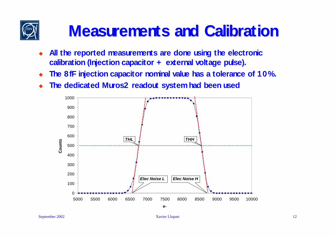
Measurements and CalibrationMeasurements and Calibrationu All the reported measurements are done using the electronic
calibration (Injection capacitor + external voltage pulse). u The 8fF injection capacitor nominal value has a tolerance of 10%.u The dedicated Muros2 readout system had been used
0
100
200
300
400
500
600
700
800
900
1000
5000 5500 6000 6500 7000 7500 8000 8500 9000 9500 10000
e-
Cou
nts THL
Elec Noise L Elec Noise H
THH
September 2002 Xavier Llopart 13
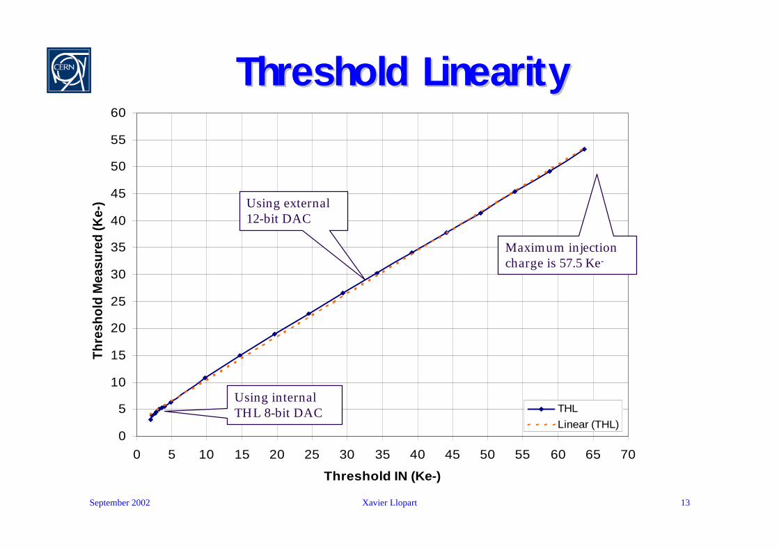
Threshold LinearityThreshold Linearity
0
5
10
15
20
25
30
35
40
45
50
55
60
0 5 10 15 20 25 30 35 40 45 50 55 60 65 70
Threshold IN (Ke-)
Thre
shol
d M
easu
red
(Ke-
)
THLLinear (THL)
Using internal THL 8-bit DAC
Using external 12-bit DAC
Maximum injection charge is 57.5 Ke-
September 2002 Xavier Llopart 14
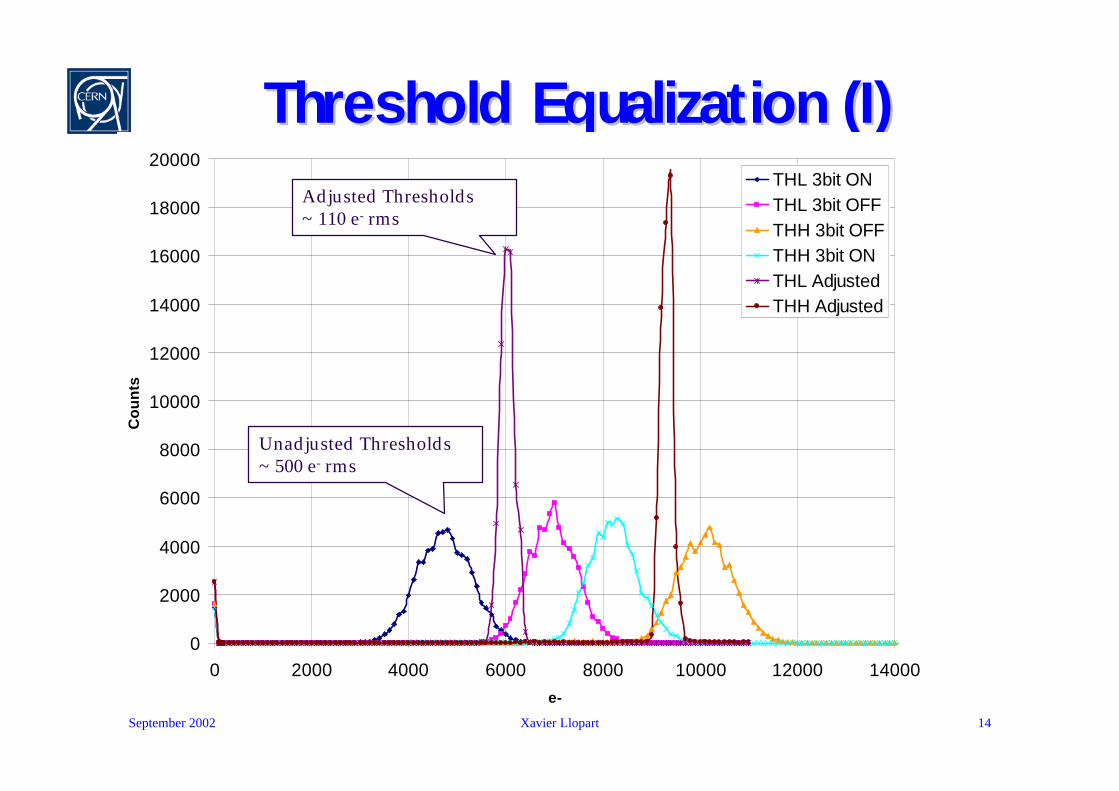
Threshold Equalization (I)Threshold Equalization (I)
0
2000
4000
6000
8000
10000
12000
14000
16000
18000
20000
0 2000 4000 6000 8000 10000 12000 14000e-
Co
un
ts
THL 3bit ONTHL 3bit OFFTHH 3bit OFFTHH 3bit ONTHL AdjustedTHH Adjusted
Unadjusted Thresholds ~ 500 e- rms
Adjusted Thresholds~ 110 e- rms
September 2002 Xavier Llopart 15
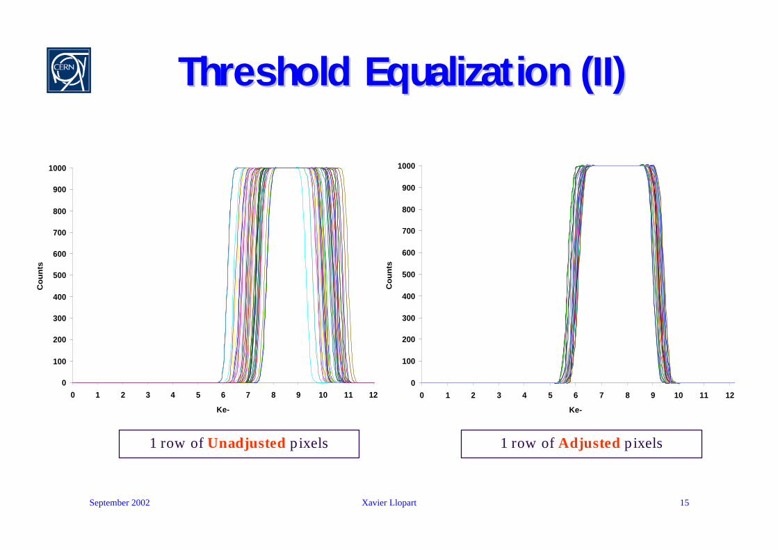
Threshold Equalization (II)Threshold Equalization (II)
1 row of Unadjusted pixels 1 row of Adjusted pixels
0
100
200
300
400
500
600
700
800
900
1000
0 1 2 3 4 5 6 7 8 9 10 11 12
Ke-
Co
un
ts
0
100
200
300
400
500
600
700
800
900
1000
0 1 2 3 4 5 6 7 8 9 10 11 12
Ke-
Co
un
ts

September 2002 Xavier Llopart 16
0
100000
200000
300000
400000
500000
600000
700000
800000
900000
1000000
0 2000 4000 6000 8000 10000 12000 14000
e-
Sum
of c
ount
s 30
x30
UnadjustedAdjusted
Threshold Equalization (III)Threshold Equalization (III)•THL=120•THL=100•Matrix unmasked•30x30 pixels active

September 2002 Xavier Llopart 17
0
100000
200000
300000
400000
500000
600000
700000
800000
900000
1000000
0 2000 4000 6000 8000 10000 12000 14000
e-
Sum
of c
ount
s 30
x30
UnadjustedAdjusted
Threshold Equalization (IV)Threshold Equalization (IV)•THL=120•THL=110•Matrix unmasked•30x30 pixels active
September 2002 Xavier Llopart 18
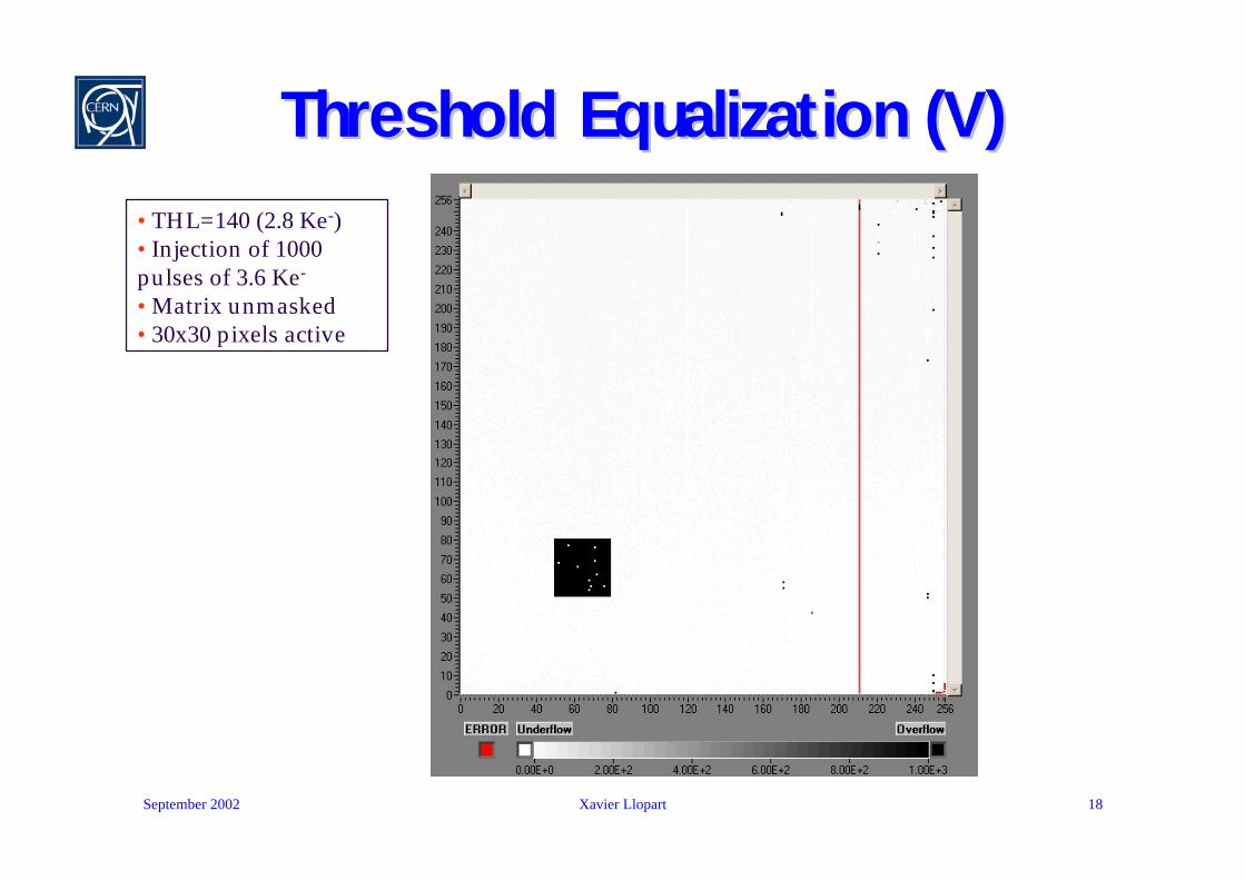
Threshold Equalization (V)Threshold Equalization (V)•THL=140 (2.8 Ke-)•Injection of 1000 pulses of 3.6 Ke-
•Matrix unmasked•30x30 pixels active

September 2002 Xavier Llopart 19
Summary of the Electrical MeasurementsSummary of the Electrical Measurements
σnTHL~ 110 e- σnTHH~ 110 e-Adjusted Threshold dispersion
~8 µW/channel for a 2.2 V supplyAnalog power dissipation
σnTHL~ 500 e- σnTHH~ 500 e-Threshold dispersion
σnL~ 105 e- σnH~ 105 e-Electronic Noise
<1µs for Qin <50 ke-Return to baseline
<200 nsPeaking time
<3% to 80 ke-<3% to 100 ke-Non linearity
13.25 mV/ke-12.5 mV/ke-Gain
Holes Collection
Electron Collection
September 2002 Xavier Llopart 20
Periphery MeasurementsPeriphery Measurements
u The 13 DACs perform as simulationsu Fast shift register works at > 100 Mhz*u Peripheral logic works to > 100 Mhz*u Serial/parallel I/O worku LVDS drivers and receivers work to > 100 MHz*
* IC-Tester maximum clock frequency
September 2002 Xavier Llopart 21
Radiation Tolerance MeasurementsRadiation Tolerance Measurements
u 10 keV X-ray source
u Chip under bias conditions
u Applied dose rates:u 3.9 krad/min up to 150 krad
u 8.04 krad/min from 150 krad to 500 krad
u Analog power supply current increase from 200mA to 260 mA
u Digital power supply current increase sharply @ 200 krad reaching 1100 mA @ 500 krad
u After 1 week of annealing at 100°C the power supplies current recovered to pre-irradiation values
u Chip showed normal behavior untill 200 krad and still functioning after annealing at 500 krad
September 2002 Xavier Llopart 22
ConclusionsConclusions
u A prototype chip consisting of 256x256 pixels has been produced with a square pixel size of 55 µm. Each pixel has around 500 transistors.
u Using the dedicated Medipix2 readout system (Muros2 and Medisoft4) complete electronic measurements and threshold calibration have been done.
u Adjusted threshold variation ~110 e- rms for both levels of discrimination.
u Electronic Noise ~105 e- rms.
u Difficulties to lower the threshold under 2.5 Ke- with the present setup.
u The chip is radiation tolerant until at least 200 Krad.
September 2002 Xavier Llopart 23
OnOn--going workgoing worku A new chipboard card is ready to be tested with
improved decoupling and power distribution.
u Probe tested wafers have been sent for bump bonding to silicon detectors.
u This should allow an absolute calibration with radioactive sources.
u Other materials will be tried later ( CdTe, GaAs, etc…)

September 2002 Xavier Llopart 24
Future ProspectsFuture Prospects
u With pixel shrinking charge sharing starts to dominate the detector behavior.
u Hexagonal pixels (on the detector side) become attractive.
u New front-end electronics architectures are needed.
u Some ideas are presented in a recently accepted paper for publication in the NSS/MIC IEEE journal.
u A whole spectrum of new possibilities opens with e.g. time-resolved measurements, very high dynamic range applications, colour X-ray imaging…
Top Related