First Test Measurements of a 64k pixel readout chip ... · First Test Measurements of a 64k pixel...
24
First Test Measurements of a 64k pixel First Test Measurements of a 64k pixel readout chip working in single photon readout chip working in single photon counting mode counting mode X. Llopart CERN, 1211 Geneva 23, Switzerland On behalf of the Medipix2 Collaboration* * See: http://medipix.web.cern.ch/MEDIPIX/
-
Upload
nguyenminh -
Category
Documents
-
view
226 -
download
0
Transcript of First Test Measurements of a 64k pixel readout chip ... · First Test Measurements of a 64k pixel...

First Test Measurements of a 64k pixel First Test Measurements of a 64k pixel readout chip working in single photon readout chip working in single photon
counting modecounting mode
X. Llopart
CERN, 1211 Geneva 23, Switzerland
On behalf of the Medipix2 Collaboration*
* See: http://medipix.web.cern.ch/MEDIPIX/

September 2002 Xavier Llopart 2
OutlineOutline
u Introductionu Motivation for the chip designu The Medipix2 pixel cellu The Medipix2 chip architectureu Electrical measurementsu Conclusionsu Future work

September 2002 Xavier Llopart 3
Medipix1 image of a sardineMedipix1 image of a sardine
X-ray tubeMo target 30 µm Mo filter25 kV5 mAs50 cm from sourceRaw data

September 2002 Xavier Llopart 4
MotivationsMotivations
u Medipix I proved potential for photon counting pixel detectors.
u Deep sub-micron CMOS (0.25µm) is available and well characterized.
u 170 µm to 55 µm pixel side and 64x64 to 256x256 pixels per chip. Pixel dimensions competitive with film-screen systems.
u More functionality can be added to a smaller pixel.
September 2002 Xavier Llopart 5
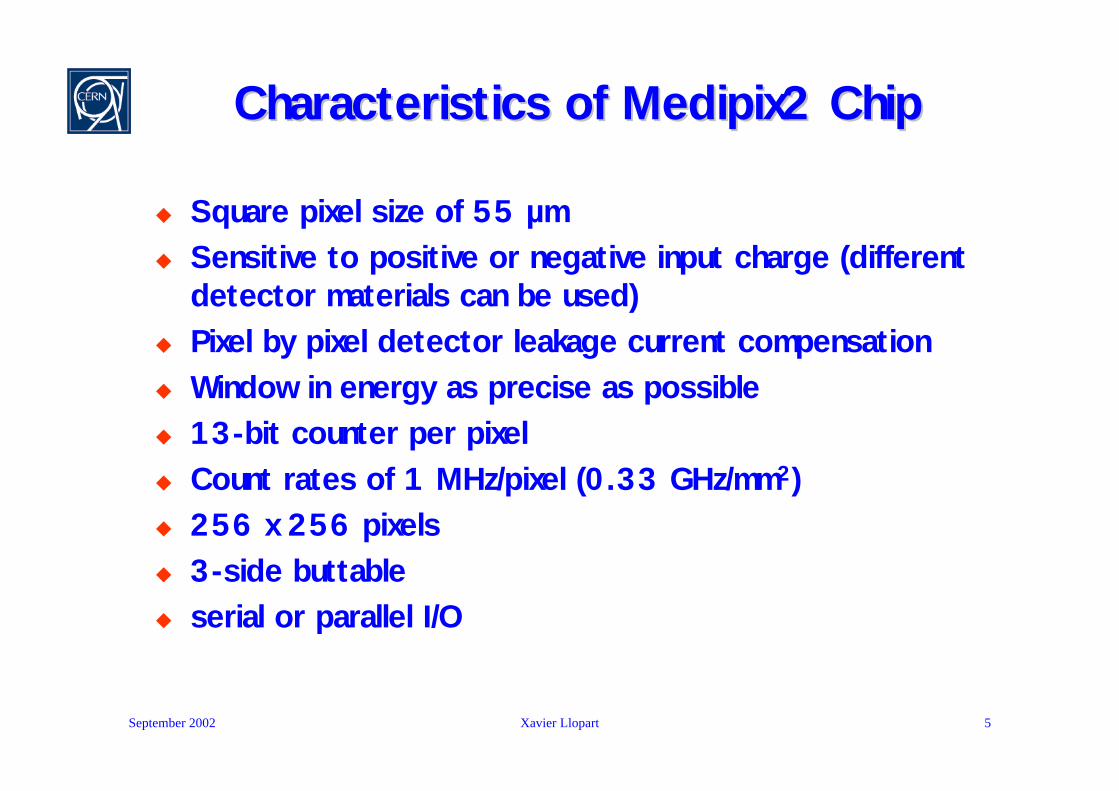
Characteristics of Medipix2 ChipCharacteristics of Medipix2 Chip
u Square pixel size of 55 µm u Sensitive to positive or negative input charge (different
detector materials can be used)u Pixel by pixel detector leakage current compensation u Window in energy as precise as possibleu 13-bit counter per pixel u Count rates of 1 MHz/pixel (0.33 GHz/mm2)u 256 x 256 pixels u 3-side buttableu serial or parallel I/O
September 2002 Xavier Llopart 6
Medipix2 Pixel CellMedipix2 Pixel Cell
Preamp
DiscL
Double Disc logic
Vth Low
Vth High
13-bits
Shift Register
Input
Ctest
Testbit
Test Input
Maskbit
3 bits Threshold Adjust
3 bits Threshold Adjust
Shutter
Mux
Mux
ClockOut
Previous Pixel
Next Pixel
Conf
8 bits configuration
Polarity
Analog Digital
DiscH

September 2002 Xavier Llopart 7
Medipix2 Pixel Cell LayoutMedipix2 Pixel Cell Layout
55 µm
55 µm
55 µm
55 µm

September 2002 Xavier Llopart 8
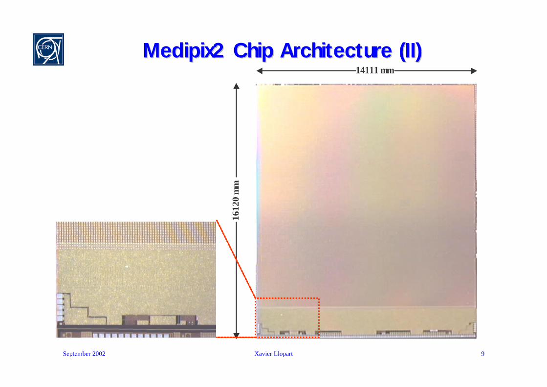
Medipix2 Chip Architecture (I)Medipix2 Chip Architecture (I)14111 µm
IO
Logic
LVDS
Input
LVDS
Output32-bit CMOS Output
256-bit Fast Shift Register
3328
-bit
Pix
el C
olum
n-0
13 8-bit DACs
14111 µm
3328
-bit
Pix
el C
olum
n-1
3328
-bit
Pix
el C
olum
n-1
1612
0 µ
m
IO
Logic
LVDS
Input
LVDS
Output32-bit CMOS Output
256-bit Fast Shift Register
3328
-bit
Pix
el C
olum
n-0
13 8-bit DACs
14111 µm
3328
-bit
Pix
el C
olum
n-1
3328
-bit
Pix
el C
olum
n-1
1612
0 µ
m
September 2002 Xavier Llopart 9
Medipix2 Chip Architecture (II)Medipix2 Chip Architecture (II)14111 µm
14111 µm
1612
0 µ
m

September 2002 Xavier Llopart 10
Measurement SetupMeasurement Setup
September 2002 Xavier Llopart 11
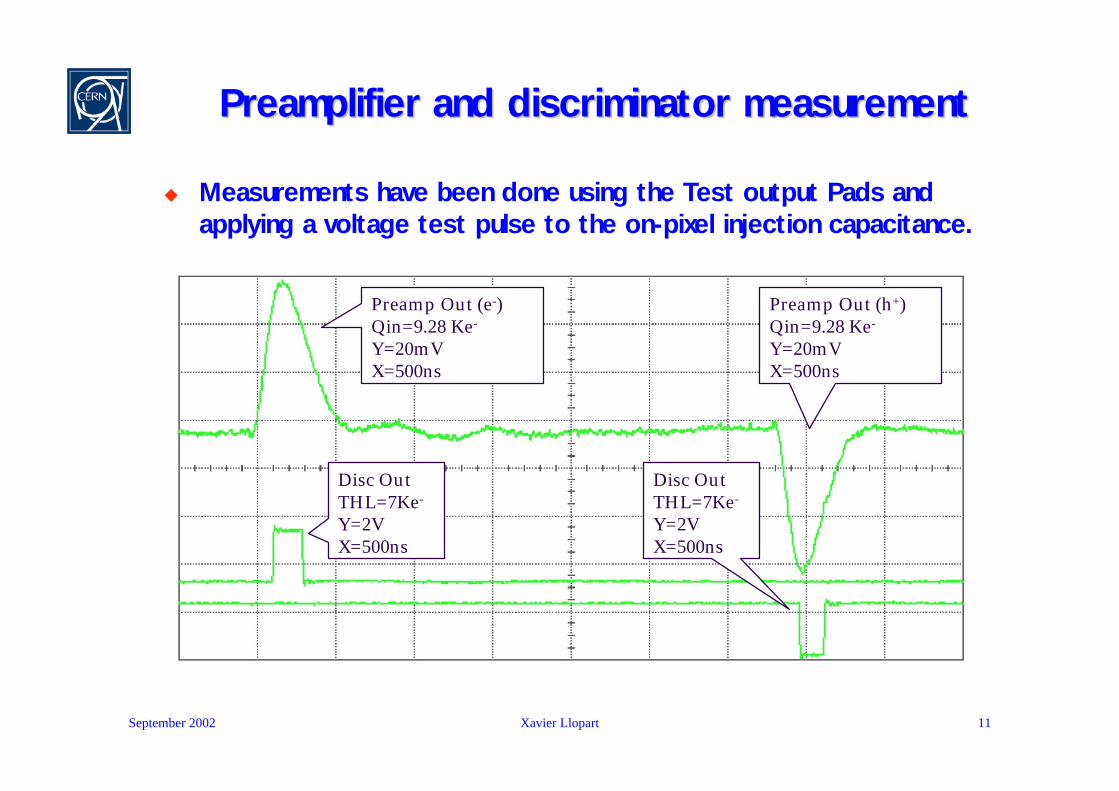
Preamplifier and discriminator measurementPreamplifier and discriminator measurement
u Measurements have been done using the Test output Pads and applying a voltage test pulse to the on-pixel injection capacitance.
Preamp Out (e-)Qin=9.28 Ke-
Y=20mVX=500ns
Preamp Out (h+)Qin=9.28 Ke-
Y=20mVX=500ns
Disc OutTHL=7Ke-
Y=2VX=500ns
Disc OutTHL=7Ke-
Y=2VX=500ns
September 2002 Xavier Llopart 12
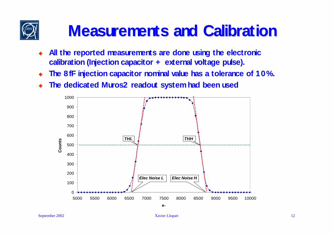
Measurements and CalibrationMeasurements and Calibrationu All the reported measurements are done using the electronic
calibration (Injection capacitor + external voltage pulse). u The 8fF injection capacitor nominal value has a tolerance of 10%.u The dedicated Muros2 readout system had been used
0
100
200
300
400
500
600
700
800
900
1000
5000 5500 6000 6500 7000 7500 8000 8500 9000 9500 10000
e-
Cou
nts THL
Elec Noise L Elec Noise H
THH
September 2002 Xavier Llopart 13
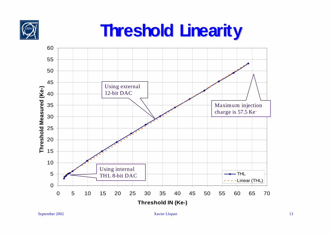
Threshold LinearityThreshold Linearity
0
5
10
15
20
25
30
35
40
45
50
55
60
0 5 10 15 20 25 30 35 40 45 50 55 60 65 70
Threshold IN (Ke-)
Thre
shol
d M
easu
red
(Ke-
)
THLLinear (THL)
Using internal THL 8-bit DAC
Using external 12-bit DAC
Maximum injection charge is 57.5 Ke-
September 2002 Xavier Llopart 14
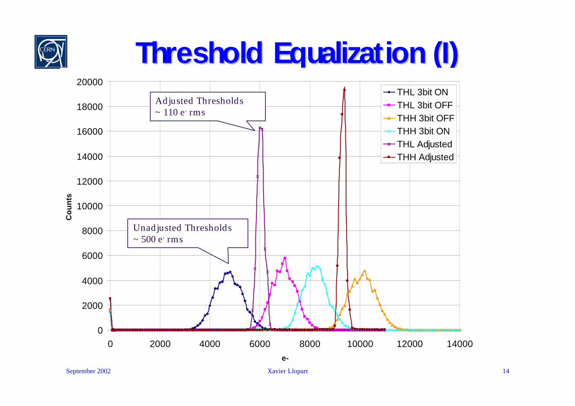
Threshold Equalization (I)Threshold Equalization (I)
0
2000
4000
6000
8000
10000
12000
14000
16000
18000
20000
0 2000 4000 6000 8000 10000 12000 14000e-
Co
un
ts
THL 3bit ONTHL 3bit OFFTHH 3bit OFFTHH 3bit ONTHL AdjustedTHH Adjusted
Unadjusted Thresholds ~ 500 e- rms
Adjusted Thresholds~ 110 e- rms
September 2002 Xavier Llopart 15
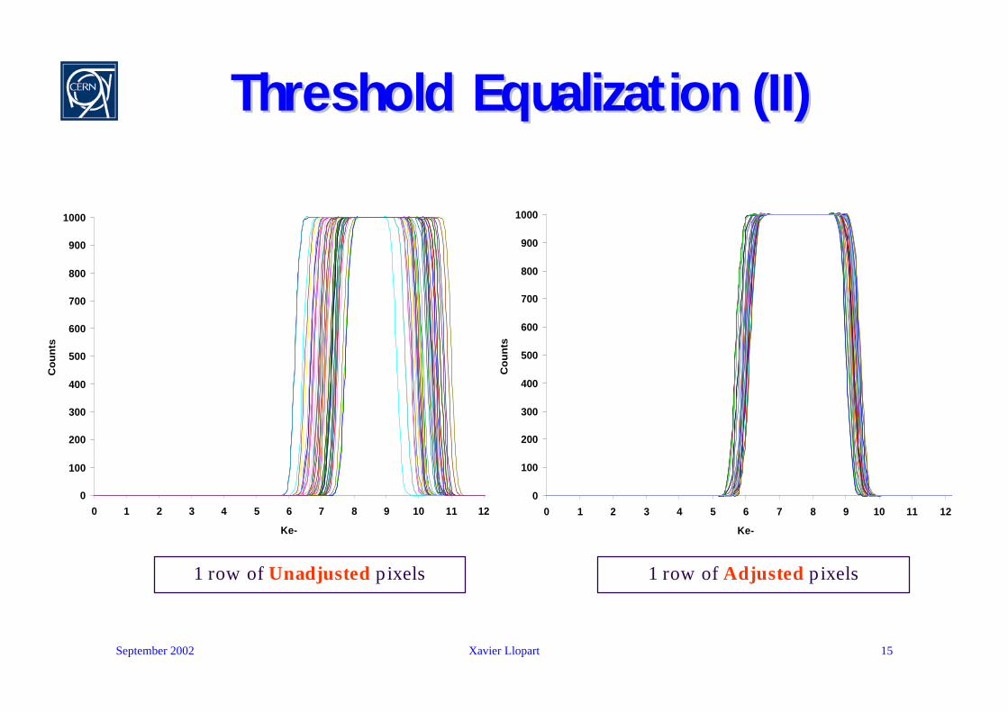
Threshold Equalization (II)Threshold Equalization (II)
1 row of Unadjusted pixels 1 row of Adjusted pixels
0
100
200
300
400
500
600
700
800
900
1000
0 1 2 3 4 5 6 7 8 9 10 11 12
Ke-
Co
un
ts
0
100
200
300
400
500
600
700
800
900
1000
0 1 2 3 4 5 6 7 8 9 10 11 12
Ke-
Co
un
ts

September 2002 Xavier Llopart 16
0
100000
200000
300000
400000
500000
600000
700000
800000
900000
1000000
0 2000 4000 6000 8000 10000 12000 14000
e-
Sum
of c
ount
s 30
x30
UnadjustedAdjusted
Threshold Equalization (III)Threshold Equalization (III)•THL=120•THL=100•Matrix unmasked•30x30 pixels active

September 2002 Xavier Llopart 17
0
100000
200000
300000
400000
500000
600000
700000
800000
900000
1000000
0 2000 4000 6000 8000 10000 12000 14000
e-
Sum
of c
ount
s 30
x30
UnadjustedAdjusted
Threshold Equalization (IV)Threshold Equalization (IV)•THL=120•THL=110•Matrix unmasked•30x30 pixels active
September 2002 Xavier Llopart 18
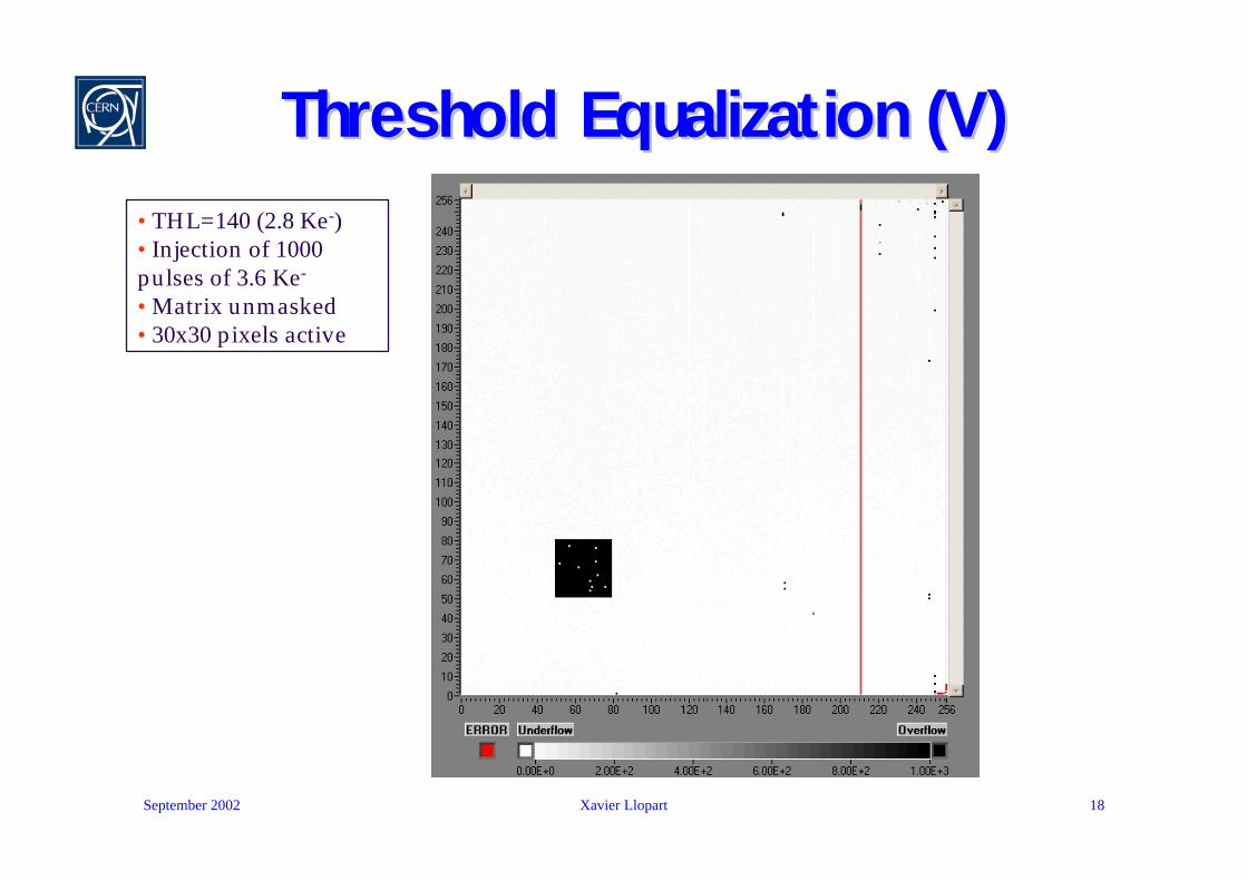
Threshold Equalization (V)Threshold Equalization (V)•THL=140 (2.8 Ke-)•Injection of 1000 pulses of 3.6 Ke-
•Matrix unmasked•30x30 pixels active

September 2002 Xavier Llopart 19
Summary of the Electrical MeasurementsSummary of the Electrical Measurements
σnTHL~ 110 e- σnTHH~ 110 e-Adjusted Threshold dispersion
~8 µW/channel for a 2.2 V supplyAnalog power dissipation
σnTHL~ 500 e- σnTHH~ 500 e-Threshold dispersion
σnL~ 105 e- σnH~ 105 e-Electronic Noise
<1µs for Qin <50 ke-Return to baseline
<200 nsPeaking time
<3% to 80 ke-<3% to 100 ke-Non linearity
13.25 mV/ke-12.5 mV/ke-Gain
Holes Collection
Electron Collection
September 2002 Xavier Llopart 20
Periphery MeasurementsPeriphery Measurements
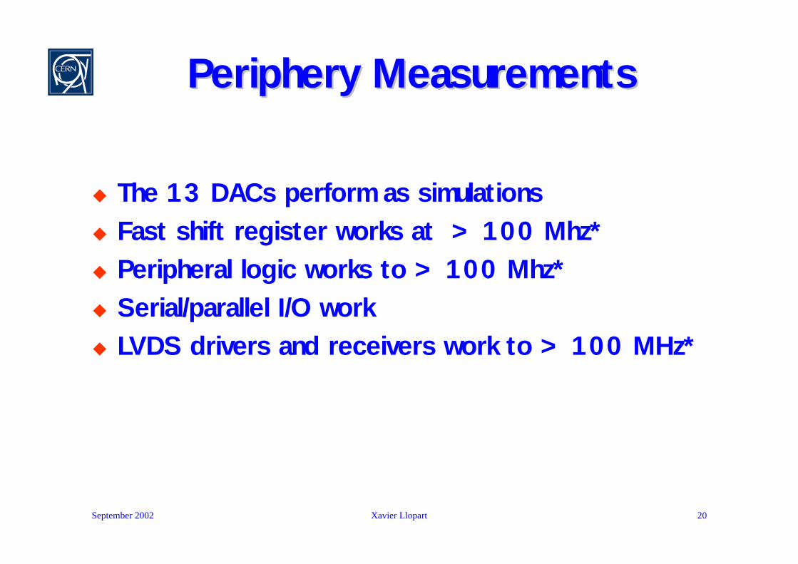
u The 13 DACs perform as simulationsu Fast shift register works at > 100 Mhz*u Peripheral logic works to > 100 Mhz*u Serial/parallel I/O worku LVDS drivers and receivers work to > 100 MHz*
* IC-Tester maximum clock frequency
September 2002 Xavier Llopart 21
Radiation Tolerance MeasurementsRadiation Tolerance Measurements
u 10 keV X-ray source
u Chip under bias conditions
u Applied dose rates:u 3.9 krad/min up to 150 krad
u 8.04 krad/min from 150 krad to 500 krad
u Analog power supply current increase from 200mA to 260 mA
u Digital power supply current increase sharply @ 200 krad reaching 1100 mA @ 500 krad
u After 1 week of annealing at 100°C the power supplies current recovered to pre-irradiation values
u Chip showed normal behavior untill 200 krad and still functioning after annealing at 500 krad
September 2002 Xavier Llopart 22
ConclusionsConclusions
u A prototype chip consisting of 256x256 pixels has been produced with a square pixel size of 55 µm. Each pixel has around 500 transistors.
u Using the dedicated Medipix2 readout system (Muros2 and Medisoft4) complete electronic measurements and threshold calibration have been done.
u Adjusted threshold variation ~110 e- rms for both levels of discrimination.
u Electronic Noise ~105 e- rms.
u Difficulties to lower the threshold under 2.5 Ke- with the present setup.
u The chip is radiation tolerant until at least 200 Krad.
September 2002 Xavier Llopart 23
OnOn--going workgoing worku A new chipboard card is ready to be tested with
improved decoupling and power distribution.
u Probe tested wafers have been sent for bump bonding to silicon detectors.
u This should allow an absolute calibration with radioactive sources.
u Other materials will be tried later ( CdTe, GaAs, etc…)

September 2002 Xavier Llopart 24
Future ProspectsFuture Prospects
u With pixel shrinking charge sharing starts to dominate the detector behavior.
u Hexagonal pixels (on the detector side) become attractive.
u New front-end electronics architectures are needed.
u Some ideas are presented in a recently accepted paper for publication in the NSS/MIC IEEE journal.
u A whole spectrum of new possibilities opens with e.g. time-resolved measurements, very high dynamic range applications, colour X-ray imaging…