


Languages
Pages
Legal


Design of Structural Steel Joints
Dr. Klaus WeynandFeldmann + Weynand GmbH, Aachen, Germany
Prof. Jean-Pierre JaspartUniversity of Liège, Belgium

Design of Structural Steel Joints
• Introduction
• Integration of joints into structural design process
• Moment resistant joints
• Simple joints
• Design tools

Design of Structural Steel Joints
• Introduction• Integration of joints into
structural design process
• Moment resistant joints
• Simple joints
• Design tools

Eurocodes - Design of steel buildings with worked examples Brussels, 16 - 17 October 2014
EN 1993 Part 1.8
Chapter 1 – Introduction
Chapter 2 – Basis of design
Chapter 3 – Connections made with bolts, rivets or pins
Chapter 4 – Welded connections
Chapter 5 – Analysis, classification and modelling
Chapter 6 – Structural joints connecting H or I sections
Chapter 7 – Hollow section joints

Eurocodes - Design of steel buildings with worked examples Brussels, 16 - 17 October 2014
Design of simple joints
ECCS Publication No 126 (EN)
• Background information
• Design guidelines
Eurocodes - Design of steel buildings with worked examples Brussels, 16 - 17 October 2014
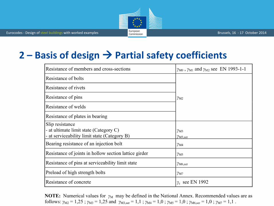
2 – Basis of design Partial safety coefficients

Eurocodes - Design of steel buildings with worked examples Brussels, 16 - 17 October 2014
3 – Connections made mechanical fasteners

Eurocodes - Design of steel buildings with worked examples Brussels, 16 - 17 October 2014
4 – Welded connections

Design of Structural Steel Joints
• Introduction
• Integration of joints into structural design process
• Moment resistant joints
• Simple joints
• Design tools

Eurocodes - Design of steel buildings with worked examples Brussels, 16 - 17 October 2014
Actual joint response

Eurocodes - Design of steel buildings with worked examples Brussels, 16 - 17 October 2014
Actual joint response
M
M Rd
S j,inicd

Eurocodes - Design of steel buildings with worked examples Brussels, 16 - 17 October 2014
Influence on the structural response
• Displacements
• Internal forces
• Failure mode and failure load

Eurocodes - Design of steel buildings with worked examples Brussels, 16 - 17 October 2014
M
M
?
?
?
M
Characterization
Modelling
Classification
Idealization
Four successive steps for structural integration

Eurocodes - Design of steel buildings with worked examples Brussels, 16 - 17 October 2014
Characterization
Search for a unified approach whatever the material
M
?
?
?

Eurocodes - Design of steel buildings with worked examples Brussels, 16 - 17 October 2014
Various configurations (1)Continuity
Beam-to-beam
Column bases
Eurocodes - Design of steel buildings with worked examples Brussels, 16 - 17 October 2014
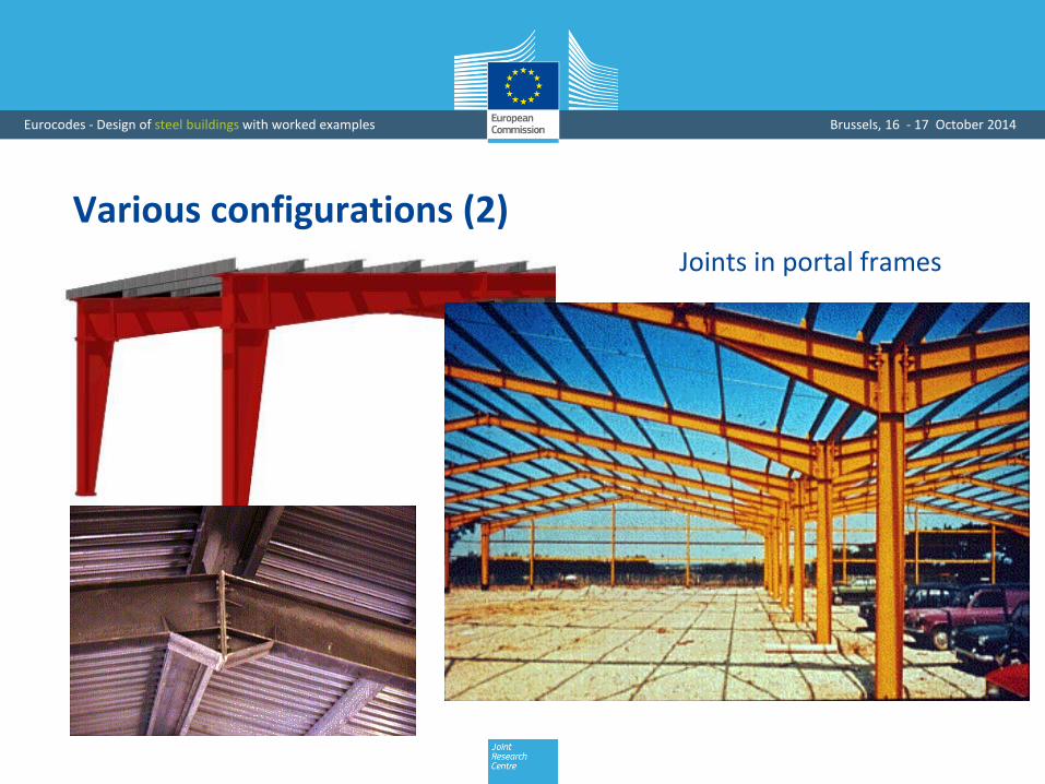
Various configurations (2)Joints in portal frames

Eurocodes - Design of steel buildings with worked examples Brussels, 16 - 17 October 2014
Various configurations (3)
Connections and joints incomposite construction

Eurocodes - Design of steel buildings with worked examples Brussels, 16 - 17 October 2014
Various cross-section shapes (1)
Hot-rolled and
cold-formed

Eurocodes - Design of steel buildings with worked examples Brussels, 16 - 17 October 2014
Various cross-section shapes (2)
Built-up profiles

Eurocodes - Design of steel buildings with worked examples Brussels, 16 - 17 October 2014
Various connection elements
Splices
Cleats
End plates

Eurocodes - Design of steel buildings with worked examples Brussels, 16 - 17 October 2014
Economy
Reduced fabrication, transportation and erection costs

Eurocodes - Design of steel buildings with worked examples Brussels, 16 - 17 October 2014
Specific design criteria
Robustness
Joints as key elements

Eurocodes - Design of steel buildings with worked examples Brussels, 16 - 17 October 2014
Characterization (1)
Search for a unified approach
M
?
?
?

Eurocodes - Design of steel buildings with worked examples Brussels, 16 - 17 October 2014
Characterization (2)
Eurocode 3 – Part 1-8
• Beam-to-beam joints, splices, beam-to-column joints and column
bases:
welded connections
bolted connections (anchors for column bases)
Background: COMPONENT METHOD
Eurocodes - Design of steel buildings with worked examples Brussels, 16 - 17 October 2014
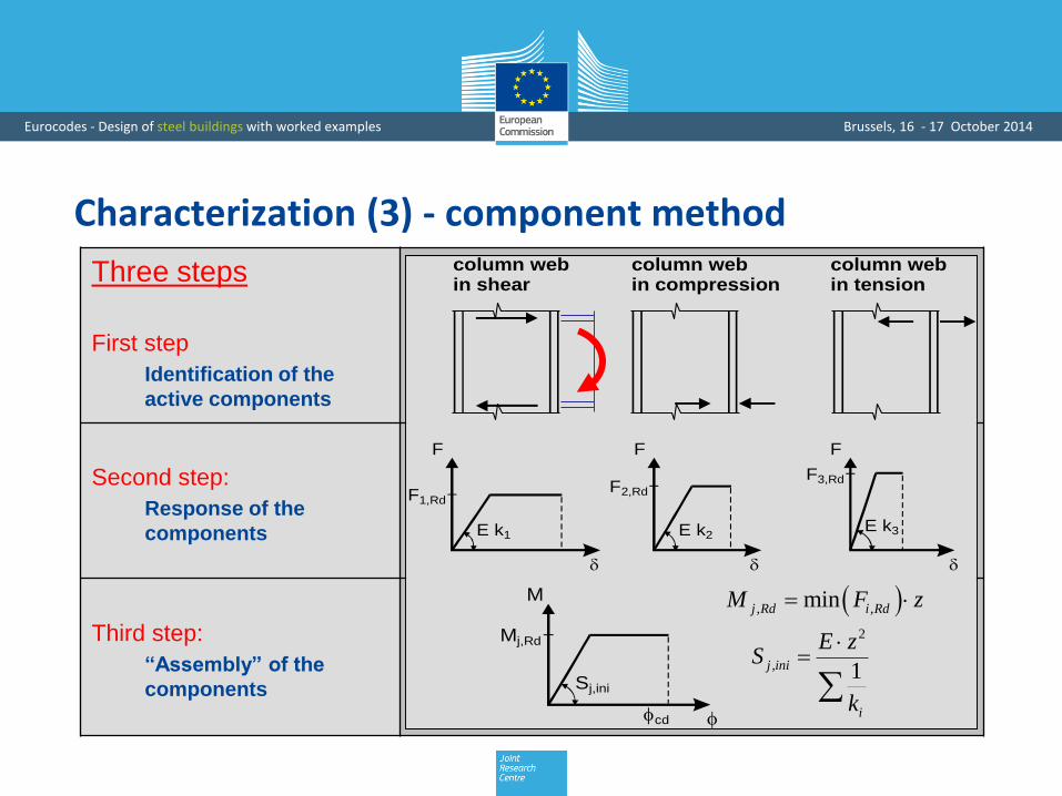
Three steps
First step
Identification of the
active components
Second step:
Response of the
components
Third step:
“Assembly” of the
components
F F F
E k1 E k2E k3
F1,RdF2,Rd
F3,Rd
column webin shear
column webin tension
column webin compression
M
Sj,ini
Mj,Rd
cd
, ,minj Rd i RdM F z
2
, 1j ini
i
E zS
k
Characterization (3) - component method

Eurocodes - Design of steel buildings with worked examples Brussels, 16 - 17 October 2014
Characterization (4) - component method
EC3 Part 1-8 provides therefore:
• a library of components
• rules for the evaluation of the properties of the components
(stiffness, resistance, deformation capacity)
• rules for the evaluation of the possible component interactions
• « assembly » rules for components
Applicable for simple joint and moment resistant joint

Eurocodes - Design of steel buildings with worked examples Brussels, 16 - 17 October 2014
Characterization (4) – Hollow section jointsDifferent approach for lattice girder joints
For many types of joint configurations:
• Joints considered as a whole
• Check of relevant failure modes
• Scope of application to be checked

Eurocodes - Design of steel buildings with worked examples Brussels, 16 - 17 October 2014
M
M
?
?
?
M
Characterization
Modelling
Classification
Idealization
Four successive steps for structural integration

Eurocodes - Design of steel buildings with worked examples Brussels, 16 - 17 October 2014
Classification (1)
Stiffness
Sj,ini
Pinned
Semi-rigid
RigidM j
Boundaries for stiffness
Joint initial stiffness
Semi-rigid
Rigid
Pinned
Classification boundariesInitial joint stiffness

Eurocodes - Design of steel buildings with worked examples Brussels, 16 - 17 October 2014
Classification (2)
Resistance
Mj,Rd
Partial-strength
Full-strength
Pinned
Mj
Boundaries for strength
Joint strength
Full resistance
Partial resistance
Pinned
Classification boundariesJoint resistance

Eurocodes - Design of steel buildings with worked examples Brussels, 16 - 17 October 2014
Classification (3)
Ductility
• Brittle
• “Semi-ductile”
• Ductile
Mj

Eurocodes - Design of steel buildings with worked examples Brussels, 16 - 17 October 2014
M
M
?
?
?
M
Characterization
Modelling
Classification
Idealization
Four successive steps for structural integration

Eurocodes - Design of steel buildings with worked examples Brussels, 16 - 17 October 2014
Modelling
JOINT
MODELLING
BEAM-TO-COLUMN JOINTS
MAJOR AXIS BENDING
BEAM
SPLICES
COLUMN
BASES
SIMPLE
SEMI-
CONTINUOUS
CONTINUOUS

Eurocodes - Design of steel buildings with worked examples Brussels, 16 - 17 October 2014
M
M
?
?
?
M
Characterization
Modelling
Classification
Idealization
Four successive steps for structural integration

Design of Structural Steel Joints
• Introduction
• Integration of joints into structural design process
• Moment resistant joints• Simple joints
• Design tools

Eurocodes - Design of steel buildings with worked examples Brussels, 16 - 17 October 2014
ExampleSingle sided beam-to-column joint configuration, bolted end-plate connection
+ +
+ +
M
V
15
3
IPE220
HEB140
120
60 10
8030 30
240
4 M16 8.8
140
u=10p=60
5
w=
To be evaluated:
Design moment resistance , initial stiffness
0
1
1,01,0
M
M
Material: S 235
Eurocodes - Design of steel buildings with worked examples Brussels, 16 - 17 October 2014
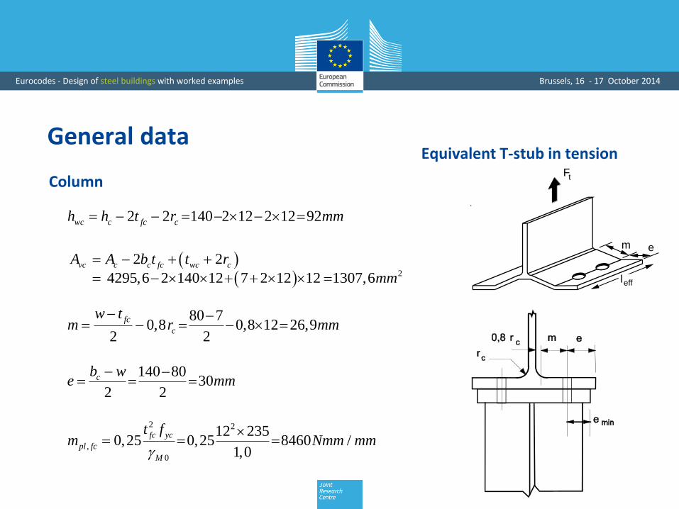
General data
2 2 140 2 12 2 12 92wc c fc ch h t r mm
2
2 2
4295,6 2 140 12 7 2 12 12 1307,6vc c c fc wc cA A b t t r
mm
80 70,8 0,8 12 26,9
2 2
fc
c
w tm r mm
140 8030
2 2
cb we mm
2 2
,
0
12 2350,25 0,25 8460 /
1,0
fc yc
pl fc
M
t fm Nmm mm
Column
Equivalent T-stub in tension
F /4t
Ft
F /4t
F /4t
F /4t
m e
leff

Eurocodes - Design of steel buildings with worked examples Brussels, 16 - 17 October 2014
General data
+ +
+ +
15
3
IPE220120
60 10
8030 30
240
4 M16 8.8
140
u=10p=60
5
w=
z
9,2220 10 60 165,4
2 2
fb
b
tz h u p mm
6,
,
0
285.406 235 10 (classe 1 section) 67,07
1,0
pl yb yb
c Rd
M
W fM kNm
Lever arm
Beam
Eurocodes - Design of steel buildings with worked examples Brussels, 16 - 17 October 2014
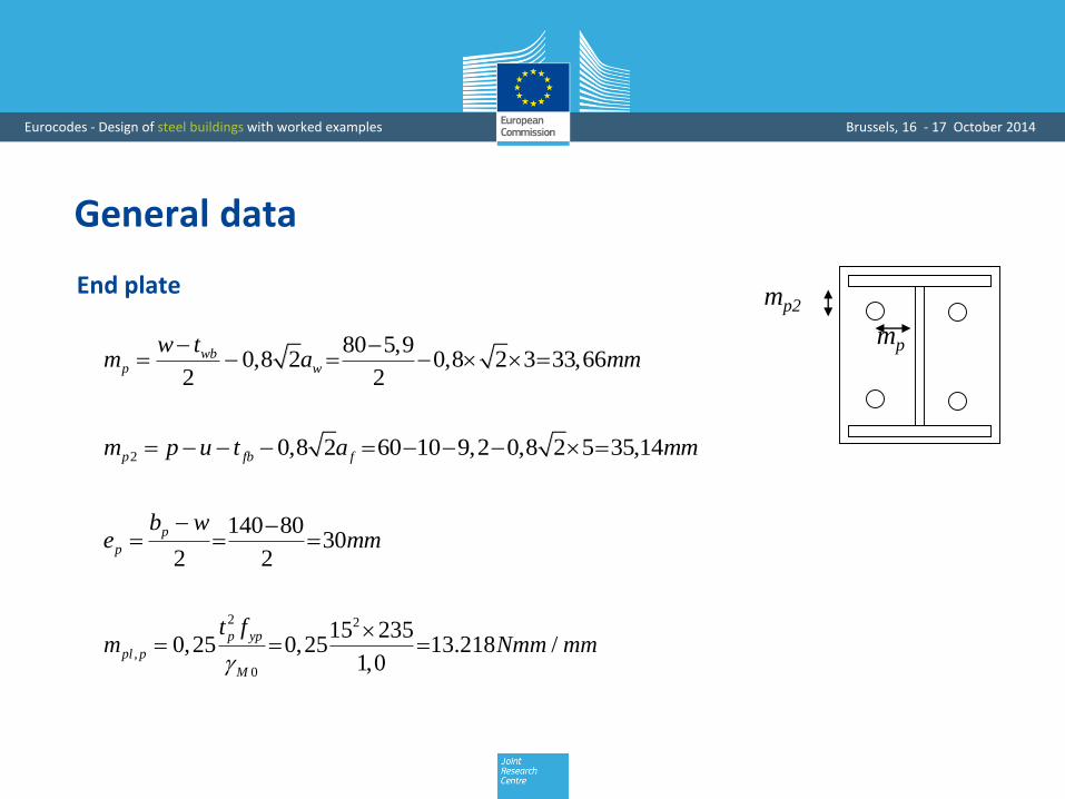
General data
2 2
,
0
15 2350,25 0,25 13.218 /
1,0
p yp
pl p
M
t fm Nmm mm
mp
mp2
80 5,90,8 2 0,8 2 3 33,66
2 2
wbp w
w tm a mm
2 0,8 2 60 10 9,2 0,8 2 5 35,14p fb fm p u t a mm
140 8030
2 2
p
p
b we mm
End plate
Eurocodes - Design of steel buildings with worked examples Brussels, 16 - 17 October 2014
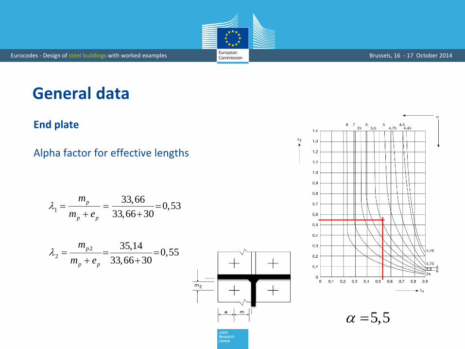
General data
5,5
1
33,660,53
33,66 30
p
p p
m
m e
2
2
35,140,55
33,66 30
p
p p
m
m e
Alpha factor for effective lengths
End plate

Eurocodes - Design of steel buildings with worked examples Brussels, 16 - 17 October 2014
General data
3
,
0,9 0,9 800 157 1090,43
1,25
ub st Rd
Mb
f AF kN
3
,
0,6 0,6 800 157 10 (shear plane in thread) 60,3
1.25
ub sv Rd
Mb
f AF kN
1
0,5 12 15 10 14,8 2 4 47,42
b fc p bolt nutL t t h h mm
Bolts

Eurocodes - Design of steel buildings with worked examples Brussels, 16 - 17 October 2014
Component No 1 – Column web in shear
Vwp
Vwp
F
M
z
F
3,
,
0
0,9 0,9 1307,6 235 10159,7
3 3 1,0
vc y cw
wc Rd
M
A fV kN
Assumption : 1
,
,1
159,7159,7
1
wc Rd
Rd
VF kN
1
0,38 0,38 1307,63,004
1 165,4
vcAk mm
h
Resistance
Stiffness coefficient
Transformation parameter

Eurocodes - Design of steel buildings with worked examples Brussels, 16 - 17 October 2014
Component No 2 – Column web in compression
, , min 2 2 2 5 ; 2 5
min 9,2 2 5 2 2 15 5 12 12 ; 9,2 5 2 15 10 5 12 12 161,27
eff c wc fb f p fc fb f p fcb t a t t s t a t u t s
mm
, ,Assumption : min 1,0; 1,7 / 1,0wc com Ed y wck f
, , ,
2
161,27 92 2350,932 0,932 0,543 0,673 1,0
210000 7 7
eff c wc c y wc
p
wc
b d f
E t
1 2 2
, ,
1 10,713
1 1,3 161,27 7 1307,61 1,3 /eff c wc wc vcb t A
3
,2 , , , 1/ 1 0,713 1 161,27 7 235 10 1,0 189,1Rd wc eff c wc wc y wc MF k b t f kN
Resistance
Reduction factors to account for compression stresses and instability

Eurocodes - Design of steel buildings with worked examples Brussels, 16 - 17 October 2014
Component No 2 – Column web in compression
F
F k Ei i i
, ,
2
0,7 0,7 161,27 78,589
92
eff c wc wc
wc
b tk mm
h
Stiffness coefficient

Eurocodes - Design of steel buildings with worked examples Brussels, 16 - 17 October 2014
Component No 3 – Column web in tension
, , min 2 ;4 1,25 min 2 26,9;4 26,9 1,25 30 145,10eff t wcb m m e mm
1 2 2
, ,
1 10,749
1 1,3 145,1 7 1307,61 1,3 /eff t wc wc vcb t A
3
,3 , , , 0/ 0,749 145,1 7 235 10 1,0 178,7Rd eff t wc wc y wc MF b t f kN
, ,
3
0,7 0,7 145,1 77,728
92
eff t wc wc
wc
b tk mm
h
Resistance
Stiffness coefficient

Eurocodes - Design of steel buildings with worked examples Brussels, 16 - 17 October 2014
Equivalent T-stub in tension
Component No 4 – Column flange in bendingComponent No 5 – End plate in bending
F /4t
Ft
F /4t
F /4t
F /4t
m e
leff

Eurocodes - Design of steel buildings with worked examples Brussels, 16 - 17 October 2014
T-stub – Effective length
Distinction between circular and non-circular yield line patterns
Circular patterns Non-circular patterns

Eurocodes - Design of steel buildings with worked examples Brussels, 16 - 17 October 2014
T-stub – Effective length
Groups effects to consider in addition to the individual response of each bolt-row
Group 1+2 Group 2+3 Group 1+2+3
Row 1
Row 2
Row 3
Eurocodes - Design of steel buildings with worked examples Brussels, 16 - 17 October 2014
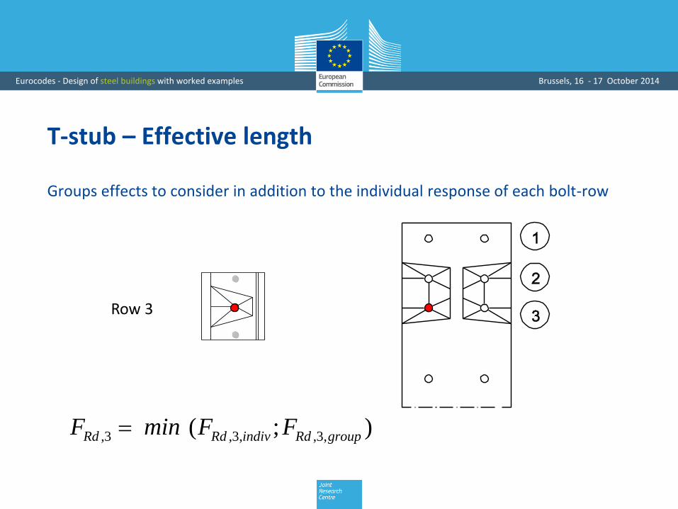
T-stub – Effective length
Groups effects to consider in addition to the individual response of each bolt-row
Row 3
,3 ,3, ,3, ;( )Rd Rd indiv Rd groupF min F F

Eurocodes - Design of steel buildings with worked examples Brussels, 16 - 17 October 2014
Bolt rows consideredIn this example: only bolt row 1 is considered for tension forces
+ +
+ +
M
V
15
3
IPE220
HEB140
120
60 10
8030 30
240
4 M16 8.8
140
u=10p=60
5
w=
Row 1
Row 2
Eurocodes - Design of steel buildings with worked examples Brussels, 16 - 17 October 2014
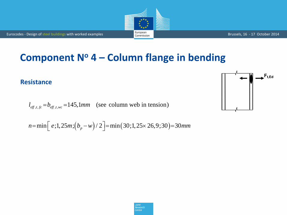
Component No 4 – Column flange in bending
, , , , 145,1 (see column web in tension)eff t fc eff t wcl b mm
min ;1,25 ; / 2 min 30;1,25 26,9;30 30pn e m b w mm
Resistance

Eurocodes - Design of steel buildings with worked examples Brussels, 16 - 17 October 2014
3, , , , 3
, , 2
2 2 2 145,1 8460 2 90,4 10 3010 138,5
26,9 30
eff t fc pl fc t Rd
fc Rd t
l m B nF kN
m n
, , 3 ,2 2 90,43 180,9fc Rd t t RdF B kN
Mode 1 - Complete yielding of the flange
Mode 2 - Bolt failure with yielding of the flange
Mode 3 - Bolt failure
Component No 4 – Column flange in bending
, , , 3
, , 1
4 4 145,1 846010 182,5
26,9
eff t fc pl fc
fc Rd t
l mF kN
m

Eurocodes - Design of steel buildings with worked examples Brussels, 16 - 17 October 2014
Component No 4 – Column flange in bending
,4 , , 1 , , 2 , , 3min ; ; 138,5Rd fc Rd t fc Rd t fc Rd tF F F F kN
3 3, ,
4 3 3
0,9 0,9 145,1 1211,59
26,9
eff fc t fcl tk mm
m
Resistance
Stiffness coefficient

Eurocodes - Design of steel buildings with worked examples Brussels, 16 - 17 October 2014
Component No 5 – End plate in bending
, , min 2 ; min 2 33,66; 5,5 33,66 185eff t p p pl m m mm
min ;1,25 ; min 30;1,25 33,66;30 30p p pn e m e mm
, , , 3
, ,1
4 4 185 13.218Mode 1: 10 291
33,66
eff t p pl p
ep Rd
p
l mF kN
m
3, , , , 3
, ,2
2 2 2 185 13.218 2 90,43 10 30Mode 2: 10 162,1
33,66 30
eff p t pl p t Rd p
ep Rd
p p
l m B nF kN
m n
,5 , ,1 , ,2 , ,3min ; ; 162,1Rd ep Rd ep Rd ep RdF F F F kN
Resistance

Eurocodes - Design of steel buildings with worked examples Brussels, 16 - 17 October 2014
Component No 5 – End plate in bending
3 3, ,
5 3 3
0,9 0,9 185,0 1514,73
33,66
eff t p p
p
l tk mm
m
Stiffness coefficient

Eurocodes - Design of steel buildings with worked examples Brussels, 16 - 17 October 2014
Component No 7 – Beam flange and web in compression
,7 , 3
67,07/ 318,2
210,8 10Rd c Rd b fbF M h t kN
7k
Resistance
Stiffness coefficient
Eurocodes - Design of steel buildings with worked examples Brussels, 16 - 17 October 2014
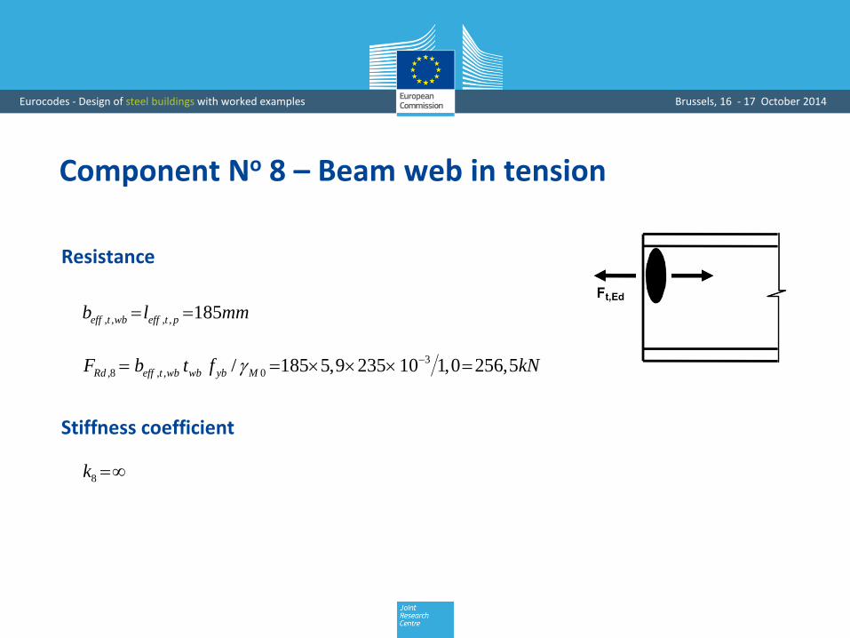
Component No 8 – Beam web in tension
, , , , 185eff t wb eff t pb l mm
3
,8 , , 0/ 185 5,9 235 10 1,0 256,5Rd eff t wb wb yb MF b t f kN
8k
Resistance
Stiffness coefficient

Eurocodes - Design of steel buildings with worked examples Brussels, 16 - 17 October 2014
Component No 10 – Bolts in tension
,10 ,2 2 90,43 180,9Rd t RdF B kN
10
1571,6 1,6 5,30
47,4
s
b
Ak mm
L
Mode 3 in T-stubs for components:
• “column flange in bending”
• “end plate in bending”
Resistance
Stiffness coefficient

Eurocodes - Design of steel buildings with worked examples Brussels, 16 - 17 October 2014
Mj,Rd
Design moment resistance
,min 138,5 (Column flange in bending)Rd Rd iF F kN
3
, 138,5 165,4 10 22,91j Rd RdM F z kNm
, , ,
215,27
3j el Rd j RdM M kNm
Design plastic moment resistance
Relevant component
Design elastic moment resistance
Eurocodes - Design of steel buildings with worked examples Brussels, 16 - 17 October 2014
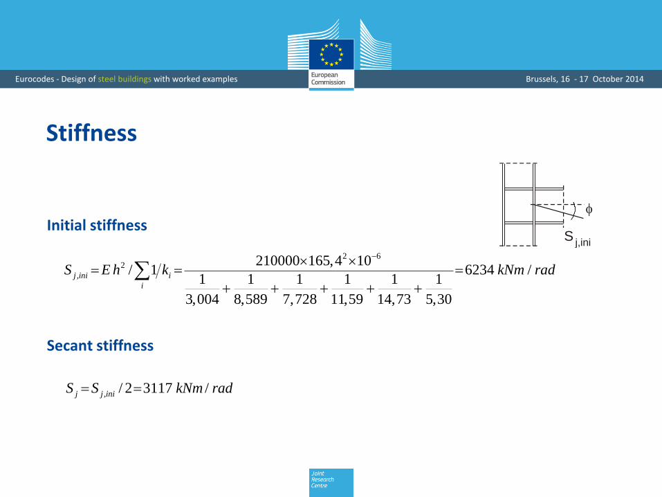
Stiffness
Sj,ini
2 62
,
210000 165,4 10/ 1 6234 /
1 1 1 1 1 1
3,004 8,589 7,728 11,59 14,73 5,30
j ini i
i
S E h k kNm rad
, / 2 3117 /j j iniS S kNm rad
Initial stiffness
Secant stiffness

Eurocodes - Design of steel buildings with worked examples Brussels, 16 - 17 October 2014
Design moment-rotation characteristic
M
Sj,ini
Sj,ini
Sj
Sj= /
Ersatzsteifigkeit:
M j,Rd
2/3Mj,Rd
Secant stiffness

Design of Structural Steel Joints
• Introduction
• Integration of joints into structural design process
• Moment resistant joints
• Simple joints• Design tools

Eurocodes - Design of steel buildings with worked examples Brussels, 16 - 17 October 2014
Nominally pinned joints
Braced frame

Eurocodes - Design of steel buildings with worked examples Brussels, 16 - 17 October 2014
Nominally pinned joints
V 0 M = 0

Eurocodes - Design of steel buildings with worked examples Brussels, 16 - 17 October 2014
Design of simple joints
ECCS Publication No 126 (EN)
• Background information
• Design guidelines
Eurocodes - Design of steel buildings with worked examples Brussels, 16 - 17 October 2014
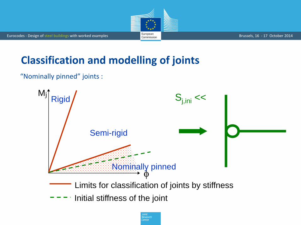
Classification and modelling of joints
Limits for classification of joints by stiffness
Nominally pinned
Semi-rigid
RigidMj
Initial stiffness of the joint
Sj,ini <<
“Nominally pinned” joints :

Eurocodes - Design of steel buildings with worked examples Brussels, 16 - 17 October 2014
Classification and modelling of joints
Sj,ini
Limits for classification of joints by stiffness
Nominally pinned
Semi-rigid
RigidMj
Initial stiffness of the joint
“Semi-rigid” joints :

Eurocodes - Design of steel buildings with worked examples Brussels, 16 - 17 October 2014
Classification and modelling of joints
As an alternative to a semi-continuous modelling (semi-rigid joints), is it safe to
model the joints as nominally pinned whilst they are actually semi-rigid?
Semi-rigid Sj,ini > 0,5EIb/Lb
Partial strength Mj,Rd > 0,25 Mfull-strength
Nominally pinned Sj,ini = 0
Nominally pinned Mj,Rd = 0??

Eurocodes - Design of steel buildings with worked examples Brussels, 16 - 17 October 2014
Classification and modelling of joints
Yes, …under the reservation the joint has:
• a sufficient rotation capacity
= capacity to “rotate”
• a sufficient ductility
= capacity to follow the actual
loading path in a ductile way
VRd
V
M
Yielding criterionMRd
Supposed
loading path
Actual loading
path

Eurocodes - Design of steel buildings with worked examples Brussels, 16 - 17 October 2014
Supplementary design requirement
Sufficient resistance to «catenary effects» so as to provide required structural
robustness

Eurocodes - Design of steel buildings with worked examples Brussels, 16 - 17 October 2014
Example: Partial depth end-plate
Components
• Bolts in shear
• End-plate in bearing
• End-plate in shear (gross section)
• End-plate in shear (net section)
• End-plate in shear block
• End-plate in bending
• Beam web in shear
• Welds in shear
• Column flange in bearing

Eurocodes - Design of steel buildings with worked examples Brussels, 16 - 17 October 2014
Partial depth end-plate
Strength requirement
• Use of “component method” for the assessment of VRd
Assessment of the strength of all the constitutive components of the joint
+
“Assembly” of these components

Eurocodes - Design of steel buildings with worked examples Brussels, 16 - 17 October 2014
Partial depth end-plate
Rotation capacity requirement
Bending moment
Rotationavail
Contact between supported beam and supporting element
Compression force
Bendingmoment
Bolts in tension
Eurocodes - Design of steel buildings with worked examples Brussels, 16 - 17 October 2014
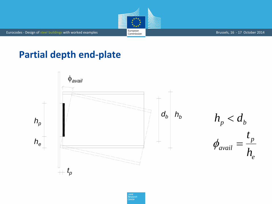
Partial depth end-plate
Rotation capacity requirement
hp
he
tp
hbdb
avail
p bh d
p
avail
e
t
h

Eurocodes - Design of steel buildings with worked examples Brussels, 16 - 17 October 2014
Partial depth end-plate
Ductility requirement
• Prevent premature fracture of the bolts
• Prevent premature fracture of the welds
under unavoidable bending moment in the joint

Eurocodes - Design of steel buildings with worked examples Brussels, 16 - 17 October 2014
Partial depth end-plate
Ductility requirements
• Prevent premature collapse of the bolts
2,8yp
p ub
fd
t f
2,8ycf
p ub
fd
t f for the supporting column
d and fub : diameter and tensile strength of bolts
for the end-plate
Yielding of end-plate prior to tensile fracture of bolts

Design of Structural Steel Joints
• Introduction
• Integration of joints into structural design process
• Moment resistant joints
• Simple joints
• Design tools

Eurocodes - Design of steel buildings with worked examples Brussels, 16 - 17 October 2014
Practical design tools
• Tables of standardized joints
• Dedicated software

Eurocodes - Design of steel buildings with worked examples Brussels, 16 - 17 October 2014
Worked Example Configuration Beam IPE 500 Column HEA 340 End plate connection
Design assumption Rigid joint
Frame analysisMEd = 220 kNm
CoP software used for this example: http://cop.fw-ing.com

Eurocodes - Design of steel buildings with worked examples Brussels, 16 - 17 October 2014
Design resistance: MRd = 196 kNm < 220 kNmClassification: Semi-rigidFailure mode: Column web in compression

Eurocodes - Design of steel buildings with worked examples Brussels, 16 - 17 October 2014
Failure mode:End plate in bending

Eurocodes - Design of steel buildings with worked examples Brussels, 16 - 17 October 2014
Failure mode:Column web panel in shear

Eurocodes - Design of steel buildings with worked examples Brussels, 16 - 17 October 2014
Failure mode:Column web panel in shear

Eurocodes - Design of steel buildings with worked examples Brussels, 16 - 17 October 2014
Failure mode:Column web panel in shear

Design of Structural Steel Joints
Dr. Klaus WeynandFeldmann + Weynand GmbH, Aachen, Germany
Prof. Jean-Pierre JaspartUniversity of Liège, Belgium
Top Related