


Languages
Pages
Legal

Bray/McCannalok CryogenicHigh Performance Butterfly Valve
Operation and Maintenance Manual
Bray/McCannalok Cryogenic Valve Operation and Maintenance Manual
Table of Contents
Definition of Terms 1
Introduction 1
Installation 2
Maintenance 3
Stem Seal Replacement 4
Seat Replacement 5
Disc and Stem Replacement 6
Parts Diagram - Bray/McCannalok Cryogenic Valve 8
Parts Diagram - Bray/McCannalok Low Temperature Valve 9
Field Adjustments - All Valves 10
For information on this product and other Bray products please visit us at our web page - www.bray.com.
1
Bray/McCannalok Cryogenic Valve Operation and Maintenance Manual
Read and Follow These Instructions
Save These InstructionsDEFINITION OF TERMS
indicates a potentially hazardous situation which, if not avoided, could result in death or serious injury
indicates a potentially hazardous situation which, if not avoided, may result in minor or moderate injury
NOTICE used without the safety alert symbol indicates a potential situation which, if not avoided, may result in an undesirable result or state, including property damage
INTRODUCTION
The Bray/McCannalok Cryogenic high-performance butterfly valve combines the advantages of trunnion-type ball valves with the easy operation, light weight, and low cost of butterfly valves One basic design is suitable for a wide range of services, including liquid oxygen, LNG and air separation.
Features include:
• Tight shutoff provided throughout a wide range of operating conditions
• Suitable for both modulating and on/off services, the Bray/McCannalok butterfly valve is easily automated with your choice of manual operators, electric and pneumatic actuators, positioners, and controls
Additional information about Bray/McCannalok butterfly valves – including application data, engineering specifications, and actuator selection is available from your Bray distributor or sales representative.
2
Bray/McCannalok Cryogenic Valve Operation and Maintenance Manual
INSTALLATION
1 The Bray/McCannalok valve is designed to be mounted between ANSI flanges When the valve is open, the disc will extend into the pipe on both sides of the valve – further on the body side than the seat retainer side of the valve Piping must be large enough to allow the disc to clear the pipe The charts on page 3 show the minimum pipe ID allowable, and standard pipe IDs
In general, Class 150 valves will clear Schedule 40 pipe, and Class 300 valves will clear Schedule 80 pipe adequately
2 If handle or actuator has been removed do not rotate disc beyond full open or closed position – this could cause damage to sealing surfaces
NOTE: Bray/McCannalok valves are equipped with travel limiters to prevent over closure The valve is opened by turning counterclockwise, closed by turning clockwise The double “D” flats or keyway at the top of the stem is parallel to the disc edge
3 Verify and check the preferred flow direction prior to installation
Positive shutoff will be obtained with the valve in either position; however, installation with the seat retainer upstream will give longer service life, especially in erosive services
4 With the disc in closed position, carefully center valve between flanges Guide holes (wafer pattern valve) or tapped holes (lugged valves) to match ANSI Pipe flanges and assist in positive alignment
5 Use standard torques when bolting valve into the line The seat is sufficiently compressed by the seat retainer, and additional force from flange bolting is not required
6 Gaskets should conform to the requirements of API Standard 601, Edition 3 for ASME/ANSI B16 5 class flanges Spiral wound gaskets, such as Flexitallic CG or CGl series, conforming to ASME/ANSI B16 20 are acceptable
3
Bray/McCannalok Cryogenic Valve Operation and Maintenance Manual
MAINTENANCE1 Reasonable precautions should be taken before
beginning work on the valve Protective clothing, as required by the specific line fluid, should be worn
Before removing handle or the actuator from the valve, or before removing seat retainer from a valve in dead end service, close the valve and depressurize the line
2 The eccentric design of the Bray/McCannalok may allow line pressure to open the valve if the handle/actuator is not in place while the valve is under pressure
Do not pressurize the line without a handle or actuator on the valve
3 The Bray/McCannalok valve must be in the closed position to be removed from the line
4 Begin all work on a valve that has been removed from the line by cleaning the valve, removing any grit or scale
When handling the valve, care should be taken not to scratch the disc edge or seat
5 Replacement seats, seals and other parts are available from authorized distributors Contact your distributor or sales representative for details of price and delivery
Verify if the valves are required to be cleaned for oxygen service Depending on the application, the valves may need to be cleaned and assembled at a qualified oxygen cleaning facility
NOTES:
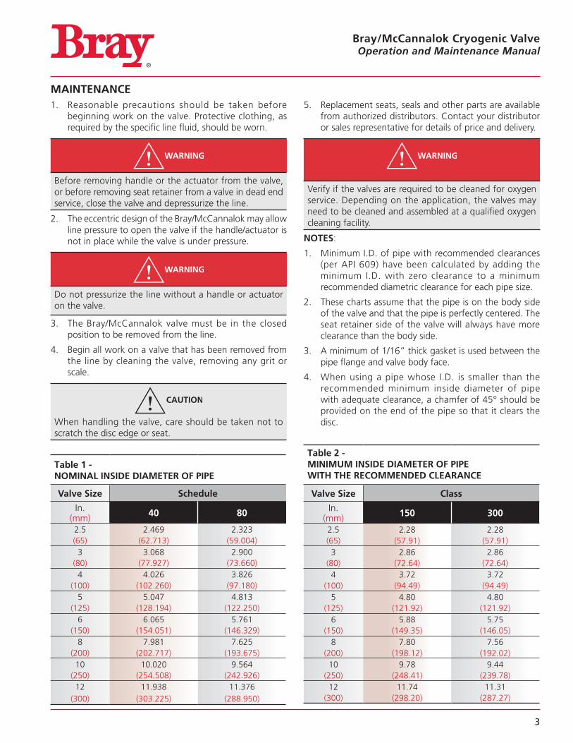
1 Minimum I D of pipe with recommended clearances (per API 609) have been calculated by adding the minimum I D with zero clearance to a minimum recommended diametric clearance for each pipe size
2 These charts assume that the pipe is on the body side of the valve and that the pipe is perfectly centered The seat retainer side of the valve will always have more clearance than the body side
3 A minimum of 1/16” thick gasket is used between the pipe flange and valve body face
4 When using a pipe whose I D is smaller than the recommended minimum inside diameter of pipe with adequate clearance, a chamfer of 45° should be provided on the end of the pipe so that it clears the disc
Table 1 - NOMINAL INSIDE DIAMETER OF PIPE
Valve Size Schedule
In (mm) 40 80
2 5 2 469 2 323(65) (62 713) (59 004)3 3 068 2 900
(80) (77 927) (73 660)4 4 026 3 826
(100) (102 260) (97 180)5 5 047 4 813
(125) (128 194) (122 250)6 6 065 5 761
(150) (154 051) (146 329)8 7 981 7 625
(200) (202 717) (193 675)10 10 020 9 564
(250) (254 508) (242 926)12 11 938 11 376
(300) (303 225) (288 950)
Table 2 - MINIMUM INSIDE DIAMETER OF PIPE WITH THE RECOMMENDED CLEARANCE
Valve Size Class
In (mm) 150 300
2 5 2 28 2 28(65) (57 91) (57 91)3 2 86 2 86
(80) (72 64) (72 64)4 3 72 3 72
(100) (94 49) (94 49)5 4 80 4 80
(125) (121 92) (121 92)6 5 88 5 75
(150) (149 35) (146 05)8 7 80 7 56
(200) (198 12) (192 02)10 9 78 9 44
(250) (248 41) (239 78)12 11 74 11 31
(300) (298 20) (287 27)
4
Bray/McCannalok Cryogenic Valve Operation and Maintenance Manual
STEM SEAL REPLACEMENT
Refer to drawings on page 9 and page 8 for parts identification
1 If required, remove handle assembly Remove socket head cap screws (8) and lock washers (7) Remove mounting bracket (9) For actuated valves, unbolt mounting bracket from body and lift actuator assembly off stem
NOTICE
Note assembly positions before removal
2 Remove gland retainer nuts (18) and lock washers (17) Remove gland retainer (15) anti-blowout retaining ring or split ring (14) (depending on size), grounding washer (12) and gland ring (13)
3 Hook out stem seals (11)
When handling stem seals, care should be taken not to scratch stem or stuffing box bore
Do not remove thrust washer (10), unless further valve disassembly is required
4 Examine stuffing box bore and stem, clean as necessary to remove any corrosion or foreign matter before installing new seals
5 Install new seals in stuffing box one at a time Stagger seal ring joints 180° apart when installing Tamp each ring to bottom before installing next ring
6 Install grounding washer (12) on top of the stem seals with the tangs facing down
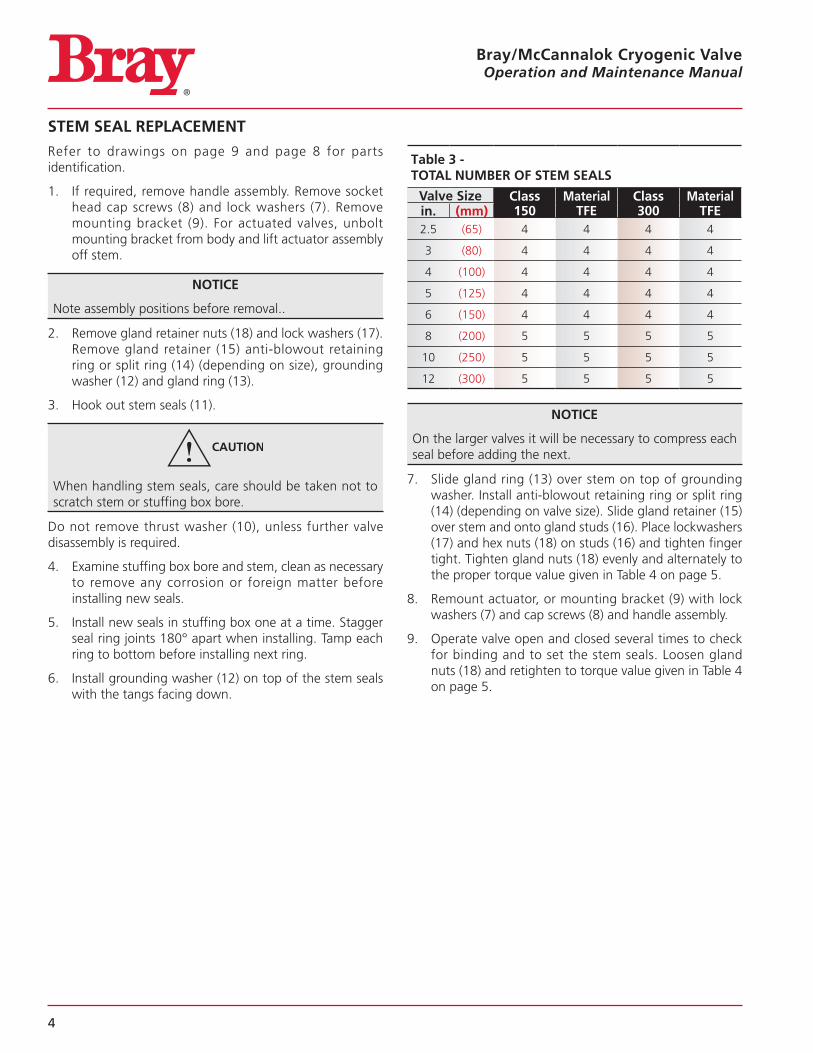
Table 3 - TOTAL NUMBER OF STEM SEALS
Valve Size Class 150
Material TFE
Class 300
Material TFEin. (mm)
2 5 (65) 4 4 4 4
3 (80) 4 4 4 4
4 (100) 4 4 4 4
5 (125) 4 4 4 4
6 (150) 4 4 4 4
8 (200) 5 5 5 5
10 (250) 5 5 5 5
12 (300) 5 5 5 5
NOTICE
On the larger valves it will be necessary to compress each seal before adding the next
7 Slide gland ring (13) over stem on top of grounding washer Install anti-blowout retaining ring or split ring (14) (depending on valve size) Slide gland retainer (15) over stem and onto gland studs (16) Place lockwashers (17) and hex nuts (18) on studs (16) and tighten finger tight Tighten gland nuts (18) evenly and alternately to the proper torque value given in Table 4 on page 5
8 Remount actuator, or mounting bracket (9) with lock washers (7) and cap screws (8) and handle assembly
9 Operate valve open and closed several times to check for binding and to set the stem seals Loosen gland nuts (18) and retighten to torque value given in Table 4 on page 5
5
Bray/McCannalok Cryogenic Valve Operation and Maintenance Manual
SEAT REPLACEMENT
Refer to drawings on page 9 and page 8 for parts identification With the disc in the closed position, remove the valve from the line
1 Lay the valve down with the disc in the closed position and the seat retainer side facing up
2 Remove the socket head cap screws (24), the seat retainer (23), and seat (21)
3 Carefully clean the seat area in the body and seat retainer Remove foreign matter, dirt, oil, etc Check disc seating area for nicks or scratches
4 With the disc in the CLOSED position, place the new seat (21) on disc (2), carefully centering it in the recess in the body
5 Align the holes in the seat retainer (23) with matching holes in body and carefully place in position on top of seat (21)
6 Install the retainer gasket
7 Place seat retainer over seat with seat retainer bolt counterbore facing away from the face of the body
Do not shift the retainer in order to align holes It may shift the seat from its correct position
8 Make sure that the seat remains centered with body when positioning seat retainer
9 Wrap the thread of the socket head cap screws with white PTFE/Teflon tapes in a clockwise position
Step 1: Install the socket head cap screws finger tight to the body through the seat retainer counter bores
Step 2: Tighten the cap screws to approximately 30% of the torque value listed in Table 4 on page 5 in a crisscross pattern
Step 3: Repeat Step 2, increasing the torque value to approximately 60% of the final torque value
Step 4: Repeat Step 3, increasing the torque value to the final required torque value
Step 5: Open the disc Re-torque all cap screws to the final required torque value
10 A final tightening should be checked prior to installation Operate valve several times and examine seat for any damage before reinstalling the valve in the line
11 Operate valve several times and examine seat for any damage before reinstalling the valve in the line
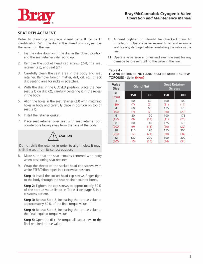
Table 4 - GLAND RETAINER NUT AND SEAT RETAINER SCREW TORQUES - Lb-in (N•m)
Valve Size
Gland NutSeat Retainer
Screwsin
(mm)150 300 150 300
3 60 60 100 100(80) (7) (7) (11) (11)4 60 60 175 175
(100) (7) (7) (20) (20)6 80 120 100 175
(150) (9) (14) (11) (20)8 80 140 175 175
(200) (9) (16) (20) (20)10 110 190 175 300
(250) (12) (21) (20) (34)12 130 220 300 300
(300) (15) (25) (34) (34)
6
Bray/McCannalok Cryogenic Valve Operation and Maintenance Manual
DISC AND STEM REPLACEMENT
Refer to drawings on page 9 and page 8 for parts identification
NOTICE
Stem and disc are supplied as a matched set with taper pins and are to be replaced as a set
1 For handle-operated valves remove handle assembly Remove socket head cap screws (8) and lock washers (7) Remove mounting bracket (9) For actuated valves, unbolt mounting bracket from body and lift actuator assembly off stem
NOTICE
Note assembly positions before removal
2 Remove gland retainer nuts (18) and lock washers (7) Remove gland retainer (15), anti-blowout retaining ring or split ring (14) (depending on valve size), grounding washer (12) and gland ring (13)
3 Hook out stem seals (11)
Take care not to scratch stem or stuffing box bore
4 Remove locating plug (20) and gasket (19)
5 Remove cap screws (24), seat retainer (23), and seat (21)
6 Turn disc to the full open position and drill out tack welds on large end of taper pins (4)
Take care to support valve so that disc surfaces are not scratched
Drill sizes to remove tack welds as given in Table 5 on page 7 Use center-punch to dimple center of tack welds prior to drilling
7 Place valve in flat position, with flat face of disc up Support disc and body on wooden blocks to protect disc and body surfaces Disc will rest in partially open position
8 Knock out taper pins (4) using a rod or punch on small end of pin (opposite tack weld) It may be necessary to lift body and rotate disc slightly to do this Make sure disc is resting on wood block since it will swing freely
on stem with pins removed When pins (4) are out, lay body down so disc and body are evenly supported on flat surface to lift body and rotate disc slightly to do this Make sure disc is resting on wood block since it will swing freely on stem with pins removed When pins (4) are out, lay body down so disc and body are evenly supported on flat surface
9 Using a brass bar or drift punch, knock stem (3) loose and pull from body After long or severe service this may take considerable force Be careful not to damage bearings, spacers or body
Be careful not to damage bearings, spacers or body
Disc spacers (5) are used at top and bottom of disc to properly position disc in body Proper spacers were selected at initial assembly and rarely require replacement The location of these spacers should be noted, and the spacers marked at disassembly so that they are reinstalled in the same positions, top and bottom
10 Separate body from disc, and remove thrust washer (10) from packing bore
11 Examine stem bearings (6) for excessive wear If removed from body, note position and mark to reinstall in same location If bearing liner is worn through to the shell, or severe damage is evident they should be replaced Replacement is rarely needed
12 Clean body thoroughly to remove all dirt, foreign matter, rust, etc
13 Place the body (1) flat, seat retainer side up, and support it on wooden blocks sufficiently above the work surface as to facilitate insertion of the disc (2) in open position Lower the disc into position, aligning the bores in body and disc
14 Insert new stem (3) in body (1) with large end of the taper pin holes toward the top Assemble disc spacers (5) as stem (3) is inserted, making sure that spacers are returned to original locations as marked
15 Align taper pin holes in disc and stem, and install taper pins (4) Drive pins in tightly with rod or punch, and tack weld each pin (4) to disc (2) at large end of pin
16 Install new gasket (19) on locating plug (20) and install plug in body
7
Bray/McCannalok Cryogenic Valve Operation and Maintenance Manual
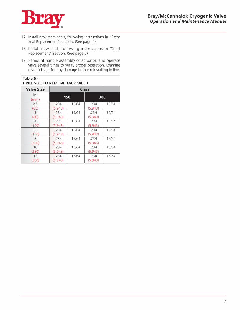
17 Install new stem seals, following instructions in “Stem Seal Replacement” section (See page 4)
18 Install new seat, following instructions in “Seat Replacement” section (See page 5)
19 Remount handle assembly or actuator, and operate valve several times to verify proper operation Examine disc and seat for any damage before reinstalling in line
Table 5 - DRILL SIZE TO REMOVE TACK WELD
Valve Size Classin
(mm)150 300
2 5 234 15/64 234 15/64(65) (5 943) (5 943)3 234 15/64 234 15/64
(80) (5 943) (5 943)4 234 15/64 234 15/64
(100) (5 943) (5 943)6 234 15/64 234 15/64
(150) (5 943) (5 943)8 234 15/64 234 15/64
(200) (5 943) (5 943)10 234 15/64 234 15/64
(250) (5 943) (5 943)12 234 15/64 234 15/64
(300) (5 943) (5 943)
8
Bray/McCannalok Cryogenic Valve Operation and Maintenance Manual
89
18
17 15
16 14
13
12
11
10
6
25
7
3
4
5
5
21
22
23
2
6
19
20
1
24
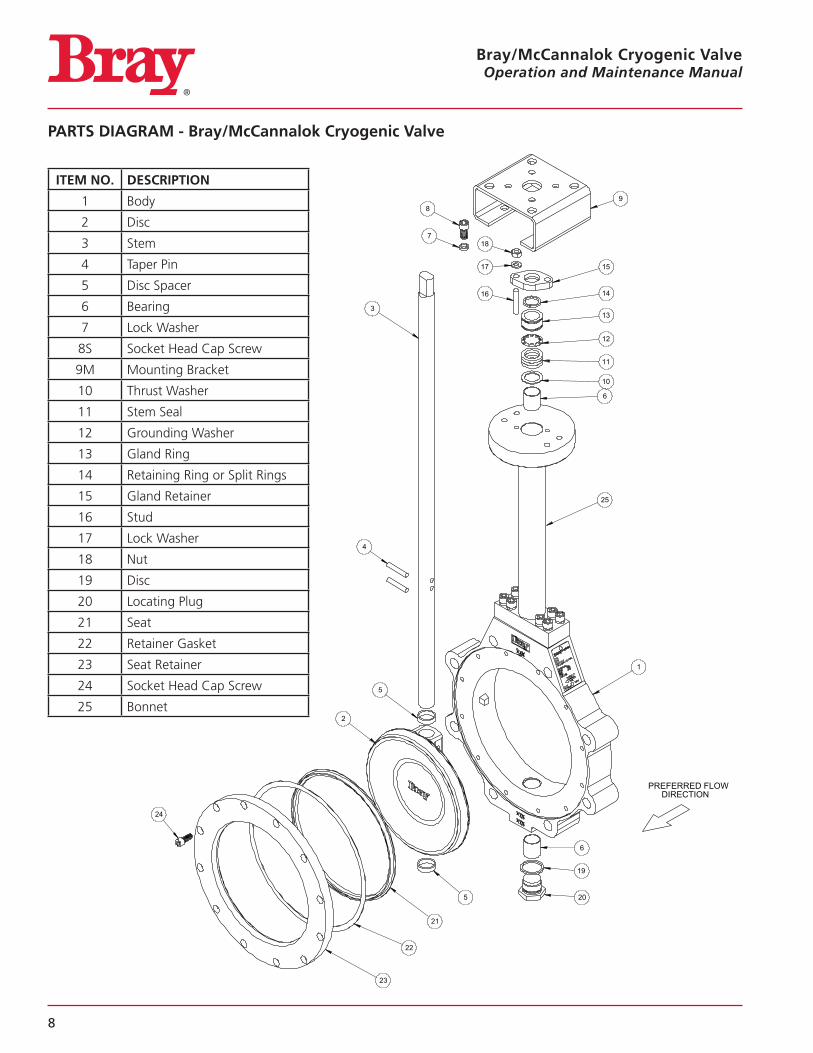
PREFERRED FLOWDIRECTION
ITEM NO. DESCRIPTION
1 Body
2 Disc
3 Stem
4 Taper Pin
5 Disc Spacer
6 Bearing
7 Lock Washer
8S Socket Head Cap Screw
9M Mounting Bracket
10 Thrust Washer
11 Stem Seal
12 Grounding Washer
13 Gland Ring
14 Retaining Ring or Split Rings
15 Gland Retainer
16 Stud
17 Lock Washer
18 Nut
19 Disc
20 Locating Plug
21 Seat
22 Retainer Gasket
23 Seat Retainer
24 Socket Head Cap Screw
25 Bonnet
PARTS DIAGRAM - Bray/McCannalok Cryogenic Valve
9
Bray/McCannalok Cryogenic Valve Operation and Maintenance Manual
3
89
7
16
15
14
13
12
11
10
4
1
2
19
5
21
23
24
17
18
6
5
6
22
20
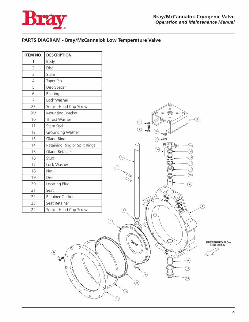
PREFERRED FLOWDIRECTION
ITEM NO. DESCRIPTION
1 Body
2 Disc
3 Stem
4 Taper Pin
5 Disc Spacer
6 Bearing
7 Lock Washer
8S Socket Head Cap Screw
9M Mounting Bracket
10 Thrust Washer
11 Stem Seal
12 Grounding Washer
13 Gland Ring
14 Retaining Ring or Split Rings
15 Gland Retainer
16 Stud
17 Lock Washer
18 Nut
19 Disc
20 Locating Plug
21 Seat
22 Retainer Gasket
23 Seat Retainer
24 Socket Head Cap Screw
PARTS DIAGRAM - Bray/McCannalok Low Temperature Valve
Bray/McCannalok Cryogenic Valve Operations and Maintenance Manual
FIELD ADJUSTMENTS - ALL VALVES
Stem Seal Leakage – Should leakage occur at the stem seals, it may be stopped by retightening the gland retainer nuts to the values specified in Table 4 on page 5
NOTICE
Do not overtighten gland nuts, as this may cause increased operating torque and improper valve operation or closure
If the leakage cannot be stopped by this action, the stem seals require replacement
Adjusting Valve Closure – Valves with gear actuators or electric/pneumatic actuators may require adjustment of the travel stops in the actuator to properly close valve for tight shut-off The following procedure should be followed to set travel or limit stops
(It is recommended that the valve must be removed from line for this procedure and actuator mounting )
1 Using a straight-edge and vernier or depth caliper, measure the distances from the face of the seat retainer to the disc (valve closed) face at the 3 o’clock and 9 o’clock positions (stem is at 12 o’clock position) The measurements must agree within 1/16” (0 062”)
2 If they do not agree, disc must be rotated in the direction of the larger dimension If the 3 o’clock dimension is larger, the disc is not fully closed, and must be rotated in the “close” direction more If 9 o’clock dimension is larger, disc is over-closed, and must be opened slightly
3 The valve disc is at the full open position when the disc is perpendicular to the body Set the “open” actuator stop for this position
Do not allow the valve to over-open as this may damage the disc seating surfaces by hitting body or attached piping
4 On gear operators, loosen and adjust the closing stop screw to permit proper disc positioning Adjust and lock down when disc closure is within measured tolerance in step 1 Open and close valve; recheck measurements before reinstalling in line
NOTICE
The setting of the actuation device’s close travel stop is important
The valve has an internal travel limiter to ensure valve disc cannot be over closed
To ensure that the valve travel limiter is not damaged, the actuator close travel stop bolt must be at a position just before valve disc contacts it’s travel limiter
5 For other power actuators, consult the manufacturer’s instructions for setting travel stops, as these vary with actuator model and type
6 If removing the valve from the line is not practical, as a crude remedy the disc can be placed into a position in the seat at which the leakage stops and travel stops are adjusted to this position
All statements, technical information, and recommendations in this bulletin are for general use only Consult Bray representatives or factory for the specific requirements and material selection for your intended application The right to change or modify product design or product without prior notice is reserved Patents issued and applied for worldwide
Bray® is a registered trademark of Bray International, Inc © 2016 Bray International, Inc All rights reserved
OM_Bray/McCannalok Cryogenic_08_22_2016
Bray ControlsA Division of Bray International, Inc.13333 Westland East Blvd.Houston, Texas 77041Tel: 281.894.5454 • www.bray.com
Top Related