Bray/McCannalok High Performance Butterfly ….…High Performance Butterfly Valve Operation and...
14
Bray/McCannalok High Performance Butterfly Valve Operation and Maintenance Manual
Transcript of Bray/McCannalok High Performance Butterfly ….…High Performance Butterfly Valve Operation and...
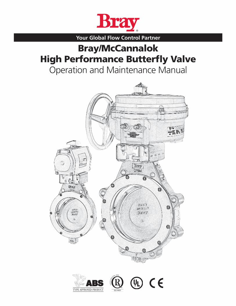
Bray/McCannalokHigh Performance Butterfly Valve
Operation and Maintenance Manual
Table of Contents
Definition of Terms 1
Introduction 1
Installation 1
Maintenance 2
Stem Seal Replacement 4
Seat Replacement 4
Disc and Stem Replacement 5
Parts Diagram - Standard 7
Parts Diagram - Metal Seated 8
Parts Diagram - Fire Safe 9
Special Instructions Bray/McCannalok Fire Safe and Metal Seated Installation 10
Stem Seal Replacement 10
Seat Replacement 10
Disc and Stem Replacement 11
Field Adjustments – All Valves 11
For information on this product and other Bray products please visit us at our web page - www.bray.com.
Bray/McCannalok Operations and Maintenance Manual
1
Bray/McCannalok Operations and Maintenance Manual
Read and Follow These InstructionsSave These Instructions
INTRODUCTIONThe Bray/McCannalok high-performance butterfly valve combines the advantages of trunnion-type ball valves with the easy operation, light weight, and low cost of butterfly valves One basic design is suitable for a wide range of ser-vices, including oxygen, chlorine, sour gas, vacuum, and steam applications
Features Include:
• Bubble tight shutoff provided throughout a wide range of operating conditions
• Suitable for both modulating and on/off services, the Bray/McCannalok butterfly valve is easily automated with your choice of manual operators, electric and pneumatic actuators, positioners, and controls
• The Bray/McCannalok is available in a Fire Safe model qualified to API 607 5th Edition and BS 6755 Part 2
• The Bray/McCannalok is also available in a Metal Seated only model providing IEC 60534-4 Class IV bi-directional leakage rates through full pressure range
Additional information about Bray/McCannalok butterfly valves – including application data, engineering specifica-tions, and actuator selection is available from your Bray distributor or sales representative
INSTALLATIONSpecial instructions for Fire Safe and Metal Seated valves appear on page 10
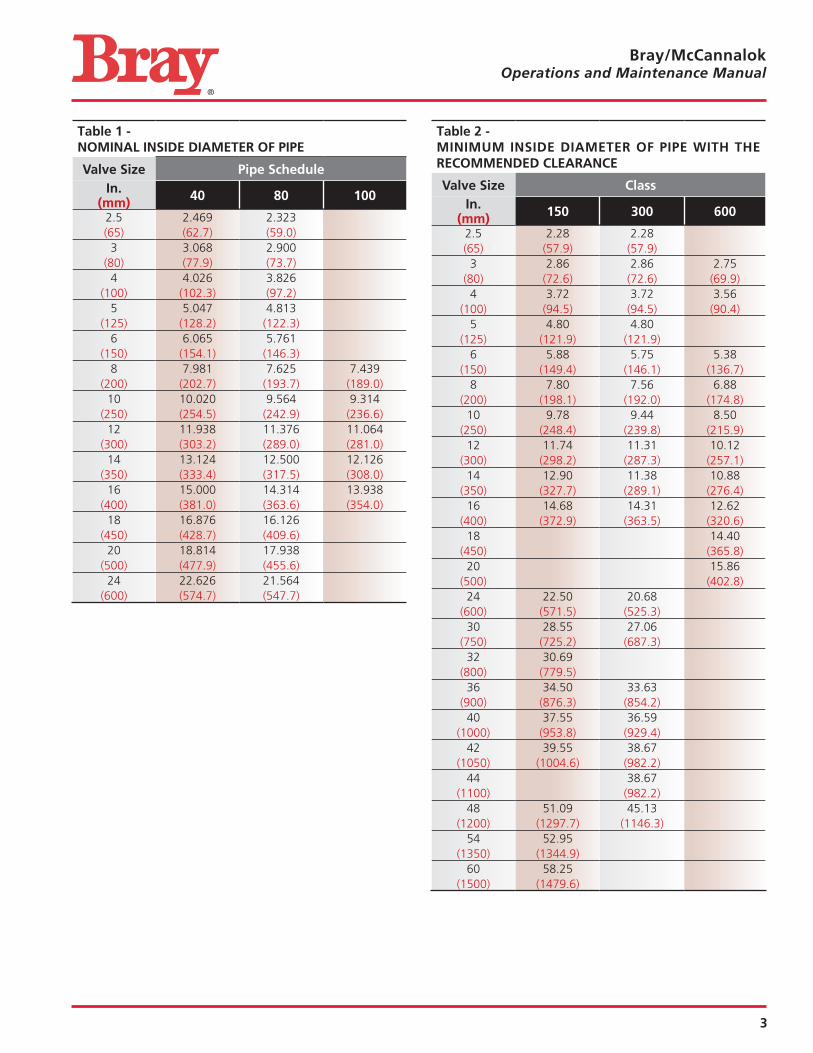
1 The Bray/McCannalok valve is designed to be mounted between ANSI flanges When the valve is open, the disc will extend into the pipe on both sides of the valve – further on the body side than the seat retainer side of the valve Piping must be large enough to allow the disc to clear the pipe Tables 1 and 2 on page 3 show the minimum pipe ID allowable, and standard pipe IDs In general, Class 150 valves will clear Schedule 40
pipe, and Class 300 valves will clear Schedule 80 pipe adequately Class 600 will in general clear Schedule 80 sizes 3, 4, and 6; and Schedule 100 in sizes 8, 10, 12, 14, and 16
2 If handle or actuator has been removed do not rotate disc beyond full open or closed position – this could cause damage to sealing surfaces
NOTE: Bray/McCannalok valves are equipped with travel limiters to prevent over closure The valve is opened by turning counterclockwise, closed by turning clockwise The double “D” flats or keyway at the top of the stem is paral-lel to the disc edge
NOTICE3 For maximum service life, install the valve with the seat
retainer upstream Positive shutoff will be obtained with the valve in either position; however, installation with the seat retainer upstream will give longer ser-vice life, especially in erosive services
4 With the disc in closed position, carefully center valve between flanges Guide holes (wafer pattern valve) or tapped holes (lugged valves) to match ANSI Pipe flanges and assist in positive alignment
5 Use standard torques when bolting valve into the line The seat is sufficiently compressed by the seat retainer, and additional force from flange bolting is not required
6 Gaskets should conform to the requirements of API Standard 601, Edition 3 for ASME/ANSI B16 5 class flanges Spiral wound gaskets, such as Flexitallic CG or CGl series, conforming to ASME/ANSI B16 20 are acceptable
DEFINITION OF TERMS
indicates a potentially hazardous situation which, if not avoided, could result in death or serious injury
indicates a potentially hazardous situation which, if not avoided, may result in minor or moderate injury
NOTICE used without the safety alert symbol indicates a potential situation which, if not avoided, may result in an undesirable result or state, including property damage
2
Bray/McCannalok Operations and Maintenance Manual
MAINTENANCE1 Reasonable precautions should be taken before begin-
ning work on the valve Protective clothing, as required by the specific line fluid, should be worn
Before removing handle or the actuator from the valve, or before removing seat retainer from a valve in dead end service, close the valve and depressurize the line
2 The eccentric design of the Bray/McCannalok may allow line pressure to open the valve if the handle/actu-ator is not in place while the valve is under pressure
Do not pressurize the line without a handle or actuator on the valve
3 The Bray/McCannalok valve must be in the closed posi-tion to be removed from the line
4 Begin all work on a valve that has been removed from the line by cleaning the valve, removing any grit or scale
When handling the valve, care should be taken not to scratch the disc edge or seat
5 Replacement seats, seals and other parts are available from authorized distributors Contact your distributor or sales representative for details of price and delivery
NOTES:
1 Minimum ID of pipe with recommended clearances (per API 609) have been calculated by adding the minimum ID with zero clearance to a minimum recommended dia-metric clearance for each pipe size
2 These charts assume that the pipe is on the body side of the valve and that the pipe is perfectly centered The seat retainer side of the valve will always have more clearance than the body side
3 A minimum of 1/16” thick gasket is used between the pipe flange and valve body face
4 When using a pipe whose ID is smaller than the rec-ommended minimum inside diameter of pipe with adequate clearance, a chamfer of 45° should be pro-vided on the end of the pipe so that it clears the disc
3
Bray/McCannalok Operations and Maintenance Manual
Table 1 - NOMINAL INSIDE DIAMETER OF PIPE
Valve Size Pipe ScheduleIn.
(mm) 40 80 100
2 5 2 469 2 323(65) (62 7) (59 0)3 3 068 2 900
(80) (77 9) (73 7)4 4 026 3 826
(100) (102 3) (97 2)5 5 047 4 813
(125) (128 2) (122 3)6 6 065 5 761
(150) (154 1) (146 3)8 7 981 7 625 7 439
(200) (202 7) (193 7) (189 0)10 10 020 9 564 9 314
(250) (254 5) (242 9) (236 6)12 11 938 11 376 11 064
(300) (303 2) (289 0) (281 0)14 13 124 12 500 12 126
(350) (333 4) (317 5) (308 0)16 15 000 14 314 13 938
(400) (381 0) (363 6) (354 0)18 16 876 16 126
(450) (428 7) (409 6)20 18 814 17 938
(500) (477 9) (455 6)24 22 626 21 564
(600) (574 7) (547 7)
Table 2 - MINIMUM INSIDE DIAMETER OF PIPE WITH THE RECOMMENDED CLEARANCE
Valve Size ClassIn.
(mm) 150 300 600
2 5 2 28 2 28(65) (57 9) (57 9)3 2 86 2 86 2 75
(80) (72 6) (72 6) (69 9)4 3 72 3 72 3 56
(100) (94 5) (94 5) (90 4)5 4 80 4 80
(125) (121 9) (121 9)6 5 88 5 75 5 38
(150) (149 4) (146 1) (136 7)8 7 80 7 56 6 88
(200) (198 1) (192 0) (174 8)10 9 78 9 44 8 50
(250) (248 4) (239 8) (215 9)12 11 74 11 31 10 12
(300) (298 2) (287 3) (257 1)14 12 90 11 38 10 88
(350) (327 7) (289 1) (276 4)16 14 68 14 31 12 62
(400) (372 9) (363 5) (320 6)18 14 40
(450) (365 8)20 15 86
(500) (402 8)24 22 50 20 68
(600) (571 5) (525 3)30 28 55 27 06
(750) (725 2) (687 3)32 30 69
(800) (779 5)36 34 50 33 63
(900) (876 3) (854 2)40 37 55 36 59
(1000) (953 8) (929 4)42 39 55 38 67
(1050) (1004 6) (982 2)44 38 67
(1100) (982 2)48 51 09 45 13
(1200) (1297 7) (1146 3)54 52 95
(1350) (1344 9)60 58 25
(1500) (1479 6)
4
Bray/McCannalok Operations and Maintenance Manual
STEM SEAL REPLACEMENTRefer to drawing on page 7 for parts identification
1 If required, remove handle assembly Remove socket head cap screws (21) and lock washers (22) Remove mount-ing bracket (20) For actuated valves, unbolt mounting bracket from body and lift actuator assembly off stem
NOTICE
Note assembly positions before removal
2 Remove gland retainer nuts (14) and lock washers (13) Remove gland retainer (11) anti-blowout retaining ring or split ring (10) (depending on size), and gland ring (7)
3 Hook out stem seals (8)
When handling stem seals, care should be taken not to scratch stem or stuffing box bore
Do not remove thrust washer (9), unless further valve disassembly is required
4 Examine stuffing box bore and stem, clean as necessary to remove any corrosion or foreign matter before installing new seals
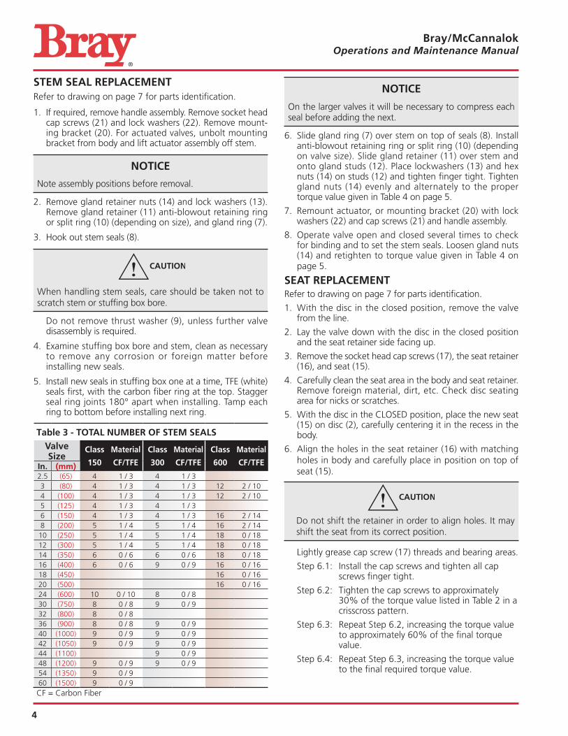
5 Install new seals in stuffing box one at a time, TFE (white) seals first, with the carbon fiber ring at the top Stagger seal ring joints 180° apart when installing Tamp each ring to bottom before installing next ring
Table 3 - TOTAL NUMBER OF STEM SEALS
Valve Size
Class
150
Material
CF/TFE
Class
300
Material
CF/TFE
Class
600
Material
CF/TFEIn. (mm)2 5 (65) 4 1 / 3 4 1 / 33 (80) 4 1 / 3 4 1 / 3 12 2 / 104 (100) 4 1 / 3 4 1 / 3 12 2 / 105 (125) 4 1 / 3 4 1 / 36 (150) 4 1 / 3 4 1 / 3 16 2 / 148 (200) 5 1 / 4 5 1 / 4 16 2 / 1410 (250) 5 1 / 4 5 1 / 4 18 0 / 1812 (300) 5 1 / 4 5 1 / 4 18 0 / 1814 (350) 6 0 / 6 6 0 / 6 18 0 / 1816 (400) 6 0 / 6 9 0 / 9 16 0 / 1618 (450) 16 0 / 1620 (500) 16 0 / 1624 (600) 10 0 / 10 8 0 / 830 (750) 8 0 / 8 9 0 / 932 (800) 8 0 / 836 (900) 8 0 / 8 9 0 / 940 (1000) 9 0 / 9 9 0 / 942 (1050) 9 0 / 9 9 0 / 944 (1100) 9 0 / 948 (1200) 9 0 / 9 9 0 / 954 (1350) 9 0 / 960 (1500) 9 0 / 9CF = Carbon Fiber
NOTICE
On the larger valves it will be necessary to compress each seal before adding the next
6 Slide gland ring (7) over stem on top of seals (8) Install anti-blowout retaining ring or split ring (10) (depending on valve size) Slide gland retainer (11) over stem and onto gland studs (12) Place lockwashers (13) and hex nuts (14) on studs (12) and tighten finger tight Tighten gland nuts (14) evenly and alternately to the proper torque value given in Table 4 on page 5
7 Remount actuator, or mounting bracket (20) with lock washers (22) and cap screws (21) and handle assembly
8 Operate valve open and closed several times to check for binding and to set the stem seals Loosen gland nuts (14) and retighten to torque value given in Table 4 on page 5
SEAT REPLACEMENTRefer to drawing on page 7 for parts identification
1 With the disc in the closed position, remove the valve from the line
2 Lay the valve down with the disc in the closed position and the seat retainer side facing up
3 Remove the socket head cap screws (17), the seat retainer (16), and seat (15)
4 Carefully clean the seat area in the body and seat retainer Remove foreign material, dirt, etc Check disc seating area for nicks or scratches
5 With the disc in the CLOSED position, place the new seat (15) on disc (2), carefully centering it in the recess in the body
6 Align the holes in the seat retainer (16) with matching holes in body and carefully place in position on top of seat (15)
Do not shift the retainer in order to align holes It may shift the seat from its correct position
Lightly grease cap screw (17) threads and bearing areas
Step 6 1: Install the cap screws and tighten all cap screws finger tight
Step 6 2: Tighten the cap screws to approximately 30% of the torque value listed in Table 2 in a crisscross pattern
Step 6 3: Repeat Step 6 2, increasing the torque value to approximately 60% of the final torque value
Step 6 4: Repeat Step 6 3, increasing the torque value to the final required torque value
5
Bray/McCannalok Operations and Maintenance Manual
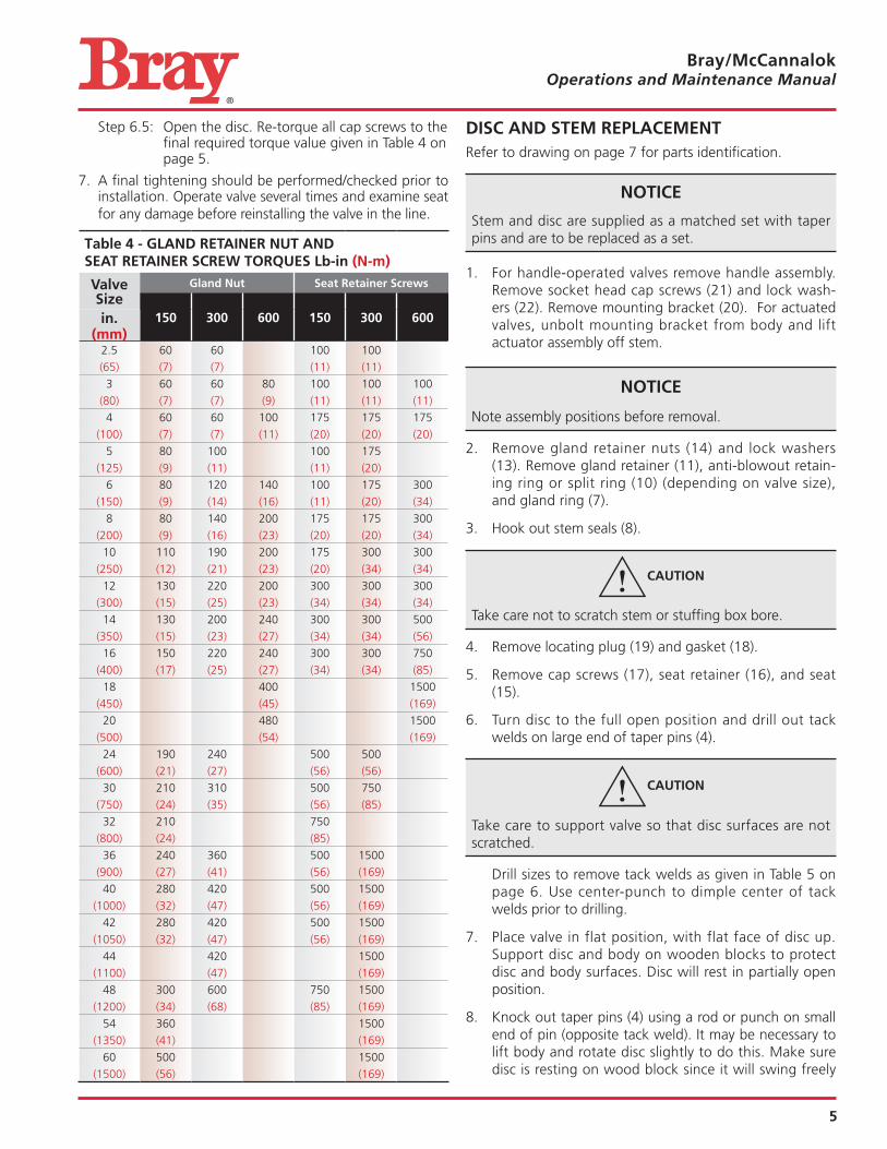
Step 6 5: Open the disc Re-torque all cap screws to the final required torque value given in Table 4 on page 5
7 A final tightening should be performed/checked prior to installation Operate valve several times and examine seat for any damage before reinstalling the valve in the line
Table 4 - GLAND RETAINER NUT AND SEAT RETAINER SCREW TORQUES Lb-in (N-m)
Valve Size
Gland Nut Seat Retainer Screws
150 300 600 150 300 600in.(mm)
2 5 60 60 100 100
(65) (7) (7) (11) (11)
3 60 60 80 100 100 100
(80) (7) (7) (9) (11) (11) (11)
4 60 60 100 175 175 175
(100) (7) (7) (11) (20) (20) (20)
5 80 100 100 175
(125) (9) (11) (11) (20)
6 80 120 140 100 175 300
(150) (9) (14) (16) (11) (20) (34)
8 80 140 200 175 175 300
(200) (9) (16) (23) (20) (20) (34)
10 110 190 200 175 300 300
(250) (12) (21) (23) (20) (34) (34)
12 130 220 200 300 300 300
(300) (15) (25) (23) (34) (34) (34)
14 130 200 240 300 300 500
(350) (15) (23) (27) (34) (34) (56)
16 150 220 240 300 300 750
(400) (17) (25) (27) (34) (34) (85)
18 400 1500
(450) (45) (169)
20 480 1500
(500) (54) (169)
24 190 240 500 500
(600) (21) (27) (56) (56)
30 210 310 500 750
(750) (24) (35) (56) (85)
32 210 750
(800) (24) (85)
36 240 360 500 1500
(900) (27) (41) (56) (169)
40 280 420 500 1500
(1000) (32) (47) (56) (169)
42 280 420 500 1500
(1050) (32) (47) (56) (169)
44 420 1500
(1100) (47) (169)
48 300 600 750 1500
(1200) (34) (68) (85) (169)
54 360 1500
(1350) (41) (169)
60 500 1500
(1500) (56) (169)
DISC AND STEM REPLACEMENTRefer to drawing on page 7 for parts identification
NOTICE
Stem and disc are supplied as a matched set with taper pins and are to be replaced as a set
1 For handle-operated valves remove handle assembly Remove socket head cap screws (21) and lock wash-ers (22) Remove mounting bracket (20) For actuated valves, unbolt mounting bracket from body and lift actuator assembly off stem
NOTICE
Note assembly positions before removal
2 Remove gland retainer nuts (14) and lock washers (13) Remove gland retainer (11), anti-blowout retain-ing ring or split ring (10) (depending on valve size), and gland ring (7)
3 Hook out stem seals (8)
Take care not to scratch stem or stuffing box bore
4 Remove locating plug (19) and gasket (18)
5 Remove cap screws (17), seat retainer (16), and seat (15)
6 Turn disc to the full open position and drill out tack welds on large end of taper pins (4)
Take care to support valve so that disc surfaces are not scratched
Drill sizes to remove tack welds as given in Table 5 on page 6 Use center-punch to dimple center of tack welds prior to drilling
7 Place valve in flat position, with flat face of disc up Support disc and body on wooden blocks to protect disc and body surfaces Disc will rest in partially open position
8 Knock out taper pins (4) using a rod or punch on small end of pin (opposite tack weld) It may be necessary to lift body and rotate disc slightly to do this Make sure disc is resting on wood block since it will swing freely
6
Bray/McCannalok Operations and Maintenance Manual
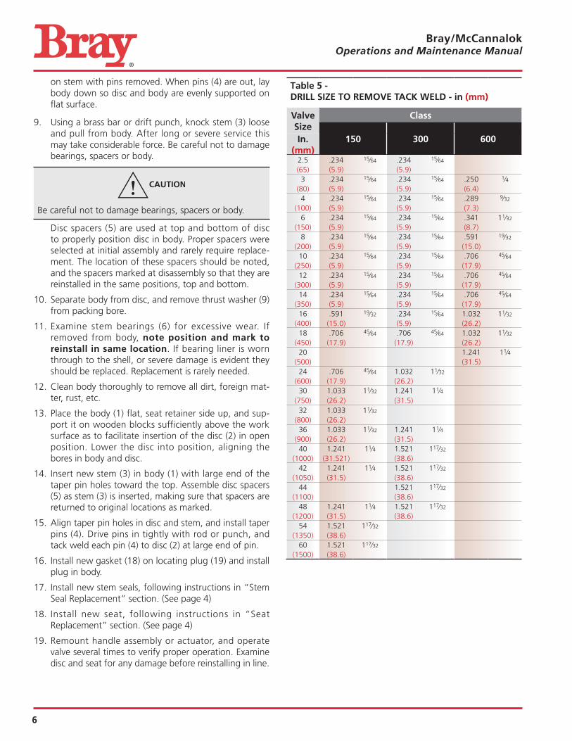
on stem with pins removed When pins (4) are out, lay body down so disc and body are evenly supported on flat surface
9 Using a brass bar or drift punch, knock stem (3) loose and pull from body After long or severe service this may take considerable force Be careful not to damage bearings, spacers or body
Be careful not to damage bearings, spacers or body
Disc spacers (5) are used at top and bottom of disc to properly position disc in body Proper spacers were selected at initial assembly and rarely require replace-ment The location of these spacers should be noted, and the spacers marked at disassembly so that they are reinstalled in the same positions, top and bottom
10 Separate body from disc, and remove thrust washer (9) from packing bore
11 Examine stem bearings (6) for excessive wear If removed from body, note position and mark to reinstall in same location If bearing liner is worn through to the shell, or severe damage is evident they should be replaced Replacement is rarely needed
12 Clean body thoroughly to remove all dirt, foreign mat-ter, rust, etc
13 Place the body (1) flat, seat retainer side up, and sup-port it on wooden blocks sufficiently above the work surface as to facilitate insertion of the disc (2) in open position Lower the disc into position, aligning the bores in body and disc
14 Insert new stem (3) in body (1) with large end of the taper pin holes toward the top Assemble disc spacers (5) as stem (3) is inserted, making sure that spacers are returned to original locations as marked
15 Align taper pin holes in disc and stem, and install taper pins (4) Drive pins in tightly with rod or punch, and tack weld each pin (4) to disc (2) at large end of pin
16 Install new gasket (18) on locating plug (19) and install plug in body
17 Install new stem seals, following instructions in “Stem Seal Replacement” section (See page 4)
18 Install new seat, following instructions in “Seat Replacement” section (See page 4)
19 Remount handle assembly or actuator, and operate valve several times to verify proper operation Examine disc and seat for any damage before reinstalling in line
Table 5 - DRILL SIZE TO REMOVE TACK WELD - in (mm)
Valve Size
Class
150 300 600In.(mm)
2 5 234 15⁄64 234 15⁄64
(65) (5 9) (5 9)3 234 15⁄64 234 15⁄64 250 1⁄4
(80) (5 9) (5 9) (6 4)4 234 15⁄64 234 15⁄64 289 9⁄32
(100) (5 9) (5 9) (7 3)6 234 15⁄64 234 15⁄64 341 11⁄32
(150) (5 9) (5 9) (8 7)8 234 15⁄64 234 15⁄64 591 19⁄32
(200) (5 9) (5 9) (15 0)10 234 15⁄64 234 15⁄64 706 45⁄64
(250) (5 9) (5 9) (17 9)12 234 15⁄64 234 15⁄64 706 45⁄64
(300) (5 9) (5 9) (17 9)14 234 15⁄64 234 15⁄64 706 45⁄64
(350) (5 9) (5 9) (17 9)16 591 19⁄32 234 15⁄64 1 032 11⁄32
(400) (15 0) (5 9) (26 2)18 706 45⁄64 706 45⁄64 1 032 11⁄32
(450) (17 9) (17 9) (26 2)20 1 241 11⁄4
(500) (31 5)24 706 45⁄64 1 032 11⁄32
(600) (17 9) (26 2)30 1 033 11⁄32 1 241 11⁄4
(750) (26 2) (31 5)32 1 033 11⁄32
(800) (26 2)36 1 033 11⁄32 1 241 11⁄4
(900) (26 2) (31 5)40 1 241 11⁄4 1 521 117⁄32
(1000) (31 521) (38 6)42 1 241 11⁄4 1 521 117⁄32
(1050) (31 5) (38 6)44 1 521 117⁄32
(1100) (38 6)48 1 241 11⁄4 1 521 117⁄32
(1200) (31 5) (38 6)54 1 521 117⁄32
(1350) (38 6)60 1 521 117⁄32
(1500) (38 6)
7
Bray/McCannalok Operations and Maintenance Manual
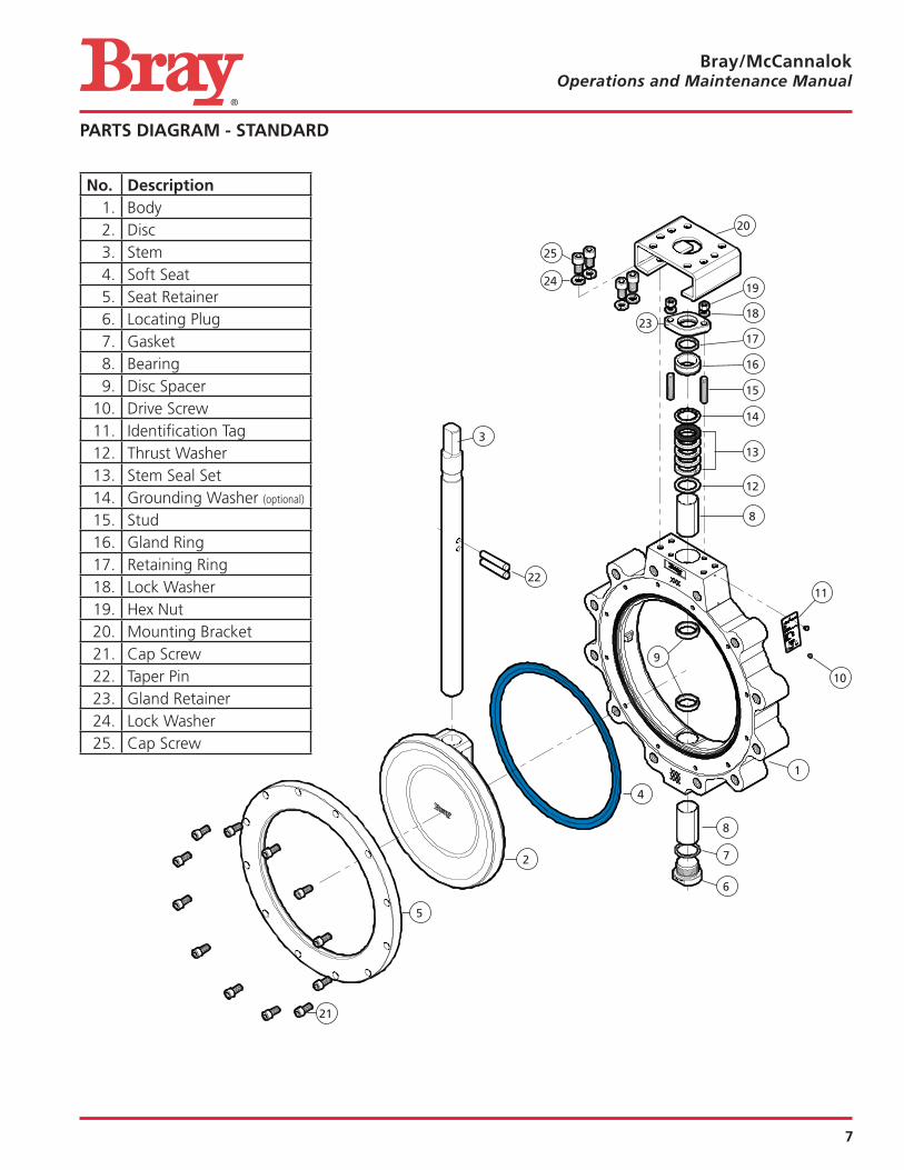
No. Description1 Body2 Disc3 Stem4 Soft Seat5 Seat Retainer6 Locating Plug7 Gasket8 Bearing9 Disc Spacer
10 Drive Screw11 Identification Tag12 Thrust Washer13 Stem Seal Set14 Grounding Washer (optional)
15 Stud16 Gland Ring17 Retaining Ring18 Lock Washer19 Hex Nut20 Mounting Bracket21 Cap Screw22 Taper Pin23 Gland Retainer24 Lock Washer25 Cap Screw
PARTS DIAGRAM - STANDARD
20
8
10
16
12
11
17
15
14
18
19
23
25
24
3
22
1
8
7
6
2
4
5
21
9
13
8
Bray/McCannalok Operations and Maintenance Manual
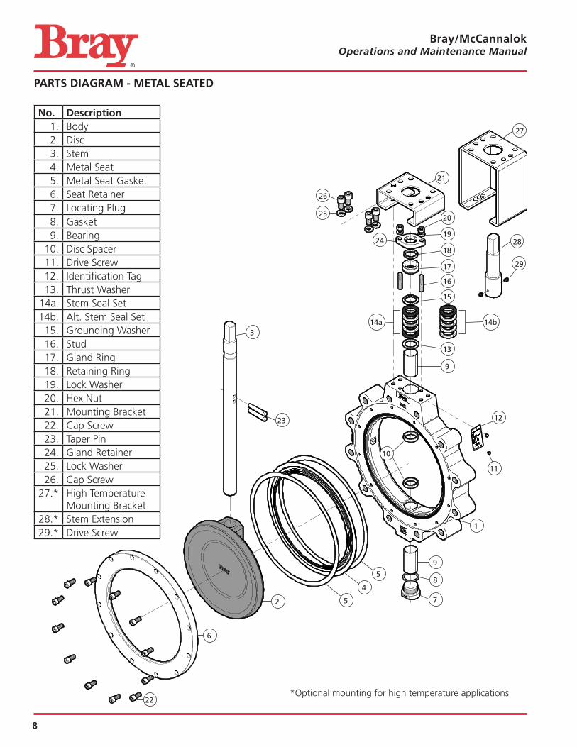
PARTS DIAGRAM - METAL SEATED
No. Description1 Body2 Disc3 Stem4 Metal Seat5 Metal Seat Gasket6 Seat Retainer7 Locating Plug8 Gasket9 Bearing
10 Disc Spacer11 Drive Screw12 Identification Tag13 Thrust Washer
14a Stem Seal Set14b Alt Stem Seal Set
15 Grounding Washer16 Stud17 Gland Ring18 Retaining Ring19 Lock Washer20 Hex Nut21 Mounting Bracket22 Cap Screw23 Taper Pin24 Gland Retainer25 Lock Washer26 Cap Screw
27 * High Temperature Mounting Bracket
28 * Stem Extension29 * Drive Screw
21
9
11
17
14b14a
13
12
18
16
15
19
20
24
26
27
25
3
23
1
9
8
72
4
6
22
10
28
29
*Optional mounting for high temperature applications
5
5
9
Bray/McCannalok Operations and Maintenance Manual
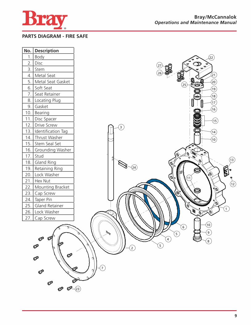
PARTS DIAGRAM - FIRE SAFE
No. Description1 Body2 Disc3 Stem4 Metal Seat5 Metal Seat Gasket6 Soft Seat7 Seat Retainer8 Locating Plug9 Gasket
10 Bearing11 Disc Spacer12 Drive Screw13 Identification Tag14 Thrust Washer15 Stem Seal Set16 Grounding Washer17 Stud18 Gland Ring19 Retaining Ring20 Lock Washer21 Hex Nut22 Mounting Bracket23 Cap Screw24 Taper Pin25 Gland Retainer26 Lock Washer27 Cap Screw
22
10
12
18
15
14
13
19
17
16
20
21
25
27
26
3
24
1
10
9
8
2
4
5
6
5
7
23
11
10
Bray/McCannalok Operations and Maintenance Manual
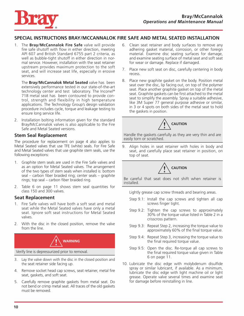
SPECIAL INSTRUCTIONS BRAY/MCCANNALOK FIRE SAFE AND METAL SEATED INSTALLATION 1 The Bray/McCannalok Fire Safe valve will provide
fire safe shutoff with flow in either direction, meeting API 607 and British Standard 6755 part 2 criteria, as well as bubble-tight shutoff in either direction in nor-mal service However, installation with the seat retainer upstream provides maximum protection to the soft seat, and will increase seat life, especially in erosive services
The Bray/McCannalok Metal Seated valve has been extensively performance tested in our state-of-the-art technology center and test laboratory The Inconel® 718 metal seat has been contoured to provide con-trol, strength and flexibility in high temperature applications The Technology Group’s design validation procedure includes cycle, torque and leakage testing to ensure long service life
2 Installation bolting information given for the standard Bray/McCannalok valves is also applicable to the Fire Safe and Metal Seated versions
Stem Seal ReplacementThe procedure for replacement on page 4 also applies to Metal Seated valves that use TFE (white) seals For Fire Safe and Metal Seated valves that use graphite stem seals, use the following exceptions:
1 Graphite stem seals are used in the Fire Safe valves and as an option for Metal Seated valves The arrangement of the two types of stem seals when installed is: bottom seal – carbon fiber braided ring; center seals – graphite rings; top seal – carbon fiber braided ring
2 Table 6 on page 11 shows stem seal quantities for class 150 and 300 valves
Seat Replacement1 Fire Safe valves will have both a soft seat and metal
seat while the Metal Seated valves have only a metal seat Ignore soft seat instructions for Metal Seated valves
2 With the disc in the closed position, remove the valve from the line
Verify line is depressurized prior to removal
3 Lay the valve down with the disc in the closed position and the seat retainer side facing up
4 Remove socket head cap screws, seat retainer, metal fire seat, gaskets, and soft seat
5 Carefully remove graphite gaskets from metal seat Do not bend or crimp metal seat All traces of the old gaskets must be removed
6 Clean seat retainer and body surfaces to remove any adhering gasket material, corrosion, or other foreign material Examine disc seating surfaces for damage, and examine seating surface of metal seat and soft seat for wear or damage Replace if damaged
7 Place new soft seat on disc, carefully centering in body recess
8 Place new graphite gasket on the body Position metal seat over the disc, lip facing out, on top of the polymer seat Place another graphite gasket on top of the metal seat Graphite gaskets can be first attached to the metal seat to simplify the assembly Spray a suitable adhesive, like 3M Super 77 general purpose adhesive or similar, in 3 or 4 spots on both sides of the metal seat to hold the gaskets in position
Handle the gaskets carefully as they are very thin and are easily torn or scratched
9 Align holes in seat retainer with holes in body and seat, and carefully place seat retainer in position, on top of seat
Be careful that seat does not shift when retainer is installed
Lightly grease cap screw threads and bearing areas
Step 9 1: Install the cap screws and tighten all cap screws finger tight
Step 9 2: Tighten the cap screws to approximately 30% of the torque value listed in Table 2 in a crisscross pattern
Step 9 3: Repeat Step 2, increasing the torque value to approximately 60% of the final torque value
Step 9 4: Repeat Step 3, increasing the torque value to the final required torque value
Step 9 5: Open the disc Re-torque all cap screws to the final required torque value given in Table 6 on page 11
10 Lubricate the disc edge with molybdenum disulfide spray or similar lubricant, if available As a minimum, lubricate the disc edge with light machine oil or light grease Operate valve several times and examine seat for damage before reinstalling in line
11
Bray/McCannalok Operations and Maintenance Manual
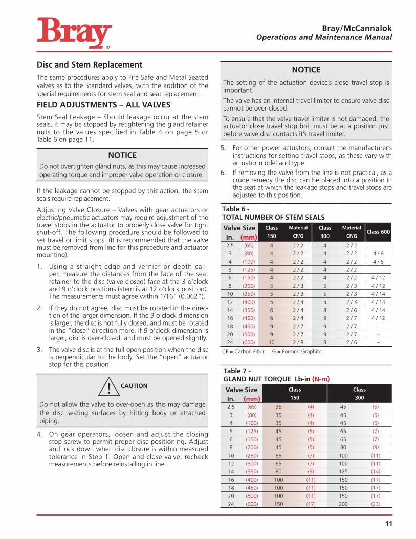
Disc and Stem Replacement
The same procedures apply to Fire Safe and Metal Seated valves as to the Standard valves, with the addition of the special requirements for stem seal and seat replacement
FIELD ADJUSTMENTS – ALL VALVESStem Seal Leakage – Should leakage occur at the stem seals, it may be stopped by retightening the gland retainer nuts to the values specified in Table 4 on page 5 or Table 6 on page 11
NOTICEDo not overtighten gland nuts, as this may cause increased operating torque and improper valve operation or closure
If the leakage cannot be stopped by this action, the stem seals require replacement
Adjusting Valve Closure – Valves with gear actuators or electric/pneumatic actuators may require adjustment of the travel stops in the actuator to properly close valve for tight shut-off The following procedure should be followed to set travel or limit stops (It is recommended that the valve must be removed from line for this procedure and actuator mounting)
1 Using a straight-edge and vernier or depth cali-per, measure the distances from the face of the seat retainer to the disc (valve closed) face at the 3 o’clock and 9 o’clock positions (stem is at 12 o’clock position) The measurements must agree within 1/16” (0 062”)
2 If they do not agree, disc must be rotated in the direc-tion of the larger dimension If the 3 o’clock dimension is larger, the disc is not fully closed, and must be rotated in the “close” direction more If 9 o’clock dimension is larger, disc is over-closed, and must be opened slightly
3 The valve disc is at the full open position when the disc is perpendicular to the body Set the “open” actuator stop for this position
Do not allow the valve to over-open as this may damage the disc seating surfaces by hitting body or attached piping
4 On gear operators, loosen and adjust the closing stop screw to permit proper disc positioning Adjust and lock down when disc closure is within measured tolerance in Step 1 Open and close valve; recheck measurements before reinstalling in line
NOTICE
The setting of the actuation device’s close travel stop is important
The valve has an internal travel limiter to ensure valve disc cannot be over closed
To ensure that the valve travel limiter is not damaged, the actuator close travel stop bolt must be at a position just before valve disc contacts it’s travel limiter
5 For other power actuators, consult the manufacturer’s instructions for setting travel stops, as these vary with actuator model and type
6 If removing the valve from the line is not practical, as a crude remedy the disc can be placed into a position in the seat at which the leakage stops and travel stops are adjusted to this position
Table 6 - TOTAL NUMBER OF STEM SEALS
Valve Size Class
150
Material
CF/G
Class
300
Material
CF/GClass 600
In. (mm)2 5 (65) 4 2 / 2 4 2 / 2 –
3 (80) 4 2 / 2 4 2 / 2 4 / 8
4 (100) 4 2 / 2 4 2 / 2 4 / 8
5 (125) 4 2 / 2 4 2 / 2 –
6 (150) 4 2 / 2 4 2 / 2 4 / 12
8 (200) 5 2 / 3 5 2 / 3 4 / 12
10 (250) 5 2 / 3 5 2 / 3 4 / 14
12 (300) 5 2 / 3 5 2 / 3 4 / 14
14 (350) 6 2 / 4 8 2 / 6 4 / 14
16 (400) 6 2 / 4 9 2 / 7 4 / 12
18 (450) 9 2 / 7 9 2 / 7 –
20 (500) 9 2 / 7 9 2 / 7 –
24 (600) 10 2 / 8 8 2 / 6 –
CF = Carbon Fiber G = Formed Graphite
Table 7 - GLAND NUT TORQUE Lb-in (N-m)
Valve Size Class
150
Class
300In. (mm)2 5 (65) 35 (4) 45 (5)
3 (80) 35 (4) 45 (5)
4 (100) 35 (4) 45 (5)
5 (125) 45 (5) 65 (7)
6 (150) 45 (5) 65 (7)
8 (200) 45 (5) 80 (9)
10 (250) 65 (7) 100 (11)
12 (300) 65 (7) 100 (11)
14 (350) 80 (9) 125 (14)
16 (400) 100 (11) 150 (17)
18 (450) 100 (11) 150 (17)
20 (500) 100 (11) 150 (17)
24 (600) 150 (17) 200 (23)

Bray/McCannalok Operations and Maintenance Manual
All statements, technical information, and recommendations in this bulletin are for general use only Consult Bray representatives or factory for the specific requirements and material selection for your intended application The right to change or modify product design or product without prior notice is reserved Patents issued and applied for worldwide
Bray® is a registered trademark ofBray International, Inc © 2015 Bray International, Inc All rights reserved
OM_Bray/McCannalok_06_01_2015
Bray ControlsDivision of Bray International, Inc 13333 Westland East Blvd Houston, Texas 77041Tel: 281 894 5454 • www bray com