Zxsdr bs8906 e product description(configured with b8100) 20100825
35
Product Type Technical Proposal ZTE Confidential Proprietary © 2008 ZTE Corporation.All rights reserved. I ZXSDR BS8906E Product Description
-
Upload
adeepcdma -
Category
Technology
-
view
320 -
download
5
Transcript of Zxsdr bs8906 e product description(configured with b8100) 20100825

Product Type Technical Proposal
ZTE Confidential Proprietary © 2008 ZTE Corporation.All rights reserved. I
ZXSDR BS8906E Product Description

ZXSDR BS8906E Product Description
ZTE Confidential Proprietary © 2008 ZTE Corporation.All rights reserved. I
ZXSDR BS8906E Product Description
Version Date Author Approved By Remarks
V1.0 2009-11-22 Li Chunying
Li Jian, Chang Zitong,
Xiao Rongjian,
Wang Xiaoming, Xu Falu
Not open to the third party
2009-12-07 Li Chunying Update the content description
2010-02-09 Xu Zihua
Li Chunying
Modify Standards Complied
2010-02-25 Li Chunying Modify the Module Layout, add 1.9 GHz, etc.
2010-07-09 Li Chunying Modify the power consumption, etc.
2010-08-24 Li Chunying Add the indices explanation of Power Consumption
© 2010 ZTE Corporation. All rights reserved.
ZTE CONFIDENTIAL: This document contains proprietary information of ZTE and is not to be disclosed or used without the prior written permission of ZTE.
Due to update and improvement of ZTE products and technologies, information in this document is subjected to change without notice.
ZXSDR BS8906E Product Description
ZTE Confidential Proprietary © 2008 ZTE Corporation.All rights reserved. II
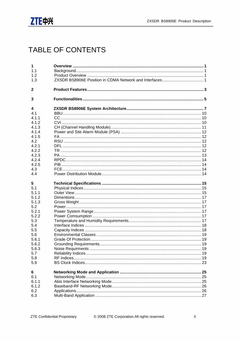
TABLE OF CONTENTS
1 Overview ..................................................................................................................... 1 1.1 Background .................................................................................................................. 1 1.2 Product Overview ........................................................................................................ 1 1.3 ZXSDR BS8906E Position in CDMA Network and Interfaces ..................................... 1
2 Product Features ........................................................................................................ 3
3 Functionalities ............................................................................................................ 5
4 ZXSDR BS8906E System Architecture..................................................................... 7 4.1 BBU ............................................................................................................................ 10 4.1.1 CC .............................................................................................................................. 10 4.1.2 CVI ............................................................................................................................. 10 4.1.3 CH (Channel Handling Module) ................................................................................. 11 4.1.4 Power and Site Alarm Module (PSA) ........................................................................ 12 4.1.5 FA .............................................................................................................................. 12 4.2 RSU ........................................................................................................................... 12 4.2.1 DFL ............................................................................................................................ 12 4.2.2 TR .............................................................................................................................. 12 4.2.3 PA .............................................................................................................................. 13 4.2.4 RPDC ......................................................................................................................... 14 4.2.5 PIB ............................................................................................................................. 14 4.3 FCE ............................................................................................................................ 14 4.4 Power Distribution Module ......................................................................................... 14
5 Technical Specifications ......................................................................................... 15 5.1 Physical Indices ......................................................................................................... 15 5.1.1 Outer View ................................................................................................................. 15 5.1.2 Dimentions ................................................................................................................. 17 5.1.3 Gross Weight ............................................................................................................. 17 5.2 Power ......................................................................................................................... 17 5.2.1 Power System Range ................................................................................................ 17 5.2.2 Power Comsumption ................................................................................................. 17 5.3 Temperature and Humidity Requirements ................................................................. 17 5.4 Interface Indices ........................................................................................................ 18 5.5 Capacity Indices ........................................................................................................ 18 5.6 Environmental Classes .............................................................................................. 19 5.6.1 Grade Of Protection ................................................................................................... 19 5.6.2 Grounding Requirements ........................................................................................... 19 5.6.3 Noise Requirments .................................................................................................... 19 5.7 Reliability Indices ....................................................................................................... 19 5.8 RF Indices .................................................................................................................. 19 5.9 BS Clock Indices ........................................................................................................ 23
6 Networking Mode and Application ......................................................................... 25 6.1 Networking Mode ....................................................................................................... 25 6.1.1 Abis Interface Networking Mode ................................................................................ 25 6.1.2 Baseband-RF Networking Mode................................................................................ 26 6.2 Applications................................................................................................................ 26 6.3 Multi-Band Application ............................................................................................... 27

ZXSDR BS8906E Product Description
ZTE Confidential Proprietary © 2008 ZTE Corporation.All rights reserved. III
7 Appendix A: Standards Complied .......................................................................... 28
8 Appendix B: Abbreviations ..................................................................................... 30

ZXSDR BS8906E Product Description
ZTE Confidential Proprietary © 2008 ZTE Corporation.All rights reserved. IV
FIGURES
Figure 1 ZXSDR BS8906E Position in CDMA Network ............................................................... 2
Figure 2 ZXSDR BS8906E Module Layout .................................................................................. 7
Figure 3 ZXSDR BS8906E Structure ........................................................................................... 8
Figure 4 ZXSDR BS8906E Baseband Cabinet Module Layout ................................................... 9
Figure 5 ZXSDR BS8906E RF Cabinet (RC8906) Module Layout ............................................ 10
Figure 6 ZXSDR BS8906E Outer View ...................................................................................... 15
Figure 7 ZXSDR BS8906E baseband cabinet (BC8906) Outer View ....................................... 16
Figure 8 ZXSDR BS8906E RF cabinet (RC8906) Outer View .................................................. 16
Figure 9 Abis Interface Networking Mode .................................................................................. 25
Figure 10 Baseband-RF Interface Networking ............................................................................. 26
TABLES
Table 1 Primary Functions of ZXSDR BS8906E ........................................................................ 5
Table 2 Normal Power Consumption with -48 V DC Power Supply ......................................... 17
Table 3 Temperature Requirements ......................................................................................... 18
Table 4 Interface Indices ........................................................................................................... 18
Table 5 Transmitter indices (Band Class 0 (800MHz)) ............................................................. 19
Table 6 Transmitter indices (1.9 GHz,2.1GHz)) ....................................................................... 21
Table 7 Receiver indices (Band Class 0 (800MHz)) ................................................................. 22
Table 8 Receiver indices (1.9 GHz,2.1GHz) ............................................................................. 23
Table 9 Abbreviations ............................................................................................................... 30
ZXSDR BS8906E Product Description
ZTE Confidential Proprietary © 2008 ZTE Corporation. All rights reserved. 1
1 Overview
1.1 Background
With growing competition in the telecommunication field, besides developing new services and attracting more subscribers, wireless operators also pay more attention on controlling effective Capital Expenditure (CAPEX) and Operation Expenditure (OPEX).
ZTE Software Defined Radio (SDR) uses an architecture of separating the baseband part from the Radio Frequency (RF) part. This architecture features high integration, low consumption, flexible configuration and convenient installation & maintenance. The new generation ZTE CDMA Base Station (BS) products based on the SDR is the first SDR-based CDMA BS in the industry. It is able to help the operators have qualitative leap. The form of this product can be distributed BBU plus RRU. The product form of ZTE SDR can be distributed BBU+RRU, macro BS or micro BS.
1.2 Product Overview
The ZXSDR BS8906E is an outdoor micro BS based on the SDR. It is used to modulate and demodulate baseband, transmit and demodulate RF signal, allocate radio resource, perform call processing, power control and soft handoff.
With All-IP design, the ZXSDR BS8906E is an outdoor micro BS in the distributed architecture. A single BS8906E can support 12 CS CDMA2000 1X + 1xEV-DO service, and support 3 sectors capacity. The ZXSDR BS8906E features small size, light weight, multi-band and convenient capacity expansion. It is suitable for outdoor applications with small capacity and low cost.
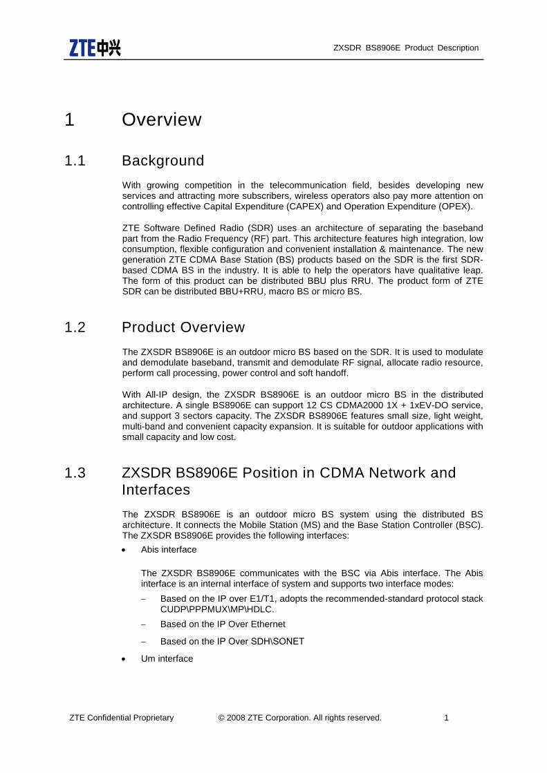
1.3 ZXSDR BS8906E Position in CDMA Network and Interfaces
The ZXSDR BS8906E is an outdoor micro BS system using the distributed BS architecture. It connects the Mobile Station (MS) and the Base Station Controller (BSC). The ZXSDR BS8906E provides the following interfaces:
Abis interface
The ZXSDR BS8906E communicates with the BSC via Abis interface. The Abis interface is an internal interface of system and supports two interface modes:
Based on the IP over E1/T1, adopts the recommended-standard protocol stack CUDP\PPPMUX\MP\HDLC.
Based on the IP Over Ethernet
Based on the IP Over SDH\SONET
Um interface

ZXSDR BS8906E Product Description
ZTE Confidential Proprietary © 2008 ZTE Corporation. All rights reserved. 2
Um interface is the interface between the Access Terminal (AT) and the BS. It conforms to the standards IS-2000 Release A and IS-856-A.
Baseband-RF interface
The ZXSDR BS8906E is connected to the RF System Unit (RSU) or the Remote RF Unit (RRU). It supports cascading and networking functions defined in the CPRI protocol.
ZXSDR
Core
Network
BSC
MS
MS
MS
BSC
M
S
M
S
M
SRRU
RRU
MSC
AGW
/PDSN
BSC
Um
air interface
Baseband-RF
interface
CPRI
Abis interface
(recommended-
standard)
A3/A7
interfaceA interface
(A1/A2/A5)
(A10/A11)
MSCMSC
MGW
PCF
BSC
PCF
A8/A9
interface
BBU
BS8906E
R
S
U
R
S
U
Figure 1 ZXSDR BS8906E Position in CDMA Network

ZXSDR BS8906E Product Description
ZTE Confidential Proprietary © 2008 ZTE Corporation. All rights reserved. 3
2 Product Features
By taking full consideration of operators’demands, the ZXSDR BS8906E offers the following unparalleled advantages:
A single ZXSDR BS8906E can support CDMA2000 1X and EV-DO services
simultaneously, which is suitable for application scenarios such as suburban and
rural areas, highways and blind zones.
The ZXSDR BS8906E is the most cost-effective multi-carrier outdoor micro base
station, which can help you to reduce the network construction cost.
The ZXSDR BS8906E is the smallest CDMA outdoor micro base station providing
3C4S configuration in the industry. It is easy for transport and installation, ensuring
fast deployment.
The ZXSDR BS8906E can be installed on a roof, wall, tower and pole, facilitating
site acquisition and simplifying site construction.
The ZXSDR BS8906E belongs to a family of green base stations. It can help you
improve the social image of your company while saving the electricity expense.
By using flexible Abis interface, the ZXSDR BS8906E supports transmission
solutions such as TDM, IP or hybrid networking of TDM and IP.
With the best transmission efficiency in the industry, the ZXSDR BS8906E can
significantly reduce the transmission bandwidth and cost per user, improving your
network value in fierce competition.
Front maintenance and bottom leading-out mode. All fans and lightning modules
can be removed on site.
Generic BS platform
The BBU adopts a platform based on the future-proof B3G or 4G design. Therefore, different standard systems can exist in one hardware platform or in one BS. This platform can help operators simplify operation management and combine many BSs that are required to be invested into one multi-mode BS. Besides, the platform helps the operators flexibly select the evolution trend of the future network and allow the terminal users experience network transparency and smooth evolution as well.
The smooth evolution to LTE
To support the smooth evolution to LTE, base-band part support LTE through pluging LTE baseband board.
Adopts the advanced Micro Telecom Computing Architecture (uTCA)

ZXSDR BS8906E Product Description
ZTE Confidential Proprietary © 2008 ZTE Corporation. All rights reserved. 4
The uTCA adopts the standard template, compact design and block architecture, which makes the operation more effective and of higher performance-price ratio.
The power-on management mode of uTCA is more reliable.
ZTE is the first vendor to develop a BS based on the uTCA architecture and takes the lead of the advanced technology in the telecommunication industry.

ZXSDR BS8906E Product Description
ZTE Confidential Proprietary © 2008 ZTE Corporation. All rights reserved. 5
3 Functionalities
The primary functions of the ZXSDR BS8906E are listed in the following Table 1.
Table 1 Primary Functions of ZXSDR BS8906E
Function Category Function Description
Basic Baseband Function
Modulation/demodulation
Radio resource management
Call processing
Handoff control
Power control
GPS timing and synchronization
Basic RF Function Band: 800MHz, 1.9 GHz,2.1GHz
RF modulation/demodulation
RF transceiver duplexer
Low noise amplification for received RF signal
Amplification for transmitted RF signal
RF transceiver
Interface The baseband-RF interface supports Common Public Radio Interface (CPRI) protocol.
The Abis interface supports IP Over Ethernet access.
The Abis interface supports IP Over E1/T1 access.
The Abis interface supports IP Over SDH\SONET access.
The air interface supports IS-2000 Release A and IS-856-A standards.
The Antenna Interface Standards Group (AISG) interface supports electrically adjustable antenna standards.
Networking Support for the remote application of RRU; networking modes including star and chain.
Support for the cascading networking mode of RRU, the highest up to 6 levels.
The Abis interface supports cascading of the daisy chains by IP Over E1/T1.
Environment Monitoring
Input power: undervoltage/overvoltage alarm
Output power: undervoltage/overvoltage alarm
Power: overcurrent alarm
Environment temperature alarm
External RS232/RS485 monitoring interfaces
External dry contacts monitoring interfaces
Equipment Support of front-maintenance

ZXSDR BS8906E Product Description
ZTE Confidential Proprietary © 2008 ZTE Corporation. All rights reserved. 6
Function Category Function Description
Maintenance Remote upgrade of software version for FPGA/BOOT/DSP/CPU
Remote reset and power off of service boards
Electronic label
Power query: baseband power, RF power and antenna output power
Automatic calibration
RSSI query
Reverse spectrum query: querying the reverse received signal spectrum of each carrier
Monitoring alarm for antenna standing wave ratio
Power amplification control and protection: over-power, over-temperature and standing wave alarm
Reliability Reverse voltage protection
Scenario Indoor and outdoor applications, for example, rural areas and towns. It is mainly used for outdoor and indoor applications as well as edge networks.

ZXSDR BS8906E Product Description
ZTE Confidential Proprietary © 2008 ZTE Corporation. All rights reserved. 7
4 ZXSDR BS8906E System Architecture
Based on the SDR architecture, the ZXSDR BS8906E has powerful competitiveness. Figure 2 shows the ZXSDR BS8906E module layout.
LPU/PDM/FAN
RS
U
RS
U
LP
U\S
DH
\mic
row
ave
IDU
FCE/FAN
DP
M/P
SU
PS
AC
HV
/CH
D
CH
V/C
HD
CC
CV
IFA
AP
M
Figure 2 ZXSDR BS8906E Module Layout
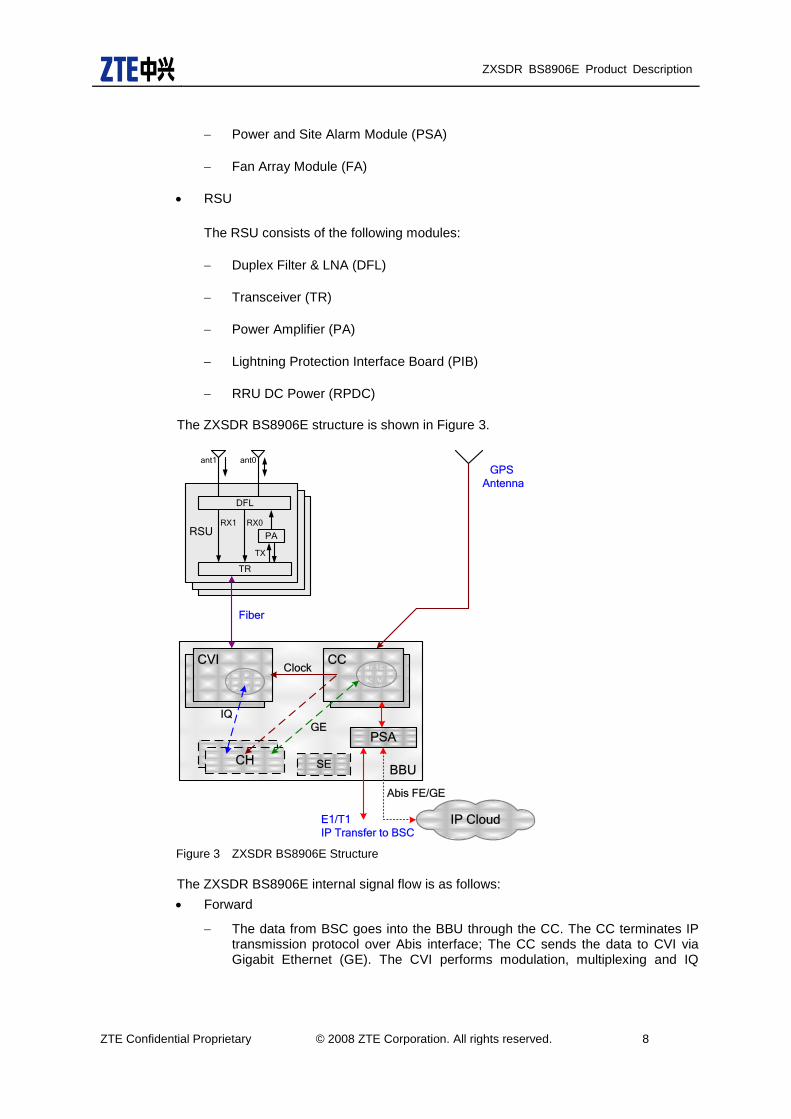
The ZXSDR BS8906E consists of BBU, RSU, FCE, PSU, APM\DPM, LPU\SDH\microwave IDU and so on. The internal communication takes place between BBU, RSU and FCE. The BBU and the RSU are connected to each other through the CPRI interface. The FCE is responsible for driving controlling and monitoring fans, controlling the on-off status of the heaters. Besides, the FCE collects and gives alarms for access control, temperature, flooding and lightning alarms. The FCE is connected to the PSA of the BBU through the RS485 interface to monitor communication inside the baseband, and the FCE is connected to the RSU through the RS485 interface to monitor communication inside the RF.
BBU
The BBU consists of the following modules:
Control and Clock Module (CC)
Channel Processing Voice & RF Interface Module (CVI)
Channel Handling Module (CH)
ZXSDR BS8906E Product Description
ZTE Confidential Proprietary © 2008 ZTE Corporation. All rights reserved. 8
Power and Site Alarm Module (PSA)
Fan Array Module (FA)
RSU
The RSU consists of the following modules:
Duplex Filter & LNA (DFL)
Transceiver (TR)
Power Amplifier (PA)
Lightning Protection Interface Board (PIB)
RRU DC Power (RPDC)
The ZXSDR BS8906E structure is shown in Figure 3.
CRUCRU
BBU
GPS
Antenna
ECCM
PSA
E1/T1
IP Transfer to BSCIP Cloud
Fiber
Abis FE/GE
Clock
CH
CCGE
SW
CVIIQ
SW
SE
IQ
GE
RSU PA
TR
TX
RX0
DFL
ant1 ant0
RX1
Figure 3 ZXSDR BS8906E Structure
The ZXSDR BS8906E internal signal flow is as follows:
Forward
The data from BSC goes into the BBU through the CC. The CC terminates IP transmission protocol over Abis interface; The CC sends the data to CVI via Gigabit Ethernet (GE). The CVI performs modulation, multiplexing and IQ

ZXSDR BS8906E Product Description
ZTE Confidential Proprietary © 2008 ZTE Corporation. All rights reserved. 9
switching of the data. After de-multiplexing, frame generation, parallel-to-serial conversion, the data is finally distributed to RSU via CPRI interface.
The TR receives the data after baseband modulation via the CPRI interface, performs up conversion of the data, and then sends the data to the PA. The PA amplifies the power of the input signal from the TR and then sends it to the DFL. The DFL processes the RF signal and then sends it via the antenna.
Reverse
The reverse CDMA signal from the antenna is sent to the TR after through the DFL. Then the CDMA signal is converted to a baseband digital signal by the TR and sent to the baseband via the CPRI interface.
After receiving the baseband signal from the RSU, the IQ SW of the CVI demultiplexes and demodulates the signal to get a service packet. Then the CVI converts the service packet to Ethernet frames and send the frames to the CC via GE. Then the CC processes the transmission protocol of Abis interface over IP and sends it to the BSC through E1/T1 or Ethernet. The BS8906E also supports IP Ethernet access mode.
The BS8906E baseband cabinet (BC8906) can be separately configured as an outdoor BBU. In this case, the RF cabinet and the RSU are not required.
LP
U\S
DH
\mic
row
ave
IDU
FCE/FAN
DP
M/P
SU
PS
AC
HV
/CH
D
CH
V/C
HD
CC
CV
IFA
AP
M
Figure 4 ZXSDR BS8906E Baseband Cabinet Module Layout
The BS8906E RF cabinet (RC8906) can be separately configured. In this case, the Baseband cabinet are not required.

ZXSDR BS8906E Product Description
ZTE Confidential Proprietary © 2008 ZTE Corporation. All rights reserved. 10
LPU/PDM/FAN
RS
U
RS
U
Figure 5 ZXSDR BS8906E RF Cabinet (RC8906) Module Layout
4.1 BBU
4.1.1 CC
The Control and Clock Module (CC) has the following functions:
GPS timing
Receiving GPS signal and providing system clock and RF reference clock.
Distributing system clock signal.
GE Ethernet switching
Providing switching platform for signaling and media stream respectively.
External interfaces
Abis interface: one Ethernet port (optical or RJ45 port)
One local operation and maintenance port - FE port.
4.1.2 CVI
The Channel Processing Voice & RF Interface Module (CVI) implements the following functions:
Remote baseband-RF CPRI interface
Support four remote baseband-RF CPRI interfaces
ZXSDR BS8906E Product Description
ZTE Confidential Proprietary © 2008 ZTE Corporation. All rights reserved. 11
Forward: the CVI multiplexes and frames the baseband data and then connects to the RRU through an optical interface.
Reverse: The CVI performs deframing and demultiplexing of the data from the RRU and then sends it to the BBU.
IQ switching
The CVI supports IQ switching with other channel boards in other AMC slots to implement channel sharing.
1X channel processing
Implement a variety of key technologies: diversity, RAKE receiver, softer handoff and power control.
Implement forward modulation and reverse demodulation of baseband signal.
Forward modulation and reverse demodulation support the following physical channels:
Forward: Pilot Channel, Sync Channel, Paging Channel, Quick Paging channel, Dedicated Control Channel, Forward Foundmental Channel, Forward Supplemental Channel and Forward Supplemental Code Channel
Reverse: Reverse Pilot Channel, Access Channel, Reverse Foundmental Channel, Reverse Supplemental Channel and Reverse Dedicated Control Channel.
4.1.3 CH (Channel Handling Module)
The CH mainly implements baseband forward modulation and reverse demodulation, and key technologies of CDMA like diversity technology, RAKE receiver, softer handoff and power control.
The CH includes CHV and CHD. CHV supports CDMA2000 1X and CHD supports 1x EV-DO.
The ZXSDR BS8906 system supports interchangeable installation of CHD and CHV to implement both 1x and EV-DO services.
The CH module performs forward modulation and reverse demodulation of baseband
and supports the following physical channels:
Forward: pilot channel, synchrnization channel, paging channel, quick paging
channel, forward dedicated control channel, forward fundmental channel, forward
supplemental channel and forward supplemental code channel
Reverse: reverse pilot channel, access channel, reverse fundmental channel,
reverse supplemental channel and reverse dedicated control channel

ZXSDR BS8906E Product Description
ZTE Confidential Proprietary © 2008 ZTE Corporation. All rights reserved. 12
4.1.4 Power and Site Alarm Module (PSA)
Power and Site alarm module (PSA) has the following functions:
Voltage conversion, processing and distribution for the inputted -48V DC power
source
Control and alarm for the fans.
Monitoring interfaces
External RS485/RS232 environment monitoring ports.
Dry contacts: 8 inputs.
Abis interface: up to 8-16 E1s/T1s
4.1.5 FA
The Fan Array Module (FA) provides speed control for the fans and temperature detection for the air inlet.
4.2 RSU
The RSU60 (1T2R) or RSU82 (2T4R) can be used as the RF functional entity.
As the first double-density module in CDMA field, RSU82 can be mounted in such system models as BS8906E, BS8800, and BS8900. It can be applied in double-sector 1T2R, single-sector high carrier, high power and dual band, etc. Its hardware supports LTE, and software upgrade can achieve CDMA/LTE mixed mode.
4.2.1 DFL
The Duplex Filter & LNA (DFL) has the following functions:
Performs filtering and low noise amplification of the reverse CDMA signal from the
antenna.
Filters the forward RF signal to be sent.
Reports LNA alarms to the TR.
In the case of main/diversity combined cabinets, the main receive LNA output end
of the DFL has the power splitter function and reserves an external port (Rx out).
4.2.2 TR
The Transceiver (TR) is the main control module of the RSU. It performs communication, control, and alarm and version management for the RSU.
The TR has the following functions of:
Forward link processing
Conversion from baseband signal to RF signal
Conversion of output IQ data format
Power calibration and detection processing

ZXSDR BS8906E Product Description
ZTE Confidential Proprietary © 2008 ZTE Corporation. All rights reserved. 13
Peak clipping/digital pre-distortion processing
Digital IF processing
Gain adjustment (calibration)
Reverse link processing
Conversion from RF signal to baseband signal
Digital IF processing
RSSI and RAB report
In-band anti-interference function
Spectrum report
Automatic Gain Control (AGC)
Output IQ data format conversion
Supports switching between different receive channel signals in the case of main/diversity combined cabinets.
Clock processing function
Performs clock recovery for data on the CPRI between the RSU and the BBU generating a reference clock source. Performs phase lock for the reference clock by utilizing a local high-stability clock. The working clocks generated include the master clock, frame- frequency clock, digital processing clock and RF baseband clock.
Monitoring function
PA forward power detection function: when the temperature threshold is exceeded, the TR reports the relevant alarm and controls the PA through the PA output enable/disable signal.
PA reversed power (standing wave ratio) detection function: when the temperature threshold standing of the standing wave ratio is exceeded, the TR reports the relevant alarm and controls the PA through the PA output enable/disable signal.
PA temperature detection function: When the temperature threshold is exceeded, the TR reports the relevant alarm and controls the PA through the PA output enable/disable signal.
PA output enable/disable
TR transmit output power detection
DFL two-channel LNA alarm detection and report
RPDC input undervoltage/overvoltage alarm detection and report
RPDC output undervoltage/overvoltage alarm detection and report
RPDC output overcurrent alarm detection and report
System environment monitoring
CPRI self-test alarm
Key chip self-test alarm
4.2.3 PA
The Power Amplifier (PA) has the following functions:
Amplifies downlink RF signal input via the TR and then sends the signal to the DFL.

ZXSDR BS8906E Product Description
ZTE Confidential Proprietary © 2008 ZTE Corporation. All rights reserved. 14
Provides digital pre-distortion feedback signals for the TR.
Provides a PA output enable/disable interface.
4.2.4 RPDC
The RRU DC Power Supply (RPDC) converts –48 V DC input power supply to DC power supply required by the PA, TR, or DFL.
4.2.5 PIB
The Lightning Protection Interface Board (PIB) performs the functions of AISG interface, RS485 extension interface, panel transfer of the dry contacts and lightning protection. Besides, the PIB transfers the signal from the debugging FE interface and the indicators and the board reset signal as well on the TR to the front panel.
4.3 FCE
The FCE detects the external and internal environment temperature in real time. It is used to implement power supply allocation, speed adjustment, status monitoring, control on the on-off status of the heaters. Besides, the FCE is responsible for collecting and giving alarms for cabinet access control, PIB status and PSU.
4.4 Power Distribution Module
The DPM or APM & PSU can be configured to support -48 V DC and 110/220 V AC respectively so as to implement lightning protection, filtering, AC-to-DC conversion, allocation and grounding for working power.

ZXSDR BS8906E Product Description
ZTE Confidential Proprietary © 2008 ZTE Corporation. All rights reserved. 15
5 Technical Specifications
5.1 Physical Indices
5.1.1 Outer View
The ZXSDR BS8906E outer view is shown in Figure 6.
Figure 6 ZXSDR BS8906E Outer View

ZXSDR BS8906E Product Description
ZTE Confidential Proprietary © 2008 ZTE Corporation. All rights reserved. 16
Figure 7 ZXSDR BS8906E baseband cabinet (BC8906) Outer View
Figure 8 ZXSDR BS8906E RF cabinet (RC8906) Outer View
ZXSDR BS8906E Product Description
ZTE Confidential Proprietary © 2008 ZTE Corporation. All rights reserved. 17
5.1.2 Dimentions
Dimensions of BS8906E single cabinet (H*W*D): 600 × 420 × 480 (mm)
Dimensions of BS8906E baseband cabinet (H*W*D): 600 × 210 × 480 (mm)
Dimensions of BS8906E RF cabinet (H*W*D): 600 × 210 × 480 (mm)
5.1.3 Gross Weight
The weight of the whole system with full configuration is less than or equal 70 kg.
The weight of RC8906:<=40 kg.
The weight of BC8906:<=30 kg.
5.2 Power
5.2.1 Power System Range
Power supply modes:
DC: -48 V; voltage fluctuation range: -18 V to -62 V
AC: 220 V; voltage fluctuation range: 150-300 V
AC: 110 V; voltage fluctuation range: 85-135 V
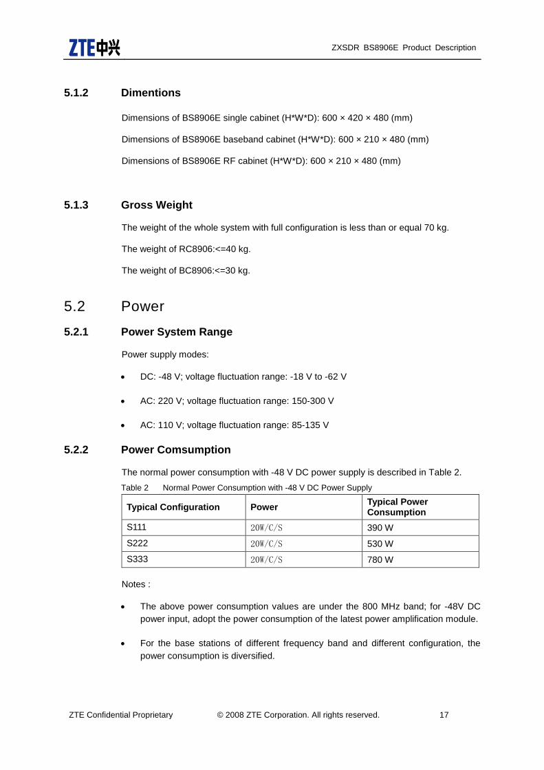
5.2.2 Power Comsumption
The normal power consumption with -48 V DC power supply is described in Table 2.
Table 2 Normal Power Consumption with -48 V DC Power Supply
Typical Configuration Power Typical Power Consumption
S111 20W/C/S 390 W
S222 20W/C/S 530 W
S333 20W/C/S 780 W
Notes :
The above power consumption values are under the 800 MHz band; for -48V DC
power input, adopt the power consumption of the latest power amplification module.
For the base stations of different frequency band and different configuration, the
power consumption is diversified.

ZXSDR BS8906E Product Description
ZTE Confidential Proprietary © 2008 ZTE Corporation. All rights reserved. 18
5.3 Temperature and Humidity Requirements Table 3 Temperature Requirements
Item Requirement
Operating temperature -40C to +55C
Operating humidity 5%RH to 95%RH
5.4 Interface Indices
The interface indices are listed in Table 4.
Table 4 Interface Indices
Item Description Indices
Abis Interface E1/T1 8-16
Number of Ethernet interface
1 port (optical or RJ45 port)
E1/T1 daisy chain levels 4
Baseband-RF interface Interface protocol between BBU and RRU
CPRI
Medium for BBU and RRU interface
Optical port/high-speed cable interface
Number of baseband-RF interfaces supported by the BBU
4 (One interface is connected with the RSU inside the cabinet.)
Cascading levels of RRU supported by one fiber
6
Length of a single link supported by RRU
< 80 km
Environment Monitoring Interface
Dry contact RC8906 supports 4 dry contacts: 4 inputs;
BC8906 supports 8 dry contacts: 8 inputs or 6 inputs & 2 outputs.
Serial port RC8906 supports one RS485.
BC8906 supports one RS232.
5.5 Capacity Indices
A single BS8906E can support 4C3S, 26.38 Erl per sector/carrier

ZXSDR BS8906E Product Description
ZTE Confidential Proprietary © 2008 ZTE Corporation. All rights reserved. 19
5.6 Environmental Classes
5.6.1 Grade Of Protection
IP55
5.6.2 Grounding Requirements
Joint grounding resistance 1; BTS grounding resistance 5 .
5.6.3 Noise Requirments
BTS working environmental noise: < 65 dBA.
5.7 Reliability Indices
Mean Time Between Failures (MTBF) >100,000 hours
MTTR (Mean Time To Repair) < 0.5 hour
Availability: > 99.999%
5.8 RF Indices
RF indices of the ZXSDR BS8906E comply with 3GPP2 C.S0010-C, Recommended Minimum Performance Standards for cdma2000 Spread Spectrum Base Station and 3GPP2 C.S0032-A, Recommended Minimum Performance Standards for CDMA2000 High Rate Packet Data Access Network.
Transmitter indices (Band Class 0 (800MHz))
Table 5 Transmitter indices (Band Class 0 (800MHz))
Name Index
Operating band 800MHz (Band Class 0)
Transmitter output frequency tolerance
±0.05 ppm
Occupied channel bandwidth
1.23 MHz (Band Class 0)
Output power at the Top of Cabinet (TOC)
60W/80W
Total transmit power The total transmit power is within +2 dB and -4 dB of the manufacturer’s rated power.
Modulation mode Quadrature amplitude modulation

ZXSDR BS8906E Product Description
ZTE Confidential Proprietary © 2008 ZTE Corporation. All rights reserved. 20
Name Index
Conducted spurious emission and radiated spurious emission suppression
-45 dBc @750 kHz offset Center Freq
(RBW 30 kHz)
-60 dBc @1.98 MHz offset Center Freq (RBW
30 kHz)
> 4 MHz OFFSET:
-36 dBm (RBW 1 kHz) @ 9 kHz < f <150 kHz
< -36 dBm (RBW 10 kHz) @ 150 kHz < f < 30 MHz
<-30 dBm (RBW 1 MHz) @ 1 GHz < f < 12.5 GHz
4-6.4 MHz OFFSET:
< -36 dBm (RBW 1 kHz) @ 30 MHz < f < 1 GHz
6.4M TO 16M OFFSET:
< -36 dBm (RBW 10 kHz) @ 30 MHz < f < 1GHz
> 16 MHz OFFSET:
< -36 dBm (RBW 100 kHz) @ 30 MHz < f < 1 GHz
Transmitter intermodulation performance
If one BTS transmits at the rated power but another BTS’ output power is 30 dB less than the former’s rated power. When the powers of two BTSs are combined on the antenna port, the generated intermodulation spurious emission meets the conducted spurious emission requirement. The IF difference of the transmit signals of two BTSs is 1.25M.
Pilot time tolerance The PN time tolerance falls within 3 us and the inter-carrier tolerance falls within 1 us.
Time Tolerance/phase tolerance of pilot channel to other channels
Time difference: < 50 ns
Phase difference: < 0.05 rad
Waveform quality Rho is greater than 0.970 dBm with configuration of a single pilot.
Pilot code domain power With the standard 9CH configuration, the pilot code domain power is in the range of -7.0±0.5 dB.
Inactive channel code domain power
With the standard 9CH configuration, the inactive channel code domain power is less than -27 dB.
DO MAC inactive channel code domain power
With configuration of 13 FLUSs, the MAC inactive channel code domain power is less than -29.5 dB (type 2).
DO DATA channel code domain power
With configuration of 13 FLUSs at the rate of 614.44 kbs (test 1), the DATA channel code domain power is in the range of -15.5 dB to -14.5 dB.
Wave quality of DO channels
Pilot channel: Rho > 0.97
MAC channel: Rho > 0.912
DATA channel: Rho > 0.97
Standing wave ratio of the RFE
1.50
Transmitter indices (1.9 GHz,2.1GHz)
ZXSDR BS8906E Product Description
ZTE Confidential Proprietary © 2008 ZTE Corporation. All rights reserved. 21
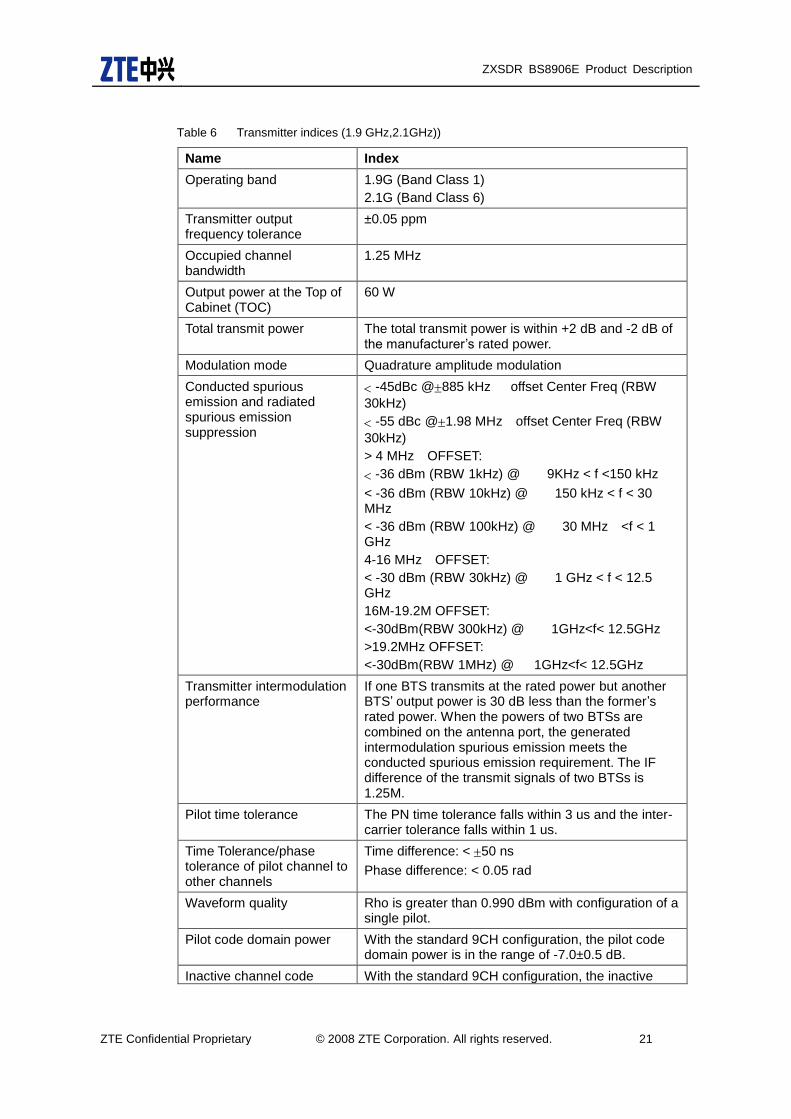
Table 6 Transmitter indices (1.9 GHz,2.1GHz))
Name Index
Operating band 1.9G (Band Class 1)
2.1G (Band Class 6)
Transmitter output frequency tolerance
±0.05 ppm
Occupied channel bandwidth
1.25 MHz
Output power at the Top of Cabinet (TOC)
60 W
Total transmit power The total transmit power is within +2 dB and -2 dB of the manufacturer’s rated power.
Modulation mode Quadrature amplitude modulation
Conducted spurious emission and radiated spurious emission suppression
-45dBc @885 kHz offset Center Freq (RBW
30kHz)
-55 dBc @1.98 MHz offset Center Freq (RBW
30kHz)
> 4 MHz OFFSET:
-36 dBm (RBW 1kHz) @ 9KHz < f <150 kHz
< -36 dBm (RBW 10kHz) @ 150 kHz < f < 30 MHz
< -36 dBm (RBW 100kHz) @ 30 MHz <f < 1 GHz
4-16 MHz OFFSET:
< -30 dBm (RBW 30kHz) @ 1 GHz < f < 12.5 GHz
16M-19.2M OFFSET:
<-30dBm(RBW 300kHz) @ 1GHz<f< 12.5GHz
>19.2MHz OFFSET:
<-30dBm(RBW 1MHz) @ 1GHz<f< 12.5GHz
Transmitter intermodulation performance
If one BTS transmits at the rated power but another BTS’ output power is 30 dB less than the former’s rated power. When the powers of two BTSs are combined on the antenna port, the generated intermodulation spurious emission meets the conducted spurious emission requirement. The IF difference of the transmit signals of two BTSs is 1.25M.
Pilot time tolerance The PN time tolerance falls within 3 us and the inter-carrier tolerance falls within 1 us.
Time Tolerance/phase tolerance of pilot channel to other channels
Time difference: < 50 ns
Phase difference: < 0.05 rad
Waveform quality Rho is greater than 0.990 dBm with configuration of a single pilot.
Pilot code domain power With the standard 9CH configuration, the pilot code domain power is in the range of -7.0±0.5 dB.
Inactive channel code With the standard 9CH configuration, the inactive

ZXSDR BS8906E Product Description
ZTE Confidential Proprietary © 2008 ZTE Corporation. All rights reserved. 22
Name Index
domain power channel code domain power is less than -27 dB.
DO MAC inactive channel code domain power
With configuration of 13 FLUSs, the MAC inactive channel code domain power is less than -29.5 dB (type 2).
DO DATA channel code domain power
With configuration of 13 FLUSs at the rate of 614.44 kbs (test 1), the DATA channel code domain power is in the range of -15.5 dB to -14.5 dB.
Wave quality of DO channels
Pilot channel: Rho > 0.97
MAC channel: Rho > 0.912
DATA channel: Rho > 0.97
Standing wave ratio of the RFE
1.50
Receiver indices (Band Class 0 (800MHz))
Table 7 Receiver indices (Band Class 0 (800MHz))
Name Index
Operating band 800 MHz (Band Class 0)
Receiver sensitivity < -130 dBm
Receiver dynamic range When the lower limit is the receiver sensitivity and the upper limit (noise level) equals -65dBm/1.23MHz (Eb/N0 = 10dB1dB), the Frame Error Rate (FER) is
lower than 1%.
Noise figure < 3
Single tone desensitization In the presence of a single tone that is 50 dB above the CDMA signal level, and is at offset of 750 kHz
from the center frequency, the output power of the MS increases by no more than 3 dB ,and the FER is less than 1.5%.
In the presence of a single tone that is 87 dB above the CDMA signal level, and is at offset of 900 kHz
from the center frequency, the output power of the MS increases by no more than 3 dB, and the FER is less than 1.5%.
Intermodulation spurious response attenuation
BAND 0:
In the presence of two interfering tones that are 72 dB above the CDMA signal level, and are at offsets of +900 kHz and +1.7 MHz, and -900 kHz and -1.7 MHz from the center frequency, the output power of the MS increases by no more than 3 dB, and the FER is less than 1.5%.
Conducted spurious emissions and radiated spurious emissions
< -80 dBm, measured within the BTS receive band
< -60 dBm, measured within the base station transmit band
Standing wave ratio of the RFE
1.50

ZXSDR BS8906E Product Description
ZTE Confidential Proprietary © 2008 ZTE Corporation. All rights reserved. 23
Receiver indices (Band Class 1 (1.9MHz))
Table 8 Receiver indices (1.9 GHz,2.1GHz)
Name Index
Operating band 1.9G (Band Class 1)
2.1G (Band Class 6)
Receiver sensitivity < -130 dBm
Receiver dynamic range When the lower limit is the receiver sensitivity and the upper limit (noise level) equals -65dBm/1.23MHz (Eb/N0 = 10dB1dB), the Frame Error Rate (FER) is
lower than 1%.
Noise figure < 3
Adjacent Channel Selectivity
Band Class 6:>-53dBm(±2.5M)
Single tone desensitization In the presence of a single tone that is 50 dB above the CDMA signal level, and is at offset of 750 kHz
from the center frequency, the output power of the MS increases by no more than 3 dB ,and the FER is less than 1.5%.
In the presence of a single tone that is 87 dB above the CDMA signal level, and is at offset of 900 kHz
from the center frequency, the output power of the MS increases by no more than 3 dB, and the FER is less than 1.5%.
Intermodulation spurious response attenuation
In the presence of two interfering tones that are 70dB above the CDMA signal level, and are at offsets of
+1.25M Hz and +2.05M Hz, and -1.25 MHz and -2.05 MHz from the center frequency of the edge carrier, the
output power of the mobile station shall increase by no
more than 3 dB, and the FER shall be less than 1.5%.
Conducted spurious emissions and radiated spurious emissions
< -80 dBm, measured within the BTS receive band
< -60 dBm, measured within the base station transmit band
Standing wave ratio of the RFE
1.50
5.9 BS Clock Indices BS Clock Indices:
Frequency reference: 10 MHz. Its accuracy should be smaller than 10-10
in the locked GPS status or the hold status.
Temperature: < ±0.5*10-9
Clock synchronous source
Once the synchronous source is lost for a while or the BS clock is lost in synchronization, dual-ovenized crystal is adopted to ensure the stability of clock for

ZXSDR BS8906E Product Description
ZTE Confidential Proprietary © 2008 ZTE Corporation. All rights reserved. 24
a short period, and it guarantees that phase wander is less than 10µs within 24 hours through the HOLDOVER algorithm. Therefore the BS can run normally.
Clock System Performance
Frequency tolerance < 0.05 ppm
Phase tolerance < 10 us

ZXSDR BS8906E Product Description
ZTE Confidential Proprietary © 2008 ZTE Corporation. All rights reserved. 25
6 Networking Mode and Application
6.1 Networking Mode
6.1.1 Abis Interface Networking Mode
The ZXSDR BS8906E is connected to the ZXC10 BSC via the Abis interface or connected to the macro BS in the daisy chain. Physically, these interfaces can be E1/T1 or Ethernet interfaces. Figure 5 shows Abis interface networking mode.
IP
BSCBSC
BS8906E
....
BS8906E BS8906E
BS8906E
Abis
E1/T1
Abis Star
Abis Chain
BS8906E....
IP
BS8906E
Ethernet based Abis
BS8900/
BS8800
Figure 9 Abis Interface Networking Mode
The BSC is connected with ZXSDR BS8906E by E1/T1, and the networking mode
can be star or chain.
Star networking mode: Each BS8906E is connected to BSC point to point, that is, directly (by E1/T1) or indirectly (by external transmission equipment). This mode is simple and reliable.
Chain networking mode: Several BSs are connected in one chain and the last BS8906E is connected to BSC. It is suitable for zonary areas.
The combination of star and chain modes can be adopted.
The BS8906E supports SDH and SONET transmission modes with the built-in transmission sub-rack.
The BSC is connected with the ZXSDR BS8906E through GE port, which provides
many flexible networking modes for customers:
The BSC is connected with the ZXSDR BS8906E through Ethernet cable.

ZXSDR BS8906E Product Description
ZTE Confidential Proprietary © 2008 ZTE Corporation. All rights reserved. 26
The BSC is connected with the ZXSDR BS8906E through Hub or Switch.
The BSC is connected with several ZXSDR BS8906Es through router.
The BS8906E supports SDH and SONET transmission modes with the built-in NIS
or transmission sub-rack.
6.1.2 Baseband-RF Networking Mode
The baseband-RF interface of the ZXSDR BS906 supports CPRI protocol. The BBU can be connected with the RSU inside the cabinet or the RRUs through fibers. In this case, star networks and chain networks are supported.
Star networking mode: The fiber number from the BBU equals to the total number of
RF stations. The number of fiber is high, but the reliability of this mode also is high.
Chain networking mode: The number of fibers is low, but the reliability of this mode
also is low.
PSACC
CHV/CHDCVI
RSURRU RRU
ZXSDR BS8906E
BBU
FA
Figure 10 Baseband-RF Interface Networking
6.2 Applications
The ZXSDR BS8906E features flexible installation and wide applications due to large capacity and small size. It is suitable for outdoor and indoor applications as well as edge networks.

ZXSDR BS8906E Product Description
ZTE Confidential Proprietary © 2008 ZTE Corporation. All rights reserved. 27
6.3 Multi-Band Application
The ZXSDR BS8906E can support multiple bands by connecting external RRUs or by cascading RRUs.

ZXSDR BS8906E Product Description
ZTE Confidential Proprietary © 2008 ZTE Corporation. All rights reserved. 28
7 Appendix A: Standards Complied ANSI J-STD-008, Personal Station-Base Station Compatibility Requirement for 1.8
to 2.0 GHz Code Division Multiple Access (CDMA) Personal Communications
System, 1996.
3GPP2 C.S0001-A version 5.0: Introduction to CDMA2000 Standards for Spread
Spectrum Systems - Release A.
3GPP2 C.S0002-A version 6.0 (TIA/EIA IS-2000.2-A-2): Physical Layer Standard
for CDMA2000 Spread Spectrum Systems - Release A.
3GPP2 C.S0003-A version 6.0 (TIA/EIA IS-2000.3-A-2): Medium Access Control
(MAC) Standard for CDMA2000 Spread Spectrum Systems - Release A, Addendum
2.
3GPP2 C.S0004-A version 6.0 (TIA/EIA IS-2000.4-A-2): Signaling Link Access
Control (LAC) Specification for CDMA2000 Spread Spectrum Systems - Release A.
3GPP2 C.S0005-A version 6.0 (TIA/EIA IS-2000.5-A-2): Upper Layer (Layer 3)
Signaling Standard for CDMA2000 Spread Spectrum Systems - Release A,
Addendum 2.
TIA/EIA/TSB-58, Administration Parameter Value Assignments for TIA/EIA
Wideband Spread Spectrum Standards, 1995.
TIA/EIA/TSB-74, Support for 14.4 Kbps Data Rate and PCS Interaction for
Wideband Spread Spectrum Cellular System, 1995.
TIA/EIA/IS-95-A, Mobile Station-Base Station Compatibility Standard for Dual-Mode
Wideband Spread Spectrum Cellular Systems.
TIA/EIA/IS-95, Mobile Station-Base Station Compatibility Standard for Dual-Mode
Wideband Spread Spectrum Cellular Systems.
TIA/EIA/IS-637, Short Message Services for Wideband Spread Spectrum Cellular
Systems, 1997.
TIA/EIA/IS-127, Enhanced Variable Rate Codec Speech Service Option 3 for
Wideband Spread Spectrum Digital Systems, 1996.
TIA/EIA/IS-658, Data Service Interworking Function Interface for Wideband Spread
Spectrum Systems.
CDG RF36, Markov Service Option for Wideband Spread Spectrum
Communications Systems.
TIA/EIA/IS-725, Over-the-Air Service Provisioning of Mobile Stations in Wideband
Spread Spectrum Systems, 1997.
TIA/EIA/IS-728, Inter-System Link Protocol.
TIA/EIA/IS-733, High Rate Speech Service Option 17 for Wideband Spread
Spectrum Communication Systems.
TIA/EIA/IS-707, Data Service Options for Wideband Spread Spectrum Systems,
1998.

ZXSDR BS8906E Product Description
ZTE Confidential Proprietary © 2008 ZTE Corporation. All rights reserved. 29
TIA/EIA/IS-707-A-2 Data Service Options for Spread Spectrum Systems Addendum
2, 2000.
3GPP2 C.S0024-A (TIA/EIA IS-856-A): CDMA2000 High Rate Packet Data Air
Interface Specification, August 2005.
3GPP2 C.S0024 (TIA/EIA IS-856): CDMA2000 High Rate Packet Data Air Interface
Specification, October 2002.
3GPP2 C.S0024-B (TIA/EIA IS-856-B): cdma2000 High Rate Packet Data Air
Interface Specification
3GPP2 A.S0008 (TIA/EIA IS-878), IOS Specification for High Rate Packet Data
(HRPD) Radio Access Network Interfaces.
3GPP2 A.S0008-A. Interoperability Specification (IOS) for High Rate Packet Data
(HRPD) Radio Access Network Interfaces With Session Control in the Access
Network
3GPP2 C.S0063-0, cdma2000 High Rate Packet Data Supplemental Services.
3GPP2 C.S0063-A, cdma2000 High Rate Packet Data Supplemental Services.

ZXSDR BS8906E Product Description
ZTE Confidential Proprietary © 2008 ZTE Corporation. All rights reserved. 30
8 Appendix B: Abbreviations
Table 9 Abbreviations
Abbreviations Full Name
APM AC Protection Module
BBU Base Band Unit
BSC Base Station Controller
CAPEX Capital Expenditure
CC Control and Clock Module
CDMA Code Division Multiple Access
CHD DO Channel Handling Module
CVI Channel Processing Voice Interface Module
CPRI Common Public Radio Interface
DFL Duplex Filter & LNA
DPM DC Protection Module
FA Fan Array Module
FCE Fan Control Element
GE Gigabit Ethernet
GPS Global Position System
LPU Line Lighting Protection Unit
MS/AT Mobile Station/Access Terminal
MTBF Mean Time Between Failures
OPEX Operation Expenditure
PA Power Amplifier
PIB Lightning Protection Interface Board
PSA Power and Site Alarm Module
PDM Power Distribution Module
PSU Power System Unit
RPDC RRU DC Power
RRU Remote RF Unit
RSU RF System Unit
TR RRU Transiver and Receicer
SDR Software Defined Radio
uTCA micro-Telecom Computing Architecture


![2[1].3 ZXSDR BS8700 Product Description](https://static.fdocuments.in/doc/165x107/543eb560b1af9f880b8b475c/213-zxsdr-bs8700-product-description.jpg)