Z-level Rough Cutting with Multiple tools Specify previous stock
10
Z-level Rough Cutting with Multiple tools Specify previous stock Protruding divide creates optimized tool paths along a tooling shape. Refined Z-level Scan Roughing Z-level Scan Roughing is refined as effective rough cutting mode calculating with polygon. Roughing Finishing Creates cutting boundary Last tool path Corner radius Last step over Creates dummy surface Z-level Rough Cutting with Multiple tools directly loads previous stock(.gso) file, it enables to generate an effective tool path. The combination with new protruding divide function would be effective. Tool path that the previous stock is specified Solid modell from previous process. New powerful function, protruding divide which avoids interferences with defined tooling has been added. Roughing tool path creates shapes that fills interfering area, and finishing tool path creates cutting boundary that avoids interferences.
Transcript of Z-level Rough Cutting with Multiple tools Specify previous stock
Z-level Rough Cutting with Multiple tools
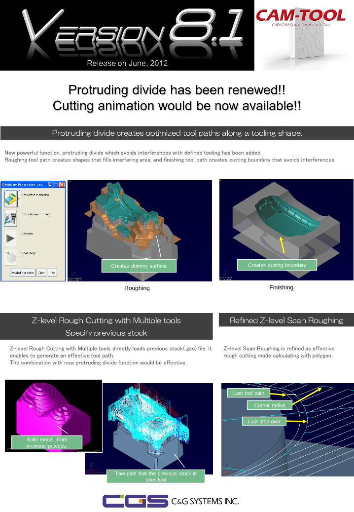
Specify previous stock
Protruding divide creates optimized tool paths along a tooling shape.
Refined Z-level Scan Roughing
Z-level Scan Roughing is refined as effective rough cutting mode calculating with polygon.
Roughing Finishing
Creates cutting boundary
Last tool path
Corner radius
Last step over
Creates dummy surface
Z-level Rough Cutting with Multiple tools directly loads previous stock(.gso) file, it enables to generate an effective tool path. The combination with new protruding divide function would be effective.
Tool path that the previous stock is
specified
Solid modell from
previous process.
New powerful function, protruding divide which avoids interferences with defined tooling has been added. Roughing tool path creates shapes that fills interfering area, and finishing tool path creates cutting boundary that avoids interferences.
Simultaneous 5axis
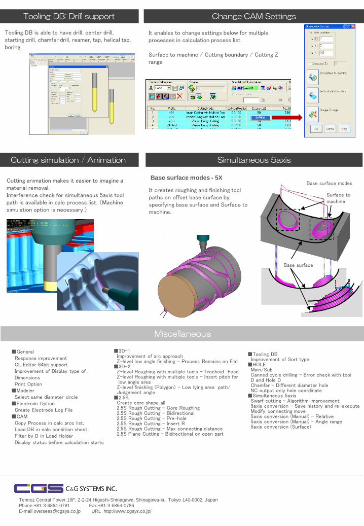
Base surface modes - 5X
It creates roughing and finishing tool paths on offset base surface by specifying base surface and Surface to machine.
Tennoz Central Tower.19F, 2-2-24 Higashi-Shinagawa, Shinagawa-ku, Tokyo 140-0002, Japan
Phone:+81-3-6864-0781 Fax:+81-3-6864-0786
E-mail [email protected] URL http://www.cgsys.co.jp/
Miscellaneous
■3D-1 Improvement of arc approach Z-level low angle finishing – Process Remains on Flat ■3D-2 Z-level Roughing with multiple tools – Trochoid Feed Z-level Roughing with multiple tools – Insert pitch for low angle area Z-level finishing (Polygon) – Low lying area path/ Judgement angle ■2.5S Create core shape all 2.5S Rough Cutting – Core Roughing 2.5S Rough Cutting – Bidirectional 2.5S Rough Cutting – Pre-hole 2.5S Rough Cutting – Insert R 2.5S Rough Cutting – Max connecting distance 2.5S Plane Cutting – Bidirectional on open part
■General Response improvement CL Editor 64bit support Improvement of Display type of Dimensions Print Option ■Modeler Select same diameter circle ■Electrode Option Create Electrode Log File ■CAM Copy Process in calc proc list. Load DB in calc condition sheet. Filter by D in Load Holder Display status before calculation starts
It enables to change settings below for multiple processes in calculation process list. Surface to machine / Cutting boundary / Cutting Z range
Change CAM Settings
■Tooling DB Improvement of Sort type ■HOLE Main/Sub Canned cycle drilling – Error check with tool D and Hole D Chamfer – Different diameter hole NC output only hole coordinate ■Simultaneous 5axis Swarf cutting – Algorithm improvement 5axis conversion – Save history and re-execute Modify connecting move 5axis conversion (Manual) - Relative 5axis conversion (Manual) – Angle range 5axis conversion (Surface)
Tooling DB is able to have drill, center drill, starting drill, chamfer drill, reamer, tap, helical tap, boring.
Tooling DB: Drill support
Base surface modes
Base surface
Surface to machine
Cutting simulation / Animation
Cutting animation makes it easier to imagine a material removal. Interference check for simultaneous 5axis tool path is available in calc process list. (Machine simulation option is necessary.)
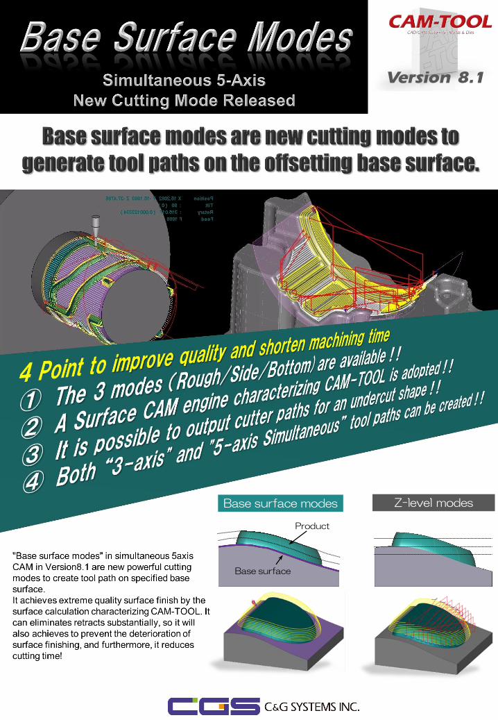
Base surface modes Z-level modes
Product
Base surface
Version 8.1
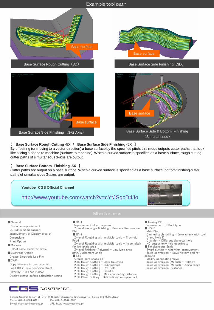
Example tool path
【 Base Surface Rough Cutting -5X / Base Surface Side Finishing -5X 】 By offsetting (or moving to a vector direction) a base surface by the specified pitch, this mode outputs cutter paths that look
like slicing a shape to machine (surface to machine). When a curved surface is specified as a base surface, rough cutting
cutter paths of simultaneous 3-axis are output.
【 Base Surface Bottom Finishing -5X 】 Cutter paths are output on a base surface. When a curved surface is specified as a base surface, bottom finishing cutter
paths of simultaneous 3-axes are output.
Base surface
Base surface
Base surface
Base surface
■General Response improvement CL Editor 64bit support Improvement of Display type of Dimensions Print Option ■Modeler Select same diameter circle ■Electrode Option Create Electrode Log File ■CAM Copy Process in calc proc list. Load DB in calc condition sheet. Filter by D in Load Holder Display status before calculation starts
■3D-1 Improvement of arc approach Z-level low angle finishing – Process Remains on Flat ■3D-2 Z-level Roughing with multiple tools – Trochoid Feed Z-level Roughing with multiple tools – Insert pitch for low angle area Z-level finishing (Polygon) – Low lying area path/Judgement angle ■2.5S Create core shape all 2.5S Rough Cutting – Core Roughing 2.5S Rough Cutting – Bidirectional 2.5S Rough Cutting – Pre-hole 2.5S Rough Cutting – Insert R 2.5S Rough Cutting – Max connecting distance 2.5S Plane Cutting – Bidirectional on open part
■Tooling DB Improvement of Sort type ■HOLE Main/Sub Canned cycle drilling – Error check with tool D and Hole D Chamfer – Different diameter hole NC output only hole coordinate ■Simultaneous 5axis Swarf cutting – Algorithm improvement 5axis conversion – Save history and re-execute Modify connecting move 5axis conversion (Manual) - Relative 5axis conversion (Manual) – Angle range 5axis conversion (Surface)
Miscellaneous
Tennoz Central Tower.19F, 2-2-24 Higashi-Shinagawa, Shinagawa-ku, Tokyo 140-0002, Japan Phone:+81-3-6864-0781 Fax:+81-3-6864-0786 E-mail [email protected] URL http://www.cgsys.co.jp/
Base Surface Rough Cutting(3D) Base Surface Side Finishing(3D)
Base Surface Side & Bottom Finishing
(Simultaneous) Base Surface Side Finishing (3+2 Axis)
Youtube CGS Official Channel
http://www.youtube.com/watch?v=cYtJSgcD4Jo
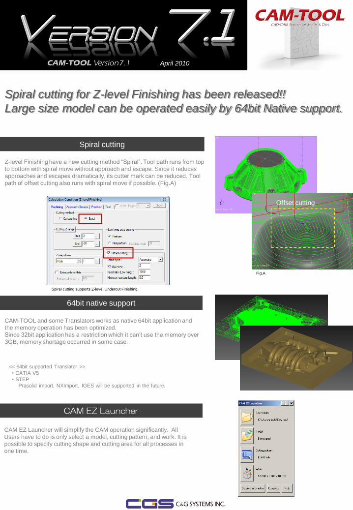
Spiral cutting
Z-level Finishing have a new cutting method “Spiral”. Tool path runs from top
to bottom with spiral move without approach and escape. Since it reduces
approaches and escapes dramatically, its cutter mark can be reduced. Tool
path of offset cutting also runs with spiral move if possible. (Fig.A)
64bit native support
<< 64bit supported Translator >>
・CATIA V5
・STEP
Prasolid import, NXImport, IGES will be supported in the future.
CAM-TOOL and some Translators works as native 64bit application and
the memory operation has been optimized.
Since 32bit application has a restriction which it can’t use the memory over
3GB, memory shortage occurred in some case.
Fig.A
Offset cutting
Spiral cutting supports Z-level Undercut Finishing.
CAM EZ Launcher
CAM EZ Launcher will simplify the CAM operation significantly. All
Users have to do is only select a model, cutting pattern, and work. It is
possible to specify cutting shape and cutting area for all processes in
one time.
April 2010
Spiral cutting for Z-level Finishing has been released!!
Large size model can be operated easily by 64bit Native support.
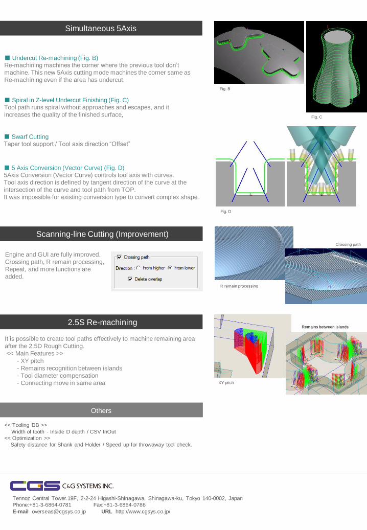
Simultaneous 5Axis
■ Undercut Re-machining (Fig. B) Re-machining machines the corner where the previous tool don’t
machine. This new 5Axis cutting mode machines the corner same as
Re-machining even if the area has undercut.
Tennoz Central Tower.19F, 2-2-24 Higashi-Shinagawa, Shinagawa-ku, Tokyo 140-0002, Japan
Phone:+81-3-6864-0781 Fax:+81-3-6864-0786
E-mail [email protected] URL http://www.cgsys.co.jp/
■ 5 Axis Conversion (Vector Curve) (Fig. D) 5Axis Conversion (Vector Curve) controls tool axis with curves.
Tool axis direction is defined by tangent direction of the curve at the
intersection of the curve and tool path from TOP.
It was impossible for existing conversion type to convert complex shape.
<< Tooling DB >>
Width of tooth - Inside D depth / CSV InOut
<< Optimization >>
Safety distance for Shank and Holder / Speed up for throwaway tool check.
■ Spiral in Z-level Undercut Finishing (Fig. C) Tool path runs spiral without approaches and escapes, and it
increases the quality of the finished surface,
■ Swarf Cutting Taper tool support / Tool axis direction “Offset”
Fig. B
Fig. C
Scanning-line Cutting (Improvement)
Engine and GUI are fully improved.
Crossing path, R remain processing,
Repeat, and more functions are
added.
R remain processing
Crossing path
2.5S Re-machining
It is possible to create tool paths effectively to machine remaining area
after the 2.5D Rough Cutting.
<< Main Features >>
- XY pitch
- Remains recognition between islands
- Tool diameter compensation
- Connecting move in same area XY pitch
Remains between islands
Others
Fig. D
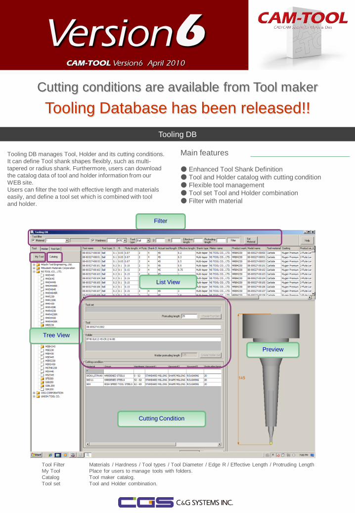
Cutting conditions are available from Tool maker
Tooling Database has been released!!
Version6
CAM-TOOL Version6 April 2010
Tooling DB
Main features
● Enhanced Tool Shank Definition
● Tool and Holder catalog with cutting condition
● Flexible tool management
● Tool set Tool and Holder combination
● Filter with material
Tree View
List View
Cutting Condition
Preview
Tooling DB manages Tool, Holder and its cutting conditions.
It can define Tool shank shapes flexibly, such as multi-
tapered or radius shank. Furthermore, users can download
the catalog data of tool and holder information from our
WEB site.
Users can filter the tool with effective length and materials
easily, and define a tool set which is combined with tool
and holder.
Filter
Tool Filter Materials / Hardness / Tool types / Tool Diameter / Edge R / Effective Length / Protruding Length
My Tool Place for users to manage tools with folders.
Catalog Tool maker catalog.
Tool set Tool and Holder combination.

Curve Control Along Surface-5X
"Curve Control Along Surface-5X“ for simultaneous 5
axis has been released.
- It enables undercut surfaces with spiral.
Enhancement of Z-level Low Angle Finishing
Offset path gets available for low lying area in Z-level Low Angle
Finishing.
《 Partial circumference 》 《 All circumference 》
■ Independent Feed rate (Low lying area)
“Feed rate (Low lying)” has been added. Feed rate for Z-level tool path and
offset path can be specified independently.
■Exclude horizontal area
“Exclude horizontal area“ enables to eliminate tool paths for flat area.
■Multiple cutting area
“Control range“ enables to specify multiple Range surface. It enables to
machine multiple area in one profile.
《 Exclude horizontal area 》
《 Multiple cutting area 》 《 Independent feed rate 》
Enhancement of Optimization
Optimization has new capabilities to check remains and overcut .
The optimization speeds up 2 time or more by refinement of calculation
program.
Optimization setting for Multiple process
《 Additional features 》
《 Curve Control Along Surface-5X 》
《 Overcut 》 《 Remains 》
Optimization conditions and Control
Items for multiple process can be set
in one time to reduce the operation
time and human error.
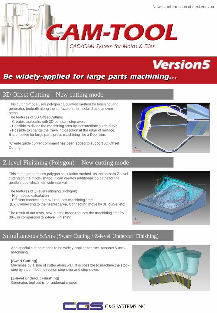
Newest information of next version
Be widely-applied for large parts machining…
3D Offset Cutting – New cutting mode
This cutting mode uses polygon calculation method for finishing, and
generates toolpath along the surface on the model shape at even
steps.
The features of 3D Offset Cutting:
- Creates toolpaths with 3D constant step over.
- Possible to divide the machining area by intermediate guide curve.
- Possible to change the traveling direction at the edge of surface.
It is effective for large parts press machining like a Door trim.
“Create guide curve” command has been added to support 3D Offset
Cutting.
Z-level Finishing (Polygon) – New cutting mode
This cutting mode uses polygon calculation method. Its toolpaths is Z-level
cutting on the model shape. It can creates additional toolpaths for the
gentle slope which has wide interval.
The features of Z-level Finishing (Polygon):
- High speed calculation
- Efficient connecting move reduces machining time.
(Ex. Connecting to the nearest area, Connecting move by 3D curve, etc)
The result of our tests, new cutting mode reduces the machining time by
30% in comparison to Z-level Finishing.
Simultaneous 5Axis (Swarf Cutting / Z-level Undercut Finishing)
Add special cutting modes to be widely-applied for simultaneous 5-axis
machining.
[Swarf Cutting]
Machines by a side of cutter along wall. It is possible to machine the stock
step by step in both direction step-over and step-down.
[Z-level Undercut Finishing]
Generates tool paths for undercut shapes.
Version5
次期バージョン最新情報
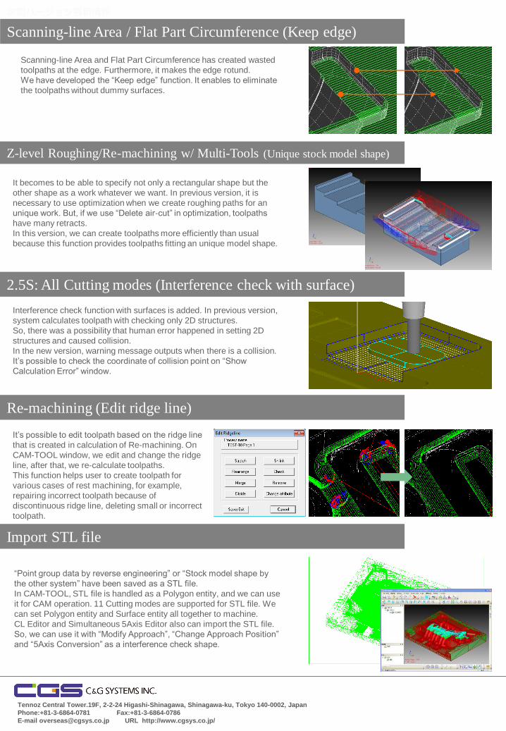
Scanning-line Area / Flat Part Circumference (Keep edge)
Scanning-line Area and Flat Part Circumference has created wasted
toolpaths at the edge. Furthermore, it makes the edge rotund.
We have developed the “Keep edge” function. It enables to eliminate
the toolpaths without dummy surfaces.
Z-level Roughing/Re-machining w/ Multi-Tools (Unique stock model shape)
2.5S: All Cutting modes (Interference check with surface)
It becomes to be able to specify not only a rectangular shape but the
other shape as a work whatever we want. In previous version, it is
necessary to use optimization when we create roughing paths for an
unique work. But, if we use “Delete air-cut” in optimization, toolpaths
have many retracts.
In this version, we can create toolpaths more efficiently than usual
because this function provides toolpaths fitting an unique model shape.
It’s possible to edit toolpath based on the ridge line
that is created in calculation of Re-machining. On
CAM-TOOL window, we edit and change the ridge
line, after that, we re-calculate toolpaths.
This function helps user to create toolpath for
various cases of rest machining, for example,
repairing incorrect toolpath because of
discontinuous ridge line, deleting small or incorrect
toolpath.
Import STL file
Re-machining (Edit ridge line)
Interference check function with surfaces is added. In previous version,
system calculates toolpath with checking only 2D structures.
So, there was a possibility that human error happened in setting 2D
structures and caused collision.
In the new version, warning message outputs when there is a collision.
It’s possible to check the coordinate of collision point on “Show
Calculation Error” window.
“Point group data by reverse engineering” or “Stock model shape by
the other system” have been saved as a STL file.
In CAM-TOOL, STL file is handled as a Polygon entity, and we can use
it for CAM operation. 11 Cutting modes are supported for STL file. We
can set Polygon entity and Surface entity all together to machine.
CL Editor and Simultaneous 5Axis Editor also can import the STL file.
So, we can use it with “Modify Approach”, “Change Approach Position”
and “5Axis Conversion” as a interference check shape.
Tennoz Central Tower.19F, 2-2-24 Higashi-Shinagawa, Shinagawa-ku, Tokyo 140-0002, Japan
Phone:+81-3-6864-0781 Fax:+81-3-6864-0786
E-mail [email protected] URL http://www.cgsys.co.jp/