Ball-nose End Mill for Rough to Semi-finish Cutting SRM2 series … · 2016. 3. 7. · rough...
16
TOOL NEWS Ball-nose End Mill for Rough to Semi-finish Cutting SRM2 series Insert Expansion SRM2 applications offer you the strength of a large radius insert, and the ability to penetrate hard to reach cavities. 2016.2 Update B020A
Transcript of Ball-nose End Mill for Rough to Semi-finish Cutting SRM2 series … · 2016. 3. 7. · rough...

TOOL NEWSBall-nose End Mill for Rough to Semi-finish Cutting
SRM2 series Insert
Expansion
SRM2 applications offer you the strength of a large radius insert, and the ability to penetrate hard to reach cavities.
2016.2 Update B020A

1
SRM2
90°
SRM2
Body features (3-dimensional relief)
Conventional1.7 times
Ø.625", Ø.750", Ø1.000", Ø1.250"
SRM2 applications offer you the strength of a large radius insert, and the ability to penetrate hard to reach cavities.
Ball-Nose End Mill for Rough to Semi-Finish Cutting
Features
High Rigidity
Series Expansion
Highly Heat-resistant Body
Cutting Edge Diameter
Application
Large insert thickness guards against fracture.Thick body core resists body web fracture.
“Streamlined pocket” optimizes a balance of chip flow and body rigidity.
High body rigidity and good chip control, avoid damage from chips welding to the body.
The body of the SRM2 is made of a special alloy steel with excellent high-tempurature strength, enhanced by a corrosion-resistant surface treatment.
In addition to the standard and long cutting edge types, this series has been expanded with a long type which can machine vertical faces. The series is now equipped with a coolant hole as standard, enabling it to tackle a wider range of die mold cutting applications.
Coolant Hole
Long
2
TOUGH-Σ Technology
1055 304 Ti-6Al-4V
P MP6100 0.4
S MP9100 0.3
0.7 0.7 0.7
NEW
2700
2192
2012
1832
1652
1472
12922800 2900 3000 3100
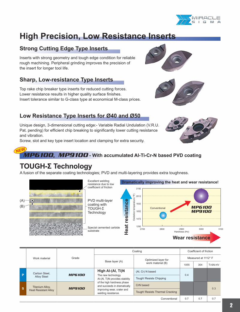
MP6100, MP9100 - With accumulated Al-Ti-Cr-N based PVD coating
A fusion of the separate coating technologies; PVD and multi-layering provides extra toughness.
PVD multi-layer coating with TOUGH-Σ Technology
(A)(B)
Excellent welding resistance due to low coefficient of friction
Special cemented carbide substrate Hardness (Hv)
Conventional
Oxi
datio
n te
mpe
ratu
re (°
F)
Wear resistance
Hea
t res
ista
nce
MP6100
MP9100
Dramatically improving the heat and wear resistance!
Strong Cutting Edge Type Inserts
Sharp, Low-resistance Type Inserts
Low Resistance Type Inserts for Ø40 and Ø50
High Precision, Low Resistance Inserts
Inserts with strong geometry and tough edge condition for reliable rough machining. Peripheral grinding improves the precision of the insert for longer tool life.
Top rake chip breaker type inserts for reduced cutting forces.Lower resistance results in higher quality surface finishes.Insert tolerance similar to G-class type at economical M-class prices.
Unique design, 3-dimensional cutting edge:- Variable Radial Undulation (V.R.U. Pat. pending) for efficient chip breaking to significantly lower cutting resistance and vibration.Screw, slot and key type insert location and clamping for extra security.
Work material Grade
Coating Coefficient of friction
Base layer (A) Optimized layer forwork material (B)
Measured at 1112° F
Carbon Steel, Alloy Steel
High Al-(Al, Ti)NThe new technology Al-(Al, Ti)N provides stability of the high hardness phase and succeeds in dramatically improving wear, crater and welding resistance.
(Al, Cr) N based
Tough! Resists Chipping
Titanium Alloy, Heat Resistant Alloy
CrN based
Tough! Resists Thermal Cracking
Conventional
3
SRM2 Ø40 Ø50
VP15TF
VP30RT
VP20RT
Gray Cast Iron • Ductile Cast Iron Cast Tool Steel Alloy Tool Steel
Low-resistance Cutting Edge Type Inserts (With Breakers)Unique design, 3-dimentional cutting edge:- Variable Radial Undulation (V.R.U. Pat. pending) for efficient chip breaking to significantly lower cutting resistance and vibration. Screw, slot and key type insert location and clamping for extra security.
ToughnessWear Resistance
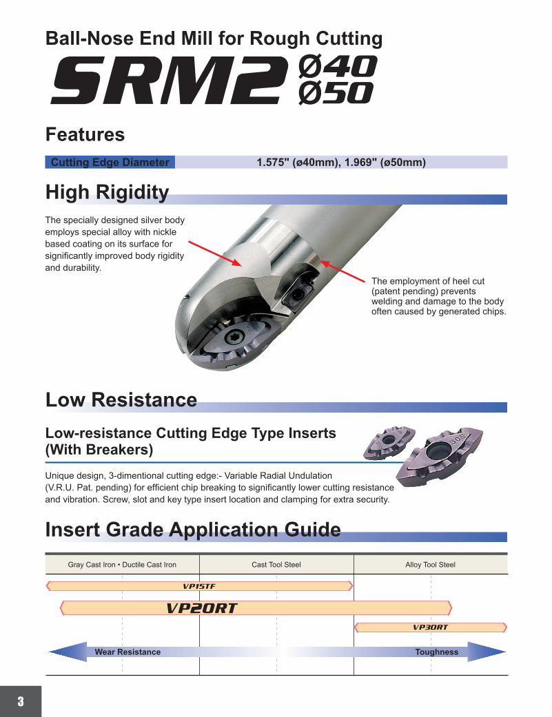
Ball-Nose End Mill for Rough Cutting
1.575" (ø40mm), 1.969" (ø50mm)
FeaturesCutting Edge Diameter
High Rigidity
Low Resistance
Insert Grade Application Guide
The specially designed silver body employs special alloy with nickle based coating on its surface for significantly improved body rigidity and durability.
The employment of heel cut (patent pending) prevents welding and damage to the body often caused by generated chips.

4
SRM2 Ø50
SRM2 Ø50
.625 .3125 .309 .312
.750 .375 .371 .374
1.000 .500 .496 .499
1.250 .625 .621 .624
.625 .616 .6250
.750 .741 .7496
1.000 .991 .9996
1.250 1.241 1.2496
.945''.118''
1350
1125
900
675
150
225
0
Back Force
Feed Force
Principal Force
Feed
Cutting PerformanceComparison of Cutting Resistance
Cutting Conditions
Cut
ting
Res
ista
ne (l
b)
Feed Force Principle ForceBack Force
Chip Geometry
Conventional A
Conventional A
Conventional B
Conventional B
Work piece Ductile cast iron
ToolBall nose end mill with 50mm cutting edge diameter
Cutting Speed 615 SFMTable Feed 42.5 IPM
Depth of Cut .118 inchCutting mode Dry cutting
Radius tolerance and other dimensions when an insert is set in a body
<Radius tolerance>
<Dimensions when an insert is set in a body>
Nominal R
R max.
R min.
Cutting Diameter : DC
Cutting Dia. Nominal R R min. R max.
Cutting Dia. DC min. DC max.

5
R RE DC LF DCON LH LU APMX B2
SRM210SAS2 a 2 .313 .625 4.0 .75 1.5 1.00 .625 3° TS25H ─ zTKY08D ─ SRM210C-M SRM210E-M ─
SRM212SAS2 a 2 .375 .750 4.0 1.00 1.5 1.25 .750 6° 30' TS32 ─ zTKY08D ─ SRM212C
SRM212C-MSRM212ESRM212E-M ─
SRM216SAS2 a 2 .500 1.000 4.5 1.00 2.0 ─ .945 ─ TS43 ─ xTKY15T ─ SRM216C
SRM216C-MSRM216ESRM216E-M ─
SRM220SAS2 a 2 .625 1.250 5.0 1.25 2.0 ─ 1.102 ─ TS55 ─ xTKY25T ─ SRM220C
SRM220C-MSRM220ESRM220E-M ─
SRM210SAM2 a 2 .313 .625 5.0 .75 2.5 1.00 .625 1° 30' TS25H ─ zTKY08D ─ SRM210C-M SRM210E-M ─
SRM212SAM2 a 2 .375 .750 5.0 1.00 2.5 1.25 .750 1° 30' TS32 ─ zTKY08D ─ SRM212C
SRM212C-MSRM212ESRM212E-M ─
SRM216SAM2 a 2 .500 1.000 5.5 1.00 3.0 ─ .945 ─ TS43 ─ xTKY15T ─ SRM216C
SRM216C-MSRM216ESRM216E-M ─
SRM220SAM2 a 2 .625 1.250 6.5 1.25 3.5 ─ 1.102 ─ TS55 ─ xTKY25T ─ SRM220C
SRM220C-MSRM220ESRM220E-M ─
SRM210SAL2 a 2 .313 .625 6.0 .75 3.5 1.00 .625 1° 30' TS25H ─ zTKY08D ─ SRM210C-M SRM210E-M ─
SRM212SAL2 a 2 .375 .750 6.0 1.00 3.5 1.50 .750 1° 30' TS32 ─ zTKY08D ─ SRM212C
SRM212C-MSRM212ESRM212E-M ─
SRM216SAL2 a 2 .500 1.000 6.5 1.25 4.0 1.75 .945 1° 30' TS43 ─ xTKY15T ─ SRM216C
SRM216C-MSRM216ESRM216E-M ─
SRM220SAL2 a 2 .625 1.250 8.0 1.25 5.0 ─ 1.102 ─ TS55 ─ xTKY25T ─ SRM220C
SRM220C-MSRM220ESRM220E-M ─
SRM212SAL4 a 4 .375 .750 6.0 1.00 3.5 1.50 1.180 1° 30' TS32 TS25 zTKY08D
zTKY08D
SRM212CSRM212C-M
SRM212ESRM212E-M
APMT1135PDER-p2
SRM216SAL4 a 4 .500 1.000 6.5 1.25 4.0 1.75 1.457 1° 30' TS43 TS25 xTKY15T
cTKY08F
SRM216CSRM216C-M
SRM216ESRM216E-M
APMT1135PDER-p2
SRM220SAL4 a 4 .625 1.250 8.0 1.25 5.0 ─ 1.732 ─ TS55 TS43 xTKY25T
cTKY15F
SRM220CSRM220C-M
SRM220ESRM220E-M
APMT1604PDER-p2
z x
c
* *
SRM2
a
a
a
a
y
SRM210SAS2SRM212SAS2
SRM210SAL2SRM212SAL2SRM216SAL2
SRM220SAL2
SRM210SAM2SRM212SAM2
SRM212SAL4SRM216SAL4
SRM220SAL4
SRM216SAM2SRM220SAM2
SRM216SAS2SRM220SAS2
P M K N S H
DCON
LFLHRELU
DC
APMX B2
DCON
LFLH
DC
APMX
RE
DCON
LFLH
RE
DC
APMX
DCON
LFLH
RE
DC
APMX
DCON
LFLH
RED
C
APMX
DCONDC
RE APMX
LH
B2
LFLU
DCONDC
REAPMX
LHLF
LU
B2
LF
DCON
APMX
B2
DC
LHLURE
BALL-NOSE END MILL FOR ROUGH TO SEMI-FINISH CUTTING
aAir / coolant through.aSuitable for roughing to semi-finishing of small and
medium molds.aHigh rigidity body design.aLow resistance chipbreaker.aKey type clamp.aShrink fit ready.
Short Type
Long Type
Medium Type
Long Edge Type
Right hand tool holder only.
(Draft Angle) (Draft Angle)
(Draft Angle)(Draft Angle)
SHANK TYPE
* Clamp Torque (lbf-in) : TS25H=8.9, TS25=8.9, TS32=8.9, TS43=31, TS55=66
Roughing
BALL NOSEEND MILL Including
curved faces
a : Inventory maintained.<10 inserts in one case>
Type Order Number Sto
ckNu
mber
of Te
eth
Dimensions (inch)
Inner, Outer Peripheral Inner, Outer Peripheral Inner Outer PeripheralInsert Screw Wrench Insert
Sho
rt M
ediu
mLo
ngLo
ng E
dge

6
MP6
120
MP9
120
VP15
TF RE L W1 S BS
SRM210C-M M a a a .313 .630 .323 .138 ─
SRM212C-M M a a a .375 .748 .385 .169 ─
SRM216C-M M a a a .500 .945 .512 .216 ─
SRM220C-M M a a a .625 1.102 .638 .275 ─
SRM210E-M M a a a .313 .531 .258 .138 ─
SRM212E-M M a a a .375 .610 .315 .169 ─
SRM216E-M M a a a .500 .807 .409 .216 ─
SRM220E-M M a a a .625 .964 .520 .275 ─
SRM212C M a a a .375 .748 .385 .169 ─
SRM216C M a a a .500 .945 .512 .216 ─
SRM220C M a a a .625 1.102 .638 .275 ─
SRM212E M a a a .375 .610 .315 .169 ─
SRM216E M a a a .500 .807 .409 .216 ─
SRM220E M a a a .625 .964 .520 .275 ─
APMT1135PDER-H2 M a .031 .433 .250 .138 .047
APMT1604PDER-H2 M a .031 .650 .375 .187 .055
APMT1135PDER-M2 M a .031 .433 .250 .138 .047
APMT1604PDER-M2 M a .031 .650 .375 .187 .055
=
W1
LRE S
W1
LRE S
W1
LRE S
W1
LRE
S
W1
L
RE
BS
S
W1
L
REB
S
S
SRM
INSERTS
(Note) The M type breaker (APMT....PDER-M2) is the first recommendation for its excellent cutting performance. Please use H type breakers (APMT....PDER-H2) due to cutting edge strength.
(Note) SRM tooling is designed for rough machining applications.*Programming Note: If you choose to use SRM tooling for semi-finishing applications, care must be taken when setting the tool height. The SRM insert includes a chamfer flat at the tip as illustrated. To assist with SRM programming needs, please download our CAD data from our web site; http://www.mitsubishicarbide.com/
Type Shape Order Number
Cla
ss
Coated Dimensions (inch)
Geometry
Inne
r
With
Bre
aker
Out
er
With
Bre
aker
Inne
r
No
Bre
aker
Strong CuttingEdge Type
Out
er
No
Bre
aker
Strong CuttingEdge Type
Per
iphe
ral With
Bre
aker
Strong CuttingEdge Type
With
Bre
aker
Low ResistanceType

7
WT
RE
DC
DC
ON
BD
OA
L
LF L11 H
CR
KS
APM
X
R
SRM2160AM08S30 s Y 8 16 8.5 14.6 48 30 6 10 M8 12 0.1 TS25H ─ zTKY08D SRG16CSRM16C-M
SRG16ESRM16E-M ─
SRM2200AM10S35 s Y 10 20 10.5 18.6 54 35 6 14 M10 14 0.1 TS32 ─ zTKY08D SRG20CSRM20C-M
SRG20ESRM20E-M ─
SRM2250AM12S40 s Y 12.5 25 12.5 23.5 62 40 6 19 M12 19 0.2 TS43 TS25 xTKY15T SRG25CSRM25C-M
SRG25ESRM25E-M ─
SRM2300AM16S45 s Y 15 30 17 28.3 68 45 6 24 M16 24 0.2 TS55 ─ xTKY15TcTKY08F
SRG30CSRM30C-M
SRG30ESRM30E-M ─
SRM2320AM16S45 s Y 16 32 17 30.0 68 45 6 24 M16 28 0.2 TS55 TS43 xTKY25TcTKY15F
SRG32CSRM32C-M
SRG32ESRM32E-M ─
SRM2200AM10L45 s Y 10 20 10.5 18.6 64 45 6 14 M10 30 0.2 TS32 TS25 zTKY08D SRG20CSRM20C-M
SRG20ESRM20E-M
APMT1135PDER-p2
SRM2250AM12L55 s Y 12.5 25 12.5 23.5 77 55 6 19 M12 37 0.3 TS43 TS25 xTKY15TcTKY08F
SRG25CSRM25C-M
SRG25ESRM25E-M
APMT1135PDER-p2
SRM2300AM16L60 s Y 15 30 17 28.3 83 60 6 24 M16 44 0.3 TS55 TS43 xTKY25TcTKY15F
SRG30CSRM30C-M
SRG30ESRM30E-M
APMT1604PDER-p2
SRM2320AM16L60 s Y 16 32 17 29.0 83 60 6 24 M16 44 0.3 TS55 TS43 xTKY25TcTKY15F
SRG32CSRM32C-M
SRG32ESRM32E-M
APMT1604PDER-p2
*1*4 *1z x c
*2
a
a
y
*3
H
CRKS
DCON BD
L11LFRE APMX
DC
OAL
APMXH
CRKS
DCON
BD
L11LFRE
DC
OAL
BALL-NOSE END MILL FOR ROUGH TO SEMI-FINISH CUTTING
Section A-A
Section A-A
METRIC Standard
Right hand tool holder only.
Standard Type
Long Type
SCREW-IN TYPE
*1 Clamp Torque (lbf-in) : TS25H=8.9, TS25=8.9, TS32=8.9, TS43=31, TS55=66
*2 Clamp Torque of the Head (lbf-ft) : M8=17.1, M10=33.8, M12=59.2, M16=66.7
*3 Y=Yes
*4 WT : Mass
a : Inventory maintained. s : Inventory maintained in Japan. <10 inserts in one case>
Type Order Number S
tock
Cool
ant T
hru Dimensions (mm)
R Inner, Outer PeripheralWrench
Inner Outer PeripheralInsert Screw Insert
Sta
ndar
dLo
ng

8
F703
0M
P612
0M
P912
0VP
15TF RE L W1 S BS AN
SRG16C G s s s 8 16 8.2 3.5 ─ 11°SRG20C G s s s 10 19 10.2 4.6 ─ 10°SRG25C G s s s 12.5 24 12.8 5.5 ─ 10°SRG30C G s s s 15 28 15.3 7 ─ 10°SRG32C G s s s 16 28 16.3 7 ─ 10°SRG16E G s s s 8 13.5 6.7 3.5 ─ 11°SRG20E G s s s 10 15.5 8.5 4.6 ─ 9°SRG25E G s s s 12.5 20.5 10.2 5.5 ─ 9°SRG30E G s s s 15 25.2 12.2 7 ─ 9°SRG32E G s s s 16 26.1 13.1 7 ─ 9°SRM16C-M M s s s 8 16 8.2 3.5 ─ 11°SRM20C-M M s s s 10 19 10.2 4.6 ─ 10°SRM25C-M M s s s 12.5 24 12.8 5.5 ─ 10°SRM30C-M M s s s 15 28 15.3 7 ─ 10°SRM32C-M M s s s 16 28 16.3 7 ─ 10°SRM16E-M M s s s 8 13.5 6.7 3.5 ─ 11°SRM20E-M M s s s 10 15.5 8.5 4.6 ─ 9°SRM25E-M M s s s 12.5 20.5 10.2 5.5 ─ 9°SRM30E-M M s s s 15 25.2 12.2 7 ─ 9°SRM32E-M M s s s 16 26.1 13.1 7 ─ 9°APMT1135PDER-H2 M a a 0.8 11 6.35 3.5 1.2 11°APMT1604PDER-H2 M a a 0.8 16.5 9.525 4.76 1.4 11°
APMT1135PDER-M2 M a a 0.8 11 6.35 3.5 1.2 11°APMT1604PDER-M2 M a a 0.8 16.5 9.525 4.76 1.4 11°
*
=
W1
LRE S AN
AN
W1
LRE S
AN
W1
LRE S
ANW1
LRE S
AN
RE
BS
W1
L S
AN
RE
BS
W1
L S
18°
18°
SRM
INSERTS For Metric Standard
(Low-resistance inner or outer inserts are precision M class type.)
* Selection guide for peripheral cutting edges : The first recommendation is the super sharp M breaker (APMT....PDER-M2).When cutting edge strength is particularly important, use the H breaker (APMT....PDER-H2).
(Note) SRM tooling is designed for rough machining applications.*Programming Note: If you choose to use SRM tooling for semi-finishing applications, care must be taken when setting the tool height. The SRM insert includes a chamfer flat at the tip as illustrated. To assist with SRM programming needs, please download our CAD data from our web site; http://www.mitsubishicarbide.com/
Type Shape Order Number
Cla
ss
Coated Dimensions (mm)
Geometry
Inne
r
Strong CuttingEdge Type
Out
er
Strong CuttingEdge Type
Inne
r
Low ResistanceType
Out
er
Low ResistanceType
Per
iphe
ral
Strong CuttingEdge Type
Low ResistanceType

9
a b c
.625"
4
1.5 5.5
2.5 6.5
3.5 7.5
.750"
1.5 5.5
2.5 6.5
3.5 7.5
1.000"
2.0 6.0
3.0 7.0
4.0 8.0
1.250"
2.0 6.0
3.5 7.5
5.0 9.0
ap max
.
DC
a
c
b
BALL-NOSE END MILL FOR ROUGH TO SEMI-FINISH CUTTING
RECOMMENDED CUTTING CONDITIONS
Peripheral
Max
imum
cut
ting
edge
leng
th
Inner/Outer
(Long cutting edge type)
Tool Overhang
Recommended Depth of Cut for Long Cutting Edge Type
Recommended cutting conditions on this literature are chosen based on deflection, vibration and machined surface when using a CAT50 arbor. Conditions-"a" is the length from a gage line to the arbor end face, and "b" is the neck length (tool overhang from the arbor).
The maximum cutting edge length of the long cutting edge type with a peripheral insert is 1.4-1.5DC. The peripheral insert is for light machining only. Please refer the recommended cutting condition or page 12.
(Inch)
Cutting Diameter : DC Type
Short
Medium
Long
Short
Medium
Long
Short
Medium
Long
Short
Medium
Long

10
& .625" & .750" &1.000" &1.250"RPM IPM ap RPM IPM ap RPM IPM ap RPM IPM ap
P180-280HB
525MP6120 VP15TF
3183 15 .236 2546 12 .315 2037 19 .492 1698 16 .591
395 3183 15 .236 2546 12 .315 2037 19 .492 1698 16 .591
655 3183 15 .157 2546 12 .157 2037 19 .236 1698 16 .295
280-350HB
460MP6120 VP15TF
2785 13 .236 2228 11 .315 1783 17 .492 1485 14 .591
395 2785 13 .236 2228 11 .315 1783 17 .492 1485 14 .591
525 2785 13 .157 2228 11 .157 1783 17 .236 1485 14 .295
35-45HRC
395MP6120 VP15TF
2387 11 .236 1910 9 .315 1528 14 .492 1273 12 .472
330 2387 11 .236 1910 9 .315 1528 14 .492 1273 12 .472
525 2387 11 .157 1910 9 .157 1528 14 .236 1273 12 .177
≤350HB
460MP6120 VP15TF
2785 13 .236 2228 11 .315 1783 21 .394 1485 23 .295
395 2785 13 .236 2228 11 .315 1783 21 .394 1485 23 .295
525 2785 13 .157 2228 11 .157 1783 21 .197 1485 23 .177
M≤270HB
655
VP15TF
3979 19 .157 3183 15 .197 2546 30 .236 2122 33 .591
330 3979 19 .157 3183 15 .197 2546 30 .236 2122 33 .591
820 3979 19 .118 3183 15 .118 2546 24 .157 2122 25 .177
K≤350MPa
655
VP15TF
3979 31 .236 3183 25 .315 2546 40 .492 2122 33 .591
490 3979 31 .236 3183 25 .315 2546 40 .492 2122 33 .591
985 3979 31 .157 3183 25 .157 2546 40 .295 2122 33 .177
≤500MPa
590
VP15TF
3581 28 .236 2865 23 .315 2292 36 .492 1910 30 .591
490 3581 28 .236 2865 23 .315 2292 36 .492 1910 30 .591
785 3581 28 .157 2865 23 .157 2292 36 .295 1910 30 .177
≤800MPa
525
VP15TF
3183 25 .236 2546 20 .315 2037 32 .492 1698 27 .591
490 3183 25 .236 2546 20 .315 2037 32 .492 1698 27 .591
820 3183 25 .157 2546 20 .157 2037 32 .295 1698 27 .177
S≤350HB
165
MP9120
995 4 .157 796 3 .157 637 3 .236 531 2 .295
100 995 4 .157 796 3 .157 637 3 .236 531 2 .295
195 995 4 .079 796 3 .079 637 3 .157 531 2 .118
─
165
MP9120
995 4 .157 796 3 .157 637 3 .236 531 2 .295
100 995 4 .157 796 3 .157 637 3 .236 531 2 .295
195 995 4 .079 796 3 .079 637 3 .157 531 2 .118
H45-50HRC
330
VP15TF
1989 9 .157 1591 8 .157 1273 10 .236 1061 8 .295
195 1989 9 .157 1591 8 .157 1273 10 .236 1061 8 .295
395 1989 9 .079 1591 8 .079 1273 10 .157 1061 8 .118
50-60HRC
195
VP15TF
1194 6 .157 955 5 .157 764 6 .236 637 5 .295
130 1194 6 .157 955 5 .157 764 6 .236 637 5 .295
330 1194 6 .079 955 5 .079 764 6 .157 637 5 .118
ySLOT MILLING
Cut
ting
Mod
e
Work Material HardnessCuttingSpeed(SFM)
Grade Type
Carbon SteelAlloy Steel
Short
Medium
Long
Short
Medium
Long
Pre-Hardened Steel
Short
Medium
Long
Alloy Tool Steel
Short
Medium
Long
Stainless Steel
Short
Medium
Long
Gray Cast Iron
Short
Medium
Long
Ductile Cast Iron
Short
Medium
Long
Short
Medium
Long
Titanium Alloy
Short
Medium
Long
Heat-resistant Alloy
Short
Medium
Long
Heat Treated Steel
Short
Medium
Long
Short
Medium
Long
N : Spindle Speed (RPM)F : Table Feed (IPM)

11
& .625" & .750" &1.000" &1.250"RPM IPM ap ae RPM IPM ap ae RPM IPM ap ae RPM IPM ap ae
P180-280HB
655MP6120 VP15TF
3979 31 .157 .236 3183 38 .197 .315 2546 50 .236 .394 2122 50 .295 .394
525 3979 31 .157 .236 3183 38 .197 .315 2546 50 .236 .394 2122 50 .295 .394
820 3979 25 .157 .157 3183 25 .197 .236 2546 50 .236 .295 2122 50 .295 .295
280-350HB
525MP6120 VP15TF
3183 20 .157 .236 2546 20 .197 .315 2037 32 .236 .394 1698 33 .295 .394
395 3183 20 .157 .236 2546 20 .197 .315 2037 32 .236 .394 1698 33 .295 .394
655 3183 15 .157 .157 2546 16 .197 .236 2037 24 .236 .295 1698 20 .295 .295
35-45HRC
525MP6120 VP15TF
3183 20 .157 .236 2546 20 .197 .315 2037 32 .236 .394 1698 33 .295 .394
395 3183 20 .157 .236 2546 20 .197 .315 2037 32 .236 .394 1698 33 .295 .394
655 3183 15 .157 .157 2546 16 .197 .236 2037 24 .236 .295 1698 27 .295 .295
≤350HB
525MP6120 VP15TF
3183 20 .157 .236 2546 20 .197 .315 2037 32 .236 .394 1698 33 .295 .394
395 3183 20 .157 .236 2546 20 .197 .315 2037 32 .236 .394 1698 33 .295 .394
655 3183 15 .157 .157 2546 16 .197 .236 2037 24 .236 .295 1698 20 .295 .295
M≤270HB
655
VP15TF
3979 19 .157 .236 3183 20 .197 .315 2546 30 .236 .394 2122 33 .295 .394
330 3979 19 .157 .236 3183 20 .197 .315 2546 30 .236 .394 2122 33 .295 .394
820 3979 19 .157 .157 3183 15 .197 .236 2546 24 .236 .295 2122 33 .295 .295
K≤350MPa
655
VP15TF
3979 63 .157 .315 3183 63 .197 .394 2546 60 .236 .394 2122 58 .295 .394
490 3979 63 .157 .315 3183 63 .197 .394 2546 60 .236 .394 2122 58 .295 .394
985 3979 47 .157 .236 3183 50 .197 .315 2546 60 .236 .394 2122 58 .295 .236
≤500MPa
655
VP15TF
3979 63 .157 .315 3183 63 .197 .394 2546 60 .236 .394 2122 50 .295 .394
490 3979 63 .157 .315 3183 63 .197 .394 2546 60 .236 .394 2122 50 .295 .394
920 3979 47 .157 .236 3183 50 .197 .315 2546 60 .236 .394 2122 50 .295 .236
≤800MPa
590
VP15TF
3581 56 .157 .315 2865 56 .197 .394 2292 54 .236 .394 1910 45 .295 .394
490 3581 56 .157 .315 2865 56 .197 .394 2292 54 .236 .394 1910 45 .295 .394
820 3581 42 .157 .236 2865 45 .197 .315 2292 54 .236 .394 1910 45 .295 .236
S≤350HB
165
MP9120
995 12 .157 .157 796 9 .157 .197 637 8 .236 .236 531 6 .295 .118
100 995 12 .157 .157 796 9 .157 .197 637 8 .236 .236 531 6 .295 .118
195 995 12 .079 .079 796 9 .079 .118 637 8 .157 .157 531 6 .118 .059
─
165
MP9120
995 12 .157 .157 796 9 .157 .197 637 8 .236 .236 531 6 .295 .118
100 995 12 .157 .157 796 9 .157 .197 637 8 .236 .236 531 6 .295 .118
195 995 12 .079 .079 796 9 .079 .118 637 8 .157 .157 531 6 .118 .059
H45-50HRC
330
VP15TF
1989 9 .157 .157 1591 8 .197 .197 1273 10 .236 .295 1061 8 .295 .118
195 1989 9 .157 .157 1591 8 .197 .197 1273 10 .236 .295 1061 8 .295 .118
395 1989 9 .157 .079 1591 8 .197 .118 1273 10 .236 .157 1061 8 .295 .059
50-60HRC
195
VP15TF
1194 6 .157 .157 955 5 .197 .197 764 6 .236 .295 637 5 .295 .118
130 1194 6 .157 .157 955 5 .197 .197 764 6 .236 .295 637 5 .295 .118
330 1194 6 .157 .079 955 5 .197 .118 764 6 .236 .157 637 5 .295 .059
y
ap
ae
BALL-NOSE END MILL FOR ROUGH TO SEMI-FINISH CUTTING
Cut
ting
Mod
e
SHOULDER MILLING (Cutting Depth : Small)
N : Spindle Speed (RPM)F : Table Feed (IPM)
Work Material HardnessCuttingSpeed(SFM)
Grade Type
Carbon SteelAlloy Steel
Short
Medium
Long
Short
Medium
Long
Pre-Hardened Steel
Short
Medium
Long
Alloy Tool Steel
Short
Medium
Long
Stainless Steel
Short
Medium
Long
Gray Cast Iron
Short
Medium
Long
Ductile Cast Iron
Short
Medium
Long
Short
Medium
Long
Titanium Alloy
Short
Medium
Long
Heat-resistant Alloy
Short
Medium
Long
Heat Treated Steel
Short
Medium
Long
Short
Medium
Long
RECOMMENDED CUTTING CONDITIONS

12
y
& .625" & .750" &1.000" &1.250"RPM IPM ap ae RPM IPM ap ae RPM IPM ap ae RPM IPM ap ae
P180-280HB
655MP6120 VP15TF
3979 25 .315 .157 3183 30 .394 .157 2546 50 .492 .197 2122 50 .591 .177
525 3979 25 .315 .157 3183 30 .394 .157 2546 50 .492 .197 2122 50 .591 .177
820 3979 19 .315 .118 3183 20 .394 .118 2546 40 .492 .157 2122 33 .591 .118
280-350HB
525MP6120 VP15TF
3183 15 .315 .157 2546 20 .394 .157 2037 32 .492 .197 1698 33 .591 .177
395 3183 15 .315 .157 2546 20 .394 .157 2037 32 .492 .197 1698 33 .591 .177
655 3183 15 .315 .118 2546 12 .394 .118 2037 24 .492 .157 1698 20 .591 .118
35-45HRC
525MP6120 VP15TF
3183 15 .315 .157 2546 20 .394 .157 2037 32 .492 .197 1698 33 .591 .177
395 3183 15 .315 .157 2546 20 .394 .157 2037 32 .492 .197 1698 33 .591 .177
655 3183 15 .315 .118 2546 12 .394 .118 2037 24 .492 .157 1698 20 .591 .118
≤350HB
525MP6120 VP15TF
3183 15 .315 .157 2546 20 .394 .157 2037 32 .492 .197 1698 33 .591 .177
395 3183 15 .315 .157 2546 20 .394 .157 2037 32 .492 .197 1698 33 .591 .177
655 3183 15 .315 .118 2546 12 .394 .118 2037 24 .492 .098 1698 20 .591 .118
M≤270HB
655
VP15TF
3979 19 .315 .157 3183 20 .394 .157 2546 30 .492 .394 2122 33 .591 .394
330 3979 19 .315 .157 3183 20 .394 .157 2546 30 .492 .394 2122 33 .591 .394
820 3979 19 .315 .118 3183 15 .394 .118 2546 24 .492 .157 2122 20 .591 .177
K≤350MPa
655
VP15TF
3979 47 .315 .315 3183 50 .394 .315 2546 50 .492 .394 2122 58 .591 .394
490 3979 47 .315 .315 3183 50 .394 .315 2546 50 .492 .394 2122 58 .591 .394
985 3979 38 .315 .197 3183 38 .394 .157 2546 50 .492 .295 2122 42 .591 .177
≤500MPa
655
VP15TF
3979 47 .315 .315 3183 50 .394 .315 2546 50 .492 .394 2122 50 .591 .394
490 3979 47 .315 .315 3183 50 .394 .315 2546 50 .492 .394 2122 50 .591 .394
920 3979 38 .315 .197 3183 38 .394 .157 2546 50 .492 .295 2122 33 .591 .177
≤800MPa
590
VP15TF
3581 42 .315 .315 2865 45 .394 .315 2292 45 .492 .394 1910 45 .591 .394
490 3581 42 .315 .315 2865 45 .394 .315 2292 45 .492 .394 1910 45 .591 .394
820 3581 34 .315 .197 2865 34 .394 .157 2292 45 .492 .295 1910 30 .591 .177
S≤350HB
165
MP9120
995 8 .157 .079 796 6 .157 .118 637 5 .236 .157 531 4 .295 .118
100 995 8 .157 .079 796 6 .157 .118 637 5 .236 .157 531 4 .295 .118
195 995 8 .079 .039 796 6 .079 .079 637 5 .157 .059 531 4 .118 .059
─
165
MP9120
995 8 .157 .079 796 6 .157 .118 637 5 .236 .157 531 4 .295 .118
100 995 8 .157 .079 796 6 .157 .118 637 5 .236 .157 531 4 .295 .118
195 995 8 .079 .039 796 6 .079 .079 637 5 .157 .059 531 4 .118 .059
H45-50HRC
330
VP15TF
1989 9 .315 .079 1591 8 .394 .118 1273 10 .492 .157 1061 8 .591 .118
195 1989 9 .315 .079 1591 8 .394 .118 1273 10 .492 .157 1061 8 .591 .118
395 1989 9 .315 .039 1591 8 .394 .079 1273 8 .492 .059 1061 4 .591 .059
50-60HRC
195
VP15TF
1194 6 .315 .079 955 5 .394 .118 764 6 .492 .157 637 5 .591 .118
130 1194 6 .315 .079 955 5 .394 .118 764 6 .492 .157 637 5 .591 .118
330 1194 6 .315 .039 955 5 .394 .079 764 5 .492 .059 637 3 .591 .059
ap
aeCut
ting
Mod
e
SHOULDER MILLING (Cutting Depth : Large)*Machining Stainless SteelsDown cutting (Climb milling) is preferred.
N : Spindle Speed (RPM)F : Table Feed (IPM)
Work Material HardnessCuttingSpeed(SFM)
Grade Type
Carbon SteelAlloy Steel
Short
Medium
Long
Short
Medium
Long
Pre-Hardened Steel
Short
Medium
Long
Alloy Tool Steel
Short
Medium
Long
Stainless Steel
Short
Medium
Long
Gray Cast Iron
Short
Medium
Long
Ductile Cast Iron
Short
Medium
Long
Short
Medium
Long
Titanium Alloy
Short
Medium
Long
Heat-resistant Alloy
Short
Medium
Long
Heat Treated Steel
Short
Medium
Long
Short
Medium
Long

13
SRM2 Ø40 (1.575")Ø50 (1.969 ")
R RE DC DCON LF LH APMX
SRM2400WNLS s 2 .787 1.575 2.000 7.874 4.724 2.126 TS6S TS43 TKY30T TKY15F SRG40C SRG40E APMT1604PDER-p2
SRM2500WNLS s 2 .984 1.969 2.000 7.874 4.724 2.480 TS6 TS43 TKY30T TKY15F SRG50C SRG50E APMT1604PDER-p2
SRM2400WNLM s 2 .787 1.575 2.000 9.843 6.693 2.126 TS6S TS43 TKY30T TKY15F SRG40C SRG40E APMT1604PDER-p2
SRM2500WNLM s 2 .984 1.969 2.000 9.843 6.693 2.480 TS6 TS43 TKY30T TKY15F SRG50C SRG50E APMT1604PDER-p2
SRM2500WNLL s 2 .984 1.969 2.000 11.811 8.661 2.480 TS6 TS43 TKY30T TKY15F SRG50C SRG50E APMT1604PDER-p2
SRM2500WNLX s 2 .984 1.969 2.000 13.780 10.630 2.480 TS6 TS43 TKY30T TKY15F SRG50C SRG50E APMT1604PDER-p2
SRM2400SNLS s 2 .787 1.575 1.654 7.874 3.937 2.126 TS6S TS43 TKY30T TKY15F SRG40C SRG40E APMT1604PDER-p2
SRM2500SNLS s 2 .984 1.969 1.654 7.874 3.937 2.480 TS6 TS43 TKY30T TKY15F SRG50C SRG50E APMT1604PDER-p2
SRM2400SNLM s 2 .787 1.575 1.654 9.843 5.906 2.126 TS6S TS43 TKY30T TKY15F SRG40C SRG40E APMT1604PDER-p2
SRM2500SNLM s 2 .984 1.969 1.654 9.843 3.937 2.480 TS6 TS43 TKY30T TKY15F SRG50C SRG50E APMT1604PDER-p2
SRM2500MNLS s 2 .984 1.969 ─ 10.079 4.724 2.480 TS6 TS43 TKY30T TKY15F SRG50C SRG50E APMT1604PDER-p2
SRM2500MNLM s 2 .984 1.969 ─ 11.260 5.906 2.480 TS6 TS43 TKY30T TKY15F SRG50C SRG50E APMT1604PDER-p2
* *
VP15
TFVP
20R
TVP
30R
T
RE L W1 S BS
SRG40C G s s s .787 1.417 .807 .315 ─SRG50C G s s s .984 1.575 1.024 .335 ─
SRG40E G s s s .787 1.260 .654 .315 ─SRG50E G s s s .984 1.409 .787 .335 ─
APMT1604PDER-M2 M a .031 .650 .375 .187 .055
APMT1604PDER-H2 M a .031 .650 .375 .187 .055
*
*
*
*
a
a a
P M K N S H
DCO
N
LFLHRE
DC
APMX
DCO
N
LFLHRE
DC
APMX
LFLH
M20
RE
DC
APMX
W1
LRE S
W1
LRE S
W1
L
RE
BS
S
W1
L
RE
BS
S
BALL-NOSE END MILL FOR ROUGH TO SEMI-FINISH CUTTING
Combination Type
Morse Taper Type Straight Type
Right hand tool holder only.METRIC Standard
* Clamp Torque (lbf-in) : TS43=31, TS6=89, TS6S=89
INSERTS
Strong Cutting Edge Type
a : Inventory maintained. s : Inventory maintained in Japan.<10 inserts in one case>
* 2 inserts in one case.
Roughing
BALL NOSEEND MILL
Includingcurved faces
Type Order Number Sto
ckNu
mbe
r of F
lutes
Dimensions (inch)
Inner, Outer Peripheral Inner, Outer Peripheral Inner Outer PeripheralInsert Wrench Insert
Com
bina
tion Sta
ndard
Long
Ext
ra L
ong
Stra
ight
Standa
rdLo
ng
Morse
Tape
r
Standa
rdLo
ng
App
licat
ion
Shape Order Number
Cla
ss
Coated Dimensions (inch)
Geometry
Inne
rO
uter
Per
iphe
ral
VP15TF
VP30RT
VP20RT
14
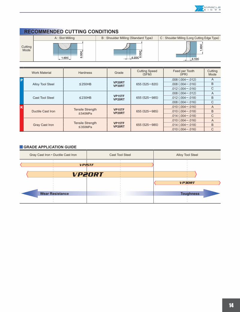
P<250HB VP20RT
VP30RT 655 (525─820).008 (.004─ .012) A.008 (.004─ .016) B.012 (.004─ .016) C
<230HB VP15TFVP20RT 655 (525─985)
.008 (.004─ .012) A
.012 (.004─ .018) B
.008 (.004─ .016) CK
VP15TFVP20RT 655 (525─985)
.010 (.004─ .016) A
.010 (.004─ .018) B
.014 (.004─ .018) C
VP15TFVP20RT 655 (525─985)
.010 (.004─ .016) A
.014 (.004─ .018) B
.010 (.004─ .016) C
y
DC
DC
DC
DC
DC
DC
RECOMMENDED CUTTING CONDITIONS
GRADE APPLICATION GUIDE
Wear Resistance Toughness
Gray Cast Iron • Ductile Cast Iron Cast Tool Steel Alloy Tool Steel
Work Material Hardness Grade Cutting Speed(SFM)
Feed per Tooth(IPR)
CuttingMode
PAlloy Tool Steel
Cast Tool Steel
KDuctile Cast Iron Tensile Strength
<540MPa
Gray Cast Iron Tensile Strength<350MPa
CuttingMode
A : Slot Milling B : Shoulder Milling (Standard Type) C : Shoulder Milling (Long Cutting Edge Type)

SRM220SAL2 SRM220SAM2SRM220C-M, SRM220E-M SRM220C-M, SRM220E-M
540 37027.5 11.8.009 .005
.197-.315 .197.197 .591
SRM2500WNML SRM2500WNLSVP15TF VP20RT
1200 120023.6-47.5 23.6.394-.591 .197-.787
.276 .394
URL : (Tools specifications subject to change without notice.)
LOS ANGELES HEAD OFFICE11250 Slater Avenue, Fountain Valley, CA 92708TEL : 714-352-6100 FAX : 714-668-1320
CHICAGO OFFICE1314B North Plum Grove Road, Schaumburg, IL 60173TEL : 847-252-6300 FAX : 847-519-1732
TORONTO OFFICE3535 Laird Road, Units 15 & 16, Mississauga, Ontario, L5L 5Y7, CanadaTEL : 905-814-0240 FAX : 905-814-0245
MMC METAL DE MEXICO, S.A. DE C.V.Av. La Cañada No.16, Parque Industrial Bernardo Quintana,El Marques, Queretaro, CP76246, MexicoTEL : +52-442-221-6136 FAX : +52-442-221-6134
Customer Service : 800-523-0800Technical Service : 800-486-2341
Avoiding screws/bolts seizingIn order to avoid screws/bolts seizing, the application of a special lubricant MK1K (separately sold) is recommended when setting inserts on end mills.
Printed in U.S.A. 1/14
For Your SafetyaDon't handle inserts and chips without gloves. aPlease machine within the recommended application range and exchange expired tools with new ones in advance of breakage. aPlease use safety covers and wear safety glasses. aWhen using compounded cutting oils, please take fire precautions. aWhen attaching inserts or spare parts, please use only the correct wrench or driver. aWhen using rotating tools, please make a trial run to check run-out, vibration and abnormal sounds etc.
Application ExamplesTool
InsertMachine Horizontal machining center Double housing planing machining center
Work Piece
Gray cast iron Alloy steel
Component Press mold Forging mold
Cut
ting
Con
ditio
ns Cutting Speed (SFM)Table Feed (IPM)Feed per Tooth (IPT)Depth of Cut (inch)Width of Cut (inch)Cutting mode Air blow Air blow
ResultsCompared to a conventional ball nose end mill, the SRM2 has offered better cutting performance, made smaller cutting noise and lengthen tool life 1.5 fold.
Compared to a conventional ball nose end mill, the SRM2 has offered betting cutting performance, made smaller cutting noise and lengthen tool life 1.3 fold.
Tool
InsertMachine 2 way machining Zigzag machining
Work Piece
Ductile Cast Iron Die Steel
Component Press mold Press mold
Cutti
ng C
ondi
tions Revolution (min)
Table Feed (IPM)Depth of Cut (inch)Pick Feed (inch)Cutting mode Dry Dry
Results
Compared to a conventional product, tool life has become about 1.3 - 2 times longer.Small cutting noise and excellent chip disposal enabled unmanned machining at night.
Compared to a conventional product, tool life has become about 2 time longer.Unmanned machining has been achieved without unexpected insert fracture.Small cutting noise and stable cutting performance.


![[SR4] SRM2-04 Thrash the Body Electric](https://static.fdocuments.in/doc/165x107/544c349cb1af9f6e7d8b48df/sr4-srm2-04-thrash-the-body-electric.jpg)