Yankee Surface Chatter – Mechanics, Monitoring and Methods ...
12
Printed with permission of UBM Asia Trade Fairs Pte Ltd. Presented at Tissue World 2011, March 28-31, 2011, Nice, France ABSTRACT Chatter is one of the most insidious issues that can develop on the Yankee dryer. It is a term that is often used to describe observations made about sheet, coat- ing and Yankee surface defects. Its presence can lead to waste, lost time and result in increased maintenance and capital expenditures. Conditions that lead to the appearance of chatter are often traced to doctor tip vibrations and are frequently related to mechanical issues or process operating conditions. Over the last decade the appearance of chatter on Yankee dryers has increased dramatically and most of the issues seem to be related to the management of the creping process. Once conditions exist that can cause the tip of the doc- tor blade to vibrate, the amplitude can be intensified by resonance responses with other machine components. This review focuses on process driven chatter and discusses three areas surrounding this phenomena: 1) Mechanics (how it forms) 2) Monitoring (how to develop early warning) 3) Methods (practical ways to eliminate and/or avoid the appearance of chatter). INTRODUCTION In the day to day operation of the tissue machine operators are continually challenged to achieve higher levels of productivity and quality. The quest for these improvements often results in a process that strays toward the outer edges of the operating window. Excursions beyond the limits of the process can result in creping conditions that lead to onset of chatter. By understanding the mechanics of the phenomena and the current best practices for monitoring, a set of protocols can be developed that lead to avoidance of chatter in the coating and on the Yankee surface. During the last two decades there has been a marked improvement in the ability to monitor the mechanical integrity of the tissue machine. It is a rare occurrence By Sam Archer, Gary Furman, William Von Drasek, Nalco Company, Naperville, IL Yankee Surface Chatter – Mechanics, Monitoring and Methods to Minimize Impact that the tissue machine mechanically fails. What has been observed with increasing frequency is a functional failure around the creping process. The creping process is a complex transformation involv- ing mechanical, chemical and operational elements. When these elements are fully functioning they define the operating window of the process. The best way to avoid chatter is to understand the different elements and their operational limits. A functional failure is an excursion beyond the capability of the process and does not imply that an element is broken. Often processes in a functional failed state can lead to a mechanical failure, a loss of process continuity and increased waste. This condition is referred to as a “process driven” failed state. MECHANICS OF PROCESS DRIVEN CHATTER A good way to eliminate chatter is to first start by understanding it. The formation of chatter on the Yankee surface is a process anomaly. A number of reviews have been presented that help the tissue maker understand how chatter occurs (Corboy 2003, Alessandrini 2003). The following discussion builds on this previous work. It focuses on the tip of the creping doctor blade and the influence of process conditions that can lead to onset of chatter. Since chatter manifests at the tip of the doctor blade it is important to understand the interacting forces at this location. A simplistic, but understandable model has been previously presented (Corboy 2003, Apple 2007). This model attempts to describe forced vibration of the total mass between the strong back loading cylinders and the creping doctor blade. A modified recreation of this model is shown in Figure 1. If consideration is given to the relationship of higher frequency vibration and the occurrences of chatter, a special focus should be given to understanding Reprint R-1012
Transcript of Yankee Surface Chatter – Mechanics, Monitoring and Methods ...
Printed with permission of UBM Asia Trade Fairs Pte Ltd. Presented at Tissue World 2011, March 28-31, 2011, Nice, France
ABSTRACTChatter is one of the most insidious issues that can develop on the Yankee dryer. It is a term that is often used to describe observations made about sheet, coat-ing and Yankee surface defects. Its presence can lead to waste, lost time and result in increased maintenance and capital expenditures. Conditions that lead to the appearance of chatter are often traced to doctor tip vibrations and are frequently related to mechanical issues or process operating conditions. Over the last decade the appearance of chatter on Yankee dryers has increased dramatically and most of the issues seem to be related to the management of the creping process.
Once conditions exist that can cause the tip of the doc-tor blade to vibrate, the amplitude can be intensified by resonance responses with other machine components. This review focuses on process driven chatter and discusses three areas surrounding this phenomena:
1) Mechanics (how it forms)
2) Monitoring (how to develop early warning)
3) Methods (practical ways to eliminate and/or avoid the appearance of chatter).
INTRODUCTIONIn the day to day operation of the tissue machine operators are continually challenged to achieve higher levels of productivity and quality. The quest for these improvements often results in a process that strays toward the outer edges of the operating window. Excursions beyond the limits of the process can result in creping conditions that lead to onset of chatter. By understanding the mechanics of the phenomena and the current best practices for monitoring, a set of protocols can be developed that lead to avoidance of chatter in the coating and on the Yankee surface.During the last two decades there has been a marked improvement in the ability to monitor the mechanical integrity of the tissue machine. It is a rare occurrence
By Sam Archer, Gary Furman, William Von Drasek, Nalco Company, Naperville, IL
Yankee Surface Chatter –Mechanics, Monitoring and Methods to Minimize Impact
that the tissue machine mechanically fails. What has been observed with increasing frequency is a functional failure around the creping process. The creping process is a complex transformation involv-ing mechanical, chemical and operational elements. When these elements are fully functioning they define the operating window of the process. The best way to avoid chatter is to understand the different elements and their operational limits. A functional failure is an excursion beyond the capability of the process and does not imply that an element is broken. Often processes in a functional failed state can lead to a mechanical failure, a loss of process continuity and increased waste. This condition is referred to as a “process driven” failed state.
MECHANICS OF PROCESS DRIVEN CHATTER
A good way to eliminate chatter is to first start by understanding it. The formation of chatter on the Yankee surface is a process anomaly. A number of reviews have been presented that help the tissue maker understand how chatter occurs (Corboy 2003, Alessandrini 2003). The following discussion builds on this previous work. It focuses on the tip of the creping doctor blade and the influence of process conditions that can lead to onset of chatter. Since chatter manifests at the tip of the doctor blade it is important to understand the interacting forces at this location. A simplistic, but understandable model has been previously presented (Corboy 2003, Apple 2007). This model attempts to describe forced vibration of the total mass between the strong back loading cylinders and the creping doctor blade. A modified recreation of this model is shown in Figure 1. If consideration is given to the relationship of higher frequency vibration and the occurrences of chatter, a special focus should be given to understanding
Reprint R-1012
motion of the doctor blade tip (See Figure 2). Equa-tion 1 (Corboy 2003) provides a general mathematical description for motion within these systems but does not address what initiates the movement.
Fsin(ωt) = m(dx2/dt2) + c dx/dt + kx (Eq. 1)
Fsin(ωt) = Motion of a the mass within the systemm = Mass of the systemc = Dampening Constantk = System stiffness factor (k1 and k2)x = Displacement from the origint = Time
Figure 1 – Dampened spring system used as basic model for describing forced doctor blade vibration. (Adapted from Corboy 2003).
Figure 2 – Mechanical factors that affect the movement of the doctor blade tip.
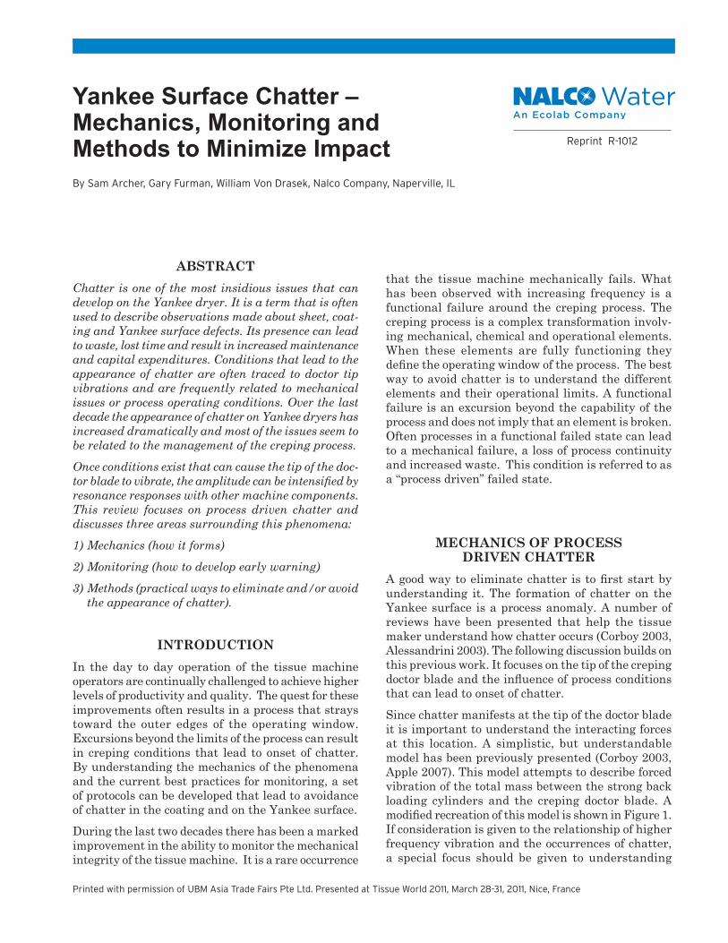
Figure 3 – A demonstration of out of plane movement. and chatter that can be formed.
Previous work (Archer 2008) further described pro-cess driven chatter as sheet, coating and Yankee surface defects related to a phenomena known as stick-slip (See Figure 3). The phenomenon causes excessive vibration at the tip of the doctor blade and increased out of plane movement. Excessive out of plane vibration can lead to chatter (See Figure 3). In this work a number of forces and creping elements are defined (See Figure 4). All of these elements are part of a system that defines the creping operating window.

TANGENTIAL RESISTANCEA critical force within the system, as defined in Figure 4, is tangential resistance. A review of numerous chatter events would indicate that this is the main factor that has increased over the last two decades. In an effort to improve productivity or quality, mill operations have driven for more and more adhesion of the sheet to dryer. This desire for more adhesion has resulted in thicker, harder coatings that cause greater tangential resistance at the doctor blade tip. Often so much resistance develops at the tip of the doctor blade that it can no longer stay within the boundaries of the coating and lifts up (out of plane). This is the beginning of the stick slip phenomena, which leads to increased doctor tip vibration and ultimately chatter. The amount of tangential resistance is directly re-lated to many factors. Figure 5 is a closer view of the area around the tip of a creping doctor blade. A functional expression for tangential resistance is shown in Equation 2.
Figure 4 – The Creping System- Mechanics, Chemistry, Operations.
Figure 5 – Forces and coating characteristics around the tip of the creping doctor blade. The coating/fiber mass (m) and shear modulus (G’), can significantly influence the total tangential resistance.

Tangential Resistance ⇒ƒ[(μkFN), (mΔv), G’, Cx, P] (Eq.2)
Where: -FN = normal force of the doctor blade tip-μk = coefficient of kinetic friction, dependent on surface characteristics. -m = mass of coating material, mc, and sheet, ms, on the dryer. The mass associated with the sheet is a function of basis weight and a sheet adhesion factor, A, (0 to 1). m = (mc+msA) -n = surface velocity of Yankee moving the coating and sheet into contact with the tip of the creping doctor blade -G’ = elastic behavior of the coating developed on the Yankee at the current velocity.-Cx = tendency of the coating adhesive to become hard or react with other chemistries in the process.-θ = Set up Angle-P = pocket angle, P = (90 - θ + a).
One of the most important items leading to increased tangential resistance is the coating that develops on the Yankee surface. The amount of, m, and the physi-cal characteristics, G’, will dramatically influence the resistance that the doctor blade will encounter. It should be remembered that coatings on the Yankee surface are not pure substances, but composites made of many different materials (Sloan 2006, Furman 2007, Boudreau 2009). A conceptual drawing of a Yankee coating is shown in Figure 6.As would be expected with a composite, the character-istics are usually significantly different than the neat binding material. In the case of the composite that develops on the Yankee surface the characteristics are defined by all of the included materials, the type of binding materials, any modifiers and the operating environment. Some soluble process chemistries react
Figure 7 – Impact of various components commonly found in Yankee coatings on shear storage modulus, G’.
with the adhesive binder while others precipitate and form solid structures within the matrix. Non-soluble fibrous cellulosic materials and other inorganic sol-ids tend to act as mechanical reinforcing structures significantly affecting the shear modulus (G’) of the coating. All of these components act to make the coating significantly harder than the adhesive binder. Figure 7 illustrates the impact of different included materials on a commercial Yankee coating adhesive. The higher the shear storage modulus, G’, the harder the coating will be.
Figure 6 – Conceptual drawing of a Yankee coating.
The environment around the creping doctor blade is very dynamic. There are a number of conditions that can develop that lead to hard, tangentially resistant Yankee coatings. Many of the interactions have been documented in the past (Archer 2008, Grigoriev, 2008) and are summarized in Table 1. As the items in the table demonstrate most tissue making process changes or chemistries result in a thicker, harder more tangentially resistant coating.

Table 1 – Typical impacts of process conditions and additive usage on tangential resistance. (Note: Based on qualitative and quantitative observations.)
Table 1 – Typical impacts of process conditions and additive usage on tangential resistance. (Note: Based on qualitative and quantitative observations.)
Process Condition or
Additive
Impact on Composite
Coating Shear Modulus – G’
Impact on Binding Adhesive
Coating Hardness
Tangential Resistance
Potential Issues
Lower Moisture Creping
-Increases -Drier - Lower Adhesion -Stronger internal binding
-Harder -Higher -Picks and breaks -Short operational Dr. life -Chatter
Strength Additives
-Increases -Potential higher MW -Some chemically crosslink with coating adhesive
-Harder -Higher -Picks and breaks -Short Dr. life -Chatter -Loss of sheet Control
Increased Yankee Speed
-Increases -Less time for binder and composite to absorb energy of blade
-Harder -Higher -Loss of sheet control -Loss of effective Adhesion
Debonder -Decreases -Lower adhesion -Interferes with binder
-Softer -Lower -Loss of sheet control -Loss of adhesion
Hemi-cellulose
-Increases -Lower adhesion -Interact with binder
-Harder -Higher -Loss of sheet control -Loss of adhesion
Fines -Increases -Lower adhesion -Interact with Binder
-Harder -Higher -Loss of sheet control -Loss of adhesion
Calcium Carbonate
-Increases -Lower adhesion -Interact with binder
-Harder -Higher -Loss of sheet control -Loss of adhesion
Spray on Softener
-Decreases -Lower adhesion -Interferes with binder
-Softer -Lower -Loss of sheet control -Streaky coating
Increase Total Add-on
-Increases -Higher Adhesion -Harder -Higher -Picks and breaks -Short Dr. Life -Chatter
Increased Adhesive to Release Ratio
-Increases -Higher Adhesion -Harder -Higher -Picks and breaks -Short Dr. Life -Chatter
MAP -Increases -Higher Adhesion -Lower G’
-Harder -Higher -Picks and breaks -Short operational Dr. life -Chatter

MONITORING THE PROCESS Controlling the process to avoid chatter almost al-ways involves frequent monitoring. Those that have been successful are involved in both qualitative and quantitative data acquisition and decision making. Qualitative information is usually obtained through time based inspections of the process. Quantitative condition based monitoring of the system yields real time information about changes that are occurring in the tissue making system. Neither of the monitoring technologies will guarantee the elimination of all dam-age or lost time but they will provide operators with useful information for productive problem solving and process interventions. Tables 2 and 3 below should help operators identify out of norm process excursions that may need to be addressed.
Vibration Monitoring – “Best Available Technology”Continuous on-line vibration monitoring, to detect the onset of chatter, provides improved runnability and as-set protection. Chatter that is developing in the coating is often corrected by adjusting chemical add-on rates and ratios or reconditioning the Yankee surface with a doctor blade change. In cases where coating build-up and chatter in the coating is severe, the dryer surface may require short-term maintenance that involves a shutdown and sanding of the dryer. The sanding re-moves residual coating and smoothes out the surface. Early detection of the onset of chatter and execution of these corrective steps reduces the risk of damaging the metal dryer surface with chatter marks. Once the metal dryer surface becomes damaged, it can only be repaired through the costly operation of regrinding the surface. Regrinding also accelerates asset depreciation due to a reduction in the dryer wall thickness that can negatively affect the vessel pressure rating. Utilization of an on-line monitoring system to detect doctor blade vibration is possible using piezoelectric accelerometers strategically mounted near the creping doctor blade. These sensors have a small footprint and are hermetically sealed making them well suited for the dusty moist environment. Direct mounting of the accelerometers on the doctor blade is not practical be-cause of the geometric constraints and limited service lifetime of the blade. Therefore, indirect monitoring is practiced by mounting the sensors on the doctor holder as shown in Figure 8. In this configuration, vibration originating at the doctor blade propagates through the doctor blade holder to the sensor. At least two sen-sors are recommended in order to observe side to side variation in the vibration levels that may be present across the Yankee width.
Table 2 – Qualitative time based observations of Yankee surface.
Figure 8 – Accelerometer mounting option on the crepe blade holder for chatter monitoring.
Table 3 – Quantitative continuous monitoring of tissue making process. Yankee Load Vibration Moisture Profiles Monitoring Monitor both CD Check for increased Identify no and MD profiles. Yankee drive load chatter baseline that can indicate vibration Variation can lead excessive tangential characteristics. to uneven coating resistance. characteristics, Check for higher tangential Increased load may résistance and resistance and be due to either excursions in chatter. coating characteristics both frequency or doctor blade wear. and amplitude. Identify and eliminate source of vibration.
Bright Light Strobe Light Yankee EdgesCheck for thick or Check for appearance Check forthin coating. of cracked glass appearance of → Hard edge depositCheck for streaky → Must work tocoating remove. Leads to chatter. Check for appearance of corrugation → Chatter Check for indication of wear Chatter. on doctor blades on Yankee surface.

Accelerometers are point measurements that integrate vibration propagating through the process to the sen-sor. Discrimination of vibration frequencies originat-ing from other sources such as fan pumps, screens, felts, bearings and rolls is made by monitoring higher frequency bands associated with doctor tip vibration and potential coating chatter. An example, illustrat-ing frequency and amplitude changes that occur from chatter is shown in Figure 9. The images show a series of vibration frequency spectra collected over several days. The left hand image shows vibration frequency data collected under normal operating conditions when there was no evidence of coating chatter and no prod-uct quality issues. Data collected during this period represents a baseline condition. The characteristic features in this set of frequency spectral data show similar band structures and amplitudes. Conversely, the right hand image shows significant changes in amplitude of selected frequency bands as well as the appearance of new high amplitude bands. These new bands appeared when chatter was observed in the coating. In practice, alarm levels are set on selected frequency bands to alert operators when the amplitude exceeds a set level. When an alarm condition arises, the operator can follow a decision tree protocol to determine the appropriate course of corrective action.Another example illustrating useful information ob-tained from on-line vibration monitoring is the varia-tion in the doctor blade energy resulting from changes in tangential resistance. In this case, it is convenient to monitor the RMS (Root Mean Square) amplitude of the time waveform data collected from the accelerometer. The RMS reduces the complex time waveform data to a single value useful for trending overall doctor holder vibration energy. The trend plot presented in Figure 10 shows the dynamic behavior of the vibration energy for
creping and cleaning doctor blade changes. When a doc-tor blade is changed the RMS value drops dramatically. This is due to significant removal of coating material from the Yankee surface with a new, sharp tipped, blade and resultant lower tangential resistance. As the blade ages and the coating begins to build-up, the tangential resistance increases causing the RMS to increase. The rate of change for the RMS increase can vary as well as the maximum value reached before a blade change. It has been observed that the rate of change and peak value can be dramatically affected by adjustments to the Yankee coating and the mechanical set-up and operation of the doctor blade and holder.
Figure 9 – Vibration frequency spectra data collected over several days for coating with and without chatter based on visual inspection. When chatter is present the amplitude of the high frequency bands increases as well as the appearance of additional excited bands at other frequencies.
Figure 9 - Vibration frequency spectra data collected over several days for coating with and without chatter based on visual inspection. When chatter is present the amplitude of the high frequency bands increases as well as the appearance of additional excited bands at other frequencies.
Another example illustrating useful information obtained from on-line vibration monitoring is the variation in the doctor blade energy resulting from changes in tangential resistance. In this case, it is convenient to monitor the RMS (Root Mean Square) amplitude of the time waveform data collected from the accelerometer. The RMS reduces the complex time waveform data to a single value useful for trending overall doctor holder vibration energy. The trend plot presented in Figure 10 shows the dynamic behavior of the vibration energy for creping and cleaning doctor blade changes. When a doctor blade is changed the RMS value drops dramatically. This is due to significant removal of coating material from the Yankee surface with a new, sharp tipped, blade and resultant lower tangential resistance. As the blade ages and the coating begins to build-up, the tangential resistance increases causing the RMS to increase. The rate of change for the RMS increase can vary as well as the maximum value reached before a blade change. It has been observed that the rate of change and peak value can be dramatically affected by adjustments to the Yankee coating and the mechanical set-up and operation of the doctor blade and holder.
Figure 10 – Real time RMS run chart showing increased amplitude over the life of a doctor blade. Note the drop in RMS when doctor blades are changed.
METHODS TO MANAGE THE PROCESSIf active monitoring of the Yankee surface indicates chatter conditions are developing, process interven-tions can be made in a systematic, timely way to abate the condition. Since chatter is a system failure, all the critical system elements around the tip of the doctor blade need to be considered (See Figure 4). The most probable condition that will be encountered is a hardening of the coating resulting in an increase in tangential resistance. This resistance must be either mechanically addressed to maintain stable operations or the resistance due to the coating must be reduced.
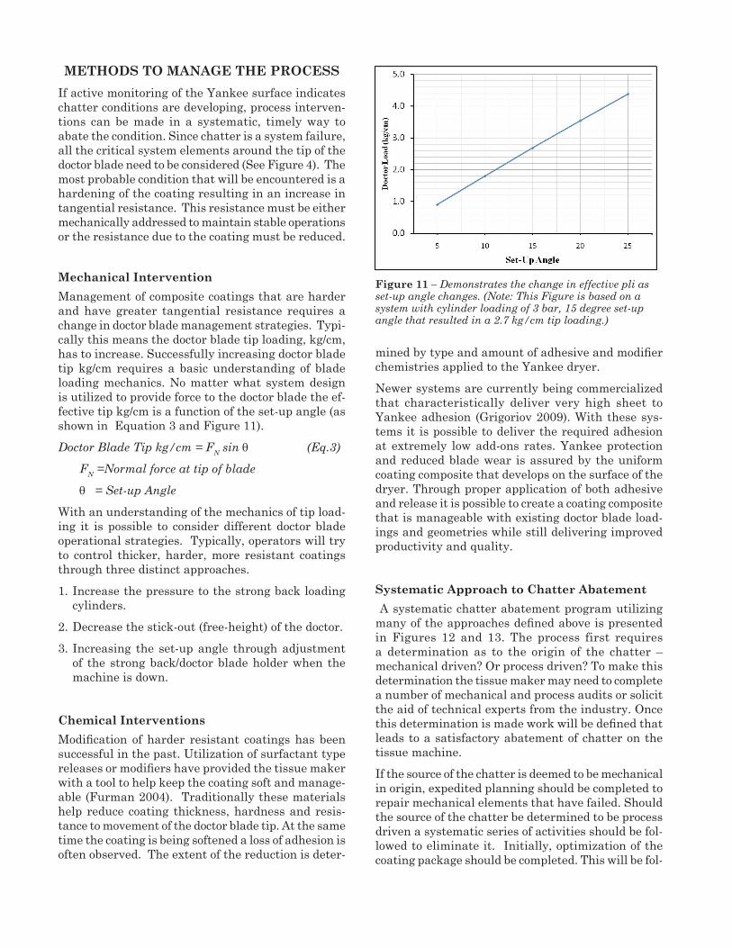
Mechanical InterventionManagement of composite coatings that are harder and have greater tangential resistance requires a change in doctor blade management strategies. Typi-cally this means the doctor blade tip loading, kg/cm, has to increase. Successfully increasing doctor blade tip kg/cm requires a basic understanding of blade loading mechanics. No matter what system design is utilized to provide force to the doctor blade the ef-fective tip kg/cm is a function of the set-up angle (as shown in Equation 3 and Figure 11).Doctor Blade Tip kg/cm = FN sin θ (Eq.3)
FN =Normal force at tip of blade
θ = Set-up Angle
With an understanding of the mechanics of tip load-ing it is possible to consider different doctor blade operational strategies. Typically, operators will try to control thicker, harder, more resistant coatings through three distinct approaches. 1. Increase the pressure to the strong back loading
cylinders. 2. Decrease the stick-out (free-height) of the doctor.3. Increasing the set-up angle through adjustment
of the strong back/doctor blade holder when the machine is down.
Chemical InterventionsModification of harder resistant coatings has been successful in the past. Utilization of surfactant type releases or modifiers have provided the tissue maker with a tool to help keep the coating soft and manage-able (Furman 2004). Traditionally these materials help reduce coating thickness, hardness and resis-tance to movement of the doctor blade tip. At the same time the coating is being softened a loss of adhesion is often observed. The extent of the reduction is deter-
mined by type and amount of adhesive and modifier chemistries applied to the Yankee dryer.Newer systems are currently being commercialized that characteristically deliver very high sheet to Yankee adhesion (Grigoriov 2009). With these sys-tems it is possible to deliver the required adhesion at extremely low add-ons rates. Yankee protection and reduced blade wear is assured by the uniform coating composite that develops on the surface of the dryer. Through proper application of both adhesive and release it is possible to create a coating composite that is manageable with existing doctor blade load-ings and geometries while still delivering improved productivity and quality.
Systematic Approach to Chatter Abatement A systematic chatter abatement program utilizing many of the approaches defined above is presented in Figures 12 and 13. The process first requires a determination as to the origin of the chatter – mechanical driven? Or process driven? To make this determination the tissue maker may need to complete a number of mechanical and process audits or solicit the aid of technical experts from the industry. Once this determination is made work will be defined that leads to a satisfactory abatement of chatter on the tissue machine. If the source of the chatter is deemed to be mechanical in origin, expedited planning should be completed to repair mechanical elements that have failed. Should the source of the chatter be determined to be process driven a systematic series of activities should be fol-lowed to eliminate it. Initially, optimization of the coating package should be completed. This will be fol-
Figure 11 – Demonstrates the change in effective pli as set-up angle changes. (Note: This Figure is based on a system with cylinder loading of 3 bar, 15 degree set-up angle that resulted in a 2.7 kg/cm tip loading.)

Figure 13 – Systematic methodology to abate process driven chatter. (Note: If any of the interventions above result in elimination of chatter, further changes to the process should be suspended until a full evaluation can be completed.)
Figure 12 – Basic definition of origin of tissue machine chatter.
lowed by focused attention on doctor blade mechanics. A number of loading, stick-out and set-up moves are recommended that will result in increased doctor tip penetration and ability to maintain effective move-ment through the coating. Chemical modifications will need to be made if mechanical doctor blade ad-justments are unsuccessful. If none of the solutions outlined below eliminate the appearance of chatter on the Yankee dryer, operations will need to re-start from the beginning and test basic assumptions as to the origin of the chatter.
CONCLUSIONSChatter is a process anomaly that can negatively affect quality production and asset availability. The phenomenon has been tied to excessive vibration at the doctor blade tip. Many occurrences of chatter are directly related to process changes. In general the changes have resulted in composite coatings that are thicker, harder and more tangentially resistant. These more resistant coatings interfere with the abil-ity of the doctor blade tip to move within acceptable boundaries of the Yankee coating. This often leads to out of plane movement, excessive vibration and the onset of chatter. Currently, there are operational and best available technologies that allow time based or condition based monitoring of the process. This infor-mation is critical to problem solving, decision making, and planning. Control and elimination of conditions that lead to excessive doctor blade vibration and surface chatter requires systematic process interven-tions. The approach integrates mechanical, chemical and operational changes to the system. With disci-plined application of the suggested changes process driven chatter can usually be reduced or eliminated.
REFERENCESAlessandrini, A., Pagani, P., “Chatter Marks: Origin, Evolution and Influence of the Creping Doctors”, Tissue World, Nice, France, March 2003.Apple, Chan Lok Shun, www.personal.cityu.edu.hk/~bsapplec,/forced.htm.Archer, S., Grigoriev, V., Furman, G., Bonday, L., Su, W., Chatter and Soft Tissue Production: Process Driven Mechanisms”, Tissue World Americas Confer-ence, Miami, Florida, March 2008.Boudreau, J., Hollmark, H., “Chemical and Morpho-logical Analysis of Tissue Yankee Coating”, Nordic Pulp and Paper Research J., Vol. 24, no. 1, 52 -59, 2009.

Corboy, W., “Vibration Induced Yankee Surface Wear – An Overview of Chatter,” Tissue World Conference, Nice France, March 27, 2003.Furman, G., “Effects of Modifying Agents on Adhesive Film Properties – Findings Toward Improved Yankee Coatings”, Tissue World Americas Conference, Miami, Florida, September 2004.Furman, G., “Yankee Coating Chemistry”, Karlstad Tissue Conference, Karlstad Sweden, April 18, 2007.Grigoriev, V., Furman, G., Frette, G., New High Adhesion Creping Technology for Improved Sheet Properties and Energy Savings”, Tissue World, Nice, France, March 2009.
Grigoriev, V., Furman, G., Archer, S., Su, W., Kaley, C., “Wet-end Impacts on the Creping Transforma-tion” PTS Tissue Symposium, Munich, Germany, March 2008. Sloan, J., “Trouble Shooting Coatings”, Tissue Run-nability Course, Covington, KY, October 2006.
ACKNOWLEDGEMENTSThe authors would like to thank Winston Su (Nalco) for his contributions to this work.


Nalco Water, an Ecolab CompanyNorth America: 1601 West Diehl Road • Naperville, Illinois 60563 • USA Europe: Richtistrasse 7 • 8304 Wallisellen • SwitzerlandAsia Pacific: 2 International Business Park • #02-20 The Strategy Tower 2 • Singapore 609930Greater China: 18G • Lane 168 • Da Du He Road • Shanghai China • 200062Latin America: Av. Francisco Matarazzo • nº 1350 • Sao Paulo – SP Brazil • CEP: 05001-100
ecolab.com/nalco-water
Ecolab, Nalco Water and the logos are Trademarks of Ecolab USA Inc.©2011, 2016, 2018 Ecolab USA Inc. All Rights Reserved 02/18