Xiaoyu Sun Xiaofeng Cao - Technical University of … Sun Xiaofeng Cao Kgs. Lyngby 2004 IMM...
98
Xiaoyu Sun Xiaofeng Cao Kgs. Lyngby 2004 IMM –THESIS -2004-24
Transcript of Xiaoyu Sun Xiaofeng Cao - Technical University of … Sun Xiaofeng Cao Kgs. Lyngby 2004 IMM...
Xiaoyu Sun Xiaofeng Cao
Kgs. Lyngby 2004 IMM –THESIS -2004-24

Preface The present report is the documentation of Master Thesis project, which is submitted in candidacy for the M.Sc degree of Computer Systems Engineering from the Technical University of Denmark (DTU). The work described in the project has been developed under the Division for Computer Science and Engineering (CSE), at the department of Informatics and Mathematical Modelling (IMM) in DTU. Mr. Paul Fischer has supervised this project. We would like to express our sincere gratitude to our supervisor Paul Fischer, not only for the great support and many inspiring conversation, but also the tireless effort on improving the manuscripts we have worked on. Say thanks to him for his careful perusal of this project and useful comments. We would like to thank Professor Flemming Nielson for helping us to find this project. We also would like to thank Mr. Flemming Stassen for giving us some good and helpful advice of the project. Finally, we would like to thank all other teachers in DTU for teaching us the relevant knowledge and say thanks to all the people for helping and supporting us during our studies in DTU.
Kongens Lyngby 20th, April, 2004 _____________________________ ___________________________
Xiaoyu Sun Xiaofeng Cao

Abstract A generic database is a collection of data and the database management system (DBMS) is the software which manages and controls access to the database. A database is shared Database systems are everywhere in our lives nowadays. A database is a shared collection of logically related data, together with a description of this data, designed to meet the information needs of an organization. The database is a single repository of data which can be defined once and used simultaneously by many departments and users. A DBMS is a software system which can enable users to define, create, and maintain the database and provide controlled access to this database. Thus the DMBS is the software which can interact with the use’s application programs and the database. Choosing a Relational Database Management System (RDBMS) is a mature, prevalent, theoretically well-founded and efficient way of storing structured data. The development of database is a catalyst for developments in software engineering. In this thesis project, we will adopt some suitable technologies of database development to realize a specific application of database focused on university education and professional career. Keywords: database, DMBS, alumni net, RDBMS, E/R model, Access, Java, JDBC,
Socket-Client.
1
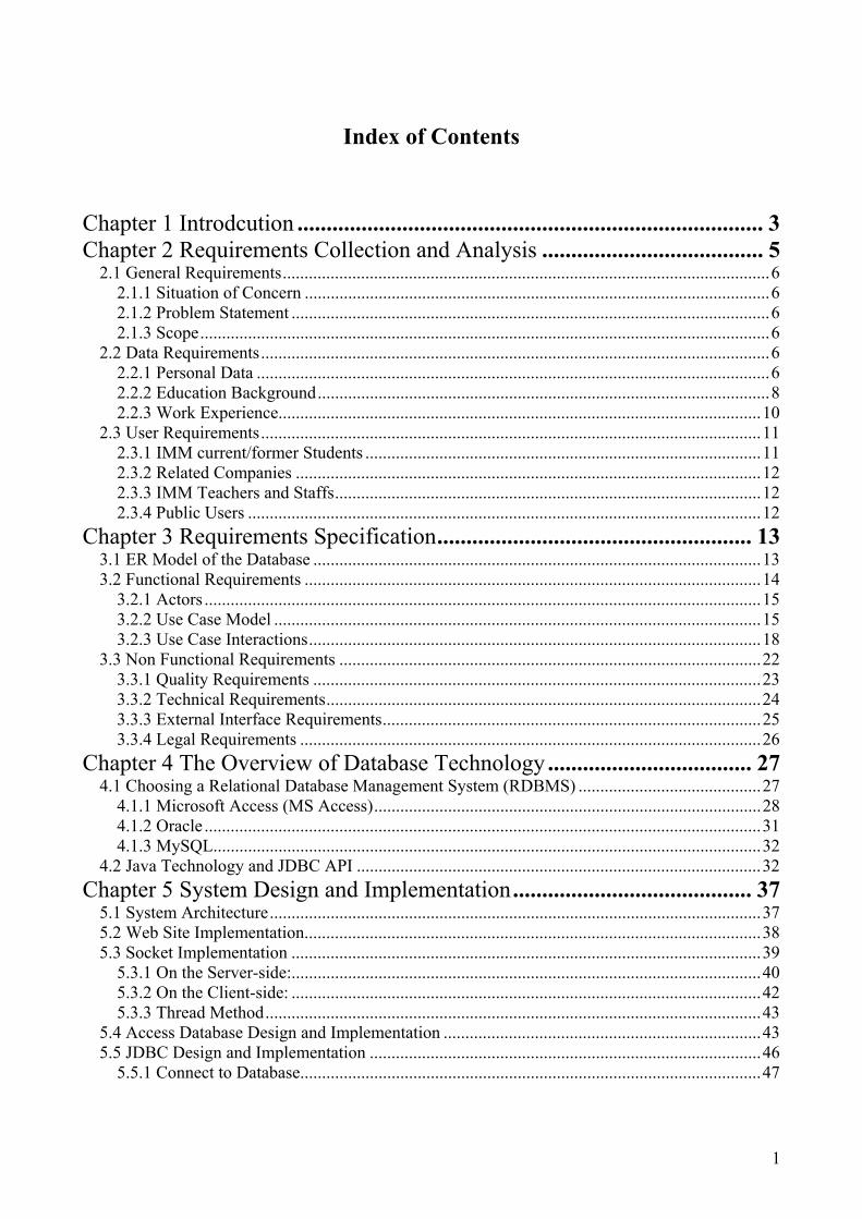
Index of Contents Chapter 1 Introdcution ................................................................................ 3 Chapter 2 Requirements Collection and Analysis ...................................... 5
2.1 General Requirements................................................................................................................6 2.1.1 Situation of Concern ...........................................................................................................6 2.1.2 Problem Statement ..............................................................................................................6 2.1.3 Scope...................................................................................................................................6
2.2 Data Requirements.....................................................................................................................6 2.2.1 Personal Data ......................................................................................................................6 2.2.2 Education Background........................................................................................................8 2.2.3 Work Experience...............................................................................................................10
2.3 User Requirements...................................................................................................................11 2.3.1 IMM current/former Students ...........................................................................................11 2.3.2 Related Companies ...........................................................................................................12 2.3.3 IMM Teachers and Staffs..................................................................................................12 2.3.4 Public Users ......................................................................................................................12
Chapter 3 Requirements Specification...................................................... 13 3.1 ER Model of the Database .......................................................................................................13 3.2 Functional Requirements .........................................................................................................14
3.2.1 Actors ................................................................................................................................15 3.2.2 Use Case Model ................................................................................................................15 3.2.3 Use Case Interactions........................................................................................................18
3.3 Non Functional Requirements .................................................................................................22 3.3.1 Quality Requirements .......................................................................................................23 3.3.2 Technical Requirements....................................................................................................24 3.3.3 External Interface Requirements.......................................................................................25 3.3.4 Legal Requirements ..........................................................................................................26
Chapter 4 The Overview of Database Technology ................................... 27 4.1 Choosing a Relational Database Management System (RDBMS) ..........................................27
4.1.1 Microsoft Access (MS Access).........................................................................................28 4.1.2 Oracle ................................................................................................................................31 4.1.3 MySQL..............................................................................................................................32
4.2 Java Technology and JDBC API .............................................................................................32 Chapter 5 System Design and Implementation ......................................... 37
5.1 System Architecture.................................................................................................................37 5.2 Web Site Implementation.........................................................................................................38 5.3 Socket Implementation ............................................................................................................39
5.3.1 On the Server-side:............................................................................................................40 5.3.2 On the Client-side: ............................................................................................................42 5.3.3 Thread Method..................................................................................................................43
5.4 Access Database Design and Implementation .........................................................................43 5.5 JDBC Design and Implementation ..........................................................................................46
5.5.1 Connect to Database..........................................................................................................47
2
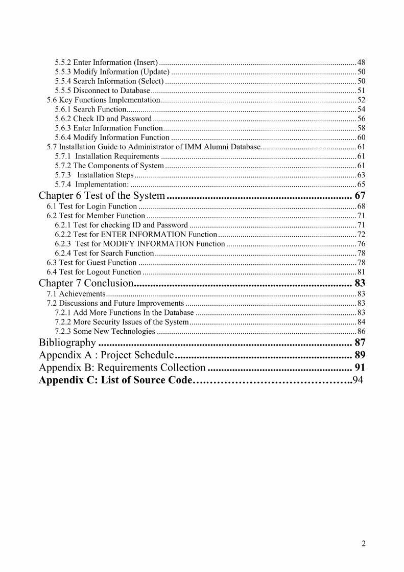
5.5.2 Enter Information (Insert) .................................................................................................48 5.5.3 Modify Information (Update) ...........................................................................................50 5.5.4 Search Information (Select) ..............................................................................................50 5.5.5 Disconnect to Database.....................................................................................................51
5.6 Key Functions Implementation................................................................................................52 5.6.1 Search Function.................................................................................................................54 5.6.2 Check ID and Password ....................................................................................................56 5.6.3 Enter Information Function...............................................................................................58 5.6.4 Modify Information Function ...........................................................................................60
5.7 Installation Guide to Administrator of IMM Alumni Database...............................................61 5.7.1 Installation Requirements ................................................................................................61 5.7.2 The Components of System ..............................................................................................61 5.7.3 Installation Steps .............................................................................................................63 5.7.4 Implementation: ...............................................................................................................65
Chapter 6 Test of the System .................................................................... 67 6.1 Test for Login Function ...........................................................................................................68 6.2 Test for Member Function .......................................................................................................71
6.2.1 Test for checking ID and Password ..................................................................................71 6.2.2 Test for ENTER INFORMATION Function ....................................................................72 6.2.3 Test for MODIFY INFORMATION Function ................................................................76 6.2.4 Test for Search Function...................................................................................................78
6.3 Test for Guest Function ...........................................................................................................78 6.4 Test for Logout Function .........................................................................................................81
Chapter 7 Conclusion................................................................................ 83 7.1 Achievements...........................................................................................................................83 7.2 Discussions and Future Improvements ....................................................................................83
7.2.1 Add More Functions In the Database ...............................................................................83 7.2.2 More Security Issues of the System..................................................................................84 7.2.3 Some New Technologies ..................................................................................................86
Bibliography ............................................................................................. 87 Appendix A : Project Schedule ................................................................. 89 Appendix B: Requirements Collection ..................................................... 91 Appendix C: List of Source Code….…………………………………..94

3
Chapter 1
Introduction
The project is a thesis project of International Master Program in Computer System Engineering at the Department of Informatics and Mathematics Modeling in Technical University of Denmark. The objective of this Master thesis project is to design and implement a generic database suit. This database suit is to contain and transact the different kinds of data from people. We propose such a database management system that can supply a user interface for the easy creation of a database and the modification of an existing one in this project. The system can also address administrative issues such as different user-groups and their access rights and the protection of data. At last, we propose the system can contain a configurable internet-interface for accessing the database from the web (World Wide Web—WWW). In this project, the aim is to design a database which contains the data on the education and work information of people. We focus on university education and professional career of the students at IMM (Abbreviate of the department of Informatics and Mathematical Modeling) in DTU (Abbreviate of Technical University of Denmark). The database is certainly designed as a relational database. We aim to study and extend the previous theories and methods concerning the database management system through this thesis project. The purpose of the database is to establish a platform for former/current IMM students and the related companies which employ the IMM former students or will be a potential employer of IMM students. With this platform we will be able to keep and develop the contact between former/current IMM students and the related companies.
The database which contains IMM Student profile information is available on the web for employers to get to know IMM candidates. This is an excellent way for employers to view qualified IMM candidates. Students can continually update their information and the web site may include a link to students’ personal data with their resume. The database has an Internet Graphical Users Interface (GUI) interface which allows the user to design the database to match his/her requirements. In the interface the user can define access rights and data protection requirements. The interface can also allow the administrator to modify the database design. We use an E/R diagram to model the application domain for the database management system and adopt the suitable technologies to implement the database management system. We also test and validate the database management system after implementation.

4
The chapters in this report are structured as below:
• Chapter 1 gives an introduction and the project definition of the project.
• Chapter 2 describes the requirements collection and analysis of the IMM alumni database system.
• Chapter 3 gives the requirements specification of the system including the functional
requirements specification and the non-functional requirements specification.
• Chapter 4 discusses some popular technologies of database design and web application.
• Chapter 5 is the essential part of the report, it describes how we design and implement the system.
• Chapter 6 is to introduce the test of the system and give the test results of the project.
• Chapter 7 makes the conclusion of the project and discusses the future improvement of the
project.

5
Chapter 2
Requirements Collection and Analysis The goals of the requirements analysis are:
• To determine the data requirements of the database in terms of primitive objects • To classify and describe the information about these objects • To identify and classify the relationships among the objects
• To determine the types of transactions that will be executed on the database and the
interactions between the data and the transactions
• To identify rules governing the integrity of the data Information needed for the requirements analysis is gathered in several ways:
• Review of existing documents - such documents include existing forms and reports, written guidelines, job descriptions, personal narratives, and memoranda.
• Review of existing automated systems – some similar systems on the internet.
• Interviews with potential users – it is a combination of individual or group meetings. We
keep group sessions to under three or four people. We have interviewed some IMM current/former students, students from other departments in DTU/other universities (IT university of Copenhagen, Copenhagen University College of Engineering), IMM teachers and some companies to collect their requirements. We talk to the people about their data in "real-world" terms. They do not need to think in terms of entities, attributes, and relationships. The users typically think about and view data in different ways according to their functions. Therefore, it is better to interview more and more people if the time permits.

6
2.1 General Requirements
2.1.1 Situation of Concern
IMM of DTU is lacking effective mechanisms for keeping track of the professional progress of its current/former students. IMM official website allows current/former students to update personal details, but it is a time consuming and manual process.
2.1.2 Problem Statement
There is a requirement for a web-based system that reduces manual capturing and allows departmental current/former students to securely maintain and view personal details as well as to graphically visualise global professional progress data.
2.1.3 Scope
Developing a database with a web application / Department Scope / Designing a generic database.
2.2 Data Requirements There are three kinds of status of the IMM students: Current Student (who is studying in the University at present), Former Student (alumni, who graduated form the university) with a Current Job, Former Student (alumni, who graduated from the university) without any Job at present. We divide the data of IMM students into three classes as below:
2.2.1 Personal Data
Personal Data is the basic and private information about student. *Full Name ------

7
The name of the student can be used as a registered user name to access the database. It can also be searched as a keyword by other users who want to query the desired information. Most of students have their first names and last names (or Surnames), but some of students have their own middle names. The name of student can be changed for some special reasons such as marriage. The former name can also be maintained after a change. *Email Address ------ Now the fastest and most convenient communication way is using Email to contact with the people. The Email address which is possible permanent can also be used as a registered user name to access the database. Not all the Email addresses are permanent; some of them are just temporary addresses. Some students have more than one Email addresses. *The Date of Birth (dd/mm/yyyy) ------ Some jobs may have the restriction on the age of the candidates. The date of birthday may be used as a keyword to search the students by the organizations. It is also important private information of a person. The data of birthday for a student is unique and never changed. But the data of birth belongs to private personal information. The user perhaps would not like to let others know his/her age. So our solution is that the user can write his/her data of birth in the item of comment voluntarily. *Citizenship ------ DTU is an international oriented university. So the students of IMM at DTU are from different countries all over the world. They have different culture background and mother tongues. For knowing the person more completely, it is better to identify where the student comes from. *Sex (male/female) ------ It is needed to know the person is male or female in some situations. *Address (living address) ------ In order to post the materials or the formal letter to the person, it is needed to know where the person lives. The address contains the information such as: Country, City, Street (include number of the house), and Zip. The address offered by user should be sure that the materials can be delivered to the user. *Phone Number ------

8
If it is need to contact with the person instantly or some urgent message to inform to the person, the information of person’s phone number is necessary. The phone number could the number of Mobile telephone, home telephone, or office telephone. *Comment ------ The students can store their other specific private information into the database. The comment of the students can describe their situations precisely and completely. It may help others easy to know them. The students can also write their own interested information which they want to show to other persons. *Student ID ------ Each student of IMM has a sole Student ID number for DTU to administrate the student’s archives. It can be used a main key word for the users to search the corresponding IMM student. Each student ID corresponds to an IMM student. It can be used to judge whether a user is a resisted user of the alumni database.
2.2.2 Education Background
The related companies are very interested in the education background of the IMM students. They want to know what kinds of theory, knowledge, technology and training the IMM students have. They look for the job candidates frequently. The detailed education background of IMM students can help the companies to decide whether the IMM students fulfill the requirements of their job career. Some job vacancies need the specific knowledge requirements of the candidates. *Major in (specialization) ------ Each student has a Major (specialization) of his/her education. It identifies what the study fields the IMM students focus on. The Major is also a title of IMM student’s study program such as Computer System Engineering, Information Technology or in Computing Mathematics. It can be used as a key word for the companies to search the IMM students. *Level (degree) ------ The IMM of DTU offers three different kinds of level’s education programs. They are Bachelor of Science program (Danish title is diplomingenior), Master of Science program (Danish title is civilinenior), and Ph.D program.

9
*Start Date at IMM and End Date at IMM (dd/mm/yyyy) ------ Start date is the time when the IMM student begins the study and end date is the time of graduation. The companies would like to know when the IMM students take their education in DTU, the duration of their study, and when they will graduate or graduated. The IMM students can also use start date and end date to search their classmates. *Academic Record ------ Every IMM student has an academic record in DTU. It is an essential part of education background. It records all the study information of the student. The organization would consider it as an important reference to choose the job candidates. Some job careers need the candidates have taken the related course or have done the related projects. The academic record contains the following data: Course code and its corresponding course name, course description, grade of it (the mark of the evaluation by the teacher). Project title and its corresponding description, grade of it (the mark of the evaluation by the supervisor). The academic record is an important officer document which is to verify the result of student’s study, so it can only be offered by DTU administration office. In this database, we can not provide such an item to the user. It is a problem of legal act. If the user wants to put some information of his/her academic record, we recommend that the user can describe it in the Fields of Interested by their own his/her own choice. *Fields of Interested ------ Fields of interested is to describe what the student has learnt and what kinds of skills the student has obtained from the education. Each student has his/her own other interested fields besides the education. The student would spend a lot of in self-studying the interested fields. Some personal interested fields may be exactly the demands of related companies. Some students may show their potential talent in their interested fields. IMM and related companies can help the IMM students to develop their specific talent according to those interested fields. The interested fields are certainly offered by the IMM students and described specifically and clearly. Fields of interested could also contain the information about the user of his/her education before IMM and education after IMM. The students especially for international students may have some other education background before they enter the IMM. They may have some different majors from the major of IMM. The related organization may be interested in the all the university education which the student has. This is offered by the IMM student. It depends on whether the students want to introduce their education background before IMM to the others. The information about it contains major, institution and the comments.

10
Some IMM alumni may continue to take a further education program such as Ph.D or take some other kinds of education program in the different institutions (part time or full time). The IMM is interested in whether the IMM former students have any achievements of academic or develop their study of IMM. The organizations also would like to know whether the IMM students get any new technologies which the job career needs. This is offered by IMM former students who want to describe their further education after graduation from IMM. The information about it contains major, institution and the comments. *Language ------ Because DTU is an international oriented University, the students of IMM are from all over the world. Some of them know many languages. It is better to identify which languages the student knows. Many jobs have some special requirements of language. Other persons can choose one of the languages which he/she knows to communicate with the IMM student.
2.2.3 Work Experience
The IMM teachers and related companies are both interested in the IMM former students’ work experience after their graduation from DTU. The IMM teachers would like to know the IMM former students works on which areas, the relationship between IMM education curriculum and working areas of IMM former students and the career life of IMM former students. The companies want to get the information about what kinds of job the IMM students have done and what experience of work the IMM students obtain. The IMM students are interested other IMM students’ career information. *Current Employer (The name of Company) ------ The important thing is to know which organization the IMM former students work in at present. Some IMM former students have only one employer, some of them have more than one employer (they work in different organizations at the same time) and some of them have no employer (they don’t have any work at present). This item is the names of employers. * Company address ------ The company address is the location of the company. According to this address, the user can post his/her materials such as job application and CV to the company. The user can also visit to the company when the necessary time. *Company link (The web-address of company) ----- It is not allowed us to put any introductions, descriptions and the information of job opportunities of the related company in this database. The only thing we can do just give a Company link (The web-
11
address of company), the user can visit the web site of the related companies according to his/her interests. The user can search his/her desired information via the web site of the related companies. *Brief CV (Curriculum Vitae) ------ The brief CV allows the user to describe his/her some specific information of his/her current career or former career. It may contain the information such as: Current Profession Career --- IMM teachers and other students are interested in what kind of a profession career the IMM students have now. It is a general description of their job. Current Position ---The positions in the companies are such as project manager, department manager, general manager, programmer, system analyzer, engineer or general engineer. Maybe the IMM students want to identify their current position in the companies. Working areas --- They are the IMM students work on what kinds of fields. The users are interested in the specializations and experts of IMM students obtained from their work. The relationship between the working areas and education background is also interested for users. Start date of Current Job (dd/mm/yy) --- It just shows when the IMM student starts the current job. According to it, the users can know how long the IMM student has taken this job. Former job s--- The IMM students may have a lot of job before current job. It describes the former job profiles of the IMM student. So the users can know the work experiences of IMM students more completely through it. Expectation ---The IMM student can write his/her own job expectations to show want kinds of job he/she can do or he/she wishes to do. The companies can consider offer the similar job opportunities to him/her according to this.
2.3 User Requirements There are four main user groups of the database. 2.3.1 IMM current/former Students ---who enrolled and are studying as formal students at IMM in DTU (current students) or graduated from IMM of DTU (former students, alumni) The access rights of them to database are: Register to the database system as a user of student. Modify and upload his/her information of personal data, education background, and work experience. Search the information of related companies. Search the Job opportunities via linked web address of the related companies. Search the information of and other IMM students.

12
2.3.2 Related Companies --- which employ IMM students or are interested in IMM students The access rights of them to database are: Search the information of IMM students about their personal data, education background and work experience according to their interests. Upload their information of names, addresses, web-addresses when some changes have happened. 2.3.3 IMM Teachers and Staffs --- who are working at the department of IMM in DTU The access rights of them to database are: Search the information of IMM students about their personal data, education background and work experience according to their interest. Search the information of related via linked web address of the related companies. No rights for adding, modification and uploading any information. 2.3.4 Public Users --- who will be any person The access rights of them to database are: Search the information of IMM students about their personal data, education background and work experience if they are interested in. Search the information of related via linked web address of the related companies. No rights for adding, modification and uploading any information. 2.3.5 Super User There is a super user of the database who is the administrator of the database. The super use has all the access rights of the database. The super user can search, add, modify, and upload all the data and initialize all the settings of database.

13
Chapter 3 Requirements Specification The Requirements Specification (RS) is a basic document in the project which is established before the project start-up, it is also a useful document in the design and implementation of the system. It should correctly define all the database requirements that system has to fulfill. It is to identify and understand the problem for which a solution is sought, and to determine what is to be done in the project.
3.1 ER Model of the Database
The Entity Relationship Data Model (ER model) is a graph-oriented data presentation. It is a high-level conceptual data model. It is a popular model of conceptual modeling and database design at present. The diagram of ER model is generated by using the system requirements by defining each entity and their corresponding attributes, including primary keys. Relationships between entities are identified and their cardinality is calculated.
The components in ER model are:
* Entity Set --- It is a collection of entities with similar properties. Entities in an entity set are the members of this Entity Set. Entity Set can be connected to other Entity Set by Relationship. Entity Sets are analogous to classer and entities are analogous to individuals. Entity Sets are represented by the elements of rectangular in this project.
* Attributes --- They are values describing some properties of Entity. They are represented by the elements of ellipses.
* Relationship --- They are connections among two or more Entity Sets. A binary relationship connects between two Entity Sets and an arrow represents the directions of a relationship in ER model to reduce the conflicts. Relationships are represented by the elements of diamonds with arrows presenting the directions.
The elements of lines link attributes to entity sets and entity sets to relationship sets.
We express the overall logical structure of a database graphically by using an ER model.
The diagram of ER model for the system is shown as below:

14
Figure 3-1: ER diagram
3.2 Functional Requirements In general, requirements are partitioned into functional requirements and non-functional requirements. Functional requirements are associated with specific functions, tasks or behaviors the
15
system must support, while non-functional requirements are constraints on various attributes of these functions or tasks. Functional requirements capture the intended behavior of the system. We express the functional requirements to the form: Use Case modeling which contains actors, use case model, and use case interactions.
3.2.1 Actors
An actor is a external person or system that interfaces with (that is, uses or is used by) the system. An actor depicts a user's logical role.
This part shows the actors who will interact with the alumni database system. There is only one actor which is user in this system. The user is a person who can use this system. In the requirements collection and analysis chapter, we divide the users into four different user groups and a super user (DBA-database administrator) according to their access rights and purposes. Actually, there are two big different user groups using this system except super user. The super use has all the access rights of the database. The super user can search, add, modify, and upload all the data and initialize all the settings of database. User-M: User group of member, it contains original user group of IMM current/former students who enrolled and are studying as formal students at IMM in DTU (current students) or graduated from IMM of DTU (former students, alumni). The IMM current/former students can apply for a password from DTU administration office and be a member of alumni database system. User-G: User group of guest, it contains original user group of relates companies, IMM teachers and staffs, and public users. Guest is a non-member of alumni database system who can only search the information stored in database.
3.2.2 Use Case Model
A use case is a functional requirement that is described from the perspective of the users of a system. The use case view is view of the system’s architecture that describes the behaviour of the system as seen by its end users, analysts, and testers. A use case is a service which the system is going to offer. A use case model is a diagram that shows a set of use cases and actors and their relationship. The following diagram illustrates the use cases for the actor.

16
Figure 3-2: Use Case Diagram

17
The description of use case model is following: *Make a Login ------ The user (User-M or Use-G) makes a login to the system. *Enter Information of User ------ The new user (only User-M) enters his/her all information to the database. *Modify Information of User ------ The user (only User-M) modifies his/her all information which stored in the database. *Enter/Modify General ------ The new user (only User-M) enters his/her information of general to the database, the old user (only User-M) modifies his/her information of general which stored in the database. The information of general contains: first name, middle name, last name, sex, citizenship, and comment. *Enter/Modify Education ------ The new user (only User-M) enters his/her information of education to the database; the old user (only User-M) modifies his/her information of education which stored in the database. The information of education contains: major, language, level, start time, end time, and fields of interested. *Enter/Modify Contact ------ The new user (only User-M) enters his/her information of contact to the database; the old user (only User-M) modifies his/her information of contact which stored in the database. The information of contact contains: email address, street, city, country, zip, and phone number. *Enter/Modify Company ------ The new user (only User-M) enters his/her information of company to the database, the old user (only User-M) modifies his/her information of company which stored in the database. The company is the user works in currently. The information of contact contains: mail address, web address, name of company, users brief CV. *Search Information ------ The user (User-M or User-G) searches the information according to his/ her interests by some conditions. * Search by First Name ------ The user (User-M or User-G) searches the information of any users as his/her like by entering the keyword of first name to the system. * Search by last Name ------ The user (User-M or User-G) searches the information of any users as his/her like by entering the keyword of last name to the system. * Search by Major ------ The user (User-M or User-G) searches the information of any users as his/her like by entering the keyword of Major to the system.
18
*Search by Sex ------ The user (User-M or User-G) searches the information of any users as his/her like by entering the keyword of sex to the system. * Search by language ------ The user (User-M or User-G) searches the information of any users as his/her like by entering the keyword of last language to the system. * Search by company ------ The user (User-M or User-G) searches the information of any users as his/her like by entering the keyword of company to the system. * Make a logout ------ The user (User-m or User-G) makes a logout of the system.
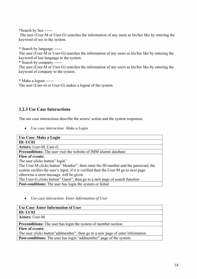
3.2.3 Use Case Interactions
The use case interactions describe the actors’ action and the system responses.
• Use case interaction: Make a Login Use Case: Make a Login ID: UC01 Actors: User-M, User-G Preconditions: The user visit the website of IMM alumni database Flow of events: The user clicks button” login” The User-M clicks button” Member”, then enter the ID number and the password, the system verifies the user’s input, if it is verified then the User-M go to next page otherwise a error message will be given The User-G clicks button” Guest”, then go to a new page of search function Post-conditions: The user has login the system or failed
• Use case interaction: Enter Information of User Use Case: Enter Information of User ID: UC02 Actors: User-M
Preconditions: The user has login the system of member section Flow of events: The user clicks button”addmember”, then go to a new page of enter information Post-conditions: The user has login “addmember” page of the system

19
• Use case interaction: Modify Information of User
Use Case: Modify Information of User ID: UC03 Actors: User-M Preconditions: The user has login the system of member section Flow of events: The user clicks button”Modify”, then go to a new page of modify information Post-conditions: The user has login “Modify” page of the system
• Use case interaction: Enter/Modify General Use Case: Enter/Modify General ID: UC04 Actors: User-M Preconditions: The user has login the system of member section, the new user clicks button”addmember” to enter his/her information, the old user clicks button”Modify” to modify his/her information Flow of events: The new user clicks tab”general”, then enters the information of general in the blank items. The old user clicks the options field of general (first name, middle name, last name, sex, citizenship, and comment) then clicks button”modify”, after that enters the new contents in the text area of “new content” item. Post-conditions: The user has entered/modified his/her information of general
• Use case interaction: Enter/Modify Education
Use Case: Enter/Modify Education ID: UC05 Actors: User-M Preconditions: The user has login the system of member section, the new user clicks button”addmember” to enter his/her information, the old user clicks button”Modify” to modify his/her information Flow of events: The new user clicks tab”education”, and then enters the information of general in the blank items. The old user clicks the options field of education (major, language, level, start time, end time, and fields of interested) then clicks button”modify”, after that enters the new contents in the text area of “new content” item Post-conditions: The user has entered/modified his/her information of education

20
• Use case interaction: Enter/Modify Contact Use Case: Enter/Modify Contact ID: UC06 Actors: User-M Preconditions: The user has login the system of member section, the new user clicks button”addmember” to enter his/her information, the old user clicks button”Modify” to modify his/her information Flow of events: The new user clicks tab”contact”, then enters the information of general in the blank items. The old user clicks the options field of education (email address, street, city, country, zip, and phone number) then clicks button”modify”, after that entera the new contents in the text area of “new content” item Post-conditions: The user has entered/modified his/her information of contact
• Use case interaction: Enter/Modify Company Use Case: Enter/Modify Company ID: UC07 Actors: User-M Preconditions: The user has login the system of member section, the new user clicks button”addmember” to enter his/her information, the old user clicks button”Modify” to modify his/her information Flow of events: The new user clicks tab”company”, then enters the information of general in the blank items. The old user clicks the options field of education (mail address, web address, name of company, users brief CV) then clicks button”modify”, after that enters the new contents in the text area of “new content” item Post-conditions: The user has entered/modified his/her information of company
• Use case interaction: Search Information Use Case: Search Information ID: UC08 Actors: User-M, User-G Preconditions: The user has login the page of search function in the system Flow of events: The user selects an option item of first name, last name, major, sex, language, and company, and then clicks it. Post-conditions: The user has selected a keyword of condition to search the information

21
• Use case interaction: Search by First Name Use Case: Search by First Name ID: UC09 Actors: User-M, User-G Preconditions: The user has selected option item of first name to search the information Flow of events: The user enters a condition of first name which is desired to search Post-conditions: The information searched by first name is displayed in the web page as a result of search or message of no result is displayed
• Use case interaction: Search by Last Name Use Case: Search by First Name ID: UC10 Actors: User-M, User-G Preconditions: The user has selected option item of last name to search the information Flow of events: The user enters a condition of last name which is desired to search Post-conditions: The information searched by last name is displayed in the web page as a result of search or message of no result is displayed
• Use case interaction: Search by Major Use Case: Search by Major ID: UC11 Actors: User-M, User-G Preconditions: The user has selected option item of major to search the information Flow of events: The user enters a condition of major which is desired to search Post-conditions: The information searched by major is displayed in the web page as a result of search or message of no result is displayed
• Use case interaction: Search by Sex Use Case: Search by Sex ID: UC12 Actors: User-M, User-G Preconditions: The user has selected option item of sex to search the information Flow of events: The user enters a condition of sex which is desired to search Post-conditions: The information searched by sex is displayed in the web page as a result of search or message of no result is displayed

22
• Use case interaction: Search by Language Use Case: Search by Language ID: UC13 Actors: User-M, User-G
Preconditions: The user has selected option item of language to search the information Flow of events: The user enters a condition of language which is desired to search Post-conditions: The information searched by language is displayed in the web page as a result of search or message of no result is displayed
• Use case interaction: Search by Company Use Case: Search by Company ID: UC14 Actors: User-M, User-G Preconditions: The user has selected option item of company to search the information Flow of events: The user enters a condition of company which is desired to search Post-conditions: The information searched by company is displayed in the web page as a result of search or message of no result is displayed
• Use case interaction: Make a Logout Use Case: Make a Logout ID: UC15 Actors: User-M, User-G Preconditions: The user has login the alumni database system Flow of events: The user clicks button” logout” Post-conditions: The user has logout the system
3.3 Non Functional Requirements Non-Functional Requirements (NFRs) of a system are attributes and characteristics of the system.Non-Functional Requirements presents a systematic and pragmatic approach to “building quality into” database system. System shall exhibit database quality attributes, such as capacity, performance, usability, security, and so on. However, such non-functional requirements are difficult to address in the project, even though there are many techniques to meet functional requirements in order to provide desired functionality.

23
3.3.1 Quality Requirements
Quality requirements specify how well the system must perform its functions. *Persistent functionality ------ The system shall allow the user to perform the functions of “switch to the homepage of IMM alumni database” and “Log of the system” anywhere in the system i.e. the functions shall always be accessible. *Capacity ------ The initial capacity of the system shall be sufficient to store all the IMM current/former students’ information of personal data, education background, and work experience at present. The system shall be scalable since the amount of students and the information of students are increasing day after day. *Performance ------ The response time for searching information in the system shall be in few seconds. The user has entered/modified his/her information, the response time for updating the information in the system shall also be in few seconds. The specified response is on the sever side alone disregarding any internet congestion as the supplier cannot be held responsible for possible internet lags. The system shall run on existing hardware which the response time mentioned above allows for. Specification for the hardware is available upon request. The system shall run fluently and no error on the data that system returned. *Usability ------- The system shall be easy to learn and use. The user should be able to use the basic features of the system without prior instruction. The user has some basic knowledge of computer and web application. The system can support the user’s tasks efficiently. The user has not to spit a task into many sub-tasks and execute those in different sections of the system in order to complete the overall task. The system shall be capable of taking over tasks on a detailed level so that the user does not to enter the information which the system is able to derive from the exiting information. *Security ------ The system shall prevent unauthorized access to programs and data. The system shall not be vulnerable to injections into the database (SQL, Xpath or the similar injections) and buffer overruns. The system is a web application system, so the system can also make countermeasures in respect of URL tampering, content suction, and script injections. *Extensibility ------ The system shall be designed and implemented in such a way that it allows for future extensions which may reasonably be expected. Extensions of the system shall be implemental without requiring a fundamental re-design of the system. *Portability ------ The system shall be easily modified to work on different platforms and environments.

24
*Maintainability ------ The system shall be easily modified and extended with new features. The system shall contain a maintenance interface which allows the administrator to modify the database design. If the modifications affect the web appearance, the respective components for the web connection have to be modified in parallel. * Testability ------ It shall be easy to verify the system meets its specifications. * Understandability ------ The design, architecture, code, and document of the system shall be easy to learn and understand. * Reliability ----- The system shall work properly and fluently without any vital errors. The system shall be stable and accomplish user’s requirements.
3.3.2 Technical Requirements
* The System ------- The System must have a server capable of the meeting the following requirements for the System's back end. The back end is where the RDBMS will live, and service all requests from the Client. * The Server Requirements ------- Intel Pentium III, 600 MHz or equivalent CPU: 256 Mb of RAM; Network Interface Card of 100Mbit/Sec; * The Operating Environment ------ Windows 2000, Windows me or Windows XP; *The Software Packages ------ The following software packages will be necessary to run the system: J2EE 1.4 SDK (Java 2 Platform, Enterprise Edition, Software Development Kit);

25
HyperText Markup Language (HTML) version 4.01; Secure Sockets Layer (SSL) version 3.0; Microsoft Access 2000. Software Development Kits *The Client Requirements ------- The client will run on any OS with a web browser. All security will be handled by the server via it's interaction with the database. The web browser must meet the following requirements: The browser must be able to parse and understand CGI forms. The browser must be able to parse and understand HTML 1.0 tags The browser must be able to understand the SSL Security implementations
3.3.3 External Interface Requirements
*User interface ------- The system shall provide an interaction of web access for the user. All the functions shall provide a graphical user interface (GUI) for the users. At all times user has a general view of the current part of system being used and where that part is placed in the navigation hierarchy. The graphical design should be professional and simple in order to prevent unnecessary absent-mindedness from the user’s tasks. The GUI shall be designed by using Java. *Hardware interface ------ The system should be usable in the screen resolution as follows: 800 x 600, 1024 x 768, and 1280 x 1024. No matter which screen resolution the user has the entire screen area can be ex exploited. *Software interface ------ The software is designed for Microsoft windows system. *Communication interface ------ The interface shall consist of respective HTML-pages. A tool has to be supplied which allows to modify the web-interface. The user can use this system through the internet.

26
3.3.4 Legal Requirements
The system shall abide by related the regulations and laws about the protection of individuals with regard to the processing of personal data. In this requirements specification a number requirements have been presented which ensure observance of the related regulations and laws. However, on the basis of the aforementioned act, it shall be determined whether further initiative is necessary in order to satisfy the requirements specified herein. The system shall be approved by DTU administration office and department of IMM at first, and then the user can use the system.
27
Chapter 4
The Overview of Database Technologies
4.1 Choosing a Relational Database Management System (RDBMS) Programming is all about data processing; data is central to everything we do with a computer. Databases—like file systems—are nothing more than specialized tools for data storage. File systems are good for storing and retrieving a single volume of information associated with a single virtual location. The data has to be stored in some organized form and we should decide on using which database technology for storing the data at first. Choosing a Relational Database Management System (RDBMS) is a mature, prevalent, theoretically well-founded and efficient way of storing structured data. In addition, data is queried by means of the standardized SQL language. SQL keywords are case-insensitive, meaning that SELECT and select are treated exactly the same. Depending on our database, however, table and column names may or may not be case-insensitive. In addition, the space between words in a SQL statement is unimportant. We can have a new line after each word, several spaces, or just a single space.
Relational database management systems (RDBMSs) are the most popular type of database in the market today. E.F. Codd at IBM established much of the theory behind relational databases in the 1970s. There is an absolute set of criteria that defines a relational database, but because no database product at this writing totally meets it, the following informal description is probably more useful:
*Data consists of records stored in tables as rows.
*Each record includes a fixed set of fields, with each field corresponding to the columns of the table.
*One column must be a primary key --- a required and unique value --- so each record can be exclusively located.
*Views --- alternate ways of looking at a table or a set of tables—must include support for inserting, updating, and deleting the appropriate data in the underlying table or tables.

28
*The database must support null an unknown value not equivalent to zero or a blank.
*A high-level relational language ---not necessarily, but usually Structured Query Language (SQL)—must be provided to support data definition, data manipulation, and database administration.
*Data constraints must be enforced by the database and cannot be bypassed.
The reasons of using a RDBMS are to control redundancy, restrict unauthorized access, provide persistent storage for program objects and data structures, permit inference and actions using rules, provide multiple user interfaces, represent complex relationships among data, enforce integrity constraints and provide backup and recovery. A RDBMS is well studied and well understood. There are many hundreds of RDBMSs on the market such as MS Access, MS SQL sever, Informix, Oracle, DB2, SQLite, Sybase, dBase, Postgre SQL, MySQL, FOXPRO, PARADOX, ADABASE, mSQL and so on. The factors for choosing a RDBMS are platform and system, support data types, application function, program language supporting, analysis ability, ease of use and documentation, performance and internet ability. We only consider some of the most widely used RDBMSs to compare. Each of them has its own advantages and disadvantages. Now we introduce the Microsoft Access which is used by us in the project as below:
4.1.1 Microsoft Access (MS Access)
MS Access can be used on one computer or as a multi-user system on a computer network. There is a choice of two data engines in the product: the original Jet engine and the new Microsoft Data Engine (MSDE), which is compatible with Microsoft’s back-office SQL Sever. The Jet engine stores all the application dada such as tables, indexes, queries, forms and reports in a single Microsoft database (.mdb) file, based on Indexed Sequential Access Method (ISAM) organization. MSDE is based on the same data engine as SQL Sever; it also offers a migration path to allow users to subsequently upgrade to SQL Sever. MS Access, similar with SQL Sever, divides the data stored in its table structures into 2 kilo-byte data pages, corresponding to the size of a conventional DOS fixed-disk file cluster. Each page contains one or more records. A record can’t span more than a single page, although Memo and OLE Object fields can be stored in pages separate form the rest of the record. MS Access uses variable-length records as the standard method of storage and allows records to be ordered by the use of an index such as primary key. Each record occupies only the space required to store its actual data by using the variable length. A header is added to each page to make linked lists of data pages. There exists a pointer in a header to the page which precedes it and another pointer to the page that follows. If there is no index in

29
use, then new data can be added to the last page of the table until the page is full, and then another page can be added at the end. One advantage of data pages with their own header is that a table’s data pages can be kept in ISAM order by altering the pointers in the page header, and not the structure of the file itself. MS Access contains a Graphical User Interface (GUI) to make tables, queries, forms, and reports, and tools to develop customized database applications using the MS Access macro language or the Microsoft Visual Basic for Applications (VBA) language. MS Access contains programs which are called Wizards to simplify many of the progresses of creating a database application by taking the user through a series of question-and-answer dialog boxes. It also contains Builders to help the user build syntactically correct expressions, such as those required in SQL statements and macros. MS Access supports much of the SQL standard and the Microsoft Open Database Connectivity (ODBC) standard, which offers a common interface for accessing heterogeneous SQL databases. MS Access provides a set of objects described as below for user to develop a database application. * Table ------ The table is organized into columns (or called fields) and rows (or called records). The base tables make up the database. * Query ------ Query allows the user to view, change, and analyze data in different ways. Queries can also be stored and used as the sources of records for forms, reports, and data access pages. *Form ------ Form can be used for a variety of purposes such as to create a data entry form to enter data into a table. * Report ------ Report allows data in the database to be presented in effective way in a customized printed format. * Page ------ A (data access) page is a special type of Web page designed for viewing and working with data (stored in a Microsoft Access database or a Microsoft SQL Server database) from the Internet or an Intranet. The data access page may also include data from other sources, such as Microsoft Excel.

30
* Macro ------ Macro is a set of one or more actions that each performs a particular operation, such as opening a form or printing a report. Macros can help automate common tasks such as printing a report when a user clicks a button. * Modules ------ Module is a collection of VBA declarations and procedures that are stored together as a unit. The following figure (Figure 4-1) shows the access database design template.
Figure 4-1: Access database
There are four main ways of working with a database is shared among users on a network by using MS Access. * File-server solution ------ The multiple users can share the MS Access database for MS Access can be installed in a computer network system, and each workstation runs a copy of the Access application.

31
* Client-sever solution ------ An MS Access project file (.adp) can be created, which can store forms, reports, macros, and VBA modules locally and can connect to a remote SQL Sever database using Object Linking and embedding for databases (OLE DB) to display and work with tables, views, relationships, and stored problems. MSDE can also achieve this type of solution as above mentioned. * Database replication solution ------ Data replication solution allows the data or database design changes to be shared between copies of an MS Access database in different locations without having to re-distribute copies of the whole database system. The replication of database involves generating one or more copies called replicas, of a single original database, called the design master, and the design master and replicas are called a replica set with together. There are some changes to object and data are distributed to all members of the replica set by performing a process which is named synchronization. The changes to design of objects can only be made in the design master, but the changes to data can me made from any member of the replica set. * Web-based database solution ------ A browser displays one or more data access pages which dynamically link to a shared MS Access or SQL Sever database. These pages have to be the displayed by browser of Internet Explore or Netscape in high versions. When a database locates on a file sever, the opening system’s locking primitives are used a locking database (.ldb) file to store information on which records are locked and which user has them locked. The locking database file is created when a database is opened for shared access.
4.1.2 Oracle
To develop a large RDBMS, there are numerous good reasons to choose Oracle over its competitors in the RDBMS market. Here we give a brief description of Oracle for the future development. The Oracle Corporation is the world's leading supplier of software for information management, and the world's second largest independent software company. Oracle database technology is widely used in large database system of enterprises. The developer develops an Oracle database system by using a set of objects in oracle like MS Access. The main objects in Oracle are table, object, cluster; indexes, synonyms, functions/procedures, packages and triggers. The architecture of Oracle is based on client-sever. The Oracle server consists of the database (the raw data, including log and control files) and the instance (the processes and system memory on the server that provide access to the database). An instance can connect to only one database. The

32
database consists of a logical structure, such as the database schema, and a physical structure, containing the files that make up an Oracle database. Another good reason for choosing Oracle is it has nice cooperation with Java.
• We can use Java and SQLJ (with embedded SQL statements) outside the Oracle database. • We can use Java and Java database connectivity (JDBC) outside the Oracle database. • We can use Java inside the database as stored procedures. • We can use a middleware layer to manage the connection between Java and the database.
4.1.3 MySQL
MySQL is another frequently used RDBMS today. The strongpoint of MySQL is that it is an Open Source Standard Query Language database. It is fast, reliable, easy to use, and suitable for applications of any size. MySQL can easily be integrated into Perl programs by using the Perl DBI (DataBase Independent interface) module. DBI is an Application Program Interface (API) that allows Perl to connect to and query a number of SQL databases.
4.2 Java Technology and JDBC API Java is a simple, object-oriented, distributed, interpreted, robust, secure, architecture-neutral, portable, high-performance, multi-threaded, and dynamic language from Sun Microsystems. Java applications are compiled into byte codes, which are interpreted and executed by the Java Virtual Machine. By introducing virtual machine concept,
Java code has become completely portable. For this reason Java is very suitable for applications executed on different platforms (computer systems), and became very popular in web- and internet-based applications. Java can be connected to an ODBC-compliant RDBMS through, among other mechanisms, JDBC or SQLJ.
The first standardized work on Java-DBMS connectivity appears in a draft specification known as the Java Database Connectivity (JDBC) Application Programming Interface (API) specification. Created with the help of the database and database-tool vendors, it is intended to fill the current vacancy in this level of connectivity that has prompted companies like Web logic to develop proprietary interfaces.
The fundamental technology linking Java and databases is Java database connectivity. The JDBC specification defines a way to access any form of tabular data from Java—from text files to spreadsheets to databases. Java provides a set of interfaces in the core language, the java.sql package. The database vendor typically provides an actual implementation in the form of a JDBC

33
driver. After loading the driver in our code, we can connect to the database, send SQL statements to the database, and retrieve results.
The following figure illustrates the relationship between JDBC and database.
Figure 4-2: JDBC and Database
JDBC is in a SQL-level API that allows us to embed SQL statements as arguments to methods in JDBC interfaces. To enable us to do this in a database-independent fashion, JDBC requires database vendor to furnish a runtime implementation of its interfaces. These implementations route our SQL calls to the database in the proprietary fashion it recognizes. As the programmer, though, we do not ever have to worry about how it is routing SQL statements. The façade provided by JDBC gives us complete freedom from any issues related to particular database issues; we can run the same code no matter what database is present.
JDBC creates a programming-level interface for communicating with databases in a uniform manner similar in concept to Microsoft's Open Database Connectivity (ODBC) component which has become the standard for personal computers and LANs. The JDBC standard itself is based on the X/Open SQL Call Level Interface, the same basis as that of ODBC. This is one of the reasons why the initial development of JDBC is progressing so fast.
Object classes for opening transactions with these databases are written completely in Java to allow much closer interaction than we would get by embedding C language function calls in Java programs, as we would have to do with ODBC. This way we can still maintain the security, the robustness, and the portability that make Java so exciting.

34
The figure shown as below illustrates the JDBC and ODBC Bridge.
Figure 4-3: JDBC and ODBC
35
JDBC consists of two main layers: the JDBC API supports application-to-JDBC Manager Communications; the JDBC Driver API supports JDBC Manager-to-Driver implementation communications. The Manager handles communications with multiple drivers of different types from direct-interface implementations in Java to network drivers and ODBC-based drivers.
In terms of Java classes, the JDBC API consists of:
* java.sql.Environment - allows the creation of new database connections;
*java.sql.Connection - connection-specific data structures;
*java.sql.Statement - container class for embedded SQL statements;
*java.sql.ResultSet - access control to results of a statement.
The JDBC Driver API is contained in java.sql.Driver. Each driver must provide class implementations of the following virtual classes: java.sql.Connection, java.sql.Statement, java.sql.PreparedStatement, java.sql.CallableStatement, and java.sql.ResultSet. These virtual classes describe the API but are specific to how each database functions. The JDBC-ODBC Bridge performs translations of JDBC calls to that which can be understood by ODBC clients at a C language level. This bridge is quite small due to the similarities of the specifications. The bridge is needed to isolate native C language calls to a controlled area while maintaining compatibility with non-JDBC databases.
SQLJ is another JDBC-based approach uses Java with embedded SQL. It is the easiest way to perform database access from Java. It is an ANSI standard way of embedding static SQL statements in Java code. A pre-compiler is used to translate the SQLJ and Java code into a pure Java source file. In the case of SQLJ implementation, at least, the underlying connectivity is actually achieved with JDBC, and it is possible to mix SQLJ code with JDBC.

36

37
Chapter 5
System Design and Implementation This chapter describes the architecture and the technologies applied on a generic database system of IMM alumni net. Based on ER model and requirements specification of the system, we design and implement an alumni database system. We present the detailed procedures of design and implementation in this chapter.
5.1 System Architecture With the arrival of the web, 3-Tier architecture has come to dominate new applications. The alumni database system is basically a 3-Tier architecture. 3-tier architecture is aimed to solve some of problems about traditional client/server application, now it has dominated the web applications. It consists of the following three parts: *User Interface Tier (or called Client Tier) --- which delivers the application to the end users on the Web. *Application-Logic Tier (or called Service/Server Tier) --- which contains and executes the rules that run the application. *Database Tier (or called Case Base Tier) --- which manages the data required by the application. The application-logic tier is the middleman between the user interface tier and the database tier. When a user performs a task, his/her request first goes to the web server, residing on the first tier. The web server directs the request to the application server on the second tier, to be processed. In processing the request, the application server may query data from the database tier. The processed request is returned to the first level, the web server, where the processed information is encoded into HTML, the language of the web, and sent back over the internet to the user’s browser. The following figure illustrates the 3-Tier architecture (Figure 5-1).

38
Figure 5-1: 3-Tier Architecture
A 3-Tier architecture is considered to be the most suitable architecture for web-base applications. The partitioning of the application enables rapid design and development of the system. The modularity makes it easier to make changes to just one tier without affecting the others. Separating the functions into distinct tiers makes it easier to monitor and optimize the performance of each tier. Load balancing and adding more capacity can take place independently at each tier. Multi-tier architecture also makes it simpler to scale the system across multiple processors on different machines.3-Tier architecture can provides better security by enabling more fine-grained authorization on the sever and not exposing the database schema to the client.
5.2 Web Site Implementation We use the homepage of IMM department as the template to build our user interface. We delete some useless links and change the Student info icon to our Alumni Database icon.
Page1.html <TR> <TD align=right height=19><A class=main href="C:/Applet/page2.html">Alumni Database <IMG height=11 src="Informatics and Mathematical Modelling, DTU_files/student.gif" width=11 align=absMiddle border=0></A></TD></TR>
Code-Box (5-1): Page1.html
39
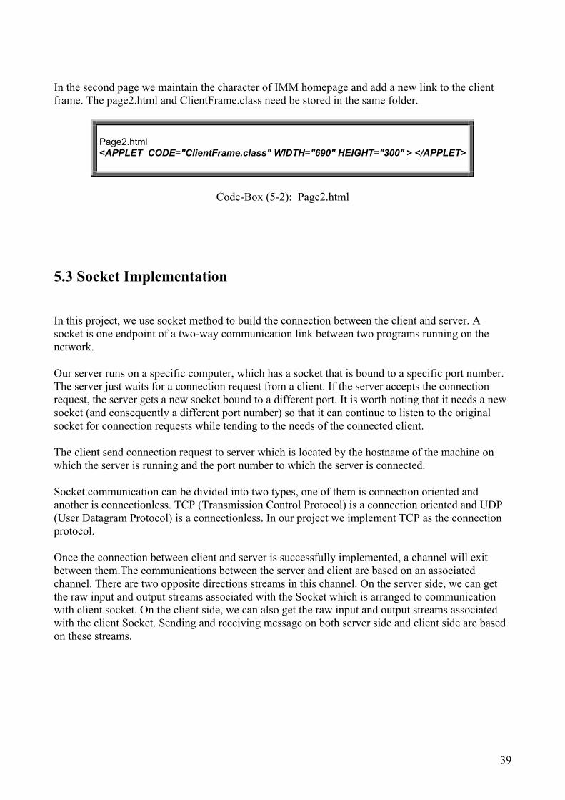
In the second page we maintain the character of IMM homepage and add a new link to the client frame. The page2.html and ClientFrame.class need be stored in the same folder.
Page2.html <APPLET CODE="ClientFrame.class" WIDTH="690" HEIGHT="300" > </APPLET>
Code-Box (5-2): Page2.html
5.3 Socket Implementation In this project, we use socket method to build the connection between the client and server. A socket is one endpoint of a two-way communication link between two programs running on the network.
Our server runs on a specific computer, which has a socket that is bound to a specific port number. The server just waits for a connection request from a client. If the server accepts the connection request, the server gets a new socket bound to a different port. It is worth noting that it needs a new socket (and consequently a different port number) so that it can continue to listen to the original socket for connection requests while tending to the needs of the connected client.
The client send connection request to server which is located by the hostname of the machine on which the server is running and the port number to which the server is connected.
Socket communication can be divided into two types, one of them is connection oriented and another is connectionless. TCP (Transmission Control Protocol) is a connection oriented and UDP (User Datagram Protocol) is a connectionless. In our project we implement TCP as the connection protocol. Once the connection between client and server is successfully implemented, a channel will exit between them.The communications between the server and client are based on an associated channel. There are two opposite directions streams in this channel. On the server side, we can get the raw input and output streams associated with the Socket which is arranged to communication with client socket. On the client side, we can also get the raw input and output streams associated with the client Socket. Sending and receiving message on both server side and client side are based on these streams.

40
This process can be shown by the following figure (Figure 5-2).
Figure 5-2: Socket
5.3.1 On the Server-side:
In our project, we implement server side as the following program :
41
public class Servant extends Thread ServerSocket s = new ServerSocket(9999); for (;;) { Socket incoming =s.accept(); HandlrequestL handle=new HandlrequestL(incoming, i); handle.start(); i++;} class HandlrequestL extends Thread public HandlrequestL(Socket incoming, int u) out=new ObjectOutputStream(incoming.getOutputStream()); in=new ObjectInputStream(incoming.getInputStream());
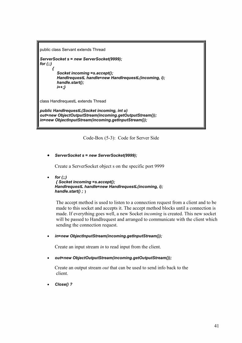
Code-Box (5-3): Code for Server Side
• ServerSocket s = new ServerSocket(9999); Create a ServerSocket object s on the specific port 9999
• for (;;)
{ Socket incoming =s.accept(); HandlrequestL handle=new HandlrequestL(incoming, i); handle.start() ; }
The accept method is used to listen to a connection request from a client and to be made to this socket and accepts it. The accept method blocks until a connection is made. If everything goes well, a new Socket incoming is created. This new socket will be passed to Handlrequest and arranged to communicate with the client which sending the connection request.
• in=new ObjectInputStream(incoming.getInputStream()); Create an input stream in to read input from the client. • out=new ObjectOutputStream(incoming.getOutputStream());
Create an output stream out that can be used to send info back to the
client. • Close() ?

42
Because our system is a web-based database, the server side needs to wait for the client’ request all day and all night. We think it is not necessary to design the close() function for the server side.
5.3.2 On the Client-side:
In our project, we implement client side as the followings:
public class ClientFrame extends JApplet implements ActionListener if (!logedOn) try {s=new Socket("127.0.0.1",9999); out = new ObjectOutputStream(s.getOutputStream()); in = new ObjectInputStream(s.getInputStream()); if (str.equals("Logout")) { out.writeObject("BYE"); second.setVisible(false); first.setVisible(true); setContentPane(first);
repaint(); s.close(); logedOn=false;}
Code-Box (5-4): Code for Client Side
• s=new Socket("127.0.0.1",9999);
The constructor Socket ("127.0.0.1",9999) just creates a stream socket and connects it to the specified port number 9999 at the specified IP address 127.0.0.1. If we run this system on single machine, we can use the default IP address 127.0.0.1 as the hostname of the server. If we test this system in more than one computer, please replace this value by the server’s IP address.
• out = new ObjectOutputStream(s.getOutputStream());
Create an output stream out that can be used to send info to the Socket.
• in = new ObjectInputStream(s.getInputStream()); Create an input stream to read the response from the server.
• s.close();

43
Close the socket when done.
5.3.3 Thread Method
In order to allow our server handle multi-clients at the same time .We extend the thread method to server. The multithreaded server program is able to create a new thread for every client request. Thus, each client has its own connection to the server for communication. Based on this idea, the multithreaded server program is implemented by the following:
Code Box (5-5): Code for Thread
In the loop body, accept method is called to wait for client connections and create a socket. The instance handle of class HandlrequestL is created to the communication between the socket and client socket.
for (;;) {}
We can see that the loop will be unlimited, so that server can be continually listen to the request of client.
5.4 Access Database Design and Implementation
public class Servant extends Thread ServerSocket s = new ServerSocket(9999); for (;;) { Socket incoming =s.accept(); HandlrequestL handle=new HandlrequestL(incoming, i); handle.start(); i++;}

44
We start to design a database by analyzing all of information which database must hold and the relationships among the information. The following figure (Figure 5-3) illustrates the procedure of database design and implementation.
Figure 5-3: Database Modelling
Microsoft Access database is a good tool to build relational database. We use it as our database server. A relationship exists between two tables when one or more key fields from one table are matched to one or more key fields in another table. This database is a relational database and it

45
includes two tables and one form. Table Key is used to store the Student ID and Password. See the Figure 5-4.
Figure 5-4: Key Table
Table Student saves the information of the members. See the Figure 5-5.
Figure 5-5: Student Table
We make Student ID as the primary key of these two tables. It also builds a relationship between these two tables. The reasons that why I choose Student ID as primary key are the followings:
Every former or current student of IMM has his/her own Student ID.
To IMM students, the Student ID is used frequently during their study life. So it is not difficult to keep it in mind.
The Student ID is very stable. It means that the student ID is hardly changed by the
government.

46
If some guys have more one Student ID, they can apply for opening several accounts in
the database corresponding to their different IDs.
The Student-form is a tabbed form of Table Student. The information of Table Student is displayed in 4 paginations named General, Education, Company and Contact. It is helpful for the administrator to find out the interested information directly. See the Figure 5-6.
Figure 5-6: Student Form
5.5 JDBC Design and Implementation JDBC (Java Database Connectivity) is set of Java API's that enables the developers to create platform and database independent applications in java. The JDBC API makes it easy to send SQL

47
statements to relational database systems and supports all dialects of SQL. The biggest advantage programming in Java is that one doesn't have to worry about writing different applications to run on different platforms. The combination of the Java platform and the JDBC API lets a programmer write once and run anywhere. We know that Sun defined four JDBC driver types. These are:
• Type 1: JDBC-ODBC Bridge Driver --- The JDBC-ODBC Bridge provides JDBC access to any ODBC complaint databases through ODBC drivers.
• Type 2: Native -API Partly - Java Driver ---
Type 2 drivers are developed using native code libraries, which were originally designed for accessing the database through C/C++.
• Type 3: JDBC-Net Pure Java Driver ---
Type 3 drivers are a three-tier solutions. This type of driver communicates to a middleware component which in turn connects to database and provide database connectivity.
• Type 4: Native-Protocol Pure Java Driver ---
The last drivers are entirely written in Java that communicate directly with vendor's database through socket connection.
In our project, we choose the type one as our JDBC driver. We implement the insert f( Enter information ), update ( Modify information ) and select (Search information) SQL functions in this project.
5.5.1 Connect to Database
class HandlrequestL extends Thread public void DBconnect() throws java.sql.SQLException { System.out.println( "\nDatabase Connecting – Please Wait....\n"); try{ Class.forName("sun.jdbc.odbc.JdbcOdbcDriver"); con = DriverManager.getConnection( "jdbc:odbc:DRIVER={Microsoft Access . Driver (*.mdb)};DBQ=H:\\private\\db\\db1.mdb" ); } catch(java.sql.SQLException e1){System.out.println(e1);} catch(java.lang.ClassNotFoundException e) {} System.out.println( "\nDatabase is Connected \n"); }

48
Code-Box (5-6): JDBC Connect
• Class.forName("sun.jdbc.odbc.JdbcOdbcDriver"); Load the JDBC driver for our database
• con = DriverManager.getConnection( "jdbc:odbc:DRIVER={Microsoft Access Driver (*.mdb)};DBQ=H:\\private\\db\\db1.mdb" );
Connect to the database. DBQ=H:\\private\\db\\db1.mdb is the directory of the database. If the login name and password were set in Access Database, they also need be declared in this section.
• System.out.println( "\nDatabase Connecting – Please Wait....\n"); System.out.println( "\nDatabase is Connected \n");
If everything goes well, we can see these connection messages on the monitor of server side.
5.5.2 Enter Information (Insert)
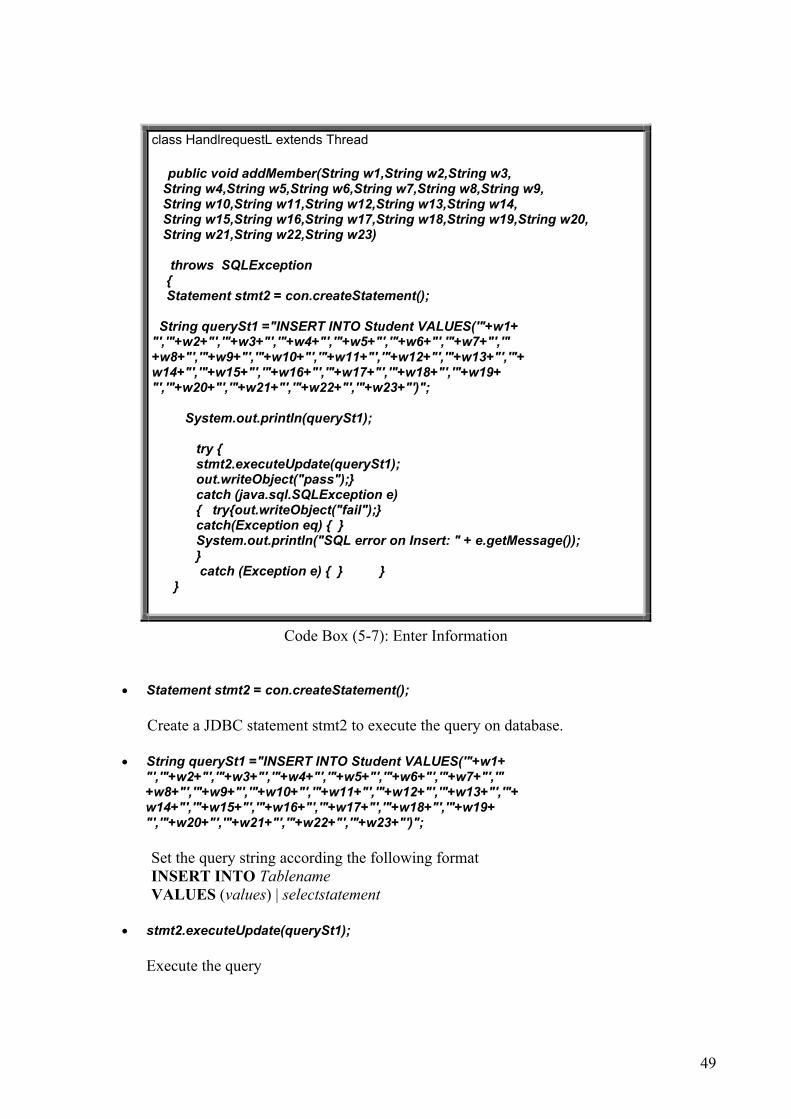
49
Code Box (5-7): Enter Information
• Statement stmt2 = con.createStatement(); Create a JDBC statement stmt2 to execute the query on database.
• String querySt1 ="INSERT INTO Student VALUES('"+w1+ "','"+w2+"','"+w3+"','"+w4+"','"+w5+"','"+w6+"','"+w7+"','" +w8+"','"+w9+"','"+w10+"','"+w11+"','"+w12+"','"+w13+"','"+ w14+"','"+w15+"','"+w16+"','"+w17+"','"+w18+"','"+w19+ "','"+w20+"','"+w21+"','"+w22+"','"+w23+"')"; Set the query string according the following format INSERT INTO Tablename VALUES (values) | selectstatement
• stmt2.executeUpdate(querySt1);
Execute the query
class HandlrequestL extends Thread public void addMember(String w1,String w2,String w3, String w4,String w5,String w6,String w7,String w8,String w9, String w10,String w11,String w12,String w13,String w14, String w15,String w16,String w17,String w18,String w19,String w20, String w21,String w22,String w23) throws SQLException { Statement stmt2 = con.createStatement(); String querySt1 ="INSERT INTO Student VALUES('"+w1+ "','"+w2+"','"+w3+"','"+w4+"','"+w5+"','"+w6+"','"+w7+"','" +w8+"','"+w9+"','"+w10+"','"+w11+"','"+w12+"','"+w13+"','"+ w14+"','"+w15+"','"+w16+"','"+w17+"','"+w18+"','"+w19+ "','"+w20+"','"+w21+"','"+w22+"','"+w23+"')"; System.out.println(querySt1); try { stmt2.executeUpdate(querySt1); out.writeObject("pass");} catch (java.sql.SQLException e) { try{out.writeObject("fail");} catch(Exception eq) { } System.out.println("SQL error on Insert: " + e.getMessage()); } catch (Exception e) { } } }

50
5.5.3 Modify Information (Update)
Code Box (5-8): Modify information
• Statement stmtm = con.createStatement(); Create a JDBC statement stmtm to execute the query on database.
• querym ="UPDATE Student SET "+wm2+"= '"+wm3+"' WHERE StudentID= "+"'"+wm1+"'";
Set the query string according the following format UPDATE Tablename SET columnname=expression, ...
[WHERE searchcondition(s)]
• stmtm.execute(querym);
Execute the query
5.5.4 Search Information (Select)
class HandlrequestL extends Thread public void modify(String wm1,String wm2,String wm3) throws java.sql.SQLException { String querym=""; Statement stmtm = con.createStatement(); querym ="UPDATE Student SET "+wm2+"= '"+wm3+"' WHERE StudentID= "+"'"+wm1+"'"; System.out.println(querym); stmtm.execute(querym); }

51
Code Box (5-9): Search information
• Statement stmt = con.createStatement(); Create a JDBC statement stmt
• query ="SELECT StudentID,FirstName,LastName,MiddleName,Citizenship,Sex,Comments,
Tel,Email,Country,City,Major,StartDate,Language,Company,CAddress, CLink,CV FROM Student WHERE "+ s1+"="+"'"+s2+"'" ; Set the query string according the following format SELECT selectlist [INTO new_table] FROM tablename [WHERE searchcondition(s)]
• ResultSet rs = stmt.executeQuery(query);
Execute the query and return the result to ResultSet rs.
5.5.5 Disconnect to Database
class HandlrequestL extends Thread public void DBdisconnect() throws java.sql.SQLException { System.out.println( "\n Database Disconnecting - Please Wait....\n"); con.close();
class HandlrequestL extends Thread Statement stmt = con.createStatement(); StringBuffer supName1=new StringBuffer(); query ="SELECT StudentID,FirstName,LastName,MiddleName,Citizenship,Sex,Comments, Tel,Email,Country,City,Major,StartDate,Language,Company,CAddress, CLink,CV FROM Student WHERE "+ s1+"="+"'"+s2+"'" ; ResultSet rs = stmt.executeQuery(query); System.out.println(query);

52
System.out.println( "\nThe Connection is closed\n");
Code Box (5-10): Disconnect to database
• con.close();
It is clear that it closes the connection to the database.
5.6 Key Functions Implementation
In our design, at first the user logs in the system and then goes to the main frame of IMM database home page. In the main frame, the user has four choices: Guest, Member, Logout and Help. Help function is to get the help instruments and user manual of the system. When user clicks the button ”help”, a text page of help instruments and user manual will jump out. User can read it to know how to use the functions of this system. If user is a guest of the system, he/she should click button ”Guest” and then go to search function to search his/her desired information in the database, after search he/she can log out the system. If user is a member who has got the member ID and password from the DTU administration office of the system, he/she should click button “Member” and then he/she enters the member ID and password. If the system has authenticated member ID and password, the user can go to the member frame; otherwise it is jumped out to the main frame. In the member frame, the member has three choices of the functions. One is the enter function; the new user who has empty information in the database clicks button ”enter” to enter all of his/her information into the database. One is modify information; the old user who has his/her information stored in the database clicks button ”modify” to modify his/her information which he/she want to modify in the database. The last one is exit, the member clicks button ”exit” to exit to main frame. The logout function allows user to logout the system. In the following figure (Figure 5- 7), you can get the flow chart of the key functions in this project.

53
Figure 5-7: Flow chart The socket communication between server and client are all based on a set of protocols. We would like to present these protocols in details in following sections.
54
5.6.1 Search Function
All guests and members can execute this search function to get their interested information. To be convenient for users, we implement a GUI for this function. The operations of search function are shown as following steps:
• Choose one key word from the Key word list • Fill in the search condition in the Condition field • Press the search results button to submit your requirement • Get the results in the received message window. • If the use does some error operation, he/she would get the help information in the received
message window.
We collect 23 kinds of personal information in our database, but we only take 6 of them as the search key word. The reasons that we set these option fields as our keywords of search functions are:
• First Name or Last Name ------ For searching a person, we normally know his/her first name or last name. And the first name and last name is a stable character of person. It is the easiest way to search the corresponding information. Maybe we know the first name or last name; maybe we know both of them. We don’t consider middle name as the keyword for most of person don’t have such a middle name.
• Sex ( Gender )------ Sex is a very obvious and important attribute of a person. Normally, there are two kinds of gender for a person: Male of Female. Some companies may have the requirement of gender for their job career. Using this keyword is easy to find the persons whom they need.
• Language ------ IMM is an international education institution. Its’ personnel comes from several countries. Some IMM students are taking the Danish line, some IMM students are taking the English line, and other are taking the education program in the specific languages. Some companies may have the requirement of language for their job career. Use the keyword of language is easy to find the persons whom they need. Some people may want to communicate with the persons who use the same language as them, so use keyword of language is a good way for searching.

55
• Major ------ Major is the most important and obvious title of person’s education. If the company wants to recruit the employee, the first interested thing is the major of the candidate. If the IMM students want to communicate and discuss the things of academic, they care about the person’s major. So the keyword of major is ideal way of searching desired persons.
• Company ------
The IMM students are very interested in which companies the IMM alumni are working in currently. Maybe they can do the comparisons for the plans of personal career. The information of company is an important reference for the development of IMM student’s personal career.
After discussing the chosen searching keywords, let’s see how the searching function implements. If all necessary information is filled, the user can click the “searchal”l button. The string that starts with “searchall” with search condition will be sent to server, when server receives the string and makes sure the string that starts with the key word “searchall”, it will call the method search. The search result will be got from this method. If server successfully gets the matched information, the server will return this information to client. Client side will display detail information to the user on the searching result window. The process can be shown in the flow figure:

56
Fill in the request in Search GUI
Click Button Search results
Handle button event
Stream Channel
Write message"searchall"+","+
keyword+","+condition
to stream channel
If the message strats with ”searchall”
Read message
from channel
yes
access database Serach all
informations which matched condition
DatabseTable :Student
Wrirte matched
informationsto channel
Read search result from
channel
The flow chart of search operation
Figure 5-8: Flow chart: Search
5.6.2 Check ID and Password
If one former or current student of IMM wants to add his/her information into this database, he/she must get a legal password. The following section shows the procedure of applying for a password.

57
Figure 5-9: Check ID and Password
Application process:
• Step 1: The applicants should provide their certificated document (including their Student ID) to DTU Student Office.
• Step 2: The DTU Student Office should check up the applicants’ documents. If the
applicants fix in with the requirement, the DTU office need inform the IMM Database administrator to add new space in the Database.
• Step 3: The IMM Database administrator should fill in a pair of Student ID and Password in
Key Table. • Step 4: The IMM Database administrator returns the acceptance information of ID and
Password to DTU Student Office. • Step 5: The DTU Office sends the Login Name (Student ID), Password and User Manual to
the applicants

58
• Step 6: Now the applicant can login this database as a new member with his/her Login name and Password.
First the user inputs his/her ID and Password in the blank boxes and then click button ok, the string which starts with “check” will be sent to server, when server receives the string and makes sure the string starts with the key word “check”, it will call the method check. The check result will be got from this method. If the result of checking is true, then server return a key word “pass” to client, otherwise return a key word “fail”. Client side will display detail information to the user about checking result The entire process is shown in the flow chat as below.
Figure 5-9: Flow chart Check
5.6.3 Enter Information Function

59
If a member passed the check function and login the database, this member need enter the information into the database. The user needs to fill in all blanks and then click button OK. A string “addmember” will be sent to sever side. And the server will check the input information to see if it was a legal message. If all operations are correct, the new information would be inset into database. Otherwise, an error message will appear. And the according “pass” or “fail” key words would be returned to client. The entire process is shown in the flow chat (Figure 5-10).
Figure 5-10: Flow chart Enter

60
5.6.4 Modify Information Function
The above enter information function only can enter information to an empty table and can not rewrite the information. So if the members want to change their information, they must run this Modify Information function. First the user should choose one optional filed and input the changed information. And then click button Modify, the string that starts with “modify” will be sent to server, when server receives the string and make sure the string starts with the key word “modify”, it will call the method Modify. The modify method will change the corresponding component in student table to the new value. The entire process is shown in the below figure.
Figure 5-11: Flow chart Modify

61
We evaluate every element of the database with an index. And this index assures that the corresponding entity in the database will be modified. But the members do not have the power to modify all information. For example, the members can not change their ID. The reason is that we use Student ID as the primary key of this database. Any changing of Student ID might bring fatal mistake to the system.
5.7 Installation Guide to Administrator of IMM Alumni Database After the design and the implementation of system, we generate a software package of this project. We give the installation guide to administrator of IMM Alumni Database as below.
5.7.1 Installation Requirements
Hardware requirements:
Intel Pentium III, 600 MHz or equivalent CPU: 256 Mb of RAM; Network Interface Card of 100Mbit/Sec.
Software requirements:
J2EE 1.4 SDK (Java 2 Platform, Enterprise Edition, Software Development Kit); HyperText Markup Language (HTML) version 4.01; Secure Sockets Layer (SSL) version 3.0; Microsoft Access 2000; Java Virtual Machine
5.7.2 The Components of System
In this project we design two versions of the DBMS finally. The applet version produces a ClientFrame applet and it can be inserted into any web-page easily. The application version has favorable socket communication and web security. The java codes of these two versions are almost same. The only difference is applet version extends Japplet and the application version extends Jframe.

62
1. Access Database
a. Two Tables : Key : To save the Student ID and Password Student : To save the information of members
b. One Form StudentForm : The form of the Table Student
2. Java Program
Applet Version:
a. Server Side : Newserver.java : The main function of Server Servant.java : To set the number of the ServerSorket HandlrequestL.java : To handle the requests gotten through the port.
b. Client Side :
ClienFrame : It is a Java-Applet program and produces a class file named ClientFrame.class. It could be executed by a Web-page to transfer the request of Client to Server.
Conpanel.class, Companel.class, Edupanel.class and Gerneralpanel.class are used to build the tabbed panel for new members to enter their information into Database.
c. The Web-page part :
Page1.html : It is a IMM homepage like file. Page2.html : It has a link to Clientframe.class
Two DTU_file folders : They are used to save the pic and JScript files of the web-page.
• Application version
a. Server Side : Newserver.java : The main function of Server Servant.java : To set the number of the ServerSorket HandlrequestL.java : To handle the requests gotten through the port. b. Client Side :
Mainwindow : The main function of Client side. ClienFrame : It is a Java-Application program. It is used to handle the requirement
between server and client.
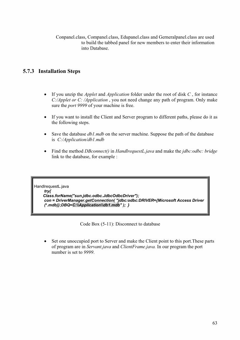
63
Conpanel.class, Companel.class, Edupanel.class and Gerneralpanel.class are used to build the tabbed panel for new members to enter their information into Database.
5.7.3 Installation Steps
• If you unzip the Applet and Application folder under the root of disk C , for instance C:/Applet or C: /Application , you not need change any path of program. Only make sure the port 9999 of your machine is free.
• If you want to install the Client and Server program to different paths, please do it as
the following steps.
• Save the database db1.mdb on the server machine. Suppose the path of the database is C:/Application/db1.mdb
• Find the method DBconnect() in HandlrequestL.java and make the jdbc:odbc: bridge
link to the database, for example :
HandlrequestL.java
try{ Class.forName("sun.jdbc.odbc.JdbcOdbcDriver"); con = DriverManager.getConnection( "jdbc:odbc:DRIVER={Microsoft Access Driver
(*.mdb)};DBQ=C:\\Application\\db1.mdb" ); }
Code Box (5-11): Disconnect to database
• Set one unoccupied port to Server and make the Client point to this port.These parts of program are in Servant.java and ClientFrame.java. In our program the port number is set to 9999.
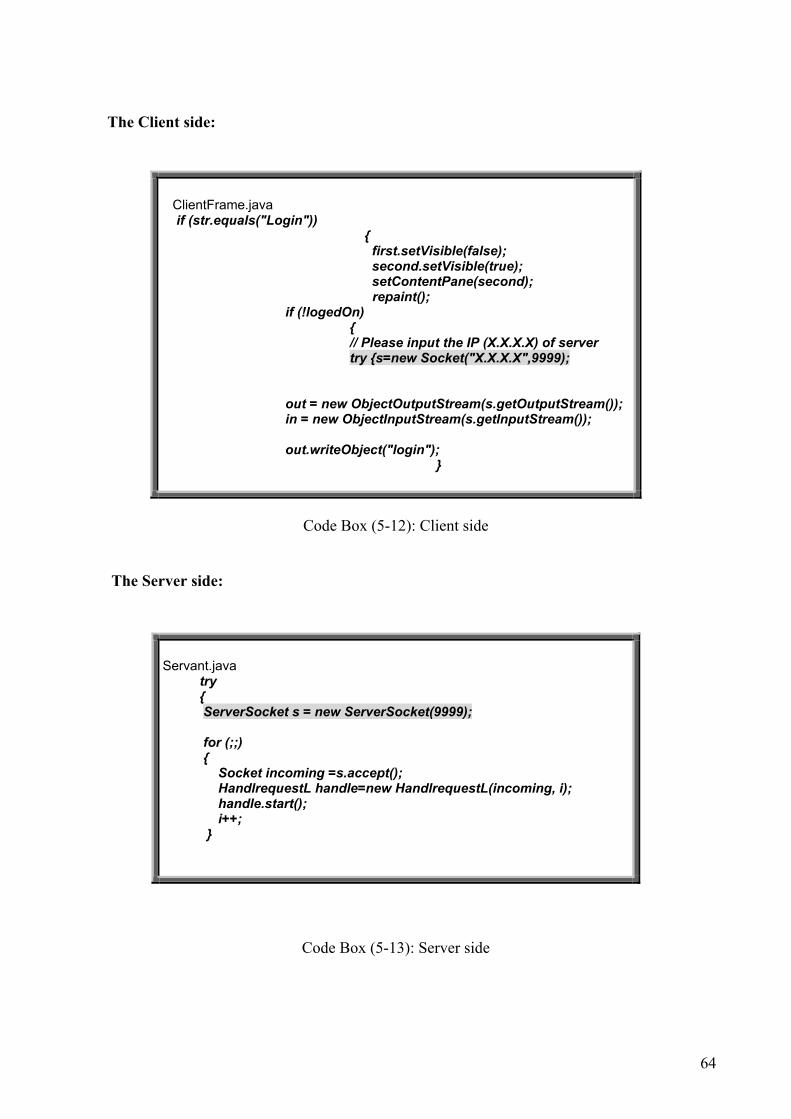
64
The Client side:
Code Box (5-12): Client side
The Server side:
Code Box (5-13): Server side
ClientFrame.java if (str.equals("Login")) { first.setVisible(false); second.setVisible(true); setContentPane(second); repaint(); if (!logedOn) { // Please input the IP (X.X.X.X) of server try {s=new Socket("X.X.X.X",9999); out = new ObjectOutputStream(s.getOutputStream()); in = new ObjectInputStream(s.getInputStream()); out.writeObject("login"); }
Servant.java try { ServerSocket s = new ServerSocket(9999); for (;;) { Socket incoming =s.accept(); HandlrequestL handle=new HandlrequestL(incoming, i); handle.start(); i++; }

65
5.7.4 Implementation:
• Application Version
Execute newserver.java to open the socket of Server side. Execute mainwindow.java to open the socket of Client side.
• Applet Version Save the web-page files and ClientFrame.java in the same folder.
Execute newserver.java to open the socket of Server side. Execute page1.html to open the socket of Client side.
Hints: Your computer should accept Applet program as trusted applet.

66
67
Chapter 6
Test of the system
In order to assure the modules or system works as the requirements we make the tests for all the functions and the entire system. Our test focuses on making sure that all the requirements are met and all parts of system have work successfully. The test can be done by black-box test. As the name implies, black-box testing treats the thing being tested as a black box. In black-box testing, the program is exercised over a full range of inputs and the outputs are observed for correctness. How those outputs are achieved – or what is inside the box – doesn’t matter. That is, tests cases are developed without regard to the internal workings. Black-box test is based on inputs and outputs. We input the possible test data through the graphical users interface and check the response compare with the functional requirements. In this project we design two versions of the database system finally. The applet version produces a clientframe applet and it can be inserted into any web-page. So it is not difficult for a system administrator to embed this applet package into a database system as trusted applet. The application version has favorable socket communication and web security. The java codes of these two versions are almost same. They implement the same socket method and have the user interface. The only difference between them is applet version extends Japplet and the application version extends Jframe. In order to test the internal functions of the system, we input some fictitious members’ information into the database tables. It is shown as the following figures:
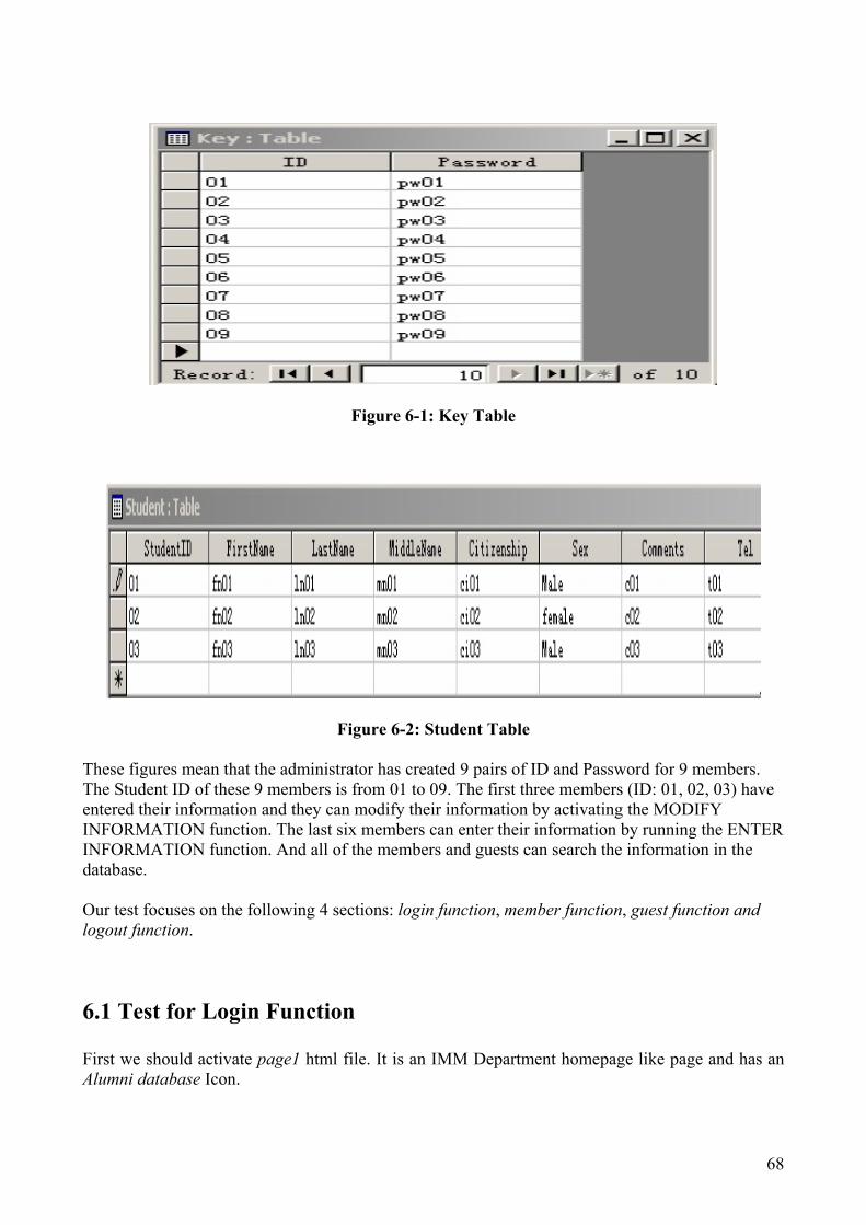
68
Figure 6-1: Key Table
Figure 6-2: Student Table These figures mean that the administrator has created 9 pairs of ID and Password for 9 members. The Student ID of these 9 members is from 01 to 09. The first three members (ID: 01, 02, 03) have entered their information and they can modify their information by activating the MODIFY INFORMATION function. The last six members can enter their information by running the ENTER INFORMATION function. And all of the members and guests can search the information in the database. Our test focuses on the following 4 sections: login function, member function, guest function and logout function.
6.1 Test for Login Function First we should activate page1 html file. It is an IMM Department homepage like page and has an Alumni database Icon.

69
Figure 6-3: Page 1
After pressing the Alumni database Icon, we can go to the page2 (Figure 6-4). It has a link to the login frame.
Figure 6-4: Page 2
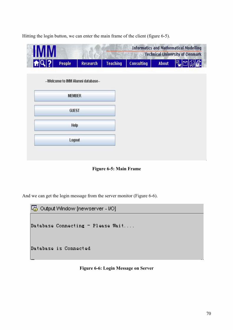
70
Hitting the login button, we can enter the main frame of the client (figure 6-5).
Figure 6-5: Main Frame
And we can get the login message from the server monitor (Figure 6-6).
Figure 6-6: Login Message on Server

71
6.2 Test for Member Function
6.2.1 Test for checking ID and Password
Before entering the Member frame, the user will be asked to fill in user’s ID and Password to check with the member status. (Figure 6-7)
Figure 6-7: Check ID and Password Frame
If the user inputs wrong ID or Password, a warning message (Figure 6-8) will appear and the page returns to the main frame.
Figure 6-8: Error ID or Password

72
6.2.2 Test for ENTER INFORMATION Function
If user’s ID and Password match the contents saved in Key table, user can go to the member frame (Figure 6-9).
Figure 6-9 Member Frame
User can hit ENTER INFORMATION button to enter ENTER INFORMATION frame. Here user can find a tabbed frame (figure 6-10) to add user’s information to the database.
Figure 6-10: Enter Information Frame

73
Hints:
• The blank boxes are essential information, and the others are optional information. • This function accepts all 23 strings as one complete legal input, so please fill in all blanks. • If this function detects that you have input some information in the database before, it will
refuse your request. That means only the last 6 members can add their information to database by using this function.
• So this function can only be used one time. If your information has been saved in the database, you could only use MODIFY INFORMATION function to change your information.
Suppose Member (05) try to enter his information to the database (Figure6-11). (Figure 6-12).
Figure 6-11: Member (05) Frame
Click tab”General”, and then go to page of general information to enter the information of general. The situations of clicking button “Education”, “Company”, and “Contact” are same as clicking tab”General”. It is shown as following figure (Figure 6-12).
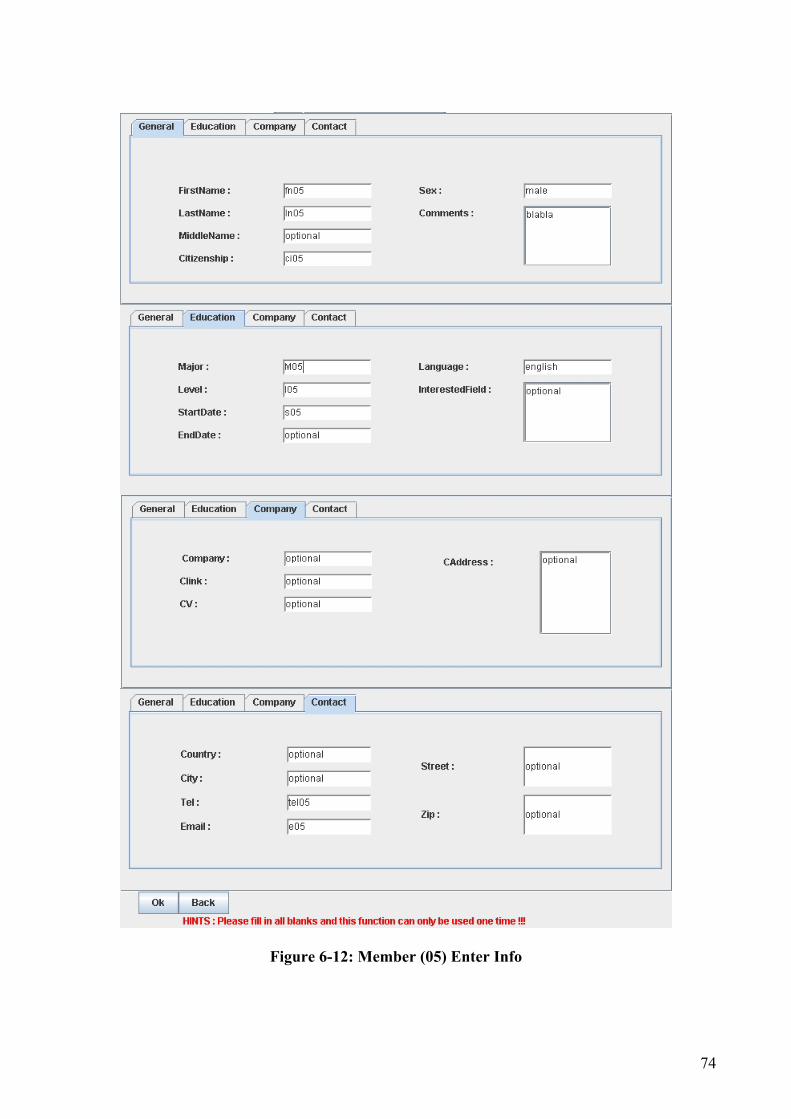
74
Figure 6-12: Member (05) Enter Info

75
When user entered all his/her information, we can see the new information has been stored in the database (Figure 6-13).
Figure 6-13: Member (05) Info Entered The administrator can also see the new member information on the server monitor (Figure 6-14).
Figure 6-14: Member (05) Info on Server
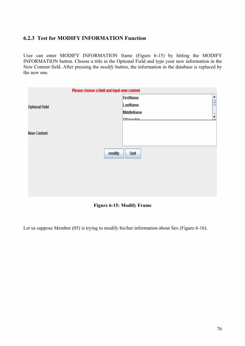
76
6.2.3 Test for MODIFY INFORMATION Function
User can enter MODIFY INFORMATION frame (Figure 6-15) by hitting the MODIFY INFORMATION button. Choose a title in the Optional Field and type your new information in the New Content field. After pressing the modify button, the information in the database is replaced by the new one.
Figure 6-15: Modify Frame Let us suppose Member (05) is trying to modify his/her information about Sex (Figure 6-16).

77
Figure 6-16: Member (05) Modify Info We can see the new information shown the member (05) is female ☺ (Figure 6-17).
Figure 6-17: Member (05) Modify Info The administrator can also get the changed information on the server monitor (Figure 6-18).
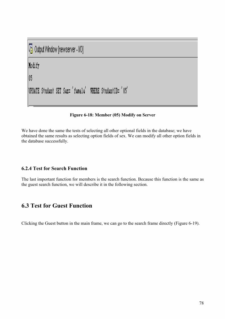
78
Figure 6-18: Member (05) Modify on Server
We have done the same the tests of selecting all other optional fields in the database; we have obtained the same results as selecting option fields of sex. We can modify all other option fields in the database successfully.
6.2.4 Test for Search Function
The last important function for members is the search function. Because this function is the same as the guest search function, we will describe it in the following section.
6.3 Test for Guest Function Clicking the Guest button in the main frame, we can go to the search frame directly (Figure 6-19).

79
Figure 6-19: Search Frame
Hints:
• Choose a entity in the keyword list. You must click the chosen keyword and the color of the box turn to purple.
• Type your search condition in the Condition field. • Press the search results button. • If you did wrong operation, you can get help information on the result window.
For instance, the following figure shows how to search the information of the members whose gender is female in the database (Figure 6-20).

80
Figure 6-20: Search Female in Database
We have done the tests of search functions for selecting keywords of First Name, Last Name, Major, Company, Language by using the same procedure as searching information according to the keyword of Sex. We have obtained the desired searching results successfully by the above mentioned keywords.

81
6.4 Test for Logout Function
The last button on the main frame is the logout button (Figure 6-21).
Figure 6-21: Logout Button We can logout the Alumni database safely by using this function. The following message (Figure 6-22)is shown on the Server monitor. It means one client has disconnected with the Server.
Figure 6-22: Logout Message on Server

82

83
Chapter 7
Conclusion We have described the requirements specification, technology background, designs and implementations of a generic database respectively in this project. Now we conclude on the achievements of this project and give some discussions for the future improvements in this chapter.
7.1 Achievements The objective if this project as mentioned earlier is to design and implementation of a generic database which contains the data on the education and work information of IMM former/current students. The database which we designed can contain a configurable internet-interface for accessing the database from the web. To conclude this report we want to emphasize and hope that this project is completed to all expectations. It has be a great value to us to see developments within the project, from the initial choice to design an alumni database to the final implementation in MS Access and JDBC. According to the test result of system, the project results a demonstrative version of IMM alumni database system working well on the web. We may conclude that our alumni database system fulfills its requirement specification. We also may conclude it achieves reusability and extensionality. We believe that this project provides us with the ability to understand and apply the fundamental methods of database design and implementation. We are satisfied with the work achieve on the project and value the experience and knowledge of database system and web application obtained.
7.2 Discussions and Future Improvements
7.2.1 Add More Functions In the Database
We may store more information and build more kinds of relationship in the database. In our opinion, the most important function of a database is powerful search function.
• We could set more keywords for searching the information such as the start date of study and the end date of study. It is helpful for students to search their classmates.

84
Another challenging keyword is the Interested Field. The company may use this condition to find out the students who interested in the company’s study fields. But how to grasp the concerned keywords from so much information of Interested Field is a problem.
• Add more search conditions is good way to reduce the domain of the searching
results. For example, we can try to search the information of a student, with three search condition, who is male, whose language is English and whose major is computer system engineering.
• Restricting the input information of the users can improve the efficiency of
searching. For example, in the Sex condition field, some users maybe input Male and some other users maybe like use keyword Man to express the same meaning. We can implement a drag list and on the list only has two choices Male and female to solve this problem in future.
We may consider using web-harvester as an extension of the system. The web-harvester is a net-search engine. It searches the web for data related to the one stored in the database. It generates a filtered and formatted list of data from which the administrator can choose items to be added to the database. We should study some particular knowledge about web-harvester to get the solution of it.
7.2.2 More Security Issues of the System
We may consider more security issues of the system including applet security, JDBC security, database security, and web security. Security of the system is a new and important challenge for the software developer. Considering more security issues can enhance the stability of the system. 1. The security problem of Access database. • Access database itself has some security tools to protect its’ data. Set Password is one common
way to keep the security of database. The main steps of setting the password are : * Open the database under the exclusive condition. * On the tools menu, point to Security, and then press Set Database Password * Type and confirm the Password The strongpoint of setting password is it could prevent the hackers from opening the database directly on server machine. But because this database permits the users login the system from internet, we have to type the password in the JDBC-ODBC bridge. So the hackers could get the password from the JDBC code easily if they intrude the server machine. If we do not have a good way to protect the code part of this system, the database password is useless. • Using user-level security, user and group permission and user and group accounts are some

85
other powerful tools to protect the database. But we did not find a way to implement JDBC together with these methods.
• MS Access has an object named page to view and work with data through Web page. It is a
special type of Web page. The administrator of the database can have the authority to operate the data from the Internet or an Intranet. But after discussing the risk of this attempt, we did not implement this function for the security problem.
2. The security problem of Applet.
As a whole, applets loaded over the net are prevented from reading and writing files on the client file system, and applets can only connect to the originating host. For the security problem, applets can't get the IP address of hosts on the network they are running on. And even if they knew ahead of time the IP address of a host on the network.
If you set the appletviewer in "unrestricted" mode, applets can connect to hosts on the internet. But it would bring great danger to your computer if foreign applets attack the system.
How to keep the security issue when running applets within a web browser? Traditionally we have been two approaches to do that.
One approach is to use a virtual machine that is capable of restricting the activities that the applet can perform on the client machine. The disadvantage is that is very difficult to get a truly safe virtual machine and sometime too many restrictions prevent an applet from doing any work
An alternative way is each applet comes complete with a digital signature that identifies the original publisher and virtually guarantees that the code cannot be modified in transit. The problem with this approach is that misplacing trust in a particular supplier can take terrible results.
With the development of Java language, the Applet becomes more and more flexible. Java2 security model allows applet access to specific resources on the user’s machine without the need for certificates.
3. The security problem of JDBC
The JDBC Driver must be registered on the JDBC DriverManager. The JDBC Driver can only get the access to its’ own data source. JDBC accepts java applications as trusted code, so the application can connect the
database.

86
An uncertificated java applet is seemed as untrusted code. And JDBC prevents applet from connecting the database.
If JDBC Driver certitudes the access to the data is secure and authentic, it can permit the applet to access the data source.
7.2.3 Some New Technologies
We may consider some other technologies to be applied in this project .Our database system in this project is not a big system, if we implement a large database system we’d better consider to use Oracle or SQL sever.
Although MS Access is inexpensive it works fine with a low/medium load, it does not scale well in busy servers and as more and more features are added the system performance is reduced. To avoid this we could migrate to MS SQL Server. SQL Server is the enterprise database system from Microsoft, it is far more robust and scalable and provides much better performance.
In web application, we would try to use XML, Java Servlet, and JSP technology to implement it.
Extensible Markup Language (XML) is an Industrial Standards Organization compliant subset of SGML (Standard Generalized Markup Language). XML is extensible because it is a meta-language that enables someone to write a Document Type Definition (DTD) such as HTML 4.0, and define the rules of the language so the document can be interpreted by the document receiver. The purpose of XML is to provide an easy-to-use subset of SGML that allows for custom tags to be processed. Custom tags will enable the definition, transmission, and interpretation of data structures between organizations.
Java Servlet is like CGI programs in that it runs on the server. However, it uses Java threads to avoid the memory disadvantages of CGI. We don't know enough about it to know about whether it suffers from the same security problems as CGI program. Using servlet, we can write a program that resides on the server which handles all our JDBC database calls.The web server calls this program when it receives a query. Like CGI, servlet generally returns a complete web page. As with CGI, to call a servlet from an applet; we'd open a socket to the web server, send our request, and receive the results in our applet. An important consideration for servlet is that our web server be capable of running it. Most web servers can be made to run servlet, if they don't already. JSP can be run on a variety of web servers. It is an extension of Java Servlet. This means (as we understand it) that JSP is creating by running a servlet which interprets the special HTML tags.

87
Bibliography [1] Thomas Connolly & Carolyn Begg Database Systems, Third Edition ADDISON WESLEY, 2002 [2] Philip M. Lewis, Arthur Bernstein & Michael Kifer Databases and Transaction Processing, An application-Oriented Approach ADDISON WESLEY, 2002 [3] Walter Savitch JAVA, An Introduction to Computer Science & Programming, International Edition Pearson Prentice Hall, 2004 [4] Paul Fischer Java, Graphical Users Interface Department of Informatics and Mathematical Modelling (IMM), Technical University of Denmark (DTU), 2003 [5] Jeffery D. Ullman & Jennifer Widom A First Course in Database System Pearson Prentice Hall, 1997 [6] Ian Summerville Software Engineering, Sixth Edition ADDISON WESLEY, 2001 [7] H. Garcia-molina, Jeffery D. Ullman & Jennifer Widom Database Systems, The Complete Book Pearson Prentice Hall, 2002 [8] Bob Villareal Access 2002 Programming by Example Queen, 2002 [9] Harvery Deitel, Paul Deitel Java How to Pragram, Fifth Edition Pearson Prentice Hall, 2003 [10] Khawar Zaman Ahmed & Cary E. Umrysh Developing Enterprise Java Application with J2EE and UML Addison Wesley, 2001
88
[11] Krik Knoernschid Java Design: Objects, UML, and Process Addison Wesley, 2001 [12] David C. Hay Requirements Analysis: From Business Views to Architecture Pearson Prince Hall, 2002 Web Recourses: [JDBC] The page of JDBC from Sun Java official web-site www.java.sun.com/products/JDBC [JSP] The page of JSP from Sun Java official web-site www.java.sun.com/products/JSP [Access] The page of Microsoft Office official web-site http://office.microsoft.com/home/ [APD] Making Access Project and Data Technologies Choices http://www.informit.com/articles/article.asp?p=27120 [Socket] An Introduction to Socket Programming http://www.uwo.ca/its/doc/courses/notes/socket/ [Database] Database Technologies http://www.develop.com/us/technology/

89
Appendix A : Project Schedule
(21.10.2003—20.04.2004)
Project Title: A Generic Database Student Name: Xiaoyu Sun (s011018)
Xiaofeng cao (s010415)
Supervisor: Paul Fischer
Duration Task name Content of actual work Start: 21.10.2003 End: 09.11.2003 3 weeks
Requirements Collecting
Two teachers/Paul Fischer or some other teacher Two graduates from DTU Five undergraduates in DTU Some related people from the different companies
Start: 10.11.2003 End: 31.11.2003 3 weeks
Techniques Review Database technology Java programming Internet applications
Start: 01.12.2003 End: 14.12.2003 2 weeks
Template Design and Modeling
Decide main functions of this project
Start: 12.15.2003 End: 29.02.2004 (Include Christmas and
Project Work Implementations
Requirements analysis Requirements specification System design Program

90
new year holiday)11weeks Start: 01.03.04 End: 14.03.04 2 weeks
Test and improvement Doing the test of system
Start: 15.03.04 End: 12.04.04 (Include Easter Holiday) 4 weeks
Forming the report Write and edit the final report
Start: 13.04.04 End: 20.04.04 1 week
Checking and rewriting Get the feedback from supervisor and do the modification of report

91
Appendix B: Requirements Collection
Name : Geng Yan Status : Current M.Sc Student at COM , DTU Contents :
• Personal information (Name, Grade, Received Degree, Email, Homepage, )
• Interested fields • Experience • Interested job
Name : Jianxin Liu Status : Current M.Sc Student at IMM , DTU Contents :
• Personal information (…, Courses) • Information about classmates • Chat room • Interested companies • Reunion info.
Name : Sun Xin Status : Former M.Sc Student at IMM , DTU Contents :
• News releases • Statistics of IMM
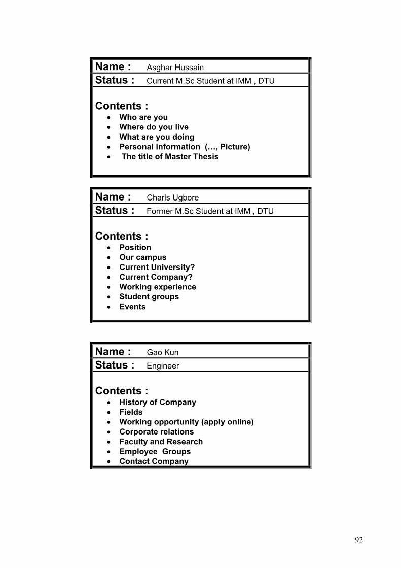
92
Name : Asghar Hussain Status : Current M.Sc Student at IMM , DTU Contents :
• Who are you • Where do you live • What are you doing • Personal information (…, Picture) • The title of Master Thesis
Name : Charls Ugbore Status : Former M.Sc Student at IMM , DTU Contents :
• Position • Our campus • Current University? • Current Company? • Working experience • Student groups • Events
Name : Gao Kun Status : Engineer Contents :
• History of Company • Fields • Working opportunity (apply online) • Corporate relations • Faculty and Research • Employee Groups • Contact Company

93
Name : Li ji Status : Former M.Sc Student at IMM , DTU Contents :
• Students information survey (everything) • Work offer • My class notes • Participate list (search) • Login/Logout
Name : Paul Fischer Status : Associate Professor at IMM,DTU Contents :
• Personal data (name, mail address, email, number of telephone)
• Education background (degree type, specialization, grade, projects)
• Work experience (field of work, related working companies, positions in the companies and contacting methods)
• Personal interests and their expectation
Name : Fleeming Stassen Status : Associate Professor at IMM,DTU Contents :
• Some students have several ID • Some students have different citizenships • Some students have middle name

94
Appendix c: List of Source Code This database system includes two parts : 1. Access Database
a. Two Tables : Key : To save the Student ID and Password Student : To save the information of members
b. One Form StudentForm : The form of the Table Student
2. Java Program
Applet Version:
a. Server Side : Newserver.java : The main function of Server Servant.java : To set the number of the ServerSorket HandlrequestL.java : To handle the requests gotten through the port. b. Client Side :
ClienFrame : It is a Java-Applet program and produces a class file named ClientFrame.class. It could be executed by a Web-page to transfer the request of Client to Server.
Conpanel.class, Companel.class, Edupanel.class and Gerneralpanel.class are used to build the tabbed panel for new members to enter their information into Database.
c. The Web-page part :
Page1.html : It is a IMM homepage like file. Page2.html : It has a link to Clientframe.class
Two DTU_file folders : They are used to save the pic and JScript files of the web- page.
• Application version
a. Server Side : Newserver.java : The main function of Server Servant.java : To set the number of the ServerSorket HandlrequestL.java : To handle the requests gotten through the port. b. Client Side :
Mainwindow : The main function of Client side. ClienFrame : It is a Java-Application program. It is used to handle the requirement
between server and client.

95
Conpanel.class, Companel.class, Edupanel.class and Gerneralpanel.class are used to build the tabbed panel for new members to enter their information into Database.