Ning Li, Xiaofeng Meng, Jing Nie ,andLiweiLin
8
IEEE SENSORS JOURNAL, VOL. 18, NO. 14, JULY 15, 2018 5715 A QCM Dew Point Sensor With Active Temperature Control Using Thermally Conductive Electrodes Ning Li, Xiaofeng Meng, Jing Nie , and Liwei Lin Abstract—A dew point (DP) sensor structure was proposed with active temperature control using the thermally conductive electrodes on the quartz crystal microbalance (QCM). Two copper wires were bonded on both sides of the QCM via the conductive adhesive as the main heat transfer components. The transmittal of the temperature and the fixation of sensitive cell were realized by the connection of electrode pins. Finite element analysis was carried out to theoretically validate the high- temperature transfer efficiency and good vibration characteristics of the structure with optimal dimensions. Gases with different DP were measured to evaluate the performance of the sensor. The accuracy of the DP sensor was found to be ±0.22 °C DP in the range of 5 °C DP ∼16 °C DP by referencing to a commercial MICHELL S4000 DP meter. Index Terms— Humidity, dew point sensor, quartz crystal microbalance, electrode, thermal transfer. I. I NTRODUCTION H UMIDITY measurement has attracted much attention for important applications in industry, agriculture and our daily life [1]–[4]. Among various schemes, the dew point (DP) temperature is internationally recognized as the most accurate method for humidity measurements [5]–[8]. It has been studied based on various techniques, including optical technologies [9], [10], impedance properties [11], integrated semiconductors [12], [13], quartz crystal microbal- ance (QCM) [14], [15] and many others [16], [17]. In the aforementioned schemes, QCM was regarded as a highly accurate method [18], [19] due to its measurement principle as expressed as in Eq. (1). f =− 2f 2 0 √ μ q ρ q m A (1) Where f 0 is the initial resonance frequency of the QCM without mass loading; m is the mass loading on the QCM Manuscript received April 25, 2018; accepted May 22, 2018. Date of pub- lication May 24, 2018; date of current version June 26, 2018. This work was supported in part by the National Natural Science Foundation of China under Grant 61473021 and Grant 61603349, in part by the Changjiang Scholars and Innovative Research Team in University under Grant IRT_16R02, and in part by the China Postdoctoral Science Foundation under Grant 2016M600893. The associate editor coordinating the review of this paper and approving it for publication was Dr. E. H. Yang. (Corresponding author: Jing Nie.) N. Li and X. Meng are with the Science and Technology on Inertial Laboratory, Beihang University, Beijing 100191, China (e-mail: [email protected]). J. Nie and L. Lin are with the Berkeley Sensor and Actuator Center, University of California at Berkeley, Berkeley, CA 94720 USA, and also with the Department of Mechanical Engineering University of California at Berkeley, Berkeley, CA 94720 USA (e-mail: [email protected]; [email protected]). Digital Object Identifier 10.1109/JSEN.2018.2840124 active area; A is the QCM active area; μ q is the shear modulus of the AT-cut quartz crystal (μ q = 2.947 × 10 11 g · cm −1 · S −2 ); ρ q is the density of quartz (ρ q = 2.643g · cm −3 ); and f is the frequency shift caused by the humidity mass loading on the QCM. In principle, results from a QCM sensor are related to the mass loading on the active area as well as the properties of the QCM. Due to its high sensitivity, QCM is often used in scientific research and laboratories as one of the methods to measure micro-mass with high accuracy. However, the use of a QCM dew point sensor in a dust particle concentration environment is subject to certain restrictions because the dust particles deposit on the surface of the electrode and bring about additional mass changes, thereby failing to accurately characterize the moisture condensation state with frequency changes. Until now, only few company has the commercial instruments for measuring dew point based on QCM. Handheld dew point meter S505 made by company of CS and QMA2030 made by the company of MICHELL are the most commonly used commercial QCM dew point sensor. The measurement accuracy of the commercial QCM dew point sensor is about 2 °C DP. Most of them provide qualitative reference for the production environment in the industrial field and the accuracy is difficult to meet high-precision measurement requirements. We designed the structure of the new dew point sensor and analyze the structural stability. The purpose is also to be able to give full play to the advantages of QCM so that it can further improve the measurement accuracy and stability of commercial sensors. In the structural design in [20], the QCM was fixed by a copper crystal housing on the QCM surface and the connector can affect the vibration characteristics of the QCM and the measurement accuracy. In [21], the QCM was placed directly on the surface of the Peltier cooler which could cause the formation of an air layer between the QCM and the Peltier cooler if the QCM was not properly placed. The air layer can affect the thermal transfer process and measurement accuracy. In our previous studies in [22], the QCM was fixed by the copper stents via two thermal gaskets on the non-electrode part of the QCM. This fixation has little effect on the vibration characteristics of the QCM and exhibits good measurement accuracy. However, for small size QCMs, it is difficult to fix the QCM with accurate precision. This paper proposed a new QCM dew point sensor structure using two copper wires electrodes bonded on both sides of the QCM by conductive adhesives. The temperature informa- tion can be obtained by the two copper wire electrodes as 1558-1748 © 2018 IEEE. Personal use is permitted, but republication/redistribution requires IEEE permission. See http://www.ieee.org/publications_standards/publications/rights/index.html for more information.
Transcript of Ning Li, Xiaofeng Meng, Jing Nie ,andLiweiLin
IEEE SENSORS JOURNAL, VOL. 18, NO. 14, JULY 15, 2018 5715
A QCM Dew Point Sensor With Active TemperatureControl Using Thermally Conductive Electrodes
Ning Li, Xiaofeng Meng, Jing Nie , and Liwei Lin
Abstract— A dew point (DP) sensor structure was proposedwith active temperature control using the thermally conductiveelectrodes on the quartz crystal microbalance (QCM). Twocopper wires were bonded on both sides of the QCM via theconductive adhesive as the main heat transfer components. Thetransmittal of the temperature and the fixation of sensitivecell were realized by the connection of electrode pins. Finiteelement analysis was carried out to theoretically validate the high-temperature transfer efficiency and good vibration characteristicsof the structure with optimal dimensions. Gases with differentDP were measured to evaluate the performance of the sensor.The accuracy of the DP sensor was found to be ±0.22 °C DP inthe range of 5 °C DP ∼16 °C DP by referencing to a commercialMICHELL S4000 DP meter.
Index Terms— Humidity, dew point sensor, quartz crystalmicrobalance, electrode, thermal transfer.
I. INTRODUCTION
HUMIDITY measurement has attracted much attentionfor important applications in industry, agriculture and
our daily life [1]–[4]. Among various schemes, the dewpoint (DP) temperature is internationally recognized as themost accurate method for humidity measurements [5]–[8].It has been studied based on various techniques, includingoptical technologies [9], [10], impedance properties [11],integrated semiconductors [12], [13], quartz crystal microbal-ance (QCM) [14], [15] and many others [16], [17]. In theaforementioned schemes, QCM was regarded as a highlyaccurate method [18], [19] due to its measurement principleas expressed as in Eq. (1).
� f = − 2f20√
μqρq
�m
A(1)
Where f0 is the initial resonance frequency of the QCMwithout mass loading; m is the mass loading on the QCM
Manuscript received April 25, 2018; accepted May 22, 2018. Date of pub-lication May 24, 2018; date of current version June 26, 2018. This work wassupported in part by the National Natural Science Foundation of China underGrant 61473021 and Grant 61603349, in part by the Changjiang Scholars andInnovative Research Team in University under Grant IRT_16R02, and in partby the China Postdoctoral Science Foundation under Grant 2016M600893.The associate editor coordinating the review of this paper and approving itfor publication was Dr. E. H. Yang. (Corresponding author: Jing Nie.)
N. Li and X. Meng are with the Science and Technology onInertial Laboratory, Beihang University, Beijing 100191, China (e-mail:[email protected]).
J. Nie and L. Lin are with the Berkeley Sensor and Actuator Center,University of California at Berkeley, Berkeley, CA 94720 USA, and alsowith the Department of Mechanical Engineering University of Californiaat Berkeley, Berkeley, CA 94720 USA (e-mail: [email protected];[email protected]).
Digital Object Identifier 10.1109/JSEN.2018.2840124
active area; A is the QCM active area; μq is the shear modulusof the AT-cut quartz crystal (μq = 2.947×10¹¹g ·cm−1 ·S−2);ρq is the density of quartz (ρq = 2.643g · cm−3); and � fis the frequency shift caused by the humidity mass loadingon the QCM. In principle, results from a QCM sensor arerelated to the mass loading on the active area as well asthe properties of the QCM. Due to its high sensitivity, QCMis often used in scientific research and laboratories as oneof the methods to measure micro-mass with high accuracy.However, the use of a QCM dew point sensor in a dust particleconcentration environment is subject to certain restrictionsbecause the dust particles deposit on the surface of theelectrode and bring about additional mass changes, therebyfailing to accurately characterize the moisture condensationstate with frequency changes. Until now, only few companyhas the commercial instruments for measuring dew point basedon QCM. Handheld dew point meter S505 made by companyof CS and QMA2030 made by the company of MICHELL arethe most commonly used commercial QCM dew point sensor.The measurement accuracy of the commercial QCM dew pointsensor is about 2 °C DP. Most of them provide qualitativereference for the production environment in the industrialfield and the accuracy is difficult to meet high-precisionmeasurement requirements. We designed the structure of thenew dew point sensor and analyze the structural stability. Thepurpose is also to be able to give full play to the advantages ofQCM so that it can further improve the measurement accuracyand stability of commercial sensors.
In the structural design in [20], the QCM was fixed by acopper crystal housing on the QCM surface and the connectorcan affect the vibration characteristics of the QCM and themeasurement accuracy. In [21], the QCM was placed directlyon the surface of the Peltier cooler which could cause theformation of an air layer between the QCM and the Peltiercooler if the QCM was not properly placed. The air layer canaffect the thermal transfer process and measurement accuracy.In our previous studies in [22], the QCM was fixed by thecopper stents via two thermal gaskets on the non-electrodepart of the QCM. This fixation has little effect on the vibrationcharacteristics of the QCM and exhibits good measurementaccuracy. However, for small size QCMs, it is difficult to fixthe QCM with accurate precision.
This paper proposed a new QCM dew point sensor structureusing two copper wires electrodes bonded on both sides ofthe QCM by conductive adhesives. The temperature informa-tion can be obtained by the two copper wire electrodes as
1558-1748 © 2018 IEEE. Personal use is permitted, but republication/redistribution requires IEEE permission.See http://www.ieee.org/publications_standards/publications/rights/index.html for more information.

5716 IEEE SENSORS JOURNAL, VOL. 18, NO. 14, JULY 15, 2018
Fig. 1. The dew point sensor structure. (a) The schematic diagram of the sensor structure. (b) The top view of the sensitive QCM cell; (c) The sectionalview of the sensitive QCM cell.
they have high thermal conductivity and they also serve asmechanical supports to secure the sensitive QCM cell. As such,the installation process would have little effect on the vibrationcharacteristics of the QCM. Finite Element analysis (FEA) wasconducted for the optimal dimensions of the copper wires onthe electrode pin on both sides of the QCM. Experiments werecarried out to evaluate the performances of the sensor structureand results proved good performances.
II. THE DESIGN OF THE SENSOR STRUCTURE
Fig. 1 shows the schematic diagram of the design. The lensabove the QCM was used to observe the change of phasestate on the surface of the QCM electrode. The hollow boltpressed on the lens was used for fixation. Two copper wireswere bonded on the electrode pin on both sides of the QCMby the conductive adhesive. Elastic gasket was used to protectthe copper wires and for the better heat transfer efficiency. Thecopper plates were placed on the surface of the copper pillarfor the transfer of heat and electricity. The PT100 embedded inthe copper pillar recorded the temperature and the central pillarmade of Polytetrafluoroethylene (PTFE) was used to isolatethe two copper pillars. The Peltier cooler under the copperpillars played the role of refrigeration source and the heat sinkwas attached to the surface of Peltier cooler in order to improvethe refrigeration efficiency. In the experiments, external gaseswith different concentrations of water molecules went throughthe surface of the QCM and the Peltier cooler cooled the QCMfor water condensations. Fig. 1 (b) & (c) show the sensitivecell of the structure from different views. The length (L)and width (W ) of electrode pin, and the thickness (δ) ofthe conductive adhesive had important effects on both heattransfer and vibration characteristics of the QCM and FEAwas performed to obtain the optimal parameters.
III. FEA OF THE SENSOR STRUCTURE
FEA was performed by using ANSYS 17.0 [23] to analyzethe effect of conductive adhesive on both the temperaturetransmission and vibration performance of the QCM cells. Thefrequency of the AT cut QCM used in the experiment was4 MHz and the QCM dimensions were: crystal thickness (tq)
Fig. 2. The FEA model for the thermal analysis. The grey-color part wasthe quartz, while the blue- and the purple-color parts were silver. The density,thermal conductivity and specific heat capacity of the quartz were 2650 kg/m3,6.8 W/(m ·K) and 800 J/(kg ·K); while those for the silver were 10490 kg/m3,429 W/(m · K) and 234 J/(kg · K). The initial temperature was set as 22 °C,and the refrigeration temperature was set as 2 °C. The convective heat transfercoefficient was set as 10 W/(m2 · °C).
of 0.416 mm; diameter (dq) of 8.6 mm; and silver electrodediameter (de) of 5.2 mm.
A. Thermal Transfer Analysis of the Structure
In order to evaluate the thermal transfer process of thestructure, a steady state thermal analysis based on ANSYS17.0 was conducted. Since the thermal conductivity of thesilver is far greater than that of the quartz, the heat wasassumed to transport in the silver electrode layer quicklybefore the transport process to the quartz layer. Hexahedralgrids with the quantity of 36192 were used in the FEA analysisas shown in Fig. 2. The blue part was the region of theconductive adhesive bonded and it was also the region forrefrigeration. The conductive adhesive was directly applied onthe electrode pin on both sides of the QCM, such that δ hadlittle effect on the thermal transfer process. The values of Land W were taken into consideration in the thermal analysisand W was chosen as a fixed parameter of 1.6 mm from acommercial product and the effect of L was analyzed from0.1 mm to 1.7 mm.
LI et al.: QCM DP SENSOR WITH ACTIVE TEMPERATURE CONTROL 5717
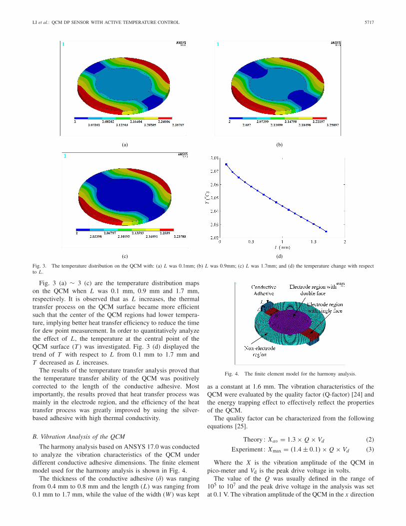
Fig. 3. The temperature distribution on the QCM with: (a) L was 0.1mm; (b) L was 0.9mm; (c) L was 1.7mm; and (d) the temperature change with respectto L .
Fig. 3 (a) ∼ 3 (c) are the temperature distribution mapson the QCM when L was 0.1 mm, 0.9 mm and 1.7 mm,respectively. It is observed that as L increases, the thermaltransfer process on the QCM surface became more efficientsuch that the center of the QCM regions had lower tempera-ture, implying better heat transfer efficiency to reduce the timefor dew point measurement. In order to quantitatively analyzethe effect of L, the temperature at the central point of theQCM surface (T ) was investigated. Fig. 3 (d) displayed thetrend of T with respect to L from 0.1 mm to 1.7 mm andT decreased as L increases.
The results of the temperature transfer analysis proved thatthe temperature transfer ability of the QCM was positivelycorrected to the length of the conductive adhesive. Mostimportantly, the results proved that heat transfer process wasmainly in the electrode region, and the efficiency of the heattransfer process was greatly improved by using the silver-based adhesive with high thermal conductivity.
B. Vibration Analysis of the QCM
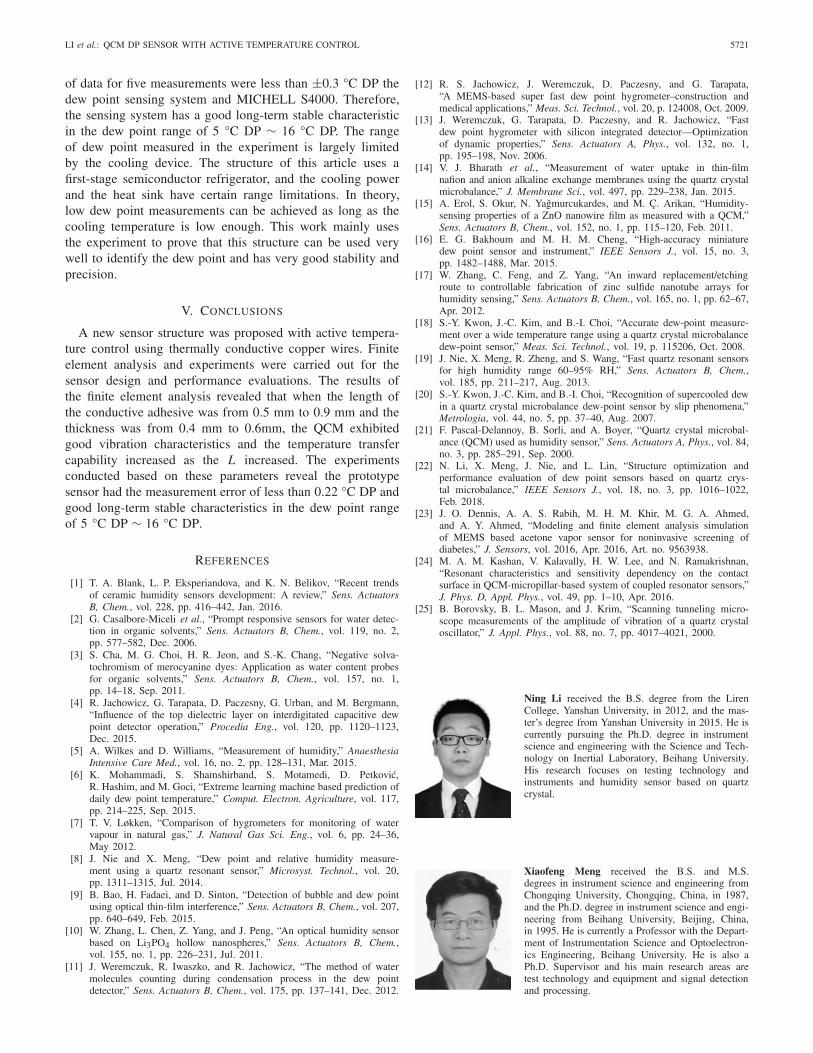
The harmony analysis based on ANSYS 17.0 was conductedto analyze the vibration characteristics of the QCM underdifferent conductive adhesive dimensions. The finite elementmodel used for the harmony analysis is shown in Fig. 4.
The thickness of the conductive adhesive (δ) was rangingfrom 0.4 mm to 0.8 mm and the length (L) was ranging from0.1 mm to 1.7 mm, while the value of the width (W ) was kept
Fig. 4. The finite element model for the harmony analysis.
as a constant at 1.6 mm. The vibration characteristics of theQCM were evaluated by the quality factor (Q-factor) [24] andthe energy trapping effect to effectively reflect the propertiesof the QCM.
The quality factor can be characterized from the followingequations [25].
Theory : Xav = 1.3 × Q × Vd (2)
Experiment : Xmax = (1.4 ± 0.1) × Q × Vd (3)
Where the X is the vibration amplitude of the QCM inpico-meter and Vd is the peak drive voltage in volts.
The value of the Q was usually defined in the range of105 to 107 and the peak drive voltage in the analysis was setat 0.1 V. The vibration amplitude of the QCM in the x direction

5718 IEEE SENSORS JOURNAL, VOL. 18, NO. 14, JULY 15, 2018
Fig. 5. The Q factor simulation results of the QCM with L from 0.1 mm to 1.7 mm and δ from 0.4 mm to 0.8 mm. (a) The results of the extreme analysis.(b) The results of the overall distribution analysis.
Fig. 6. The energy distribution analysis results of the QCM when with L from 0.1 mm to 1.7 mm and δ from 0.4 mm to 0.8 mm. (a) Results of the extremeanalysis. (b) Results of the overall distribution analysis.
was much larger than those in the y and z direction such thatthe vibration amplitude in the x direction (ux ) was used for X .
The energy trapping effect of the QCM was evaluatedby calculating the energy distribution (E) of the QCM. Theenergy distribution was the ratio of the energy in the electroderegion and the energy on the total QCM surface. The energywas expressed by the vibration displacement of the QCM andthe calculation of the energy distribution was described inEq. (4).
E =∫ x= 1
2 de
x=− 12 de
|rx |/∫ x= 1
2 dq
x=− 12 dq
|rx | (4)
Where the rx is the QCM vibration displacement in the xdirection; de is the diameter of the QCM electrode; and dq isthe diameter of the QCM. In this work, when the E value waslarger than 80%, the QCM is defined to exhibit good vibrationcharacteristics.
Fig. 5 & 6 show the simulation results of the Q factorand energy distribution analysis of the QCM under differentconductive adhesive dimensions, when L was from 0.1 mmto 1.7 mm and δ from 0.4 mm to 0.8 mm in Fig. 5 andthe extreme point (Fig. 5 (a)) and the overall distributions(Fig. 5 (b)) were analyzed separately. The results showed thatthe Q factor reach the maximum value at the point when L
was 0.9 mm and δ was 0.7 mm and most of the vibrationamplitude values were at the range of 0 nm ∼ 2 nm. In orderto get better approximations in the overall distribution analysis,the ux values larger than 10 nm were set to 2 nm. Fig. 5 (b)shows the results of the overall distribution analysis. The valueof ux = 1.3 nm in Fig. 5 (b) was set as the boundary of QCMwith good vibration characteristics. The results indicated thatmost (59/85) of the ux values were larger than 1.3 nm asgood vibration characteristics in the whole range. Especiallywhen the L values were from 0.5 mm to 0.9 mm and the δvalues were from 0.4 mm to 0.6 mm, the ux values exhibiteda relative stable region and were larger than 1.3 nm.
The analysis of the energy distribution of the QCM wasconducted as the energy trapping analysis. The results wereshowed in Fig. 6. Fig. 6 (a) shows the results of extremeanalysis and when L was 1.7 mm and δ was 0.7 mm, the valuereached maximum. Fig. 6 (b) shows the results of the overalldistribution analysis. The value of E = 80% was set as theboundary of QCM with good vibration characteristics. Theresults indicated that most of the values were larger than 80%.By setting the values lower than 70% as a value of 70%,Fig. 6 (b) shows that QCM could get better vibration propertieswith L from 0.5 mm to 0.9 mm and δ from 0.4 mm to 0.6mm.
From the FEA, it is observed that the optimal L and δ valuesfor the Q factor and energy distribution analysis results of

LI et al.: QCM DP SENSOR WITH ACTIVE TEMPERATURE CONTROL 5719
Fig. 7. The dew point measurement system.
the QCM are not the same. However, regions having highervalues are those when L was from 0.5 mm to 0.9 mm and δwas from 0.4 mm to 0.6 mm. In the subsequent experiments,the parameters of the conductive adhesive were selected in thisregion to get better QCM vibration characteristics.
IV. EXPERIMENTS AND RESULTS
A. Experiment Setup
Experiments were carried out to evaluate the performance ofthe designed sensor. In the experiments, the initial temperaturewas 20 °C; the atmospheric pressure was 101 KPa; and thevalue of the gas flow rate was 0.35 L/min. The measurementsystem of the experiment is shown in Fig. 7 and the purity ofthe N2 is 99.999%.
The experiment system was consisted of three parts: the dewpoint generation system, the dew point measurement systemand the designed sensor. The dew point generation systemwas used to generate gases with different moisture levels bycontrolling the quantity of water vapor using flow controllers.
The dew point measurement system was consisted of aPC, the Agilent 4294A, the temperature control module,and the temperature collection module. A PC was used tocontrol the whole measurement system through a LabVIEWprogram. The Agilent 4294A was used to drive the QCMand transmit the frequency of the QCM to the PC. Thetemperature control module controlled the temperature of theQCM through keeping the input current of the Peltier coolerat a constant value of 2 A. The temperature collection modulecollected the temperature of the QCM through the PT100.In the experiments, the gas went through the commercial dewpoint system, MICHELL S4000, and the designed sensor inthe parallel mode.
B. Studies of Temperature Effect on Dew Point Measurements
The influence of temperature on the dew point measure-ments mainly has two parts: the effect of temperature on thefrequency, and the difference in measurement due to the sensorstructure. During the measuring process when using the dewpoint sensor with active temperature control, the temperature
Fig. 8. The temperature effect on the QCM frequency.
of the QCM surface changed all the time and it affected thestability of the QCM frequency characterizations. Therefore,the investigation of the temperature effect on the stability ofthe QCM frequency is necessary. Experiments were conductedto examine the temperature effect on the QCM frequency withthe temperature reducing from 20.34 °Cto 1.84 °C and thefrequency variation was recorded in Fig. 8.
The frequency change of the QCM was mainly caused bythe temperature difference in different regions on the QCMsurface. Fig. 8 shows that the maximum frequency shift causedby the temperature effect is only 13.123 Hz, which is verysmall compared to the resonant frequency of the QCM (theresonant of the QCM used in the experiment was 4 MHz)and it is much lower than the frequency shift caused by vaporcondensations.
In the designed sensor structure, the PT100 was embeddedin the copper pillar. The temperature differences between thePT100 and the temperature on the QCM surface may alsohave effects on the measurement results. Experiments wereconducted by using two PT100 devices: one was bonded onthe QCM surface, and the other was embedded in the copperpillar. As temperature decreased from 19.86 °C to 2.46 °C,the QCM temperature decreased from 20.2 °C to 4.86 °C asshown in Fig. 9.

5720 IEEE SENSORS JOURNAL, VOL. 18, NO. 14, JULY 15, 2018
Fig. 9. The temperature variations of the QCM (TQCM) and the copper wire(TPT100) from 20 °C to 4 °C.
Fig. 10. The measurement results for the dew point.
The relationship between the TPT100 and the TQCM couldbe described by a cubic-curve equation as showed in Eq. (5).The R-square of the fitting curve was 0.9999 for better fittingeffect.
TQCM = −0.001833T3PT100 + 0.03529T 2
PT100
+ 0.922TPT100 + 2.409 (5)
Where TQCM is the temperature of the QCM surface andTPT100 is the temperature that acquired from the copper wire.The relationship was used to obtain the true temperature of theQCM according to the temperature measured by the PT100 onthe copper wire.
C. Performance Evaluation of the Sensor
To evaluate the performance of the sensor, the initial tem-perature was set at 19.88 °C and the input current of thePeltier was 2 A. The measurement results in Fig. 10 show thatwhen the temperature (measured by PT100) was far from thedew point temperature, the frequency of the QCM was relativestable as water was not condensed on the QCM surface andthe frequency fluctuations in this period was mainly causedby the instability of the QCM and the effect of the gas flow.When the temperature reached the dew point temperature,there would be an obvious frequency shift which was causedby the water condensation on the QCM surface. It is foundthat the significant shift of the frequency occurred twice during
Fig. 11. The results of the dew point measurement in the range of 5 °C DPto 16 °C DP.
Fig. 12. Stability of the sensor for 8 hours.
the cooling process. The first time was relative small as thedew point was reached but the amount of water condensed onthe QCM surface was not large. The second significant shiftof the frequency occurred as the main moisture condensationson the quartz surface. In this work, the first frequency shiftof the QCM was used as the dew point. By identifying thetemperature when the frequency shift appeared, we can get atemperature of 6.63 °C. With the help of Eq. (5), we can getthe accurate dew point temperature as 9.54 °C. By comparingwith the dew point measured by MICHELL S4000 at 9.41 °C,the difference was 0.13 °C.
The performance of the designed dew point sensor wasevaluated through examining its measurement stability and itsrepeatability in the range of 5 °C DP to 16 °C DP. To evaluatethe stability of the sensor, gases with standard dew pointof 5.31 °C DP, 7.38 °C DP, 9.41 °C DP, 11.65 °C DP,13.63 °C DP, and 15.58 °C DP were measured. The mea-surement results were showed in Fig.11 and errors were0.03 °C DP, −0.02 °C DP, 0.13 °C DP, 0.14 °C DP, 0.22 °C DPand 0.21 °C DP, respectively.
To test the long-term stability of the sensor, we selected sixgroups for measurements for five times as shown in Fig. 12.The measurements were repeated at environment temperatureof 20 °C for every 2 hours for 8 hours. Slight variations inthe measured values were observed over time and the six sets
LI et al.: QCM DP SENSOR WITH ACTIVE TEMPERATURE CONTROL 5721
of data for five measurements were less than ±0.3 °C DP thedew point sensing system and MICHELL S4000. Therefore,the sensing system has a good long-term stable characteristicin the dew point range of 5 °C DP ∼ 16 °C DP. The rangeof dew point measured in the experiment is largely limitedby the cooling device. The structure of this article uses afirst-stage semiconductor refrigerator, and the cooling powerand the heat sink have certain range limitations. In theory,low dew point measurements can be achieved as long as thecooling temperature is low enough. This work mainly usesthe experiment to prove that this structure can be used verywell to identify the dew point and has very good stability andprecision.
V. CONCLUSIONS
A new sensor structure was proposed with active tempera-ture control using thermally conductive copper wires. Finiteelement analysis and experiments were carried out for thesensor design and performance evaluations. The results ofthe finite element analysis revealed that when the length ofthe conductive adhesive was from 0.5 mm to 0.9 mm and thethickness was from 0.4 mm to 0.6mm, the QCM exhibitedgood vibration characteristics and the temperature transfercapability increased as the L increased. The experimentsconducted based on these parameters reveal the prototypesensor had the measurement error of less than 0.22 °C DP andgood long-term stable characteristics in the dew point rangeof 5 °C DP ∼ 16 °C DP.
REFERENCES
[1] T. A. Blank, L. P. Eksperiandova, and K. N. Belikov, “Recent trendsof ceramic humidity sensors development: A review,” Sens. ActuatorsB, Chem., vol. 228, pp. 416–442, Jan. 2016.
[2] G. Casalbore-Miceli et al., “Prompt responsive sensors for water detec-tion in organic solvents,” Sens. Actuators B, Chem., vol. 119, no. 2,pp. 577–582, Dec. 2006.
[3] S. Cha, M. G. Choi, H. R. Jeon, and S.-K. Chang, “Negative solva-tochromism of merocyanine dyes: Application as water content probesfor organic solvents,” Sens. Actuators B, Chem., vol. 157, no. 1,pp. 14–18, Sep. 2011.
[4] R. Jachowicz, G. Tarapata, D. Paczesny, G. Urban, and M. Bergmann,“Influence of the top dielectric layer on interdigitated capacitive dewpoint detector operation,” Procedia Eng., vol. 120, pp. 1120–1123,Dec. 2015.
[5] A. Wilkes and D. Williams, “Measurement of humidity,” AnaesthesiaIntensive Care Med., vol. 16, no. 2, pp. 128–131, Mar. 2015.
[6] K. Mohammadi, S. Shamshirband, S. Motamedi, D. Petkovic,R. Hashim, and M. Goci, “Extreme learning machine based prediction ofdaily dew point temperature,” Comput. Electron. Agriculture, vol. 117,pp. 214–225, Sep. 2015.
[7] T. V. Løkken, “Comparison of hygrometers for monitoring of watervapour in natural gas,” J. Natural Gas Sci. Eng., vol. 6, pp. 24–36,May 2012.
[8] J. Nie and X. Meng, “Dew point and relative humidity measure-ment using a quartz resonant sensor,” Microsyst. Technol., vol. 20,pp. 1311–1315, Jul. 2014.
[9] B. Bao, H. Fadaei, and D. Sinton, “Detection of bubble and dew pointusing optical thin-film interference,” Sens. Actuators B, Chem., vol. 207,pp. 640–649, Feb. 2015.
[10] W. Zhang, L. Chen, Z. Yang, and J. Peng, “An optical humidity sensorbased on Li3PO4 hollow nanospheres,” Sens. Actuators B, Chem.,vol. 155, no. 1, pp. 226–231, Jul. 2011.
[11] J. Weremczuk, R. Iwaszko, and R. Jachowicz, “The method of watermolecules counting during condensation process in the dew pointdetector,” Sens. Actuators B, Chem., vol. 175, pp. 137–141, Dec. 2012.
[12] R. S. Jachowicz, J. Weremczuk, D. Paczesny, and G. Tarapata,“A MEMS-based super fast dew point hygrometer–construction andmedical applications,” Meas. Sci. Technol., vol. 20, p. 124008, Oct. 2009.
[13] J. Weremczuk, G. Tarapata, D. Paczesny, and R. Jachowicz, “Fastdew point hygrometer with silicon integrated detector—Optimizationof dynamic properties,” Sens. Actuators A, Phys., vol. 132, no. 1,pp. 195–198, Nov. 2006.
[14] V. J. Bharath et al., “Measurement of water uptake in thin-filmnafion and anion alkaline exchange membranes using the quartz crystalmicrobalance,” J. Membrane Sci., vol. 497, pp. 229–238, Jan. 2015.
[15] A. Erol, S. Okur, N. Yagmurcukardes, and M. Ç. Arikan, “Humidity-sensing properties of a ZnO nanowire film as measured with a QCM,”Sens. Actuators B, Chem., vol. 152, no. 1, pp. 115–120, Feb. 2011.
[16] E. G. Bakhoum and M. H. M. Cheng, “High-accuracy miniaturedew point sensor and instrument,” IEEE Sensors J., vol. 15, no. 3,pp. 1482–1488, Mar. 2015.
[17] W. Zhang, C. Feng, and Z. Yang, “An inward replacement/etchingroute to controllable fabrication of zinc sulfide nanotube arrays forhumidity sensing,” Sens. Actuators B, Chem., vol. 165, no. 1, pp. 62–67,Apr. 2012.
[18] S.-Y. Kwon, J.-C. Kim, and B.-I. Choi, “Accurate dew-point measure-ment over a wide temperature range using a quartz crystal microbalancedew-point sensor,” Meas. Sci. Technol., vol. 19, p. 115206, Oct. 2008.
[19] J. Nie, X. Meng, R. Zheng, and S. Wang, “Fast quartz resonant sensorsfor high humidity range 60–95% RH,” Sens. Actuators B, Chem.,vol. 185, pp. 211–217, Aug. 2013.
[20] S.-Y. Kwon, J.-C. Kim, and B.-I. Choi, “Recognition of supercooled dewin a quartz crystal microbalance dew-point sensor by slip phenomena,”Metrologia, vol. 44, no. 5, pp. 37–40, Aug. 2007.
[21] F. Pascal-Delannoy, B. Sorli, and A. Boyer, “Quartz crystal microbal-ance (QCM) used as humidity sensor,” Sens. Actuators A, Phys., vol. 84,no. 3, pp. 285–291, Sep. 2000.
[22] N. Li, X. Meng, J. Nie, and L. Lin, “Structure optimization andperformance evaluation of dew point sensors based on quartz crys-tal microbalance,” IEEE Sensors J., vol. 18, no. 3, pp. 1016–1022,Feb. 2018.
[23] J. O. Dennis, A. A. S. Rabih, M. H. M. Khir, M. G. A. Ahmed,and A. Y. Ahmed, “Modeling and finite element analysis simulationof MEMS based acetone vapor sensor for noninvasive screening ofdiabetes,” J. Sensors, vol. 2016, Apr. 2016, Art. no. 9563938.
[24] M. A. M. Kashan, V. Kalavally, H. W. Lee, and N. Ramakrishnan,“Resonant characteristics and sensitivity dependency on the contactsurface in QCM-micropillar-based system of coupled resonator sensors,”J. Phys. D, Appl. Phys., vol. 49, pp. 1–10, Apr. 2016.
[25] B. Borovsky, B. L. Mason, and J. Krim, “Scanning tunneling micro-scope measurements of the amplitude of vibration of a quartz crystaloscillator,” J. Appl. Phys., vol. 88, no. 7, pp. 4017–4021, 2000.
Ning Li received the B.S. degree from the LirenCollege, Yanshan University, in 2012, and the mas-ter’s degree from Yanshan University in 2015. He iscurrently pursuing the Ph.D. degree in instrumentscience and engineering with the Science and Tech-nology on Inertial Laboratory, Beihang University.His research focuses on testing technology andinstruments and humidity sensor based on quartzcrystal.
Xiaofeng Meng received the B.S. and M.S.degrees in instrument science and engineering fromChongqing University, Chongqing, China, in 1987,and the Ph.D. degree in instrument science and engi-neering from Beihang University, Beijing, China,in 1995. He is currently a Professor with the Depart-ment of Instrumentation Science and Optoelectron-ics Engineering, Beihang University. He is also aPh.D. Supervisor and his main research areas aretest technology and equipment and signal detectionand processing.
5722 IEEE SENSORS JOURNAL, VOL. 18, NO. 14, JULY 15, 2018
Jing Nie received the B.S. degree from the Informa-tion Engineering Department, Aerospace Engineer-ing University, Beijing, China, in 2006, the M.S.degree from the Materials Science and Engineer-ing Department, Lanzhou University of Technology,Lanzhou, China, in 2009, and the Ph.D. degree fromthe Measurement Control and Information Tech-nology Department, Beihang University, Beijing,in 2014. He held a post-doctoral position at theDepartment of Instrumentation Science and Opto-electronics Engineering, Beihang University, from
2015 to 2016. He holds a post-doctoral position with the Departmentof Mechanical Engineering and the Berkeley Sensor and Actuator Center(BSAC), University of California at Berkeley. His research interests includedew point and humidity sensor, instrumentation and test technology, and signaldetection and processing.
Liwei Lin received the B.S. degree from the PowerMechanical Engineering Department, National TsingHua University, Hsinchu, Taiwan, in 1986, andthe M.S. and Ph.D. degrees from the MechanicalEngineering Department, University of Californiaat Berkeley (UC Berkeley), Berkeley, CA, USA,in 1991 and 1993, respectively. He is currently theJames Marshall Wells Professor with the Departmentof Mechanical Engineering and the Co-Director withthe Berkeley Sensor and Actuator Center, UC Berke-ley. He has published more than 200 journal papers.
His research interests include microelectromechanical systems (MEMS),nanoelectromechanical systems, nanotechnology, the design and manufactur-ing of micro sensors and micro actuators, the development of micromachiningprocesses by silicon surface/bulk micromachining, micro molding process,and mechanical issues in MEMS, such as heat transfer, solid/fluid mechanics,and dynamics. He is a Fellow of ASME. Dr. Lin is an Editor of theNorth and South America for the journal Sensors and Actuators A: Physical.