WTC for Tel Aviv-4 - NIST
12
FORENSIC STUDY OF THE STEEL IN THE WORLD TRADE CENTER Thomas A. Siewert 1 , J. David McColskey 1 , Chris McCowan 1 , Frank W. Gayle 2 , William E. Luecke 2, Stephen W. Banovic 2 , Tim Foecke 2 , and Richard F. Fields 2 1 National Institute of Standards and Technology, Materials Reliability Division, Boulder, CO 80305, 2 Metallurgy Division, Gaithersburg, MD 20878, [email protected] ABSTRACT In September of 2002, the National Institute of Standards and Technology began a two-year investigation into the World Trade Center (WTC) disaster of September 11, 2001. Now almost complete, the investigation addresses many aspects of the catastrophe, from occupant egress to structural stability, with the goal of gaining valuable information for interested parties, such as emergency responders and the structural code bodies. The complete plan and some initial reports from the NIST investigation are available at <http://wtc.nist.gov>. A major part of the investigation is the metallurgical analysis of structural steel from the World Trade Center. The analysis includes characterization of the mechanical properties, failure modes, and temperature excursions seen by the steel. This report on the metallurgical investigation describes the structure of the towers, and properties of the steel recovered from the site at a range of temperatures and deformation rates. INTRODUCTION Constructed in the late 1960’s and early 1970’s, the 110 story WTC towers employed a novel tube construction, designed to increase the interior space. The core was a conventionally framed structure, albeit with massive columns, that primarily carried gravity loads (the majority of the floor system, as well as the elevators and HVAC system). The perimeter of the building resisted the majority of the wind loads as well as carried the remainder of the gravity loads. It was assembled from closely spaced 14 in x 14 in box columns that gave the building its characteristic exterior. Figure 1 shows a prefabricated perimeter column panel being hoisted into place. Once in place, the new columns were bolted to the existing columns (below), and the deep spandrels horizontal plates) were bolted together side-to-side using splice plates. Inside the building, each individual floor enclosed an acre of wall-free, open space. Lightweight floor trusses, also visible in Figure 1, spanned the open space between the core and perimeter columns in a two-dimensional lattice, and supported a 4 in thick lightweight concrete floor. At both the core and perimeter, truss seats transferred the floor truss loads to the walls. Because of the enormous size of the construction job, many different companies provided structural components for the buildings. Four different fabricators produced components in the fire and impact zones relevant to the NIST investigation. Pacific Car and Foundry of Seattle fabricated the perimeter panel sections on the west coast and shipped them to a staging area in New Jersey before assembly in Manhattan. These three-column assemblies were produced primarily using steel from Yawata Iron and Steel (now Nippon Steel), but domestic steel (less than 10 % of the components) was also used for some of the plates on the inner side of the column. The structural engineering plans called for fourteen different yield strengths of steel in the perimeter columns, of which twelve were actually used.
Transcript of WTC for Tel Aviv-4 - NIST

FORENSIC STUDY OF THE STEEL IN THE WORLD TRADE CENTER
Thomas A. Siewert1, J. David McColskey
1, Chris McCowan
1, Frank W. Gayle
2, William E.
Luecke2,
Stephen W. Banovic2, Tim Foecke
2, and Richard F. Fields
2
1National Institute of Standards and Technology, Materials Reliability Division, Boulder, CO
80305, 2Metallurgy Division, Gaithersburg, MD 20878, [email protected]
ABSTRACT
In September of 2002, the National Institute of Standards and Technology began a
two-year investigation into the World Trade Center (WTC) disaster of September 11, 2001.
Now almost complete, the investigation addresses many aspects of the catastrophe, from
occupant egress to structural stability, with the goal of gaining valuable information for
interested parties, such as emergency responders and the structural code bodies. The complete
plan and some initial reports from the NIST investigation are available at
<http://wtc.nist.gov>.
A major part of the investigation is the metallurgical analysis of structural steel from
the World Trade Center. The analysis includes characterization of the mechanical properties,
failure modes, and temperature excursions seen by the steel. This report on the metallurgical
investigation describes the structure of the towers, and properties of the steel recovered from
the site at a range of temperatures and deformation rates.
INTRODUCTION
Constructed in the late 1960’s and early 1970’s, the 110 story WTC towers employed
a novel tube construction, designed to increase the interior space. The core was a
conventionally framed structure, albeit with massive columns, that primarily carried gravity
loads (the majority of the floor system, as well as the elevators and HVAC system). The
perimeter of the building resisted the majority of the wind loads as well as carried the
remainder of the gravity loads. It was assembled from closely spaced 14 in x 14 in box
columns that gave the building its characteristic exterior. Figure 1 shows a prefabricated
perimeter column panel being hoisted into place. Once in place, the new columns were bolted
to the existing columns (below), and the deep spandrels horizontal plates) were bolted
together side-to-side using splice plates. Inside the building, each individual floor enclosed an
acre of wall-free, open space. Lightweight floor trusses, also visible in Figure 1, spanned the
open space between the core and perimeter columns in a two-dimensional lattice, and
supported a 4 in thick lightweight concrete floor. At both the core and perimeter, truss seats
transferred the floor truss loads to the walls.
Because of the enormous size of the construction job, many different companies
provided structural components for the buildings. Four different fabricators produced
components in the fire and impact zones relevant to the NIST investigation. Pacific Car and
Foundry of Seattle fabricated the perimeter panel sections on the west coast and shipped them
to a staging area in New Jersey before assembly in Manhattan. These three-column
assemblies were produced primarily using steel from Yawata Iron and Steel (now Nippon
Steel), but domestic steel (less than 10 % of the components) was also used for some of the
plates on the inner side of the column. The structural engineering plans called for fourteen
different yield strengths of steel in the perimeter columns, of which twelve were actually
used.

The core of the buildings employed two different types of columns. Stanray Pacific of
Los Angeles fabricated the massive welded box columns from plates up to 7 in thick. The
steel for these columns came almost exclusively from Japanese and British mills. These
massive box columns were more common in the lower stories of both towers, with a transition
to rolled wide-flange columns in the upper stories. Because the airplane impact in WTC 2
was in the transition area, about half of the core columns in floors of interest were the welded
box variety. In WTC 1, with a higher impact location, the core columns were primarily rolled
wide-flange shapes. Montague-Betts of Roanoke, Virginia, fabricated these rolled shapes for
the beams and columns in the core. The columns, many of which were the largest standard
size available, also came primarily from Yawata Iron and Steel. Most of the core columns
were specified to the requirements of ASTM Standard A36, which describes a common
construction steel with a yield strength of 36 ksi.
Laclede Steel of St. Louis fabricated the thousands of floor trusses from steel made in
electric arc furnaces at their mill. The individual elements of the floor trusses were specified
as a mixture of A36 and the higher strength (Fy = 50 ksi) A242 steel. Although the design
called for a mixture of the two steels, NIST has found that most elements met the
requirements of the higher strength steel (A242).
RECOVERY AND CATALOGING OF THE STEEL
Beginning in October 2001, the Building Performance Assessment Team (BPAT, led
by the Federal Emergency Management Agency and American Society of Civil Engineers)
and members of the Structural Engineers Association of New York (SEAoNY), began work
to identify and collect WTC structural steel. They collected these pieces from the various
recovery yards where debris, including the steel, had been taken during the cleanup effort.
NIST joined the recovery effort and provided an area for safe storage of the steel for later
forensic investigation.
A major task for the NIST investigation was cataloging the recovered structural steel
elements (perimeter panels, core columns, floor trusses, bolts, etc.) for further evaluation
and/or testing relative to the fire and structural response of the buildings. NIST has cataloged
these 236 elements, mostly from WTC 1 and WTC 2, which represent between 0.25 % to 0.5
% of the 200,000 tons of steel used in the construction of the two towers.
Critical to this task was the determination of the original, as-built location of the
recovered elements within the buildings. The buildings were complex, with the 14 specified
grades of steel having strengths ranging from 36 ksi to 100 ksi. To keep track of the material
during construction, each piece was given a serial number indicating the location in the
building. The numbers were embossed by stampings and/or painted stencils (Figure 2). In
many cases the serial numbers, or at least a partial identifier, survived the collapse and
subsequent recovery events. After correlating the identifiers with the structural plans for the
buildings, 41 distinct perimeter panel sections were unambiguously identified from the two
towers, and the location of 12 core columns was established. The following pieces of special
interest were found:
WTC1 - 4 perimeter panels directly hit by the aircraft (Figure 3),
- 22 perimeter panels from critical floors (91-101),
- 2 core columns from the fire-affected floors,
WTC 2
- 4 perimeter panels from near the impact floors,
- 2 core columns from the impact floors with possible impact damage.

Additionally, floor truss material and pieces of channel that connected the floor trusses
to the core columns were recovered; however, the original location of these structural
elements within the buildings could not be identified.
Based on the markings, all identified perimeter and core columns were found to
correlate one-to-one with the minimum yield strength specified by the design drawings, with
the exception that 100 ksi steel was substituted for all specified 85 ksi and 90 ksi plates. The
recovered structural elements provided representative samples of the 12 grades of perimeter
panel material actually used, two grades of core column material (representing 99 %, by total
number, of the columns), and both grades of the floor truss material.
FAILURE ANALYSIS
Documentation of damage features and failure modes of the structural steel
components plays an important role in (1) ascertaining the structural response of the
buildings, and the materials used in their construction, upon the impact of the aircraft, (2)
estimating the extent of internal damage, (3) yielding insights into the structural integrity of
the towers leading up to collapse, and (4) aiding in the determination of possible
mechanism(s) responsible for the collapse of each tower.
This aspect of the investigation was separated into two sections: 1) pre-collapse
analysis concentrating on impact damage sustained by the exterior panel sections, based upon
photographic and video images, and 2) damage characteristics of the recovered structural steel
elements. Of particular importance were the components located near the airplane impact
region on the north face of WTC 1 and the south face of WTC 2, and in those areas where fire
was known to be present.
Extensive image processing was used on photographs received from news
organizations and the public to determine pre-collapse damage to the perimeter panels.
Figure 4 shows the impact image used to extract perimeter column failure mode information
from WTC 1. The four panels highlighted by colored boxes correspond to those in Figure 3.
These panels were damaged by the aircraft impact. Superimposed onto this figure is the
outline of the aircraft (Figure 4b). Careful examination of such images has allowed the
characterization of the types of columns failures as indicated.
Comparisons were made between such observed pre-collapse damage and the present
condition of the four recovered panels that were hit. This analysis indicated that two of the
impact-damaged panels are in a condition similar to that before the collapse. Some of the
extraneous damage can be attributed to the events during and after collapse, but the general
shape and appearance of the recovered pieces correspond well with the damage photographs.
An example is shown in Figure 5 showing panel M-2 (WTC 1, column line 130, floors 96 to
99; green panel in Figures 3 and 4). Damage to the lower columns was clearly associated
with impact, which caused columns 129 and 130 to bend inward at the 97th floor level, very
similar to what was revealed by the photographic observations. With this type of knowledge,
the response of the materials used in the buildings’ construction can be ascertained with
respect to the impact of the aircraft, and the ability of the aircraft impact models to reproduce
the event can be validated.
MECHANICAL PROPERTIES
Recovered steel was tested to determine whether it met the required minimum
properties, and to provide data for models of the aircraft impact and the resulting fires.

Mechanical property tests indicate that all the steels likely met all required minimum test
requirements. A plot of measured versus specified yield strength is given in Figure 6.
In addition to room temperature properties, data were generated on the effects of high
temperature on the mechanical properties of the steels and on the effects of high strain rates
on the mechanical properties of the steels. Figure 7 demonstrates the effects of temperature on
yield and tensile strengths of some of the WTC steels. As expected, the strengths decrease
with increasing temperature.
The mechanical properties of steel are sensitive to strain rate, and can exhibit
significantly enhanced strength at high strain rates, with important effects on building
response to impact. A higher strength of a column should lead to increased energy absorption
and reduction in momentum of the aircraft after impact, thereby reducing further damage
done to the interior of the building. Measured strain rate effects are given in Figure 8 for a 65
ksi perimeter column and a 36 ksi core column steel. As expected, the yield and ultimate
strengths increase with increasing strain rate.
Baseline, high temperature, and high strain rate properties have been supplied to the
modeling efforts of the NIST investigation, where they are being used in detailed models of
the towers and their collapse scenarios.
FOR MORE INFORMATION
Interim reports from the NIST investigation are available at <http://wtc.nist.gov>. A
draft final report will be released for public comment in December 2004 at the same site.
ACKNOWLDEDGEMENTS
The authors acknowledge John L. Gross and Stephen A. Cauffman (of NIST) who
arranged delivery of the recovered steel to NIST; William M. Pitts for obtaining permission to
use the photograph of Figure 4; and Michael A. Riley for drafting Figure 3.
DISCLAIMER
Certain commercial entities are identified in this document in order to trace the history
of the procedures and practices used. Such identification is not intended to imply
recommendation, endorsement, or implication that the entities, products, or materials are
necessarily the best available for the purpose, nor does such identification imply a finding of
fault or negligence by the National Institute of Standards and Technology.
The policy of NIST is to use the International System of Units (metric units) in all
publications. In this document, however, units are presented in metric units or the inch-pound
system, whichever is prevalent in the relevant technical discipline.
Publication of NIST; not subject to copyright in the U.S.

Figure 1. A three-column perimeter panel being lifted into place (left). Arrangement of
perimeter panels and floor trusses connecting the perimeter columns and the tower core
structure. (source unknown)
Splice plates
Floor truss
seats
Floor truss

Figure 2. Characteristic stenciling found on the lower portions of the perimeter column
panels. Markings indicate this piece was in WTC 1 (“A”), column number 130, spanning
floors 93-96 (colored orange in Figures 3 and 4): this is the panel hit by the nose of the first
aircraft. (NIST)

Figure 3: North face of WTC 1. Impact damage to the perimeter columns with location of
structural elements recovered for the NIST investigation shown in color. Note that fires were
observed on floors 92 to 99 and 104. (FEMA BPAT 2002 as modified by NIST 2004)
91
92
93
94
95
96
97
100
98
99
101
102
103
C-40
M-30
M-20
N-9
N-99
N-8
C-22
N-101
N-13
S-9
N-7
M-2
M-26
M-27
C-80, Core column 603A: 92-95
HH, Core column 605A: 98-101

Figure 4: Enhanced photographs used to determine pre-collapse damage to the perimeter
panels of WTC 1. a) Colored boxes indicate location of recovered panels that were damaged
as a result of aircraft impact, b) Outline of airplane overlaid on impact damage with
indications of location and type of localized damage. Red boxes - cut metal components, blue
- broken vertical column connection bolts, green - failure of longitudinal welds in the box
columns, and yellow – indeterminate damage.
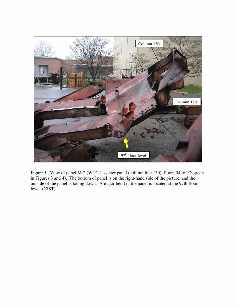
Figure 5: View of panel M-2 (WTC 1, center panel (column line 130), floors 94 to 97; green
in Figures 3 and 4). The bottom of panel is on the right-hand side of the picture, and the
outside of the panel is facing down. A major bend in the panel is located at the 97th floor
level. (NIST)
97th floor level
Column 129
Column 130

20 40 60 80 100 120
20
40
60
80
100
120
200 400 600 800
200
400
600
800
Specified Yield Strength, MPa
Measure
d Y
ield
Str
ength
, M
Pa
ksi
ksi
Figure 6. Specified yield strength versus averaged measured yield strength on WTC steels
tested at room temperature. The few anomalously low data can be attributed to damage
incurred in the collapse that removed the yield point behavior, or to the natural and accepted
strength variability of structural steel.

Figure 7. Normalized yield strength and ultimate tensile strength measured as function of
temperature. Model curve is based on historical data for WTC era steels.

Figure 8. Ultimate and yield strengths measured as a function of strain rate for two
column steels. It is estimated that strain rates during the airplane impact ranged as high as
500 s-1
to 1000 s-1
.