NIST NCSTAR 1-1J: Design, Installation, and Operation of Fuel Systems for Emergency Power in WTC 7
84
NIST NCSTAR 1-1J Federal Building and Fire Safety Investigation of the World Trade Center Disaster Documentation of the Fuel System for Emergency Power in World Trade Center 7 Raymond A. Grill Duane A. Johnson
-
Upload
jay-marton -
Category
Documents
-
view
225 -
download
0
description
The collapse of World Trade Center (WTC) 1, 2, and 7 resulted from structural damage from direct and indirect effects of aircraft impact and the ensuing fires. Thus, for collapse analyses of these buildings, knowledge of the physical state of the structural and fire safety systems prior to the aircraft impact is essential. To obtain information for the collapse analysis of the buildings, National Institute of Standards and Technology reviewed design and construction documents, correspondence, and memoranda related to the building projects; interviewed individuals involved in the design, construction, and maintenance of the buildings; obtained information from regulatory and emergency services agencies of New York City; and reviewed books and published journal and magazine articles related to the WTC building projects.
Transcript of NIST NCSTAR 1-1J: Design, Installation, and Operation of Fuel Systems for Emergency Power in WTC 7

NIST NCSTAR 1-1J
Federal Building and Fire Safety Investigation of the World Trade Center Disaster
Documentation of the Fuel System for Emergency Power in World Trade Center 7
Raymond A. Grill Duane A. Johnson

NIST NCSTAR 1-1J
Federal Building and Fire Safety Investigation of the World Trade Center Disaster
Documentation of the Fuel System for Emergency Power in World Trade Center 7 Raymond A. Grill Duane A. Johnson Rolf Jensen & Associates, Inc. September 2005
U.S. Department of Commerce Carlos M. Gutierrez, Secretary Technology Administration Michelle O’Neill, Acting Under Secretary for Technology National Institute of Standards and Technology William Jeffrey, Director
Disclaimer No. 1
Certain commercial entities, equipment, products, or materials are identified in this document in order to describe a procedure or concept adequately or to trace the history of the procedures and practices used. Such identification is not intended to imply recommendation, endorsement, or implication that the entities, products, materials, or equipment are necessarily the best available for the purpose. Nor does such identification imply a finding of fault or negligence by the National Institute of Standards and Technology.
Disclaimer No. 2
The policy of NIST is to use the International System of Units (metric units) in all publications. In this document, however, units are presented in metric units or the inch-pound system, whichever is prevalent in the discipline.
Disclaimer No. 3
Pursuant to section 7 of the National Construction Safety Team Act, the NIST Director has determined that certain evidence received by NIST in the course of this Investigation is “voluntarily provided safety-related information” that is “not directly related to the building failure being investigated” and that “disclosure of that information would inhibit the voluntary provision of that type of information” (15 USC 7306c).
In addition, a substantial portion of the evidence collected by NIST in the course of the Investigation has been provided to NIST under nondisclosure agreements.
Disclaimer No. 4
NIST takes no position as to whether the design or construction of a WTC building was compliant with any code since, due to the destruction of the WTC buildings, NIST could not verify the actual (or as-built) construction, the properties and condition of the materials used, or changes to the original construction made over the life of the buildings. In addition, NIST could not verify the interpretations of codes used by applicable authorities in determining compliance when implementing building codes. Where an Investigation report states whether a system was designed or installed as required by a code provision, NIST has documentary or anecdotal evidence indicating whether the requirement was met, or NIST has independently conducted tests or analyses indicating whether the requirement was met.
Use in Legal Proceedings
No part of any report resulting from a NIST investigation into a structural failure or from an investigation under the National Construction Safety Team Act may be used in any suit or action for damages arising out of any matter mentioned in such report (15 USC 281a; as amended by P.L. 107-231).
National Institute of Standards and Technology National Construction Safety Team Act Report 1-1J Natl. Inst. Stand. Technol. Natl. Constr. Sfty. Tm. Act Rpt. 1-1J, 84 pages (September 2005) CODEN: NSPUE2
U.S. GOVERNMENT PRINTING OFFICE WASHINGTON: 2005 _________________________________________ For sale by the Superintendent of Documents, U.S. Government Printing Office Internet: bookstore.gpo.gov — Phone: (202) 512-1800 — Fax: (202) 512-2250 Mail: Stop SSOP, Washington, DC 20402-0001

ABSTRACT
This report was prepared to support the analysis of building and fire codes and standards of the National Institute of Standards and Technology World Trade Center (WTC) Investigation. As part of the investigation of WTC 7, the fuel oil distribution system is being analyzed as a possible cause of fire initiation. The purpose of this report is to document the fuel oil distribution systems (including all fuel oil tanks, pumps, generators, routing of the piping, and system functions) and the associated fire protection features of the fuel oil system that existed in WTC 7 at the time of the collapse.
Keywords: Compartmentation, day tanks, diesel fuel, emergency generators, emergency power, fire protection, fire safety, fire sprinklers, fuel oil distribution system, fuel oil pumps, inspections, storage tanks, World Trade Center.
NIST NCSTAR 1-1J, WTC Investigation iii

Abstract
iv NIST NCSTAR 1-1J, WTC Investigation
This page intentionally left blank.

TABLE OF CONTENTS
Abstract ........................................................................................................................................................ iii List of Figures .............................................................................................................................................. ix List of Tables ............................................................................................................................................... xi List of Acronyms and Abbreviations .........................................................................................................xiii Metric Conversion Table ............................................................................................................................ xv Glossary ..................................................................................................................................................... xix Preface ....................................................................................................................................................... xxi Executive Summary ................................................................................................................................. xxxi
Chapter 1 Introduction ................................................................................................................................. 1
Chapter 2 Fuel Oil Provisions of the BCNYC ............................................................................................. 3
2.1 General Requirements...................................................................................................................... 3 2.2 Fuel Oil Storage Equipment............................................................................................................. 3 2.3 Location of Tanks ............................................................................................................................ 4 2.4 Piping .............................................................................................................................................. 6 2.5 Controls............................................................................................................................................ 9
Chapter 3 Base Building Design (1987)....................................................................................................11
3.1 Basic Layout .................................................................................................................................. 11 3.2 Component Details......................................................................................................................... 11 3.3 Fire Protection................................................................................................................................ 12 3.4 References...................................................................................................................................... 13
Chapter 4 Ambassador Construction Modification (1994) ..................................................................... 17
4.1 Basic Layout .................................................................................................................................. 17 4.2 Component Details......................................................................................................................... 17 4.3 Fire Protection................................................................................................................................ 18 4.4 References...................................................................................................................................... 18
NIST NCSTAR 1-1J, WTC Investigation v

Table of Contents
Chapter 5 American Express Modification (1994) ................................................................................... 21
5.1 Basic Layout .................................................................................................................................. 21 5.2 Component Details......................................................................................................................... 21 5.3 Fire Protection................................................................................................................................ 22 5.4 References...................................................................................................................................... 22
Chapter 6 Mayor’s Office of Emergency Management Modification (1999) .......................................... 25
6.1 Basic Layout .................................................................................................................................. 25 6.2 Component Details......................................................................................................................... 26 6.3 Fire Protection................................................................................................................................ 27 6.4 References...................................................................................................................................... 27
Chapter 7 Salomon Brothers Addition (1990).......................................................................................... 31
7.1 Basic Layout .................................................................................................................................. 31 7.2 Component Details......................................................................................................................... 31 7.3 Fire Protection................................................................................................................................ 32 7.4 References...................................................................................................................................... 32
Chapter 8 Final Configuration ................................................................................................................... 35
Chapter 9 System Performance ................................................................................................................ 41
9.1 Base Building Fuel Oil Distribution System.................................................................................. 41 9.1.1 Liquid Level Switches/Detectors and Collecting Pans/Rupture Basins ............................. 41 9.1.2 Fusible Link Gate Valve..................................................................................................... 42 9.1.3 Anti-siphon Valve and Check Valve.................................................................................. 42 9.1.4 Foot Valve .......................................................................................................................... 43 9.1.5 Pressure Relief Valve ......................................................................................................... 43 9.1.6 Solenoid Valve ................................................................................................................... 43 9.1.7 Tank Selector Valve ........................................................................................................... 43
9.2 Salomon Brothers Fuel Oil Distribution System ........................................................................... 46 9.3 System Capacities .......................................................................................................................... 48
vi NIST NCSTAR 1-1J, WTC Investigation

Draft for Public Comment
Chapter 10 Maintenance History................................................................................................................. 49
NIST NCSTAR 1-1J, WTC Investigation vii
Table of Contents
viii NIST NCSTAR 1-1J, WTC Investigation
This page intentionally left blank.

LIST OF FIGURES
Figure P–1. The eight projects in the federal building and fire safety investigation of the WTC disaster. ...............................................................................................................................xxiii
Figure 3–1. Base Building 1st floor fuel oil distribution plan. .................................................................. 14 Figure 3–2. Base Building 5th floor fuel oil distribution plan. .................................................................. 14 Figure 3–3. Base Building section plan of fuel oil distribution components. ............................................ 15
Figure 4–1. First floor fuel oil distribution plan after the Ambassador Construction modification. ......... 19 Figure 4–2. Ninth floor fuel oil distribution plan after the Ambassador Construction modification......... 19 Figure 4–3. Section plan of fuel oil distribution components after the Ambassador Construction
modification. .......................................................................................................................... 20
Figure 5–1. First floor fuel oil distribution plan after the American Express modification....................... 23 Figure 5–2. Seventh floor fuel oil distribution plan after the American Express modification. ................ 23 Figure 5–3. Eighth floor fuel oil distribution plan after the American Express modification. .................. 23 Figure 5–4. Section plan of fuel oil distribution components after the American Express
modification. .......................................................................................................................... 24
Figure 6–1. First floor fuel oil distribution plan after the OEM modification. .......................................... 28 Figure 6–2. Seventh floor fuel oil distribution plan after the OEM modification. .................................... 28 Figure 6–3. Section plan of fuel oil distribution components after the OEM modification....................... 29
Figure 7–1. First floor fuel oil distribution plan after the Salomon Brothers addition. ............................. 33 Figure 7–2. Fifth floor fuel oil distribution plan after the Salomon Brothers addition.............................. 33 Figure 7–3. Section plan of fuel oil distribution components after the Salomon Brothers addition.......... 34
Figure 8–1. Section plan showing the final locations of the fuel oil distribution components. ................. 36 Figure 8–2. Final location of 1st floor fuel oil distribution components. .................................................. 37 Figure 8–3. Final location of 5th floor fuel oil distribution components. .................................................. 37 Figure 8–4. Final location of 7th floor fuel oil distribution components. .................................................. 38 Figure 8–5. Final location of 8th floor fuel oil distribution components. .................................................. 38 Figure 8–6. Final location of 9th floor fuel oil distribution components. .................................................. 39
NIST NCSTAR 1-1J, WTC Investigation ix

List of Figures
x NIST NCSTAR 1-1J, WTC Investigation
Figure 9–1. Typical layout of critical devices in Base Building sub-systems. .......................................... 44 Figure 9–2. Layout of critical devices in Salomon Brothers system. ........................................................ 47

LIST OF TABLES
Table P–1. Federal building and fire safety investigation of the WTC disaster. .....................................xxii Table P–2. Public meetings and briefings of the WTC Investigation...................................................... xxv
Table 9–1. Critical fuel oil devices installed in Base Building sub-systems. ............................................ 45 Table 9–2. Capacity of fuel oil components throughout WTC 7. .............................................................. 48
Table 10–1. Maintenance schedule of fuel oil pumps and generators. ...................................................... 49
NIST NCSTAR 1-1J, WTC Investigation xi

List of Tables
xii NIST NCSTAR 1-1J, WTC Investigation
This page intentionally left blank.

LIST OF ACRONYMS AND ABBREVIATIONS
Acronyms
BCNYC Building Code of the City of New York (Local Law 76)
BSA New York City Board of Standards and Appeals
FOR fuel oil return
FOS fuel oil supply
MER Mechanical Equipment Room
NIST National Institute of Standards and Technology
OEM Mayor’s Office of Emergency Management
PANYNJ Port Authority of New York and New Jersey
RS Reference Standard to the Building Code of the City of New York
WTC World Trade Center
WTC 1 World Trade Center 1 (North Tower)
WTC 2 World Trade Center 2 (South Tower)
WTC 7 World Trade Center 7
Abbreviations
°F degrees Fahrenheit
ft foot
ft2 square foot
gal gallon
gph gallons per hour
gpm gallons per minute
h hour
hp horsepower
Hz hertz
in. inch
kVa kilovoltampere
kW kilowatt
psi pounds per square inch
NIST NCSTAR 1-1J, WTC Investigation xiii

List of Acronyms and Abbreviations
xiv NIST NCSTAR 1-1J, WTC Investigation
rpm revolutions per minute
V volt

METRIC CONVERSION TABLE
To convert from to Multiply by
AREA AND SECOND MOMENT OF AREA square foot (ft2) square meter (m2) 9.290 304 E-02
square inch (in.2) square meter (m2) 6.4516 E-04
square inch (in.2) square centimeter (cm2) 6.4516 E+00
square yard (yd2) square meter (m2) 8.361 274 E-01
ENERGY (includes WORK)
kilowatt hour (kW ⋅ h) joule (J) 3.6 E+06
quad (1015 BtuIT) joule (J) 1.055 056 E+18
therm (U.S.) joule (J) 1.054 804 E+08
ton of TNT (energy equivalent) joule (J) 4.184 E+09
watt hour (W ⋅ h) joule (J) 3.6 E+03
watt second (W ⋅ s) joule (J) 1.0 E+00
FORCE dyne (dyn) newton (N) 1.0 E-05
kilogram-force (kgf) newton (N) 9.806 65 E+00
kilopond (kilogram-force) (kp) newton (N) 9.806 65 E+00
kip (1 kip=1,000 lbf) newton (N) 4.448 222 E+03
kip (1 kip=1,000 lbf) kilonewton (kN) 4.448 222 E+00
pound-force (lbf) newton (N) 4.448 222 E+00
FORCE DIVIDED BY LENGTH pound-force per foot (lbf/ft) newton per meter (N/m) 1.459 390 E+01
pound-force per inch (lbf/in.) newton per meter (N/m) 1.751 268 E+02
HEAT FLOW RATE calorieth per minute (calth/min) watt (W) 6.973 333 E-02
calorieth per second (calth/s) watt (W) 4.184 E+00
kilocalorieth per minute (kcalth/min) watt (W) 6.973 333 E+01
kilocalorieth per second (kcalth/s) watt (W) 4.184 E+03
NIST NCSTAR 1-1J, WTC Investigation xv

Metric Conversion Table
To convert from to Multiply by
LENGTH foot (ft) meter (m) 3.048 E-01
inch (in) meter (m) 2.54 E-02
inch (in.) centimeter (cm) 2.54 E+00
micron (m) meter (m) 1.0 E-06
yard (yd) meter (m) 9.144 E-01
MASS and MOMENT OF INERTIA kilogram-force second squared
per meter (kgf ⋅ s2/m) kilogram (kg) 9.806 65 E+00
pound foot squared (lb ⋅ ft2) kilogram meter squared (kg ⋅ m2) 4.214 011 E-02
pound inch squared (lb ⋅ in.2) kilogram meter squared (kg ⋅ m2) 2.926 397 E-04
ton, metric (t) kilogram (kg) 1.0 E+03
ton, short (2,000 lb) kilogram (kg) 9.071 847 E+02
MASS DIVIDED BY AREA pound per square foot (lb/ft2) kilogram per square meter (kg/m2) 4.882 428 E+00
pound per square inch (not pound force) (lb/in.2) kilogram per square meter (kg/m2) 7.030 696 E+02
MASS DIVIDED BY LENGTH pound per foot (lb/ft) kilogram per meter (kg/m) 1.488 164 E+00
pound per inch (lb/in.) kilogram per meter (kg/m) 1.785 797 E+01
pound per yard (lb/yd) kilogram per meter (kg/m) 4.960 546 E-01
PRESSURE or STRESS (FORCE DIVIDED BY AREA) kilogram-force per square centimeter (kgf/cm2) pascal (Pa) 9.806 65 E+04
kilogram-force per square meter (kgf/m2) pascal (Pa) 9.806 65 E+00
kilogram-force per square millimeter (kgf/mm2) pascal (Pa) 9.806 65 E+06
kip per square inch (ksi) (kip/in.2) pascal (Pa) 6.894 757 E+06
kip per square inch (ksi) (kip/in.2) kilopascal (kPa) 6.894 757 E+03
pound-force per square foot (lbf/ft2) pascal (Pa) 4.788 026 E+01
pound-force per square inch (psi) (lbf/in.2) pascal (Pa) 6.894 757 E+03
pound-force per square inch (psi) (lbf/in.2) kilopascal (kPa) 6.894 757 E+00
psi (pound-force per square inch) (lbf/in.2) pascal (Pa) 6.894 757 E+03
psi (pound-force per square inch) (lbf/in.2) kilopascal (kPa) 6.894 757 E+00
xvi NIST NCSTAR 1-1J, WTC Investigation

Metric Conversion Table
To convert from to Multiply by
TEMPERATURE
degree Celsius (°C) kelvin (K) T/K = t/°C + 273.15
degree centigrade degree Celsius (°C) t/°C ≈ t /deg. cent.
degree Fahrenheit (°F) degree Celsius (°C) t/°C = (t/°F - 32)/1.8
degree Fahrenheit (°F) kelvin (K) T/K = (t/°F + 459.67)/1.8
kelvin (K) degree Celsius (°C) t/°C = T/K 2 273.15
TEMPERATURE INTERVAL
degree Celsius (°C) kelvin (K) 1.0 E+00
degree centigrade degree Celsius (°C) 1.0 E+00
degree Fahrenheit (°F) degree Celsius (°C) 5.555 556 E-01
degree Fahrenheit (°F) kelvin (K) 5.555 556 E-01
degree Rankine (°R) kelvin (K) 5.555 556 E-01
VELOCITY (includes SPEED) foot per second (ft/s) meter per second (m/s) 3.048 E-01
inch per second (in./s) meter per second (m/s) 2.54 E-02
kilometer per hour (km/h) meter per second (m/s) 2.777 778 E-01
mile per hour (mi/h) kilometer per hour (km/h) 1.609 344 E+00
mile per minute (mi/min) meter per second (m/s) 2.682 24 E+01
VOLUME (includes CAPACITY) cubic foot (ft3) cubic meter (m3) 2.831 685 E-02
cubic inch (in.3 ) cubic meter (m3) 1.638 706 E-05
cubic yard (yd3) cubic meter (m3) 7.645 549 E-01
gallon (U.S.) (gal) cubic meter (m3) 3.785 412 E-03
gallon (U.S.) (gal) liter (L) 3.785 412 E+00
liter (L) cubic meter (m3) 1.0 E-03
ounce (U.S. fluid) (fl oz) cubic meter (m3) 2.957 353 E-05
ounce (U.S. fluid) (fl oz) milliliter (mL) 2.957 353 E+01
NIST NCSTAR 1-1J, WTC Investigation xvii

Metric Conversion Table
xviii NIST NCSTAR 1-1J, WTC Investigation
This page intentionally left blank

GLOSSARY
active fire protection – A means to help prevent the loss of life and property from fire by extinguishing, suppressing, or controlling a fire through functional systems. Sprinkler systems, fire alarm systems, and smoke control systems are examples of active fire protection.
combustible – A material that is not determined to be noncombustible.
dry pipe sprinkler system – A fire sprinkler system in which the piping up to the sprinkler heads is initially filled with air. Once a sprinkler head operates, water is released into the piping and continues to flow out the activated sprinkler(s) until the system is shut off.
fire alarm system – A system, automatic or manual, arranged to give a signal indicating a fire emergency and initiate the appropriate response.
fire resistance rating – The time in hours that materials or their assemblies will withstand fire exposure as determined by a fire test.
fireproofing – Materials or assemblies used to provide a fire resistance rating to a building component.
firestop – A solid or compact, tight closure to retard the spread of flames or hot gases within concealed spaces.
noncombustible – A material that, in the form in which it is used in construction, will not ignite and burn when subjected to fire. However, any material which liberates flammable gas when heated to any temperature up to 1,380 °F for 5 min shall not be considered noncombustible.
passive fire protection – Fire protection features that are incorporated into the building construction or building materials that do not rely on active fire protection methods to limit fire ignition, fire growth, or material failure. Fire separations and divisions, sprayed fire-resistive material, and enclosing structural members with noncombustible materials are examples of passive fire protection.
wet pipe sprinkler system – A fire sprinkler system in which the piping is filled with pressurized water at all times. Water is immediately discharged when a sprinkler head operates and continues to flow out the activated sprinkler(s) until the system is shut off.
NIST NCSTAR 1-1J, WTC Investigation xix

Glossary
xx NIST NCSTAR 1-1J, WTC Investigation
This page intentionally left blank.

PREFACE
Genesis of This Investigation
Immediately following the terrorist attack on the World Trade Center (WTC) on September 11, 2001, the Federal Emergency Management Agency (FEMA) and the American Society of Civil Engineers began planning a building performance study of the disaster. The week of October 7, as soon as the rescue and search efforts ceased, the Building Performance Study Team went to the site and began its assessment. This was to be a brief effort, as the study team consisted of experts who largely volunteered their time away from their other professional commitments. The Building Performance Study Team issued its report in May 2002, fulfilling its goal “to determine probable failure mechanisms and to identify areas of future investigation that could lead to practical measures for improving the damage resistance of buildings against such unforeseen events.”
On August 21, 2002, with funding from the U.S. Congress through FEMA, the National Institute of Standards and Technology (NIST) announced its building and fire safety investigation of the WTC disaster. On October 1, 2002, the National Construction Safety Team Act (Public Law 107-231), was signed into law. The NIST WTC Investigation was conducted under the authority of the National Construction Safety Team Act.
The goals of the investigation of the WTC disaster were:
• To investigate the building construction, the materials used, and the technical conditions that contributed to the outcome of the WTC disaster.
• To serve as the basis for:
− Improvements in the way buildings are designed, constructed, maintained, and used;
− Improved tools and guidance for industry and safety officials;
− Recommended revisions to current codes, standards, and practices; and
− Improved public safety.
The specific objectives were:
1. Determine why and how WTC 1 and WTC 2 collapsed following the initial impacts of the aircraft and why and how WTC 7 collapsed;
2. Determine why the injuries and fatalities were so high or low depending on location, including all technical aspects of fire protection, occupant behavior, evacuation, and emergency response;
3. Determine what procedures and practices were used in the design, construction, operation, and maintenance of WTC 1, 2, and 7; and
4. Identify, as specifically as possible, areas in current building and fire codes, standards, and practices that warrant revision.
NIST NCSTAR 1-1J, WTC Investigation xxi
Preface
NIST is a nonregulatory agency of the U.S. Department of Commerce’s Technology Administration. The purpose of NIST investigations is to improve the safety and structural integrity of buildings in the United States, and the focus is on fact finding. NIST investigative teams are authorized to assess building performance and emergency response and evacuation procedures in the wake of any building failure that has resulted in substantial loss of life or that posed significant potential of substantial loss of life. NIST does not have the statutory authority to make findings of fault nor negligence by individuals or organizations. Further, no part of any report resulting from a NIST investigation into a building failure or from an investigation under the National Construction Safety Team Act may be used in any suit or action for damages arising out of any matter mentioned in such report (15 USC 281a, as amended by Public Law 107-231).
Organization of the Investigation
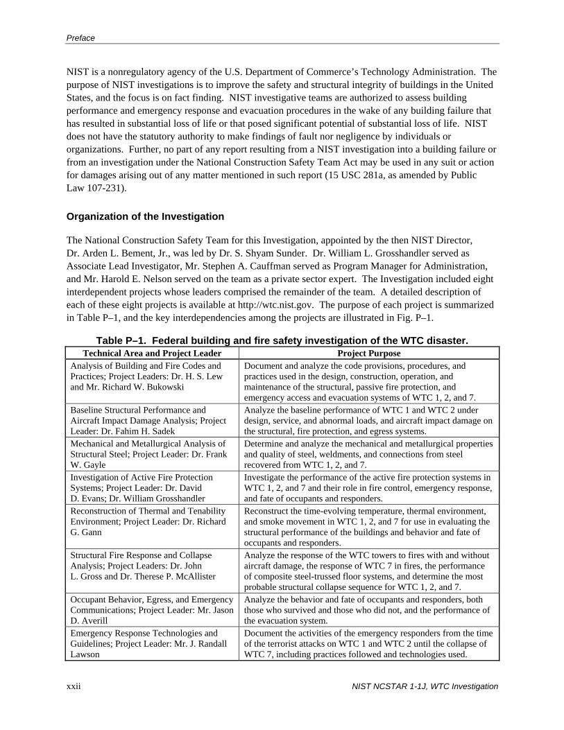
The National Construction Safety Team for this Investigation, appointed by the then NIST Director, Dr. Arden L. Bement, Jr., was led by Dr. S. Shyam Sunder. Dr. William L. Grosshandler served as Associate Lead Investigator, Mr. Stephen A. Cauffman served as Program Manager for Administration, and Mr. Harold E. Nelson served on the team as a private sector expert. The Investigation included eight interdependent projects whose leaders comprised the remainder of the team. A detailed description of each of these eight projects is available at http://wtc.nist.gov. The purpose of each project is summarized in Table P–1, and the key interdependencies among the projects are illustrated in Fig. P–1.
Table P–1. Federal building and fire safety investigation of the WTC disaster. Technical Area and Project Leader Project Purpose
Analysis of Building and Fire Codes and Practices; Project Leaders: Dr. H. S. Lew and Mr. Richard W. Bukowski
Document and analyze the code provisions, procedures, and practices used in the design, construction, operation, and maintenance of the structural, passive fire protection, and emergency access and evacuation systems of WTC 1, 2, and 7.
Baseline Structural Performance and Aircraft Impact Damage Analysis; Project Leader: Dr. Fahim H. Sadek
Analyze the baseline performance of WTC 1 and WTC 2 under design, service, and abnormal loads, and aircraft impact damage on the structural, fire protection, and egress systems.
Mechanical and Metallurgical Analysis of Structural Steel; Project Leader: Dr. Frank W. Gayle
Determine and analyze the mechanical and metallurgical properties and quality of steel, weldments, and connections from steel recovered from WTC 1, 2, and 7.
Investigation of Active Fire Protection Systems; Project Leader: Dr. David D. Evans; Dr. William Grosshandler
Investigate the performance of the active fire protection systems in WTC 1, 2, and 7 and their role in fire control, emergency response, and fate of occupants and responders.
Reconstruction of Thermal and Tenability Environment; Project Leader: Dr. Richard G. Gann
Reconstruct the time-evolving temperature, thermal environment, and smoke movement in WTC 1, 2, and 7 for use in evaluating the structural performance of the buildings and behavior and fate of occupants and responders.
Structural Fire Response and Collapse Analysis; Project Leaders: Dr. John L. Gross and Dr. Therese P. McAllister
Analyze the response of the WTC towers to fires with and without aircraft damage, the response of WTC 7 in fires, the performance of composite steel-trussed floor systems, and determine the most probable structural collapse sequence for WTC 1, 2, and 7.
Occupant Behavior, Egress, and Emergency Communications; Project Leader: Mr. Jason D. Averill
Analyze the behavior and fate of occupants and responders, both those who survived and those who did not, and the performance of the evacuation system.
Emergency Response Technologies and Guidelines; Project Leader: Mr. J. Randall Lawson
Document the activities of the emergency responders from the time of the terrorist attacks on WTC 1 and WTC 2 until the collapse of WTC 7, including practices followed and technologies used.
xxii NIST NCSTAR 1-1J, WTC Investigation

Preface
NIST WTC Investigation ProjectsNIST WTC Investigation Projects
Analysis of Steel
Structural Collapse
Evacuation
Baseline Performance
& Impact Damage
Analysis of Codes and Practices
Emergency Response
Active Fire Protection
Thermal and Tenability
Environment
Video/Photographic Records
Oral History Data
Emergency Response Records
Recovered Structural Steel
WTC Building Performance StudyRecommendations
Government, Industry, Professional, Academic Inputs
Public Inputs
Figure P–1. The eight projects in the federal building and fire safety
investigation of the WTC disaster.
National Construction Safety Team Advisory Committee
The NIST Director also established an advisory committee as mandated under the National Construction Safety Team Act. The initial members of the committee were appointed following a public solicitation. These were:
• Paul Fitzgerald, Executive Vice President (retired) FM Global, National Construction Safety Team Advisory Committee Chair
• John Barsom, President, Barsom Consulting, Ltd.
• John Bryan, Professor Emeritus, University of Maryland
• David Collins, President, The Preview Group, Inc.
• Glenn Corbett, Professor, John Jay College of Criminal Justice
• Philip DiNenno, President, Hughes Associates, Inc.
NIST NCSTAR 1-1J, WTC Investigation xxiii

Preface
• Robert Hanson, Professor Emeritus, University of Michigan
• Charles Thornton, Co-Chairman and Managing Principal, The Thornton-Tomasetti Group, Inc.
• Kathleen Tierney, Director, Natural Hazards Research and Applications Information Center, University of Colorado at Boulder
• Forman Williams, Director, Center for Energy Research, University of California at San Diego
This National Construction Safety Team Advisory Committee provided technical advice during the Investigation and commentary on drafts of the Investigation reports prior to their public release. NIST has benefited from the work of many people in the preparation of these reports, including the National Construction Safety Team Advisory Committee. The content of the reports and recommendations, however, are solely the responsibility of NIST.
Public Outreach
During the course of this Investigation, NIST held public briefings and meetings (listed in Table P–2) to solicit input from the public, present preliminary findings, and obtain comments on the direction and progress of the Investigation from the public and the Advisory Committee.
NIST maintained a publicly accessible Web site during this Investigation at http://wtc.nist.gov. The site contained extensive information on the background and progress of the Investigation.
NIST’s WTC Public-Private Response Plan
The collapse of the WTC buildings has led to broad reexamination of how tall buildings are designed, constructed, maintained, and used, especially with regard to major events such as fires, natural disasters, and terrorist attacks. Reflecting the enhanced interest in effecting necessary change, NIST, with support from Congress and the Administration, has put in place a program, the goal of which is to develop and implement the standards, technology, and practices needed for cost-effective improvements to the safety and security of buildings and building occupants, including evacuation, emergency response procedures, and threat mitigation.
The strategy to meet this goal is a three-part NIST-led public-private response program that includes:
• A federal building and fire safety investigation to study the most probable factors that contributed to post-aircraft impact collapse of the WTC towers and the 47-story WTC 7 building, and the associated evacuation and emergency response experience.
• A research and development (R&D) program to (a) facilitate the implementation of recommendations resulting from the WTC Investigation, and (b) provide the technical basis for cost-effective improvements to national building and fire codes, standards, and practices that enhance the safety of buildings, their occupants, and emergency responders.
xxiv NIST NCSTAR 1-1J, WTC Investigation
Preface
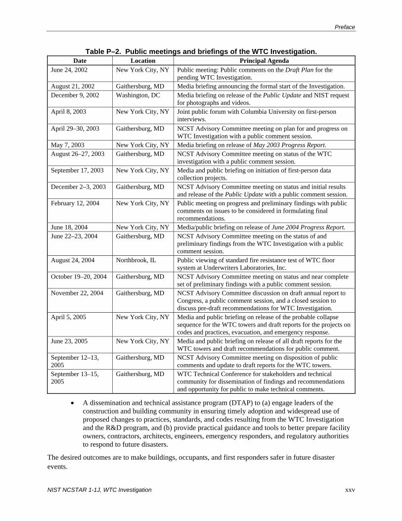
Table P–2. Public meetings and briefings of the WTC Investigation. Date Location Principal Agenda
June 24, 2002 New York City, NY Public meeting: Public comments on the Draft Plan for the pending WTC Investigation.
August 21, 2002 Gaithersburg, MD Media briefing announcing the formal start of the Investigation. December 9, 2002 Washington, DC Media briefing on release of the Public Update and NIST request
for photographs and videos. April 8, 2003
New York City, NY Joint public forum with Columbia University on first-person interviews.
April 29–30, 2003 Gaithersburg, MD NCST Advisory Committee meeting on plan for and progress on WTC Investigation with a public comment session.
May 7, 2003 New York City, NY Media briefing on release of May 2003 Progress Report. August 26–27, 2003 Gaithersburg, MD NCST Advisory Committee meeting on status of the WTC
investigation with a public comment session. September 17, 2003 New York City, NY Media and public briefing on initiation of first-person data
collection projects. December 2–3, 2003 Gaithersburg, MD NCST Advisory Committee meeting on status and initial results
and release of the Public Update with a public comment session. February 12, 2004 New York City, NY Public meeting on progress and preliminary findings with public
comments on issues to be considered in formulating final recommendations.
June 18, 2004 New York City, NY Media/public briefing on release of June 2004 Progress Report. June 22–23, 2004 Gaithersburg, MD NCST Advisory Committee meeting on the status of and
preliminary findings from the WTC Investigation with a public comment session.
August 24, 2004 Northbrook, IL Public viewing of standard fire resistance test of WTC floor system at Underwriters Laboratories, Inc.
October 19–20, 2004 Gaithersburg, MD NCST Advisory Committee meeting on status and near complete set of preliminary findings with a public comment session.
November 22, 2004 Gaithersburg, MD NCST Advisory Committee discussion on draft annual report to Congress, a public comment session, and a closed session to discuss pre-draft recommendations for WTC Investigation.
April 5, 2005 New York City, NY Media and public briefing on release of the probable collapse sequence for the WTC towers and draft reports for the projects on codes and practices, evacuation, and emergency response.
June 23, 2005 New York City, NY Media and public briefing on release of all draft reports for the WTC towers and draft recommendations for public comment.
September 12–13, 2005
Gaithersburg, MD NCST Advisory Committee meeting on disposition of public comments and update to draft reports for the WTC towers.
September 13–15, 2005
Gaithersburg, MD WTC Technical Conference for stakeholders and technical community for dissemination of findings and recommendations and opportunity for public to make technical comments.
• A dissemination and technical assistance program (DTAP) to (a) engage leaders of the construction and building community in ensuring timely adoption and widespread use of proposed changes to practices, standards, and codes resulting from the WTC Investigation and the R&D program, and (b) provide practical guidance and tools to better prepare facility owners, contractors, architects, engineers, emergency responders, and regulatory authorities to respond to future disasters.
The desired outcomes are to make buildings, occupants, and first responders safer in future disaster events.
NIST NCSTAR 1-1J, WTC Investigation xxv

Preface
National Construction Safety Team Reports on the WTC Investigation
A final report on the collapse of the WTC towers is being issued as NIST NCSTAR 1. A companion report on the collapse of WTC 7 is being issued as NIST NCSTAR 1A. The present report is one of a set that provides more detailed documentation of the Investigation findings and the means by which these technical results were achieved. As such, it is part of the archival record of this Investigation. The titles of the full set of Investigation publications are:
NIST (National Institute of Standards and Technology). 2005. Federal Building and Fire Safety Investigation of the World Trade Center Disaster: Final Report on the Collapse of the World Trade Center Towers. NIST NCSTAR 1. Gaithersburg, MD, September.
NIST (National Institute of Standards and Technology). 2008. Federal Building and Fire Safety Investigation of the World Trade Center Disaster: Final Report on the Collapse of World Trade Center 7. NIST NCSTAR 1A. Gaithersburg, MD, November.
Lew, H. S., R. W. Bukowski, and N. J. Carino. 2005. Federal Building and Fire Safety Investigation of the World Trade Center Disaster: Design, Construction, and Maintenance of Structural and Life Safety Systems. NIST NCSTAR 1-1. National Institute of Standards and Technology. Gaithersburg, MD, September.
Fanella, D. A., A. T. Derecho, and S. K. Ghosh. 2005. Federal Building and Fire Safety Investigation of the World Trade Center Disaster: Design and Construction of Structural Systems. NIST NCSTAR 1-1A. National Institute of Standards and Technology. Gaithersburg, MD, September.
Ghosh, S. K., and X. Liang. 2005. Federal Building and Fire Safety Investigation of the World Trade Center Disaster: Comparison of Building Code Structural Requirements. NIST NCSTAR 1-1B. National Institute of Standards and Technology. Gaithersburg, MD, September.
Fanella, D. A., A. T. Derecho, and S. K. Ghosh. 2005. Federal Building and Fire Safety Investigation of the World Trade Center Disaster: Maintenance and Modifications to Structural Systems. NIST NCSTAR 1-1C. National Institute of Standards and Technology. Gaithersburg, MD, September.
Grill, R. A., and D. A. Johnson. 2005. Federal Building and Fire Safety Investigation of the World Trade Center Disaster: Fire Protection and Life Safety Provisions Applied to the Design and Construction of World Trade Center 1, 2, and 7 and Post-Construction Provisions Applied after Occupancy. NIST NCSTAR 1-1D. National Institute of Standards and Technology. Gaithersburg, MD, September.
Razza, J. C., and R. A. Grill. 2005. Federal Building and Fire Safety Investigation of the World Trade Center Disaster: Comparison of Codes, Standards, and Practices in Use at the Time of the Design and Construction of World Trade Center 1, 2, and 7. NIST NCSTAR 1-1E. National Institute of Standards and Technology. Gaithersburg, MD, September.
Grill, R. A., D. A. Johnson, and D. A. Fanella. 2005. Federal Building and Fire Safety Investigation of the World Trade Center Disaster: Comparison of the 1968 and Current (2003) New
xxvi NIST NCSTAR 1-1J, WTC Investigation

Preface
York City Building Code Provisions. NIST NCSTAR 1-1F. National Institute of Standards and Technology. Gaithersburg, MD, September.
Grill, R. A., and D. A. Johnson. 2005. Federal Building and Fire Safety Investigation of the World Trade Center Disaster: Amendments to the Fire Protection and Life Safety Provisions of the New York City Building Code by Local Laws Adopted While World Trade Center 1, 2, and 7 Were in Use. NIST NCSTAR 1-1G. National Institute of Standards and Technology. Gaithersburg, MD, September.
Grill, R. A., and D. A. Johnson. 2005. Federal Building and Fire Safety Investigation of the World Trade Center Disaster: Post-Construction Modifications to Fire Protection and Life Safety Systems of World Trade Center 1 and 2. NIST NCSTAR 1-1H. National Institute of Standards and Technology. Gaithersburg, MD, September.
Grill, R. A., D. A. Johnson, and D. A. Fanella. 2005. Federal Building and Fire Safety Investigation of the World Trade Center Disaster: Post-Construction Modifications to Fire Protection, Life Safety, and Structural Systems of World Trade Center 7. NIST NCSTAR 1-1I. National Institute of Standards and Technology. Gaithersburg, MD, September.
Grill, R. A., and D. A. Johnson. 2005. Federal Building and Fire Safety Investigation of the World Trade Center Disaster: Design, Installation, and Operation of Fuel System for Emergency Power in World Trade Center 7. NIST NCSTAR 1-1J. National Institute of Standards and Technology. Gaithersburg, MD, September.
Sadek, F. 2005. Federal Building and Fire Safety Investigation of the World Trade Center Disaster: Baseline Structural Performance and Aircraft Impact Damage Analysis of the World Trade Center Towers. NIST NCSTAR 1-2. National Institute of Standards and Technology. Gaithersburg, MD, September.
Faschan, W. J., and R. B. Garlock. 2005. Federal Building and Fire Safety Investigation of the World Trade Center Disaster: Reference Structural Models and Baseline Performance Analysis of the World Trade Center Towers. NIST NCSTAR 1-2A. National Institute of Standards and Technology. Gaithersburg, MD, September.
Kirkpatrick, S. W., R. T. Bocchieri, F. Sadek, R. A. MacNeill, S. Holmes, B. D. Peterson, R. W. Cilke, C. Navarro. 2005. Federal Building and Fire Safety Investigation of the World Trade Center Disaster: Analysis of Aircraft Impacts into the World Trade Center Towers, NIST NCSTAR 1-2B. National Institute of Standards and Technology. Gaithersburg, MD, September.
Gayle, F. W., R. J. Fields, W. E. Luecke, S. W. Banovic, T. Foecke, C. N. McCowan, T. A. Siewert, and J. D. McColskey. 2005. Federal Building and Fire Safety Investigation of the World Trade Center Disaster: Mechanical and Metallurgical Analysis of Structural Steel. NIST NCSTAR 1-3. National Institute of Standards and Technology. Gaithersburg, MD, September.
Luecke, W. E., T. A. Siewert, and F. W. Gayle. 2005. Federal Building and Fire Safety Investigation of the World Trade Center Disaster: Contemporaneous Structural Steel Specifications. NIST Special Publication 1-3A. National Institute of Standards and Technology. Gaithersburg, MD, September.
NIST NCSTAR 1-1J, WTC Investigation xxvii

Preface
Banovic, S. W. 2005. Federal Building and Fire Safety Investigation of the World Trade Center Disaster: Steel Inventory and Identification. NIST NCSTAR 1-3B. National Institute of Standards and Technology. Gaithersburg, MD, September.
Banovic, S. W., and T. Foecke. 2005. Federal Building and Fire Safety Investigation of the World Trade Center Disaster: Damage and Failure Modes of Structural Steel Components. NIST NCSTAR 1-3C. National Institute of Standards and Technology. Gaithersburg, MD, September.
Luecke, W. E., J. D. McColskey, C. N. McCowan, S. W. Banovic, R. J. Fields, T. Foecke, T. A. Siewert, and F. W. Gayle. 2005. Federal Building and Fire Safety Investigation of the World Trade Center Disaster: Mechanical Properties of Structural Steels. NIST NCSTAR 1-3D. National Institute of Standards and Technology. Gaithersburg, MD, September.
Banovic, S. W., C. N. McCowan, and W. E. Luecke. 2005. Federal Building and Fire Safety Investigation of the World Trade Center Disaster: Physical Properties of Structural Steels. NIST NCSTAR 1-3E. National Institute of Standards and Technology. Gaithersburg, MD, September.
Evans, D. D., R. D. Peacock, E. D. Kuligowski, W. S. Dols, and W. L. Grosshandler. 2005. Federal Building and Fire Safety Investigation of the World Trade Center Disaster: Active Fire Protection Systems. NIST NCSTAR 1-4. National Institute of Standards and Technology. Gaithersburg, MD, September.
Kuligowski, E. D., D. D. Evans, and R. D. Peacock. 2005. Federal Building and Fire Safety Investigation of the World Trade Center Disaster: Post-Construction Fires Prior to September 11, 2001. NIST NCSTAR 1-4A. National Institute of Standards and Technology. Gaithersburg, MD, September.
Hopkins, M., J. Schoenrock, and E. Budnick. 2005. Federal Building and Fire Safety Investigation of the World Trade Center Disaster: Fire Suppression Systems. NIST NCSTAR 1-4B. National Institute of Standards and Technology. Gaithersburg, MD, September.
Keough, R. J., and R. A. Grill. 2005. Federal Building and Fire Safety Investigation of the World Trade Center Disaster: Fire Alarm Systems. NIST NCSTAR 1-4C. National Institute of Standards and Technology. Gaithersburg, MD, September.
Ferreira, M. J., and S. M. Strege. 2005. Federal Building and Fire Safety Investigation of the World Trade Center Disaster: Smoke Management Systems. NIST NCSTAR 1-4D. National Institute of Standards and Technology. Gaithersburg, MD, September.
Gann, R. G., A. Hamins, K. B. McGrattan, G. W. Mulholland, H. E. Nelson, T. J. Ohlemiller, W. M. Pitts, and K. R. Prasad. 2005. Federal Building and Fire Safety Investigation of the World Trade Center Disaster: Reconstruction of the Fires in the World Trade Center Towers. NIST NCSTAR 1-5. National Institute of Standards and Technology. Gaithersburg, MD, September.
Pitts, W. M., K. M. Butler, and V. Junker. 2005. Federal Building and Fire Safety Investigation of the World Trade Center Disaster: Visual Evidence, Damage Estimates, and Timeline Analysis. NIST NCSTAR 1-5A. National Institute of Standards and Technology. Gaithersburg, MD, September.
xxviii NIST NCSTAR 1-1J, WTC Investigation

Preface
Hamins, A., A. Maranghides, K. B. McGrattan, E. Johnsson, T. J. Ohlemiller, M. Donnelly, J. Yang, G. Mulholland, K. R. Prasad, S. Kukuck, R. Anleitner and T. McAllister. 2005. Federal Building and Fire Safety Investigation of the World Trade Center Disaster: Experiments and Modeling of Structural Steel Elements Exposed to Fire. NIST NCSTAR 1-5B. National Institute of Standards and Technology. Gaithersburg, MD, September.
Ohlemiller, T. J., G. W. Mulholland, A. Maranghides, J. J. Filliben, and R. G. Gann. 2005. Federal Building and Fire Safety Investigation of the World Trade Center Disaster: Fire Tests of Single Office Workstations. NIST NCSTAR 1-5C. National Institute of Standards and Technology. Gaithersburg, MD, September.
Gann, R. G., M. A. Riley, J. M. Repp, A. S. Whittaker, A. M. Reinhorn, and P. A. Hough. 2005. Federal Building and Fire Safety Investigation of the World Trade Center Disaster: Reaction of Ceiling Tile Systems to Shocks. NIST NCSTAR 1-5D. National Institute of Standards and Technology. Gaithersburg, MD, September.
Hamins, A., A. Maranghides, K. B. McGrattan, T. J. Ohlemiller, and R. Anleitner. 2005. Federal Building and Fire Safety Investigation of the World Trade Center Disaster: Experiments and Modeling of Multiple Workstations Burning in a Compartment. NIST NCSTAR 1-5E. National Institute of Standards and Technology. Gaithersburg, MD, September.
McGrattan, K. B., C. Bouldin, and G. Forney. 2005. Federal Building and Fire Safety Investigation of the World Trade Center Disaster: Computer Simulation of the Fires in the World Trade Center Towers. NIST NCSTAR 1-5F. National Institute of Standards and Technology. Gaithersburg, MD, September.
Prasad, K. R., and H. R. Baum. 2005. Federal Building and Fire Safety Investigation of the World Trade Center Disaster: Fire Structure Interface and Thermal Response of the World Trade Center Towers. NIST NCSTAR 1-5G. National Institute of Standards and Technology. Gaithersburg, MD, September.
Gross, J. L., and T. McAllister. 2005. Federal Building and Fire Safety Investigation of the World Trade Center Disaster: Structural Fire Response and Probable Collapse Sequence of the World Trade Center Towers. NIST NCSTAR 1-6. National Institute of Standards and Technology. Gaithersburg, MD, September.
Carino, N. J., M. A. Starnes, J. L. Gross, J. C. Yang, S. Kukuck, K. R. Prasad, and R. W. Bukowski. 2005. Federal Building and Fire Safety Investigation of the World Trade Center Disaster: Passive Fire Protection. NIST NCSTAR 1-6A. National Institute of Standards and Technology. Gaithersburg, MD, September.
Gross, J., F. Hervey, M. Izydorek, J. Mammoser, and J. Treadway. 2005. Federal Building and Fire Safety Investigation of the World Trade Center Disaster: Fire Resistance Tests of Floor Truss Systems. NIST NCSTAR 1-6B. National Institute of Standards and Technology. Gaithersburg, MD, September.
Zarghamee, M. S., S. Bolourchi, D. W. Eggers, Ö. O. Erbay, F. W. Kan, Y. Kitane, A. A. Liepins, M. Mudlock, W. I. Naguib, R. P. Ojdrovic, A. T. Sarawit, P. R Barrett, J. L. Gross, and
NIST NCSTAR 1-1J, WTC Investigation xxix
Preface
xxx NIST NCSTAR 1-1J, WTC Investigation
T. P. McAllister. 2005. Federal Building and Fire Safety Investigation of the World Trade Center Disaster: Component, Connection, and Subsystem Structural Analysis. NIST NCSTAR 1-6C. National Institute of Standards and Technology. Gaithersburg, MD, September.
Zarghamee, M. S., Y. Kitane, Ö. O. Erbay, T. P. McAllister, and J. L. Gross. 2005. Federal Building and Fire Safety Investigation of the World Trade Center Disaster: Global Structural Analysis of the Response of the World Trade Center Towers to Impact Damage and Fire. NIST NCSTAR 1-6D. National Institute of Standards and Technology. Gaithersburg, MD, September.
Averill, J. D., D. S. Mileti, R. D. Peacock, E. D. Kuligowski, N. Groner, G. Proulx, P. A. Reneke, and H. E. Nelson. 2005. Federal Building and Fire Safety Investigation of the World Trade Center Disaster: Occupant Behavior, Egress, and Emergency Communication. NIST NCSTAR 1-7. National Institute of Standards and Technology. Gaithersburg, MD, September.
Fahy, R., and G. Proulx. 2005. Federal Building and Fire Safety Investigation of the World Trade Center Disaster: Analysis of Published Accounts of the World Trade Center Evacuation. NIST NCSTAR 1-7A. National Institute of Standards and Technology. Gaithersburg, MD, September.
Zmud, J. 2005. Federal Building and Fire Safety Investigation of the World Trade Center Disaster: Technical Documentation for Survey Administration. NIST NCSTAR 1-7B. National Institute of Standards and Technology. Gaithersburg, MD, September.
Lawson, J. R., and R. L. Vettori. 2005. Federal Building and Fire Safety Investigation of the World Trade Center Disaster: The Emergency Response Operations. NIST NCSTAR 1-8. National Institute of Standards and Technology. Gaithersburg, MD, September.
McAllister, T., R. G. Gann, J. D. Averill, J. L. Gross, W. L. Grosshandler, J. R. Lawson, K. B. McGrattan, H. E. Nelson, W. M. Pitts, K. R. Prasad, F. H. Sadek. 2008. Federal Building and Fire Safety Investigation of the World Trade Center Disaster: Structural Fire Response and Probable Collapse Sequence of World Trade Center Building 7. NIST NCSTAR 1-9. National Institute of Standards and Technology. Gaithersburg, MD, November.
MacNeill, R., S. Kirkpatrick, B. Peterson, and R. Bocchieri. 2008. Federal Building and Fire Safety Investigation of the World Trade Center Disaster: Global Structural Analysis of the Response of World Trade Center Building 7 to Fires and Debris Impact Damage. NIST NCSTAR 1-9A. National Institute of Standards and Technology. Gaithersburg, MD, November.
EXECUTIVE SUMMARY
As part of the analysis of building and fire codes and standards of the National Institute of Standards and Technology (NIST) World Trade Center (WTC) Investigation, this report supports the effort to document the fuel oil distribution system located in WTC 7. Studies are under way to determine whether internal fires may have led to the collapse. A possible factor to the collapse of WTC 7 was the fuel system for emergency power located throughout the 47-story building. The purpose of this report is to document the fuel oil distribution system (including all fuel oil tanks, pumps, generators, routing of the piping, and system functions) and the associated fire protection features of the fuel oil system that existed in WTC 7 on September 11, 2001.
The document search for this report located design drawings and specifications that were submitted to and approved by the Port Authority of New York and New Jersey (PANYNJ or Port Authority) in accordance to the Building Code of the City of New York (BCNYC) requirements. In addition to the above documents, a set of certified as-built drawings for the Ambassador Construction project was located.
WTC 7 contained two independently supplied and operated fuel systems for emergency power: the Base Building system and the Salomon Brothers system. The Base Building system consisted of four sub-systems: the Silverstein sub-system (original system), the Ambassador Construction sub-system, the American Express sub-system, and the Mayor’s Office of Emergency Management sub-system. The Ambassador Construction and American Express sub-systems were supplied with fuel from the original Base Building storage tanks installed below the loading dock. The Mayor’s Office sub-system contained its own storage tank that was filled from the original system tanks. The other system (the Salmon Brothers system), was supplied by a separate set of fuel storage tanks, also located below the loading dock. The systems had differing design features with each system operating independently. The two systems combined with all of the sub-systems, contained more than an estimated 43,000 gal of fuel, assuming all tanks were filled near capacity. Since the owners had contracts with fuel delivery services to maintain the tanks full at all times, this assumption is considered reasonable.
E.1 BASE BUILDING SYSTEM
The Silverstein system was installed in 1987. The system contained two 12,000 gal capacity storage tanks located below the 1st floor loading dock. The tanks supplied no. 2 diesel fuel to a duplex fuel oil pump set located in the 1st floor Fuel Oil Pump Room situated between the west banks of passenger elevators. The pumps supplied fuel to a 275 gal capacity day tank1 in the 5th floor Generator Room, which supplied fuel to two 900 kW generators. The fuel oil return (FOR) pipes ran in parallel with the fuel oil supply (FOS) pipes returning fuel back to the day tank and storage tanks.
In 1994, the Silverstein system was modified for the Ambassador Construction project. The Base Building system was extended by tapping off the existing FOS pipe to the duplex pump set in the 1st floor
1 A day tank is a small-capacity fuel storage tank located near the generator(s) and kept full by a transfer pump from a main
tank at or below grade. The BCNYC limits fuel supplies to no more than one 275 gal (maximum) day tank on any floor above the 1st.
NIST NCSTAR 1-1J, WTC Investigation xxxi

Executive Summary
xxxii NIST NCSTAR 1-1J, WTC Investigation
Fuel Oil Pump Room. The pump supplied fuel to the engine mounted day tank (50 gal capacity) of the 125 kW generator located on the 9th floor. The FOR pipe ran back to the existing FOR at the 1st floor.
Again in 1994, the Silverstein system was modified for the American Express project. The Base Building system was extended by tapping off the existing FOS suction pipe and adding another duplex pump set in the 1st floor Fuel Oil Pump Room. A 275 gal day tank was added on the 8th floor, which supplied fuel to the 350 kW generator.
In 1999, the Silverstein system was modified for the Mayor’s Office of Emergency Management project. The system added two additional duplex pump sets. The 1st pump set was used to fill a new 6,000 gal above ground storage tank on the 1st floor. The second pump set was used to supply fuel from the new storage tank to the new 275 gal day tank and three 500 kW generators on the 7th floor.
The four Base Building sub-systems were similarly designed, but were independently operated by the fuel pump set controllers for each system. The sub-systems included many similar devices, such as anti-syphon valves, foot valves, fusible link gate valves, solenoid valves, fuel level switches, rupture basins and leak detectors, all performing specific operations. Although each sub-system was not designed exactly like the other, the four sub-systems operated and performed similarly. Each sub-system operated based on the liquid level in the day tanks. Each sub-system control panel (four total) started and stopped the respective pump set by the liquid level switch in each day tank.
The various fuel devices listed above provided increased assurance that unwanted fuel discharge would not occur. The devices listed above would have prevented, in most if not all scenarios, unwanted fuel discharge unto the floor below. The devices were installed to isolate fuel from open piping breaks, prevent backflow and drainage of fuel unto the floor below and shut off the pump set to prevent fuel flow.
E.2 SALOMON BROTHERS SYSTEM
In 1990, a second fuel oil distribution system was installed for the Salomon Brothers project. The fuel for the system was supplied by two 6,000 gal storage tanks located under the loading dock. FOS pipes ran to the duplex pump set on the 1st floor. The FOS discharge pipes ran up to the 5th floor supplying fuel to nine 1,750 kW generators. The FOS discharge pipe ended at a valve rig where the FOR pipe started and ran back to the pump set and storage tanks.
The Salomon Brothers fuel system had a similar but slightly different design than the Base Building system. Similar to the Base Building system, the pump set provided fuel from two underground storage tanks. However, there was already a day tank on the 5th floor associated with the base system and the BCNYC did not permit more than one day tank per floor. Thus, the Salomon Brothers system used a continuously pressurized fuel supply piping system without a day tank. The fuel pressure in the FOS discharge piping was maintained by a liquid level switch and back pressure regulator in the 5th floor valve rig. The liquid level switch started and stopped the pump set in accordance with the liquid level in the FOS discharge pipe. The pump was powered from the generators such that any time any one generator was running, the pump was powered.
Chapter 1 INTRODUCTION
World Trade Center (WTC) 7 collapsed on September 11, 2001. The collapse of WTC 7 is under study to determine whether the internal fires on that day were probable causes for the building collapse. A possible contributor to the fires within WTC 7 is the fuel oil distribution system for emergency power located throughout the building. As part of the WTC 7 study, it is important to know where the fuel oil distribution components were located and to understand the system performance. The purpose of this report is to document the fuel oil distribution systems (including all fuel oil tanks, pumps, generators, routing of the piping and system functions) and the associated fire protection features of the fuel oil system that existed in WTC 7 at the time of the collapse.
WTC 7, located between Vesey and Barclay streets and Washington Street West Broadway in New York City, was an air rights building constructed over the existing two-story Con Edison Substation. The 47-story building (constructed out of steel and concrete) underwent numerous modifications as tenants moved in and out of WTC 7. Certain tenants required emergency power for their operations. To accommodate specific tenant requirements, the Base Building fuel oil distribution system was modified. The original Base Building fuel system (Silverstein system) was installed in 1987. The system contained numerous components located from below grade to the 5th floor. In 1994 and 1999, the Base Building system was modified three times to accommodate tenant requirements. Many components were added and the system was extended up to the 9th floor. Also, in 1990, a second fuel oil distribution system was installed for a multi-floor tenant (Salomon Brothers). The system was installed from below grade to the 5th floor. The following chapters describe in detail the fuel oil distribution system designs, layouts, performances, and modifications.
The document search for this report located design drawings and specifications that were submitted to and approved by the Port Authority of New York and New Jersey (Port Authority) in accordance with the Building Code of the City of New York requirements. In addition to the above documents, a set of certified as-built drawings for the Ambassador Construction project was located.
Whenever work was done in the WTC buildings, a project number was assigned by the Port Authority under which all contracts, drawings, and correspondence was filed. These numbers are typically of the format W(yy)-1234 (where yy is the year initiated and 1234 is a four-digit number). This report includes these numbers as references to individual projects, and files retained by the Port Authority are identified by these numbers.
NIST NCSTAR 1-1J, WTC Investigation 1

Chapter 1
2 NIST NCSTAR 1-1J, WTC Investigation
This page intentionally left blank.
Chapter 2 FUEL OIL PROVISIONS OF THE BCNYC
The facilities of the Port Authority of New York and New Jersey (PANYNJ) are not subject to the requirements of the local building codes, although PANYNJ policy was to follow the New York City codes where applicable. The distribution system was to be designed to the provisions of the Building Code of the City of New York (BCNYC). As previously stated, the fuel oil distribution systems were installed in 1987 and 1990 with modifications occurring in 1994 and 1999. Generally, building construction is performed to the most current code provisions at the time of installation. The code provisions are often updated as technology and experience advance. However, between 1987 and 1999, the fuel oil system provisions of the BCNYC remained unchanged. Thus, a single set of code provisions can be summarized for the initial design and the subsequent modifications. The BCNYC code provisions used for the installations and modifications to the fuel oil distribution systems in World Trade Center (WTC) 7 are listed in the remaining sections of this chapter.
2.1 GENERAL REQUIREMENTS
The hydrocarbon fuel oil used shall be as classified in Reference Standards (RS) 14-3 and RS 14-12 and shall have a flashpoint not lower than 100 °F (27-827).1, 2
2.2 FUEL OIL STORAGE EQUIPMENT
All fuel oil storage tanks shall be built of steel plates or sheets, made by the open hearth or basic oxygen process (27-828(a)(1)).
Tanks shall be welded, riveted and caulked, or riveted and welded. Flanges or other pipe connections may be welded. Filler of any kind between plates shall be prohibited (27-828(a)(2)).
Tanks to be buried shall be cleaned and then coated on the outside with two coats of red lead, or equivalent. Tanks shall be further protected by a coating of hot tar, asphalt, or equivalent rust resistive material, applied at the work site. Tanks installed inside buildings above ground shall be coated with one coat of red lead, or equivalent (27-828(a)(3)).
All buried storage tanks shall be constructed of at least ¼ in. thick metal and shall be designed to withstand any external loads to which the tank may be subjected (27-828(a)(4)).
Shop fabricated storage tanks shall be installed without structural alteration (27-828(a)(5)).
All openings shall be through the top of the storage tank (27-828(a)(6)).
1 The fuel oil used in WTC 7 was no. 2 fuel oil. 2 The BCNYC references given, denoted by 27-XXX, is the new numbering system.
NIST NCSTAR 1-1J, WTC Investigation 3

Chapter 2
Tanks for no. 2 commercial grade oils need not have manholes. However, if manholes are used for such oils, the manhole covers shall be bolted and made gastight (27-828(a)(7)).
Tanks shall be located at least 7 ft, measured in the most direct manner, from any source of exposed flame unless protected as provided in 27-829(a)(2) or 27-829(a)(3) and at least 2 ft from any surface where the temperature exceeds 165 °F (27-828(a)(9)).
Cylindrical tanks, except vertical tanks above ground outside of buildings, of more than 275 gal capacity shall be constructed as follows (27-828(b)):
1. Tanks 36 in. in diameter and less – at least ¼ in. shell and ¼ in. heads.
2. Tanks 37 to 72 in. in diameter – at least ¼ in. shell and 5/16 in. heads.
3. Tanks 73 to 120 in. in diameter – at least 5/16 in. shell and 3/8 in. heads.
4. Tanks over 120 in. in diameter shall be of at least 3/8 in. steel and shall be stiffened by angle rings or equivalent members so as to retain their cylindrical form.
All oil storage tanks of 275 gal capacity or less that are not buried shall have a minimum thickness of shell and head plates of no. 10 manufacturer’s standard gauge steel plate. Storage tanks of 60 gal capacity or less shall be similarly constructed but need not be thicker than no. 14 manufacturer's standard gauge (27-828(d)).
2.3 LOCATION OF TANKS
Inside of buildings, above ground, on the lowest floor as follows (27-829(a)):
1. Storage tanks having a capacity of 550 gal or less may be installed above ground on the lowest floor of a building, provided that such tanks are mounted on adequate noncombustible supports, with the tank anchored thereto. No more than 550 gal of total storage capacity may be connected to one burner or may be installed without the protection provided in paragraph 27-829(a)(2) or 27-829(a)(3).
2. Storage tanks having a capacity of more than 550 gal but less than 1,100 gal may be installed above ground on the lowest floor of a building, provided that all portions of such tanks above the floor are completely enclosed with noncombustible construction having at least a 2 h fire resistance rating. Weep holes 1 in. in diameter shall be provided at least every 3 ft along the bottom of the enclosure unless at least 15 in. of clearance, together with access door, is provided between the tank and the enclosure.
3. Storage tanks having a capacity of 1,100 gal or more may be installed above ground on the lowest floor of a building, provided that all portions of such tanks above the floor are completely enclosed with noncombustible construction having at least a 3 h resistance rating. At least 15 in. clearance shall be provided over the tanks and on all sides between the tanks and the enclosure. A noncombustible access door, constructed so as to preserve the integrity of the fire resistive enclosure, shall be installed in the enclosure above the point where the
4 NIST NCSTAR 1-1J, WTC Investigation

Fuel Oil Provisions of the BCNYC
capacity of the enclosure below the door sill would be equal to the capacity of the largest tank installed. When the longest inside dimension of the enclosure exceeds 35 ft, access doors shall be installed at intervals not exceeding 12 ft. Columns, pipes, or similar obstructions may project into the required 15 in. of space within the enclosure, provided that access door or doors are so arranged that all portions of the enclosure are accessible for servicing.
4. The capacity of individual storage tanks in no case shall exceed 20,000 gal.
Inside of building above the lowest floor as follows (27-829(b)):
1. Fuel oil storage tanks having a capacity of 275 gal or less may be installed inside of buildings above the lowest story when provided with a 4 in. thick concrete or masonry curb, or with a metal pan of gauge equal to the gauge of the tank, completely surrounding the tank and of sufficient height to contain two times the capacity of the tank. The number of such oil storage tanks shall be limited to one per story.
2. Storage tanks having a capacity of 275 gal or less, installed above the lowest floor inside a building shall be filled by means of a transfer pump supplied from a primary storage tank located and installed as otherwise required. A separate transfer pump and piping circuit shall be provided for each storage tank installed above the lowest floor. No intermediate pumping stations shall be provided between the storage tank and the transfer pump. Appropriate devices shall be provided for the automatic and manual starting and stopping of the transfer pumps so as to prevent the overflow of oil from these storage tanks.
3. A float switch shall be provided with the curb or pan around the storage tank and shall be arranged so as to sound an alarm and stop the transfer pump in case of failure of the tank or the control in the tank. The operation of the float switch shall be tested at least once each week. An alarm bell shall be located in the same room with the tank and a visual and audible alarm shall be located in a maintenance office.
Inside of buildings, below ground as follows (27-829(c)):
1. Storage tanks having a capacity greater than 275 gal may be buried inside a building provided that the top of the tank is at least 2 ft below floor level. In lieu of 2 ft of earth over the tank, the tank may be covered by concrete flooring having the same thickness as the basement floor, but not less than 4 in. concrete and reinforced with 2 in. by 2 in. mesh of at least no. 20 U.S. standard gauge steel wire. Tanks shall be placed in firm soil and shall be surrounded by clean sand or well-tamped earth, free from ashes and other corrosive substances, and free from stones that will not pass through a 1 in. mesh. When necessary to prevent floating, tanks shall be securely anchored.
2. No tank shall be buried within 3 ft of any foundation wall or footing.
Outside of building, below ground as follows (27-829(d)):
1. Storage tanks located outside of buildings and below ground shall be buried with the top of the tank at least 2 ft below ground. Tanks shall be placed in firm soil and shall be surrounded
NIST NCSTAR 1-1J, WTC Investigation 5
Chapter 2
by clean sand or well-tamped earth, free from ashes or other corrosive substance, and free from stones that will not pass through a 1 in. mesh. When necessary to prevent floating, tanks shall be securely anchored.
2. No tank shall be buried within 3 ft of any foundation wall or footing.
2.4 PIPING
Exposed piping shall be protected against mechanical damage and shall be adequately supported with rigid metal fasteners or hangers. All pipes connected to buried tanks, except test well piping, shall be provided with double swing joints at the tank (27-830(a)(1)).
Only new wrought iron, steel, or brass pipe, or type K or heavier copper tubing, or aluminum alloy tubing, properly identified, may be used. Metal tubing when used for conveying oil shall be adequately protected. Such tubing may be installed at the burner without protection. Drawn tubing when used in domestic installations shall be of at least 3/8 in. inside diameter up to the shut-off valve at the burner. Soldered connections shall be prohibited (27-830(a)(2)).
Overflow pipes, where installed, shall not be smaller in size than the supply pipe (27-830(a)(3)).
Where a shut-off valve is installed in the discharge line from an oil pump, a relief valve shall be installed in the discharge line between the pump and the 1st shut-off valve (27-830(b)(1)).
A relief or pressure regulating valve shall be provided in the oil piping system on the heater side of the shut-off valves (27-830(b)(2)).
Relief valves shall be set to discharge at not more than one and one-half times the maximum working pressure of the system. The discharge from relief valves shall be returned to the storage tank or to the supply line. There shall be no shut-off valve in the line of relief (27-830(b)(3)).
Fuel oil heaters shall not be installed within the steam or water space of a boiler. Fuel oil heaters and the connecting piping shall be arranged to prevent oil leakage from being transmitted to the boiler. This may be accomplished by any of the following methods (27-830(c)):
1. By discarding the condensate from the heaters.
2. By using approved double tube or other approved heaters.
3. By means of a secondary hot water or steam heating system where the water or steam from the boiler has no direct contact with the oil heater.
4. By a sight tank arrangement for collecting and inspecting the condensate which is provided with a pump controlled by a hand switch for returning the condensate to the normal return system.
5. By such other method as may be permitted by the commissioner.
6 NIST NCSTAR 1-1J, WTC Investigation

Fuel Oil Provisions of the BCNYC
A vent pipe of iron or steel, without trap, draining to the tank, shall be provided for each storage tank. The lower end of the vent pipe shall not extend more than 1 in. through the top of the storage tank. Cross-connection between a vent pipe and fill pipe is prohibited (27-830(d)(1)).
Where a battery of storage tanks designed to hold the same grade of oil is installed, vent pipes may be run into a main header (27-830(d)(2)).
Vents shall be at least one and ¼ in. in diameter for storage tanks not exceeding 1,100 gal capacity and at least 2 in. in diameter for storage tanks of 1,100 gal or more except that vents for storage tanks of 60 gal capacity or less shall be at least ½ in. in diameter. Vents for tanks inside of buildings above the lowest floor shall be run into the primary storage tank vent (27-830(d)(3)).
Vent pipes shall be provided with an approved weatherproof hood having a free area of at least the pipe size area. Vent pipes shall terminate outside the building in a non-hazardous location, at least 2 ft from any building opening and not less than 2 ft nor more than 12 ft above the fill pipe terminal, unless otherwise permitted by the commissioner. If the vent pipe terminal is not visible from the fill pipe terminal location, a 1 in. tell-tale line shall be connected to the tank and shall parallel the fill pipe and terminate at the fill pipe terminal with an unthreaded end. Such tell-tale lines shall be provided with a check valve set to prevent flow of surface water to the storage tank (27-830(d)(4)).
Fill pipes shall terminate outside the buildings, with the fill pipe terminal located at or above grade, at least 2 ft from any building opening and 5 ft from any subway grating at or below the level of the fill pipe terminal. No fill pipe shall be less than 2 in. in diameter. Where there are facilities for the delivery tank truck to drive onto the premises, the fill terminal may be located elsewhere than at the curb (27-830(e)(1)).
Each storage tank shall be provided with a separate fill pipe, except that where a battery of tanks is installed containing the same grade of oil, a common fill and header pipe may be installed (27-830(e)(2)).
Where the top of the storage tank is above the fill pipe terminal, the fill pipe shall be connected to the top of the tank and provided with a shut-off valve and swing check valve both of which shall be located at the fill pipe terminal. However, the shut-off and check valves may be installed in an accessible location inside the building at or below the level of the fill pipe terminal (27-830(e)(3)).
All fill pipe terminals shall be of an approved type, and shall be provided with lugs for embedding in concrete. In lieu of lugs, a set screw or threads to fasten the terminal to the fill pipe may be used (27-830(e)(4)).
Piping from transfer pump to storage tanks above the lowest floor as follows (27-830(f)):
1. The piping from a transfer pump to storage tanks at levels above the lowest floor in buildings, the return piping, and vent piping shall comply with the applicable provisions of subdivisions 27-830(a) and 27-830(d) and shall be enclosed in a shaft constructed of 4 in. concrete or masonry having a 4 in. clearance from all pipe or pipe covering. Provision shall be made for expansion in piping without the use of expansion joints.
NIST NCSTAR 1-1J, WTC Investigation 7

Chapter 2
2. Where it is necessary to make horizontal offsets in the supply piping and pipe shafts such piping shall be enclosed in a sleeve of other piping of at least no. 10 manufacturer's standard gauge steel, two sizes larger and arranged to drain into the shaft. Horizontal piping offsets shall be further enclosed in construction having a 2 h fire resistance rating.
3. A drain pipe shall be installed at the base of shafts enclosing the supply and overflow piping. The pipe shall lead to an open sight drain or to an open sump.
4. Oil lines for tanks above the level of the lowest floor shall be seamless steel pipe of a weight not less than ASA schedule 40 with welded connections.
5. Pipe shafts shall not be penetrated by or contain other piping or ducts.
The heating of oil in storage tanks shall be by means of coils using low pressure hot water or steam, or by means of electric heaters approved for use in oil storage tanks (27-830(g)).
Where more than one storage tank is connected to a common supply line, a shut-off valve shall be provided in the supply line at each tank. Where more than one burner is connected to a supply line a shut-off valve shall be provided at each burner. Where a single tank and a single burner are installed, a shut-off valve shall be required in the supply line at the tank and another at the burner. Valves shall be brass or equivalent in corrosion and fire resistance, shall provide tight shut-off, and shall be rated at 125 psi or greater as required by the pressure in the system (27-830(h)(1)).
Where a storage tank is located so that the top of the tank is above the oil inlet to the burner or to the fuel pump, and the storage tank capacity is greater than 275 gal, the supply line to the burner shall be provided with an approved anti-syphon device. The device shall be located at the highest point in the supply line. Where an approved foot valve is used in the tank and the tank is constructed with a manhole, an anti-syphon device shall not be required (27-830(h)(2)).
The pressure in oil lines to burners located above the lowest floor of a building shall not be more than is required to circulate oil to and from the burners, and all parts of the oil system shall be capable of withstanding the maximum working pressure in that part of the system (27-830(h)(3)).
A remote control shall be provided to stop the flow of oil to any burner. Such control shall be located outside the entrance to the room in which the burner is located and as close to such entrance as practicable, except that when an outside location is impracticable, such control may be located immediately inside the room in which the burner is located, provided such location is accessible at all times. On storage tanks of 60 gal or less capacity used with manually operated burners, such remote control may be installed in the supply lines between tank and burner (27-830(h)(4)).
Pressure in a storage tank for the purpose of discharging oil shall be prohibited (27-830(h)(5)).
In systems where either steam or air is used for atomizing the oil, the oil and the atomizing supply shall be interlocked so that where the supply of either is interrupted, the supply of the other will be immediately cut off (27-830(h)(6)).
8 NIST NCSTAR 1-1J, WTC Investigation

Fuel Oil Provisions of the BCNYC
All tanks located inside buildings shall be provided with an oil level indicating device. Test wells shall be prohibited in tanks located inside of buildings. Unused tank openings shall be permanently sealed to prevent the removal of plugs or cover (27-830(i)(1)).
Oil level indicating devices shall be designed and constructed of substantial materials so that there can be no leakage of oil or oil vapor (27-830(i)(2)).
Test wells in storage tanks located outside of buildings shall be capped oil tight and kept closed when not in use (27-830(i)(3)).
2.5 CONTROLS
With each automatic burner a set of safety controls of the electric, pneumatic, hydraulic, or mechanical type shall be installed and maintained in good working order. The controls shall provide the following functions (27-831):
1. Ignition
2. Stack or combustion control
3. High temperature or pressure control
NIST NCSTAR 1-1J, WTC Investigation 9
Chapter 2
10 NIST NCSTAR 1-1J, WTC Investigation
This page intentionally left blank.

Chapter 3 BASE BUILDING DESIGN (1987)
The Base Building fuel oil system (Silverstein system) design was submitted to the Port Authority of New York and New Jersey (PANYNJ) for approval in 1987 under PANYNJ submittal number W-01437. The system was designed by the development team of:
• Owner/Developer: Silverstein Properties, Inc.
• Architect: Emery Roth & Sons, P.C.
• Structural Engineer: The Office of Irwin G. Cantor, P.C.
• Engineer: Syska & Hennessy
3.1 BASIC LAYOUT
The fuel distribution system was designed for no. 2 diesel fuel. The design started with two storage tanks located below the 1st floor loading dock located on the south side of the building (Fig. 3–1). The storage tanks were connected with a 2 in. fuel oil supply (FOS) pipe leading to a duplex fuel oil pump set located at the north wall of the 1st floor Fuel Oil Pump room which was located between the two west banks of passenger elevators. The fuel was pumped via a 2 in. FOS pipe to a 275 gal day tank located on the north wall of the 5th floor Generator Room, which was located at the west end of the south wall (Fig. 3–2). The 2 in. FOS pipe, which led to the day tank, ran vertically up a shaft near the west bank of passenger elevators. The shaft where the FOS pipe was located also contained other building utilities. The day tank supplied fuel to two emergency generators located on the east wall of the 5th floor Generator Room. A 2 in. fuel oil return (FOR) pipe, ran parallel with the FOS pipe back to the day tank. The FOR pipe continued back to the pump sets and storage tanks. An elevation diagram showing the floor locations of components is provided as Fig. 3–3.
3.2 COMPONENT DETAILS
The two Silverstein storage tanks had a capacity of 12,000 gal each. Each storage tank had a fuel fill box at grade and was specified to be constructed of fiberglass reinforced plastic.
The fuel oil pump set consisted of a strainer and two positive displacement pumps specified for 3/4 hp. The pump schedule on the drawings listed the pumps as 4.4 gpm at 3,500 rpm with a design pressure of 50 psi. Each pump had a relief valve set at 100 psi. The pump set was designed to have the lead pump start and stop automatically in response to the level controller in the day tank. A hand oil pump was also to be installed in parallel with the pump set. The hand oil pump was specified as a multiple-acting oscillating force type pump with a capacity of 30 gpm at not more than 50 double strokes per minute. The FOS discharge piping also contained a check valve.
NIST NCSTAR 1-1J, WTC Investigation 11

Chapter 3
The 275 gal day tank was equipped with a high-level alarm, pump on, pump off, and low-level alarm. The tank was specified to be equipped with a double-throw selector switch for active pump selection. Level controls were to automatically start the pump set at the low level and stop the pump set at the high-level settings to maintain oil supply in the day tank. Alarm actuators were programmed to sound an alarm when the oil level in the tank fell below the low-level pump cut-in setting or rose above the high-level pump cutout setting. The day tank supply line (FOS discharge line) had a solenoid valve installed. The day tank sat inside a 550 gal capacity collecting pan. The collecting pan contained an alarm device to detect fuel and a drainpipe with a capped off valve. The collecting pan had a high-level pump cutoff and alarm set to automatically stop the pump set and sound an alarm when the oil reached the high-level setting in the collecting pan. The day tank also had a fuel oil vent pipe that terminated outside of the south Generator Room wall.
The two generators were specified for 900 kW, 460 V, 3 phase and equipped with automatic engine starting controls and alarms. Alarm indicators included:
• Low and high oil pressure
• High cooling water temperature
• Low warm-up jacket water temperature
• Day tank low and high fuel level
• Low battery voltage
• Over speed
• Failure to start
The Silverstein FOS and FOR pipes were contained in an outer pipe that protected the fuel pipe. The outer pipe was joined with welded flanges and oil tight gaskets. The outer pipe was covered with 2 in. calcium silicate (or equivalent) to provide a 2 h fire resistance rating. The outer pipe contained 1 in. couplings with inspection plugs located approximately 50 ft on center. The outer pipe contained inner pipe support spiders approximately 10 ft on center. The high points of the FOS suction pipe were equipped with anti-siphon valves.
3.3 FIRE PROTECTION
Sprinkler drawings indicate that the Mechanical Equipment Rooms were to be protected with a wet pipe sprinkler system designed for ordinary hazard group I with a minimum density of 0.16 gpm/ft2 over 1,500 ft2 with a maximum spacing of 130 ft2 per head.
Sprinkler drawings indicate that the Fuel Oil Pump Room was to be protected with a dry pipe sprinkler system designed for ordinary hazard group III with a minimum density of 0.21 gpm/ft2 over the entire room with a maximum spacing of 130 ft2 per head. The drawings show a sprinkler main entering into the room but hydraulic design criteria and the location of sprinkler heads are not shown. The 5th floor Generator Room did not contain an automatic fire suppression system.
12 NIST NCSTAR 1-1J, WTC Investigation
Base Building Design (1987)
The drawings do not indicate the construction type of the Fuel Oil Pump Room. The door had a fire rating of 1½ h.
The Generator Room appears to have been constructed of 8 in. solid concrete block. The fire rating of the walls was not indicated on the drawings. The fire rating of the Generator Room doors was 1½ h.
3.4 REFERENCES
Emery Roth & Sons, P.C. 1986. “7 World Trade Center.” Architectural Drawings (1, 3, 6, 11).
Emery Roth & Sons, P.C. 1987. “7 World Trade Center.” Electrical Drawings (E-3, E-11, E-23, E-24). January 30.
Emery Roth & Sons, P.C. 1987. “7 World Trade Center.” Fire Protection Drawings (PFP-1, PFP-2). January 30.
Emery Roth & Sons, P.C. 1987. “7 World Trade Center.” Mechanical Drawings (H-2, H-6, H-22, H-24, H-25).
Port Authority of New York and New Jersey. 1997. Port Authority Facility Condition Survey Program, 7 World Trade Center. April.
Silverstein Properties. Equipment and Maintenance List, 7 World Trade Center.
Syska & Hennessy, Mechanical and Electrical Systems. 1984. 7 World Trade Center Specifications, Section 15520 – Emergency Diesel Generator Systems. October 29.
Syska & Hennessy, Mechanical and Electrical Systems. 1984. 7 World Trade Center Specifications, Section 16007 – Diesel Engine Driven Standby Power Plant. October 22.
NIST NCSTAR 1-1J, WTC Investigation 13

Chapter 3
CORE
& RETURN RISERSFUEL OIL SUPPLY
FUEL OIL
STORAGE TANKS(BELOW GRADE)
PUMP SET
Figure 3–1. Base Building 1st floor fuel oil distribution plan.
CORE
FUEL OIL SUPPLY& RETURN RISERSEMERGENCY GENERATORS
DAY TANK
Figure 3–2. Base Building 5th floor fuel oil distribution plan.
14 NIST NCSTAR 1-1J, WTC Investigation

Base Building Design (1987)
1ST FLOOR
2ND FLOOR
3RD FLOOR
4TH FLOOR
5TH FLOOR
STORAGE TANKS
PUMP SET
DAY TANK
EMERGENCY GENERATOR(TYP. OF 2)
6TH FLOOR
7TH FLOOR
8TH FLOOR
9TH FLOOR
Figure 3–3. Base Building section plan of fuel oil distribution components.
NIST NCSTAR 1-1J, WTC Investigation 15

Chapter 3
16 NIST NCSTAR 1-1J, WTC Investigation
This page intentionally left blank.
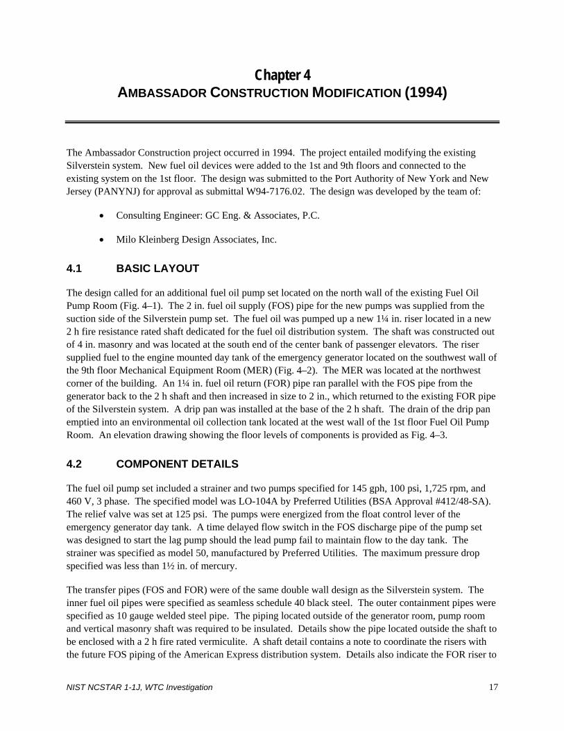
Chapter 4 AMBASSADOR CONSTRUCTION MODIFICATION (1994)
The Ambassador Construction project occurred in 1994. The project entailed modifying the existing Silverstein system. New fuel oil devices were added to the 1st and 9th floors and connected to the existing system on the 1st floor. The design was submitted to the Port Authority of New York and New Jersey (PANYNJ) for approval as submittal W94-7176.02. The design was developed by the team of:
• Consulting Engineer: GC Eng. & Associates, P.C.
• Milo Kleinberg Design Associates, Inc.
4.1 BASIC LAYOUT
The design called for an additional fuel oil pump set located on the north wall of the existing Fuel Oil Pump Room (Fig. 4–1). The 2 in. fuel oil supply (FOS) pipe for the new pumps was supplied from the suction side of the Silverstein pump set. The fuel oil was pumped up a new 1¼ in. riser located in a new 2 h fire resistance rated shaft dedicated for the fuel oil distribution system. The shaft was constructed out of 4 in. masonry and was located at the south end of the center bank of passenger elevators. The riser supplied fuel to the engine mounted day tank of the emergency generator located on the southwest wall of the 9th floor Mechanical Equipment Room (MER) (Fig. 4–2). The MER was located at the northwest corner of the building. An 1¼ in. fuel oil return (FOR) pipe ran parallel with the FOS pipe from the generator back to the 2 h shaft and then increased in size to 2 in., which returned to the existing FOR pipe of the Silverstein system. A drip pan was installed at the base of the 2 h shaft. The drain of the drip pan emptied into an environmental oil collection tank located at the west wall of the 1st floor Fuel Oil Pump Room. An elevation drawing showing the floor levels of components is provided as Fig. 4–3.
4.2 COMPONENT DETAILS
The fuel oil pump set included a strainer and two pumps specified for 145 gph, 100 psi, 1,725 rpm, and 460 V, 3 phase. The specified model was LO-104A by Preferred Utilities (BSA Approval #412/48-SA). The relief valve was set at 125 psi. The pumps were energized from the float control lever of the emergency generator day tank. A time delayed flow switch in the FOS discharge pipe of the pump set was designed to start the lag pump should the lead pump fail to maintain flow to the day tank. The strainer was specified as model 50, manufactured by Preferred Utilities. The maximum pressure drop specified was less than 1½ in. of mercury.
The transfer pipes (FOS and FOR) were of the same double wall design as the Silverstein system. The inner fuel oil pipes were specified as seamless schedule 40 black steel. The outer containment pipes were specified as 10 gauge welded steel pipe. The piping located outside of the generator room, pump room and vertical masonry shaft was required to be insulated. Details show the pipe located outside the shaft to be enclosed with a 2 h fire rated vermiculite. A shaft detail contains a note to coordinate the risers with the future FOS piping of the American Express distribution system. Details also indicate the FOR riser to
NIST NCSTAR 1-1J, WTC Investigation 17
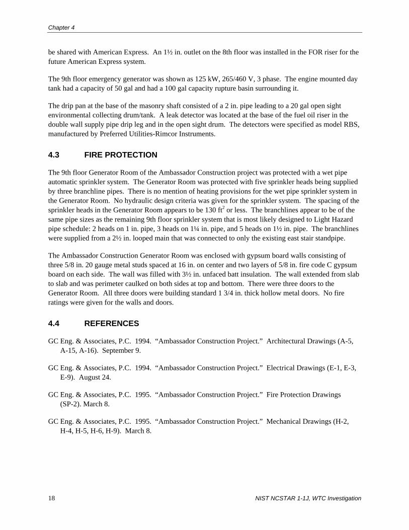
Chapter 4
be shared with American Express. An 1½ in. outlet on the 8th floor was installed in the FOR riser for the future American Express system.
The 9th floor emergency generator was shown as 125 kW, 265/460 V, 3 phase. The engine mounted day tank had a capacity of 50 gal and had a 100 gal capacity rupture basin surrounding it.
The drip pan at the base of the masonry shaft consisted of a 2 in. pipe leading to a 20 gal open sight environmental collecting drum/tank. A leak detector was located at the base of the fuel oil riser in the double wall supply pipe drip leg and in the open sight drum. The detectors were specified as model RBS, manufactured by Preferred Utilities-Rimcor Instruments.
4.3 FIRE PROTECTION
The 9th floor Generator Room of the Ambassador Construction project was protected with a wet pipe automatic sprinkler system. The Generator Room was protected with five sprinkler heads being supplied by three branchline pipes. There is no mention of heating provisions for the wet pipe sprinkler system in the Generator Room. No hydraulic design criteria was given for the sprinkler system. The spacing of the sprinkler heads in the Generator Room appears to be 130 ft2 or less. The branchlines appear to be of the same pipe sizes as the remaining 9th floor sprinkler system that is most likely designed to Light Hazard pipe schedule: 2 heads on 1 in. pipe, 3 heads on 1¼ in. pipe, and 5 heads on 1½ in. pipe. The branchlines were supplied from a 2½ in. looped main that was connected to only the existing east stair standpipe.
The Ambassador Construction Generator Room was enclosed with gypsum board walls consisting of three 5/8 in. 20 gauge metal studs spaced at 16 in. on center and two layers of 5/8 in. fire code C gypsum board on each side. The wall was filled with 3½ in. unfaced batt insulation. The wall extended from slab to slab and was perimeter caulked on both sides at top and bottom. There were three doors to the Generator Room. All three doors were building standard 1 3/4 in. thick hollow metal doors. No fire ratings were given for the walls and doors.
4.4 REFERENCES
GC Eng. & Associates, P.C. 1994. “Ambassador Construction Project.” Architectural Drawings (A-5, A-15, A-16). September 9.
GC Eng. & Associates, P.C. 1994. “Ambassador Construction Project.” Electrical Drawings (E-1, E-3, E-9). August 24.
GC Eng. & Associates, P.C. 1995. “Ambassador Construction Project.” Fire Protection Drawings (SP-2). March 8.
GC Eng. & Associates, P.C. 1995. “Ambassador Construction Project.” Mechanical Drawings (H-2, H-4, H-5, H-6, H-9). March 8.
18 NIST NCSTAR 1-1J, WTC Investigation
Ambassador Construction Modification (1994)
CORE
PUMP SETFUEL OIL
FUEL OIL SUPPLY& RETURN RISERS
Figure 4–1. First floor fuel oil distribution plan after the Ambassador Construction
modification.
CORE
EMERGENCY GENERATORWITH ENGINE MOUNTED TANK
& RETURN RISERSFUEL OIL SUPPLY
Figure 4–2. Ninth floor fuel oil distribution plan after the Ambassador Construction
modification.
NIST NCSTAR 1-1J, WTC Investigation 19

Chapter 4
1ST FLOOR
3RD FLOOR
4TH FLOOR
5TH FLOOR
2ND FLOOR
6TH FLOOR
7TH FLOOR
8TH FLOOR
9TH FLOOR
NEW EMERGENCY GENERATORWITH ENGINE MOUNTED TANK
NEW PUMP SET
DISTRIBUTION SYSTEMEXISTING BASE BULDING
DISTRIBUTION SYSTEMEXISTING SALOMON BROTHERS
Figure 4–3. Section plan of fuel oil distribution components after the Ambassador
Construction modification.
20 NIST NCSTAR 1-1J, WTC Investigation
Chapter 5 AMERICAN EXPRESS MODIFICATION (1994)
The American Express modification occurred at or around the same time as the Ambassador Construction project in 1994. Provisions for the American Express fuel oil distribution system are noted in the Ambassador Construction drawings. The project included fuel oil distribution changes to the Silverstein system located on the 1st, 7th, and 8th floors. The design was submitted to the Port Authority of New York and New Jersey (PANYNJ) for approval under PANYNJ submitted number W93-7233. The project team included:
• Architect: Gensler & Associates Architects
• Mechanical/Electrical Consulting Engineer: Lehr Associates
5.1 BASIC LAYOUT
The American Express design started in the 1st floor Fuel Oil Pump Room by tapping into the existing 2 in. fuel oil supply (FOS) suction pipe of the Silverstein system. The new 2 in. FOS pipe supplied fuel to a new pump set located at the west wall of the 1st floor pump room (Fig. 5–1). A new 2 in. FOS pipe ran up the same 4 in. masonry shaft as the Ambassador Construction project to a day tank located in the 8th floor (Fig. 5–3) Generator Room on the west side of the building. The day tank was connected to the emergency generator. A 2 in. fuel oil return (FOR) pipe from the day tank penetrated the Generator Room floor and then continued back horizontally to the masonry shaft on the 7th floor (Fig. 5–2). The FOR pipe went back to the existing 2 in. FOR pipe located in the 1st floor Fuel Oil Pump Room. An elevation diagram showing the floor location of components is provided as Fig. 5–4.
5.2 COMPONENT DETAILS
The American Express fuel oil pump set consisted of a strainer and two ½ hp pumps. The drawings specified Preferred Utilities pump Model 02715 or approved equal (BSA #1396-24SA) with a rating of 170 gph at 100 psi. The pumps had ½ in. relief valves piped back to the existing FOR pipe. A fuel oil pump controller was located at the day tank to automatically and manually start/stop the pump set. The controller was equipped with a high-level probe to automatically stop pumps and sound an alarm to prevent an overflow.
The pipes were specified as schedule 40 seamless. All horizontal piping above the lowest level was installed in an outer containment pipe two sizes larger than the inner fuel oil pipe. The horizontal pipes were installed in a 2 h fire resistance rated enclosure.
The day tank had a capacity of 275 gal. The day tank was set in a rupture basin that contained leak detection, which was to sound an alarm when liquid was detected.
The eight-floor emergency generator was shown as 350 kW, 438 kVa, and 60 Hz.
NIST NCSTAR 1-1J, WTC Investigation 21

Chapter 5
A detail in the drawings indicated a 14 gauge pan to be installed at the base of the masonry shaft. The pan was connected by a 1½ in. drainpipe to a 50 gal open basin with a liquid detector. The basin was shown at the east wall of the 1st floor Fuel Oil Pump Room.
5.3 FIRE PROTECTION
The American Express Generator Room on the 8th floor was protected by an automatic wet pipe sprinkler system. The hydraulic design criteria for the floor indicates a system design for Light Hazard with a density of 0.10 gpm/1,500 ft2. Hydraulic calculations were performed with a sprinkler head K factor of 5.62 and a sprinkler head spacing of 120 ft2. There were five sprinkler heads in the Generator Room supplied by three branchline pipes. The sprinklers in the Generator Room were spaced at approximately 80 ft2. The branchline sizes of the Generator Room were sized to match the calculated sizes of the remaining office floor: 1 head on 1 in. pipe, 3 heads on 1¼ in. pipe, and 5 heads on 1½ in. pipe. The brachlines were supplied from a 2½ in. looped main that was connected to only the existing east stair standpipe.
It is not clear which partition type was used to enclose the Generator Room. Drawing 8A2.1 indicates that all walls were to be Type A, unless otherwise noted. Type A walls were gypsum walls that consisted of 2½ in. metal studs spaced at 16 in. on center and one layer of 5/8 in. gypsum board on each side. The gypsum board appears to have been extended only to the ceiling, not to the underside of the structure. Type A appears to have no fire resistive rating. It is apparent that the walls around the Generator Room are thicker than the standard Type A walls on drawing 8A2.1. Also, looking more closely at the drawing, small hash marks are apparent along the Generator Room walls suggesting that a wall type other than Type A was to be used in the design. Drawing A9.4 indicates a wall Type H that may have been used for the Generator Room walls. Type H is a 2 h rated wall consisting of 6 in. concrete masonry unit. filled with grout and one layer of 5/8 in. gypsum board on 7/8 in. hat channel on one side of the wall. The Type H detail on A9.4 also shows a 4 in. high concrete pad adjacent to the wall. The concrete pad further suggests that a Type H wall was used for the Generator Room since the generator sat on a concrete pad against the wall. The double doors to the Generator Room were fire rated for 1½ h and had smoke seals at the sills.
5.4 REFERENCES
Gensler & Associates Architects. 1994. “American Express 7 World Trade Center, NYC.” Architectural Drawings (AO.3, A9.1, A9.2, A9.4, 8A2.1). March 14.
Gensler & Associates Architects. 1994. “American Express 7 World Trade Center, NYC.” Electrical Drawings (EO.3). July 26.
Gensler & Associates Architects. 1994. “American Express 7 World Trade Center, NYC.” Fire Protection Drawings (8-SP1.2). March 16.
Gensler & Associates Architects. 1995. “American Express 7 World Trade Center, NYC.” Mechanical Drawings (MO.4.2, 7-M1.1, 8-M1.2). February 24.
22 NIST NCSTAR 1-1J, WTC Investigation

American Express Modification (1994)
CORE
& RETURN RISERSFUEL OIL SUPPLY
PUMP SETFUEL OIL
Figure 5–1. First floor fuel oil distribution plan after the American Express modification.
CORE
FUEL OIL SUPPLY& RETURN RISERS
FUEL OIL RETURNRISER
Figure 5–2. Seventh floor fuel oil distribution plan after the American Express
modification.
CORE
RISERFUEL OIL SUPPLY
EMERGENCY GENERATOR
DAY TANK
RISERFUEL OIL RETURN
Figure 5–3. Eighth floor fuel oil distribution plan after the American Express
modification.
NIST NCSTAR 1-1J, WTC Investigation 23
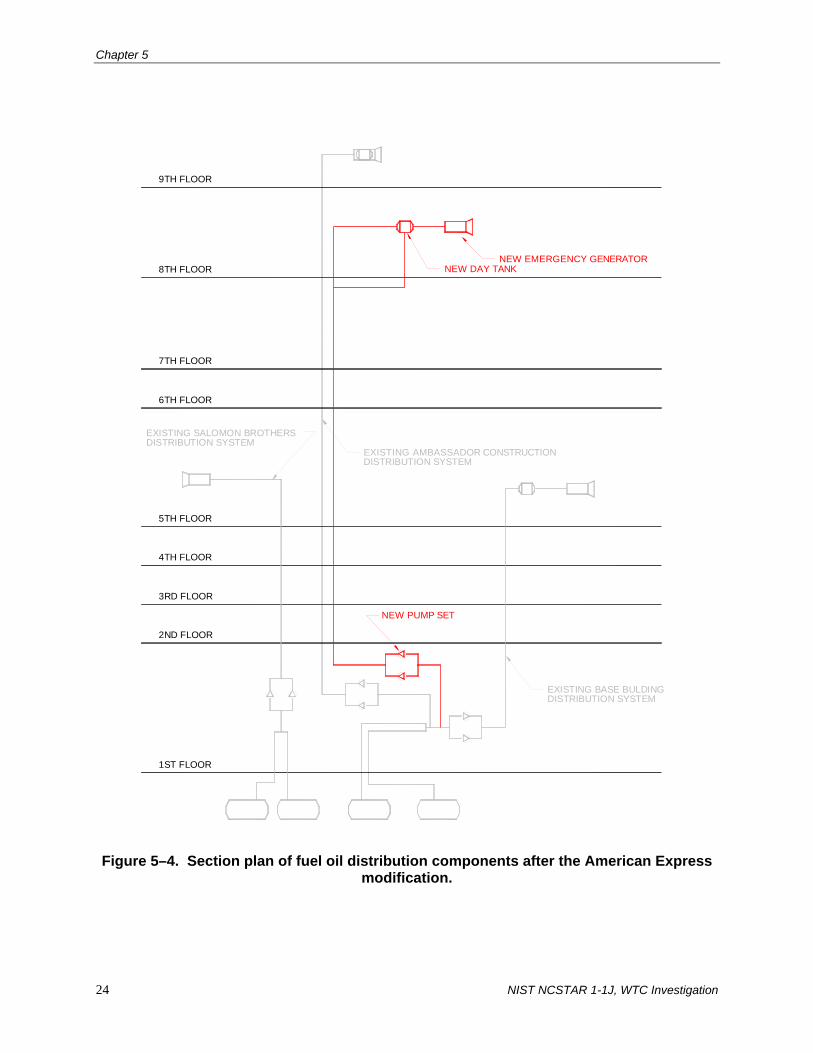
Chapter 5
24 NIST NCSTAR 1-1J, WTC Investigation
1ST FLOOR
4TH FLOOR
3RD FLOOR
2ND FLOOR
6TH FLOOR
5TH FLOOR
EXISTING BASE BULDINGDISTRIBUTION SYSTEM
9TH FLOOR
8TH FLOOR
7TH FLOOR
DISTRIBUTION SYSTEMEXISTING AMBASSADOR CONSTRUCTION
NEW EMERGENCY GENERATORNEW DAY TANK
NEW PUMP SET
DISTRIBUTION SYSTEMEXISTING SALOMON BROTHERS
Figure 5–4. Section plan of fuel oil distribution components after the American Express
modification.
Chapter 6 MAYOR’S OFFICE OF EMERGENCY MANAGEMENT
MODIFICATION (1999)
In 1999, the last modification to the Silverstein system was performed to accommodate the Mayor’s Office of Emergency Management (OEM) in World Trade Center (WTC) 7. The design of the fuel oil distribution system was very demanding. The specifications required a design to self-support OEM operations for at least one week. Modifications were made at the 1st and 7th floors. The design was submitted to the Port Authority of New York and New Jersey (PANYNJ or Port Authority) for approval under PANYNJ submittal number W98-7134. The modification was performed by the following team:
• Architect: Swanke Hayden Connell
• Mechanical Engineer: Cosentini Associates, L.L.P.
• Structural Engineer: The Cantor Seinuk Group, P.C.
• Construction Manager: Ambassador Construction Co., Inc.
6.1 BASIC LAYOUT
A fill pump set was connected to the suction side of the existing pump set in the existing Fuel Oil Pump Room (Fig. 6–1). The Fuel Oil Pump Room contained an alarm drum (catch basin for fuel leakage) with leak detection. An 1¼ in. fuel oil supply (FOS) pipe was connected from the fill pump set to a new storage tank located in the existing Televator Room (storage room for battery operated Genie boom lift) between the center and east passenger elevator banks on the 1st floor. An 1¼ in. FOS pipe was run back from the storage tank to an additional transfer pump set in the Fuel Oil Pump Room. From the transfer pump set, a 1¼ in. FOS pipe was connected to the existing FOS riser (it is unclear which existing riser was being referred to, although drawings reference the existing riser being previously approved in submittal number 94-7176 to the PANYNJ). From the 7th floor FOS existing riser, a new 1¼ in. FOS pipe was connected to a day tank at the north wall of the 7th floor Generator Room located on the south side of the building (Fig. 6–2). The Generator Room was classified as Building Code of the City of New York (BCNYC), D-2 Industrial (Low Hazard). The day tank connected three emergency generators using 1¼ in. FOS pipes. A 1½ in. fuel oil return pipe ran from the generators back to the day tank. An elevation diagram showing the floor location of components is provided as Fig. 6–3.
The addition of the new storage tank mandated a fire separation from the existing Televator Room. The separation was accomplished by creating an isolated mezzanine that supported the new storage tank in the Televator Room.
NIST NCSTAR 1-1J, WTC Investigation 25

Chapter 6
6.2 COMPONENT DETAILS
The fill pump set consisted of a strainer and a pair of 2 hp pumps specified for 2,000 gph, 1,140 rpm, 50 psi total head, 125 psi design pressure, 460 V, 3 phase. The pump was specified as LO-207, manufactured by Preferred Utilities. A relief valve was installed in the FOS discharge pipe. The pump was electrically interlocked with the existing transfer pumps to prevent simultaneous operation.
The transfer pump set consisted of a strainer and a pair of 3/4 hp pumps specified for 700 gph, 50 psi total head, 125 psi design pressure, 460 V, 3 phase. The pump was specified as LO-203, manufactured by Preferred Utilities. A relief valve was installed in the FOS discharge pipe. On a drop in the fuel level below the low level, the lead pump started and stopped when it reached the high level. Should the lead pump fail to supply sufficient flow to the day tank, the fluid level would drop to low-low level control and start the lag pump and sound an alarm. The lag pump was to stop when the level reached high-level control. An alarm was designed to sound at a high-high level.
All fuel oil pipes outside of the Fuel Oil Pump Room and Fuel Oil Tank Room were 10 gauge conduit and in a 2 h fire rated enclosure. A swing check valve was installed in the supply line of the pump. An anti-siphon valve was installed at the high points of the FOS suction pipe.
The alarm drum in the Fuel Oil Pump Room had a capacity of 50 gal and contained a leak detection assembly model TG-EL-D3 manufactured by Preferred Utilities.
The OEM day tank had a capacity of 275 gal and contained a 550 gal rupture basin. The day tank was supplied with two high-level switches wired in-line for safety. If the 1st switch failed to shut down the transfer pump, the second switch’s contact was to open and, in turn, shut down the transfer pump, close the solenoid valve and alarm the Building Management System.
The three 7th floor emergency generators were specified as 500 kW, 625 kVA, 480/277 V, 3 phase. A safety interlock was installed to prevent operation of the emergency generator if discharge plenum access was open for service or inspection. The emergency generators were equipped with alarms for in operation, low starting batteries, and emergency shutdown.
The OEM fuel oil storage tank had a capacity of 6,000 gal. The tank was equipped with alarms for low-level, high-level, and leakage/rupture. A solenoid valve was installed in the FOS discharge piping close to the tank. The tank sat on a new structure in the Televator Room constructed specifically for the new storage tank. The new structure was of 4 h fire rated construction and was completely enclosed, with exception to an access hatch. Documentation of the submittal to the PANYNJ indicates that the location, design, and protection of the storage tank were a major issue with the Port Authority, mostly related to an original request to locate the tank on the 7th floor near the generator. This request was denied by New York City Fire Department because the BCNYC does not permit storage tanks above the 1st floor except for small (>275 gal) day tanks. Some important facts that come from the PANYNJ submittal documents include designating the Fuel Oil Tank Room as BCNYC occupancy classification A with the Televator Room below as occupancy classification B-2-Storage. The Fuel Oil Tank Room was to have retaining walls and curbs for leakage.
26 NIST NCSTAR 1-1J, WTC Investigation

Mayor’s OEM Modification (1999)
6.3 FIRE PROTECTION
The 7th floor OEM Generator Room did not contain a suppression system but contained smoke detectors. All of the existing sprinkler piping and heads were removed under the scope of the project. The new 1st floor Fuel Oil Tank Room was protected with an Inergen System. The modification project included adding sprinkler coverage to the Televator Room below. The sprinkler system for the Televator Room was designed to high hazard with a maximum spacing of 100 ft2 per head. The sprinkler heads were spaced at 168 ft2 per head. The modification project also included removing the existing sprinkler heads and branchlines from the Fuel Oil Tank Room. Although sprinkler lines were removed, standpipe and hose rack piping remained in the Fuel Oil Tank Room. All of the electrical devices in the Fuel Oil Tank Room were explosion proof, suitable for BCNYC hazardous location classification Class 1, Division 1, Group C.
As previously mentioned, the Fuel Oil Tank Room was enclosed in a 4 h fire rated construction. The walls were constructed of 8 in. concrete masonry unit. The tops of the walls were installed with Thermafiber and sealant on both sides.
The Generator Room was enclosed in 2 h fire rated construction consisting of three 5/8 in., 25 gauge metal studs spaced at 16 in. on center and had three layers of 5/8 in. gypsum board on both sides. The gypsum board inside was water resistant. An 8 in. concrete curb was constructed at the perimeter of the Generator Room. The door to the Generator Room was fire rated for 1½ h.
6.4 REFERENCES
Swanke Hayden Connell Ltd. 1998. “Mayor’s Office of Emergency Management, 7 World Trade Center Specification Manual.” April 6.
Swanke Hayden Connell Ltd. 1999. “Mayor’s Office of Emergency Management, 7 WTC NYC, NY.” Architectural Drawings (A-1-1). August 23.
Swanke Hayden Connell Ltd. 1998. “Mayor’s Office of Emergency Management, 7 WTC NYC, NY.” Electrical Drawings (E1.01, E1.07, E3.01, E6.01). September 25.
Swanke Hayden Connell Ltd. 1998. “Mayor’s Office of Emergency Management, 7 WTC NYC, NY.” Fire Protection Drawings (FP1.01, FP2.07). September 25.
Swanke Hayden Connell Ltd. 1999. “Mayor’s Office of Emergency Management, 7 WTC NYC, NY.” Mechanical Drawings (M1.01, M1.07, M4.01). March 29.
NIST NCSTAR 1-1J, WTC Investigation 27

Chapter 6
COREFILLPUMP SET
TRANSFERPUMP SET
STORAGE TANK
Figure 6–1. First floor fuel oil distribution plan after the OEM modification.
CORE
DAY TANK
EMERGENCYGENERATORS
Figure 6–2. Seventh floor fuel oil distribution plan after the OEM modification.
28 NIST NCSTAR 1-1J, WTC Investigation

Mayor’s OEM Modification (1999)
1ST FLOOR
EXISTING AMBASSADOR CONSTRUCTIONDISTRIBUTION SYSTEM
4TH FLOOR
3RD FLOOR
2ND FLOOR
6TH FLOOR
5TH FLOOR
7TH FLOOR
DISTRIBUTION SYSTEMEXISTING BASE BULDING
8TH FLOOR
9TH FLOOR
DISTRIBUTION SYSTEMEXISTING AMERICAN EXPRESS
NEW FILLPUMP SET
NEW TRANSFERPUMP SET
NEW STORAGETANK
GENERATORNEW EMERGENCY
NEW DAY TANK
(TYP. OF 3)
DISTRIBUTION SYSTEMEXISTING SALOMON BROTHERS
EXISTING RISERTIE INTO
RISERFROM EXISTING
Figure 6–3. Section plan of fuel oil distribution components after the OEM modification.
NIST NCSTAR 1-1J, WTC Investigation 29

Chapter 6
30 NIST NCSTAR 1-1J, WTC Investigation
This page intentionally left blank.

Chapter 7 SALOMON BROTHERS ADDITION (1990)
In 1990, Salomon Brothers added a new fuel oil distribution system, independent of the Base Building system of World Trade Center (WTC) 7. The new fuel oil distribution system contained components below the loading dock, the 1st floor and the 5th floor with vertical piping in between. The design was submitted to the Port Authority of New York and New Jersey (PANYNJ) for approval as either PANYNJ submittal number W-7004 or W-7005. The design team consisted of:
• Architect/Engineer: Skidmore, Owings & Merrill
• Mechanical/Electrical Engineer: Flack & Kurtz
• Structural Engineer: Office of Irwin G. Cantor, P.C.
7.1 BASIC LAYOUT
The fuel oil distribution system started with two storage tanks located beneath the loading dock just west of the existing Silverstein storage tanks (Fig. 7–1). A 3 in. fuel oil supply (FOS) pipe ran to a Fuel Oil Pump set located in a dedicated enclosure at the southeast corner of the existing Fire Pump Room located at the southwest corner of the building. An emergency fuel oil fill and return line was run from the pump set towards the central bank of passenger elevators and terminated. The pump set was connected to nine emergency generators via a 2½ in. FOS pipe. The FOS vertical riser was located just north of the pump set. The emergency generators were located throughout the 5th floor (Fig. 7–2). Four generators were located at the northeast corner of the building. Two generators were located at the northwest corner of the building. Three generators were located in the existing Generator Room next to the two existing generators of the Silverstein system. The 2½ in. FOS pipe terminated at just beyond the last generator in the northeast corner and then a 2½ in. fuel oil return (FOR) pipe returned back to the storage tanks. An elevation drawing showing the floor location of components is provided as Fig. 7–3.
7.2 COMPONENT DETAILS
The two fuel oil storage tanks each had a capacity of 6,000 gal. They were of fiberglass construction and each was provided with a vent whistle alarm.
The pump set consisted of a strainer and two 7½ hp pumps specified for 70 gpm, 50 psi total head, 1,150 rpm, 460 V, 3 phase. The specified model was 43D275 manufactured by Preferred Utilities.
The 3 in. FOS suction pipe from the storage tanks to the pump set was run underground. The 2½ in. emergency FOS and FOR pipe from the pump set to the various generators were of the double walled construction type previously mentioned throughout the report. Calcium Silicate was used to provide the 2 h fire resistance rating.
NIST NCSTAR 1-1J, WTC Investigation 31
Chapter 7
The nine emergency generators were specified as 1,750 kW.
The end of the FOS pipe and beginning of the FOR pipe at the 5th floor contained a valve rig in a leak proof box. The valve rig consisted of a backpressure regulator, gauges, and by-pass line. A liquid level switch was also installed in the vicinity. The liquid level switch was a model L6 EPB-B-S-3-H manufactured by Dwyer. The liquid level switch was wired to the pump relay.
7.3 FIRE PROTECTION
WTC 7 was sprinklered except for mechanical floors and generator and electrical rooms as exempted by the Building Code of the City of New York and its Reference Standards.
7.4 REFERENCES
Skidmore, Owings & Merrill. 1996. “Salomon Brothers Inc.” Electrical Drawings (E-R1). August 27.
Skidmore, Owings & Merrill. 1989. “Salomon Brothers Inc.” Electrical Drawings (E-5). August 15.
Skidmore, Owings & Merrill. 1990. “Salomon Brothers Inc.” Mechanical Drawings (HVAC-1, HVAC-1.1, HVAC-5, HVAC-54, HVAC-54.1, HVAC-55).
32 NIST NCSTAR 1-1J, WTC Investigation
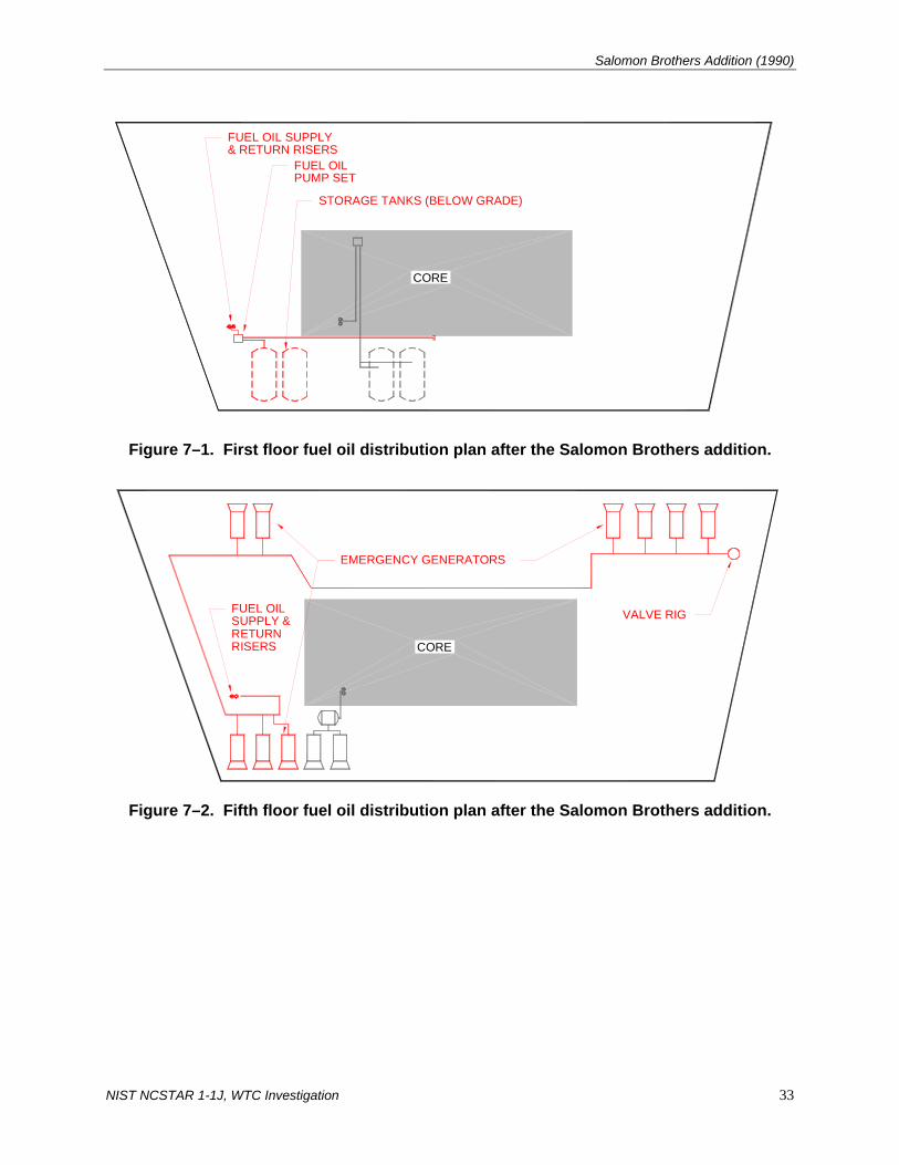
Salomon Brothers Addition (1990)
CORE
PUMP SETFUEL OIL
& RETURN RISERSFUEL OIL SUPPLY
STORAGE TANKS (BELOW GRADE)
Figure 7–1. First floor fuel oil distribution plan after the Salomon Brothers addition.
CORE
EMERGENCY GENERATORS
SUPPLY &FUEL OIL
RETURNRISERS
VALVE RIG
Figure 7–2. Fifth floor fuel oil distribution plan after the Salomon Brothers addition.
NIST NCSTAR 1-1J, WTC Investigation 33

Chapter 7
EXISTING BASE BULDINGDISTRIBUTION SYSTEM
1ST FLOOR
4TH FLOOR
3RD FLOOR
2ND FLOOR
5TH FLOOR
6TH FLOOR
7TH FLOOR
8TH FLOOR
9TH FLOOR
NEW EMERGENCYGENERATOR(TYP. OF 9)
NEW PUMP SET
NEW STORAGETANKS
Figure 7–3. Section plan of fuel oil distribution components after the Salomon Brothers
addition.
34 NIST NCSTAR 1-1J, WTC Investigation

Chapter 8 FINAL CONFIGURATION
World Trade Center (WTC) 7 contained two independent fuel oil distribution systems: the Salomon Brothers system and the Base Building system. The two 12,000 gal Base Building fuel oil tanks provided fuel to the two emergency generators on the 5th floor, which provided emergency power as required. The Base Building fuel oil distribution system also provided fuel to the Ambassador Construction generator on the 9th floor, the American Express generator on the 8th floor and the three generators for the Mayor’s Office of Emergency Management on the 7th floor. The two 6,000 gal Salomon Brothers fuel oil tanks provided fuel to the nine generators located on the 5th floor. The final configurations, as of September 11, 2001, of the two fuel oil distribution systems in WTC 7 are represented in Figs. 8–1 through 8–6. The component locations are approximated from the design drawings submitted to the Port Authority of New York and New Jersey for approval. Floor plans not shown between the 1st and 9th floors contain fuel oil risers only. For more specific locations and details, see the documented drawings listed in the Reference sections of each chapter of this report.
NIST NCSTAR 1-1J, WTC Investigation 35

Chapter 8
5TH FLOOR
4TH FLOOR
3RD FLOOR
2ND FLOOR
1ST FLOOR
DISTRIBUTION SYSTEMBASE BULDING
9TH FLOOR
8TH FLOOR
6TH FLOOR
7TH FLOOR
AMERICAN EXPRESSDISTRIBUTION SYSTEM
DISTRIBUTION SYSTEMAMBASSADOR CONSTRUCTION
SALOMON BROTHERSDISTRIBUTION SYSTEM
MAYOR'S OFFICEDISTRIBUTION SYSTEM
(QTY. OF 2)(QTY. OF 9)
(QTY. OF 3)
LEGEND
DAY TANK
STORAGE TANK
EMERGENCY GENERATOR
PUMP SET
Figure 8–1. Section plan showing the final locations of the fuel oil distribution
components.
36 NIST NCSTAR 1-1J, WTC Investigation

Final Configuration
CORE
Figure 8–2. Final location of 1st floor fuel oil distribution components.
CORE
Figure 8–3. Final location of 5th floor fuel oil distribution components.
NIST NCSTAR 1-1J, WTC Investigation 37

Chapter 8
CORE
Figure 8–4. Final location of 7th floor fuel oil distribution components.
CORE
Figure 8–5. Final location of 8th floor fuel oil distribution components.
38 NIST NCSTAR 1-1J, WTC Investigation
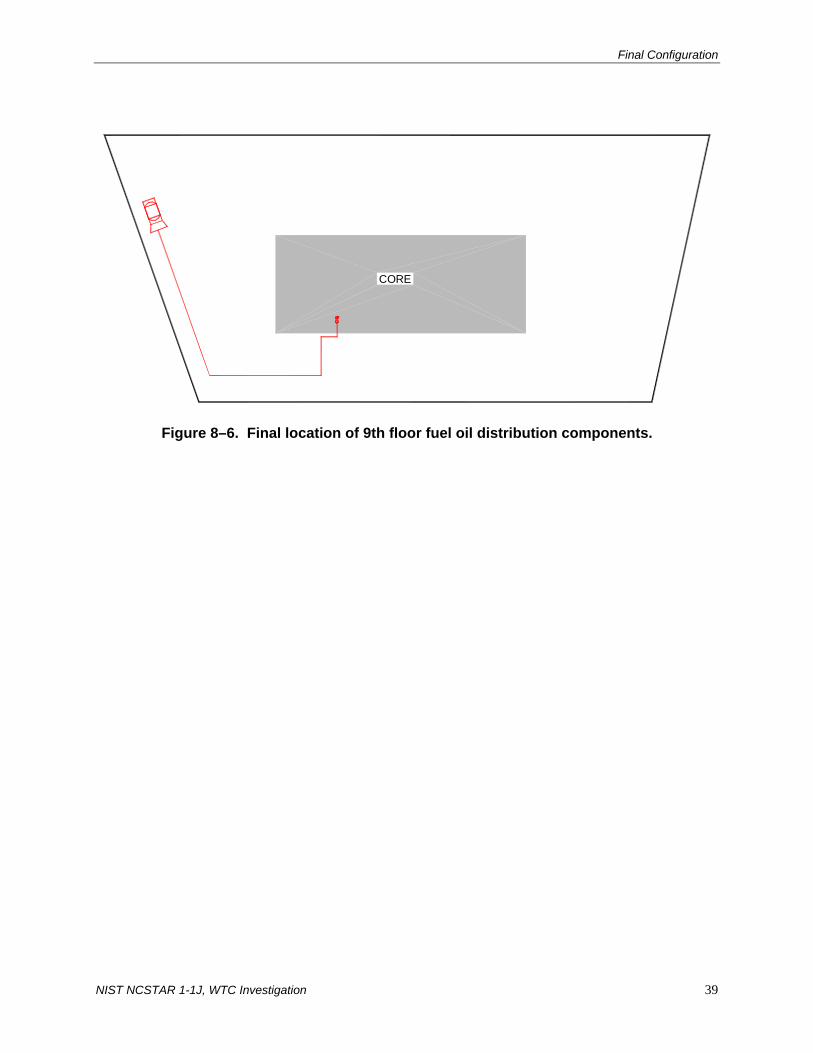
Final Configuration
CORE
Figure 8–6. Final location of 9th floor fuel oil distribution components.
NIST NCSTAR 1-1J, WTC Investigation 39

Chapter 8
40 NIST NCSTAR 1-1J, WTC Investigation
This page intentionally left blank.

Chapter 9 SYSTEM PERFORMANCE
9.1 BASE BUILDING FUEL OIL DISTRIBUTION SYSTEM
The Base Building fuel oil distribution system in World Trade Center (WTC) 7 was composed of four sub-systems, all having the same basic design: the Silverstein system, the Ambassador Construction system, the American Express system, and the Mayor’s Office of Emergency Management system. The fuel oil supply to each of the four sub-systems was supplied by the sub-grade storage tanks installed in the original Base Building design. However, the fuel oil pump set of each sub-system was independently regulated by a separate control panel (four total). Each fuel oil pump set was designed to start and stop the fuel oil supply as determined by the oil level in the respective day tank.
Details for all system components have not been identified from the available WTC documents and thus the functions of the components can only be assumed through brief design comments on the drawings, manufacturer’s product applications, and an understanding of the typical operation of the various components. Although each sub-system was not identical to the other, each system had the same basic design and many similar components; see Fig. 9–1 for typical locations. Although some components were not indicated in the design, it can be assumed that these components were installed due to the Building Code of the City of New York (BCNYC) requirements and/or basic understanding that the system would not perform without it. See Table 9–1 for a listing of each fuel oil device included in each sub-system design. The following sections discuss the probable functions and components installed in each sub-system.
9.1.1 Liquid Level Switches/Detectors and Collecting Pans/Rupture Basins
As previously stated, the duplex transfer pump set was programmed to operate based on the liquid level of the day tank. Each duplex pump set had a control panel located next to the pump set and/or next to the day tank that regulated the functions of the system. Each system was equipped with at least one liquid level switch in the day tank1. The liquid level switch(es) would turn the pump set on and off according to the level of fuel in the day tank. Upon detection of a low level in the day tank, the lead pump of the duplex pump set is started. Once the day tank is filled to the high level, the lead pump is stopped. In the event the lead pump is unable to provide sufficient flow to the day tank, the lag pump is started and operates until the high level is achieved, which stops the pump set.
The day tanks were installed in rupture basins to prevent unwanted fuel discharge from the day tank. The rupture basins installed had capacities of twice the capacity of the day tank. Most if not all of the rupture basins contained a leak detector to further assure that fuel would not continue to flow from a ruptured day tank. If a leak detector was present (most likely scenario since it is required by BCNYC), the system would send an alarm to the Building Management System and stop the pump upon detection of fuel in the
1 The Ambassador Construction project refers to a liquid control lever. Whether this was a single float switch or multiple
switches, the lever would have been capable of starting and stopping the pump set according to the fuel level.
NIST NCSTAR 1-1J, WTC Investigation 41

Chapter 9
rupture basin. If a leak detector was not present in the day tank rupture basin (not likely), then it would be possible to endlessly pump fuel onto the floor where the day tank is located until the selected storage tank was emptied. The only other scenario that could endlessly pump fuel onto the floor where the day tank is located would occur in the event of a break in the fuel oil supply (FOS) piping down stream of the day tank. This break could allow the day tank to reach a low level and start the pump set. Fuel would flow onto the floor where no fuel detection is present until the storage tank that was selected was emptied. It is unsure how likely this would be, understanding that lack of fuel to the generators would produce lack of power to the pump set.
Leak detectors at the base of the FOS riser and in the collecting pans helped prevent the unwanted flow of fuel. In the event of a break of the FOS discharge piping, the pump set would not start pumping fuel until the low level in the day tank was detected. Thus a break in the FOS discharge piping before a low level in the day tank was detected would not start the pump set. However, if a low level in the day tank was detected and the pump set started, and then a break occurred, there is a possibility that fuel would flow out the break in the pipe. But, it is also likely that the fuel would flow back down the outer pipe of the double wall piping construction to the base of the FOS riser and into the open sight fuel oil collecting pan where leak detectors are installed. The leak detector, upon detection of fuel, would stop the pump set and send an alarm to the Building Management System. Fuel would not likely flow endlessly out the break in the pipe.
There is another scenario that should be evaluated. The electrical wiring of the system should be analyzed. It may have been possible to have an electrical malfunction in the system and have the pump set start, with the possibility of pumping fuel endlessly out a pipe break. But, because the point to point wiring schematic of the control panel showing the connection of all the electrical devices has not been located, this scenario could not be evaluated.
9.1.2 Fusible Link Gate Valve
The fusible link gate valves included in the sub-system designs serve as an automatic shut off valve in the event of a fire. As the heat of the fire, within the room the valve is located, rises to the melting point of the fusible link, the link melts, the valve closes and the fuel flow in the FOS pipe is shut off. At this point, fuel flow is stopped until the gate valve is manually re-opened.
9.1.3 Anti-siphon Valve and Check Valve
Fuel systems that included an anti-siphon valve were protected from fuel siphoning from the storage tanks to the Fuel Oil Pump Room floor. Some designs included an anti-siphon valve installed at the highest point of the FOS pump suction piping (between the storage tanks and the pump set). The anti-siphon valve was installed to prevent the fuel in the storage tank from emptying onto the Fuel Oil Pump Room floor in the event of a pipe break. An anti-siphon valve opens as negative pressure is applied downstream of the valve. A pump creates enough negative pressure in the suction piping to open the valve, whereas, a pipe break in the suction piping does not create a sufficient amount of negative pressure to open the valve. But, siphoning of the fuel in the storage tanks was not likely to occur since the storage tanks were lower in elevation than the Fuel Oil Pump Room floor.
42 NIST NCSTAR 1-1J, WTC Investigation

System Performance
The only other siphoning situation that could occur in the Fuel Oil Pump Room would be siphoning from a day tank back to the Fuel Oil Pump Room. The anti-siphon valve would not be effective for this piping break, but siphoning may or may not occur for two other reasons. The FOS pipe leading to a day tank is connected at the top of the tank and most likely does not extend inside to the bottom of the tank. If the connection does not extend to the bottom of the tank, the air gap between the day tank fuel and the FOS pipe would eliminate the possibility of siphoning the fuel in the day tank to the Fuel Oil Pump Room floor. However, if the connection extended to the bottom of the tank, then siphoning could occur. Second, there are check valves in the pump set piping that prevent backflow of fuel. If the break occurred upstream of the check valve, no fuel would siphon back to the Fuel Oil Pump Room. Although, if the break occurred downstream of the check valve, siphoning may or may not occur, depending on the connection of the FOS piping to the day tank as stated above.
9.1.4 Foot Valve
The purpose of a foot valve was to keep the FOS pump suction piping primed with fuel and prevent the fuel from draining back to the storage tanks. A foot valve is similar to a check valve, but is supposedly more efficient than a check valve at keeping the line primed.
9.1.5 Pressure Relief Valve
The FOS pump discharge piping of every sub-system contained a relief valve that prevented excessive pressures from building up in the discharge piping. It is possible to build up excessive pressure in the pump discharge piping when a control valve or solenoid valve is closed and the pump set is on. The relief valve would prevent the pressure from rising above the predetermined relief valve setting by discharging fuel into the fuel oil return (FOR) pipe until the pressure decreased to below the setting. The designs had the pressure relief valve set to 100 psi to 125 psi.
9.1.6 Solenoid Valve
Most systems, if not all, had a solenoid valve located in the FOS pump discharge piping. The purpose of the solenoid valve in the FOS pump discharge piping was to prevent unwanted fuel discharge to the day tank. The solenoid valve was most likely programmed to close in an alarm situation. The Silverstein system required the solenoid valve to close on high level alarm in the day tank. This would prevent an overflow or continuous flow of fuel through the FOS pump discharge piping. It is unclear whether the solenoid valve was normally in the closed or open position.
9.1.7 Tank Selector Valve
A tank selector valve was installed in the Silverstein system. The switch was used to switch the fuel supply from one tank to the other. The valve was manually operated and only permitted one storage tank at a time to supply fuel to the pump set and day tanks. Thus, if the fuel in the primary tank was emptied, either by normal usage or unwanted discharge, the tank selector valve would have to be manually switched to the secondary storage tank to supply fuel to the pumps.
NIST NCSTAR 1-1J, WTC Investigation 43

Chapter 9
Figure 9–1. Typical layout of critical devices in Base Building sub-systems.
STORAGE TANKSTORAGE TANK
FOR
FOS
FOR
FOS
FOR
DUPLEX PUMP SET
LEGEND
FOS
FOS
FOR
S
FUEL OIL RETURN
FUEL OIL SUPPLY
TANK SELECTOR VALVE
SOLENOID VALVE
CHECK VALVE
PRESSURE RELIEF VALVE
ANTI-SYPHON VALVE
LINK LEVER GATE VALVE
FOR
FOS
TO GENERATOR
DAY TANK
44 NIST NCSTAR 1-1J, WTC Investigation

System Performance
Table 9–1. Critical fuel oil devices installed in Base Building sub-systems.
Fuel Oil Component Silverstein Ambassador Construction
American Express
Office of Emergency
Management Fusible link gate valve – Installed in fuel oil supply pump suction piping No Yes No No
Anti-syphon valve – Installed in fuel oil supply pump suction piping Yes Yes Yesa Yes
Foot valve – Installed in fuel oil supply pump suction piping Unknownb No No Yes
Check valve – Installed in fuel oil supply pump suction piping Yes Yes Yes Yes
Pressure relief valve – Installed in fuel oil supply pump discharge piping Yes Yes Yes Yes
Solenoid valve – Installed in fuel oil supply pump discharge piping Yes Yes Unknownc Yes
High level switch – Installed in day tank Yes Unknownd Yes Yes
Low level switch – Installed in day tank Yes Unknownd Assumed Yes
Rupture basin – Installed around day tank Yes Yes Yes Yes
Fusible link gate valve – In fuel oil supply between day tank and generator Yes No No No
Leak detector – Installed in day tank rupture basin Yes Assumed Yes Assumed
Leak detector – Installed at base of fuel oil supply/fuel oil return riser Unknowne Yes Yes Yes
Leak detector – Installed in pump room collecting drum Yes Yes Yes Yes
Tank selector valve – Installed in pump room collecting drum Yes Yesa Yesa Yesa
a. Included in the Silverstein system, which supplies fuel to the remaining three sub-systems. b. The Ambassador Construction modification refers to an existing 2 in. foot valve in the fuel oil supply pump suction piping. It
is most likely from the Silverstein system installation. c. Detailed piping schematic and specifications have not been identified. d. Specifications indicate that the pump set is to be energized from the float control lever. Operation of this lever is unclear. e. Riser details have not been located. Key: Yes, component shown on drawing or listed in design specification; No, component not shown on drawing or specifications; Assumed, based on requirements in the BCNYC, specifications, system capabilities or manufacturer’s recommendations, the component is likely to be installed, but not shown.
NIST NCSTAR 1-1J, WTC Investigation 45
Chapter 9
9.2 SALOMON BROTHERS FUEL OIL DISTRIBUTION SYSTEM
The Salomon Brothers fuel system had a similar but slightly different design in comparison to the Base Building fuel system. See Fig. 9–2 for the location of the critical devices. Two underground storage tanks supplied the duplex pump set with fuel. The fuel system was designed using a pressurized loop rather than day tanks. The FOS side of the loop ended with a valve rig that was designed to start and stop the fuel oil supply. The fuel supply was provided by a duplex pump set. Similar to the Base Building system, if the lead pump of the duplex pump set was unable to provide sufficient pressure in the FOS piping, the lag pump would start and operate until the high level was achieved.
The valve rig controlled the fuel supply pressure in the FOS piping. The liquid level switch in the valve rig controlled the fuel oil supply in the FOS piping. Upon detection of a low fuel level in the FOS pipe, the pump set would start. Once the high fuel level was achieved, the pump set would stop. The back pressure regulator (located just downstream of the liquid level switch) maintained the proper fuel pressure in the FOS piping. If excessive pressure built up in the FOS piping, the back pressure regulator would relieve the excessive pressure in the FOR piping which drained back to the storage tanks. In addition to the back pressure regulator in the valve rig, pressure relief valves on the FOS pump discharge piping were installed to assure the proper pressure in the FOS piping.
A tank selector valve was not included in the design. Drawings indicate that gate valves were included in the FOS pump suction pipes. It is unclear whether the FOS and FOR pipes to each tank were opened, allowing both tanks to supply fuel to the pumps or whether one set of valves were closed, allowing only one storage tank to supply fuel to the duplex pump set. Thus, it cannot be determined, based on the available documentation, whether one or both tanks would have supplied fuel to the pump set in the event of normal operations or unwanted fuel discharge.
A solenoid valve was installed in the FOS pipe to each generator. Documentation does not indicate the normal position (open or closed) of the solenoid valve. The solenoid valve was most likely wired to be closed when the pump was off and then open during the call for fuel to a particular generator. The solenoid valve could have been wired to close upon a detection of high fuel pressure in the FOS piping. The second scenario is not likely due to the presence of the back pressure regulator and pressure relief valve.
A check valve was installed in each FOR pipe from the generator to the FOR loop piping. The purpose of the check valve was to prevent any backflow of fuel from the FOR piping to the FOS piping.
A collecting tank and second valve rig were installed in the pump room. The purpose of an FOS pump suction valve rig is undetermined. The 55 gal collecting tank was connected to the FOR pipes and contained a float switch inside. It is unclear whether the float switch was to notify the presence of fuel or that the tank was nearly full. It is also unclear whether the switch stopped the pumps from supplying fuel to the FOS loop.
Based on the available documentation, the pressurized loop could have endlessly discharged fuel out of a broken FOS pipe. A break in the FOS pipe, between the pump set and FOS valve rig, could have activated the pump set. In the event of a FOS pipe break, the fuel could have emptied out of the valve rig, sending a low level signal to the pump controllers from the liquid level switch and starting the pump set. Fuel would have flowed out the break until the storage tank(s) were emptied. However, if the double
46 NIST NCSTAR 1-1J, WTC Investigation
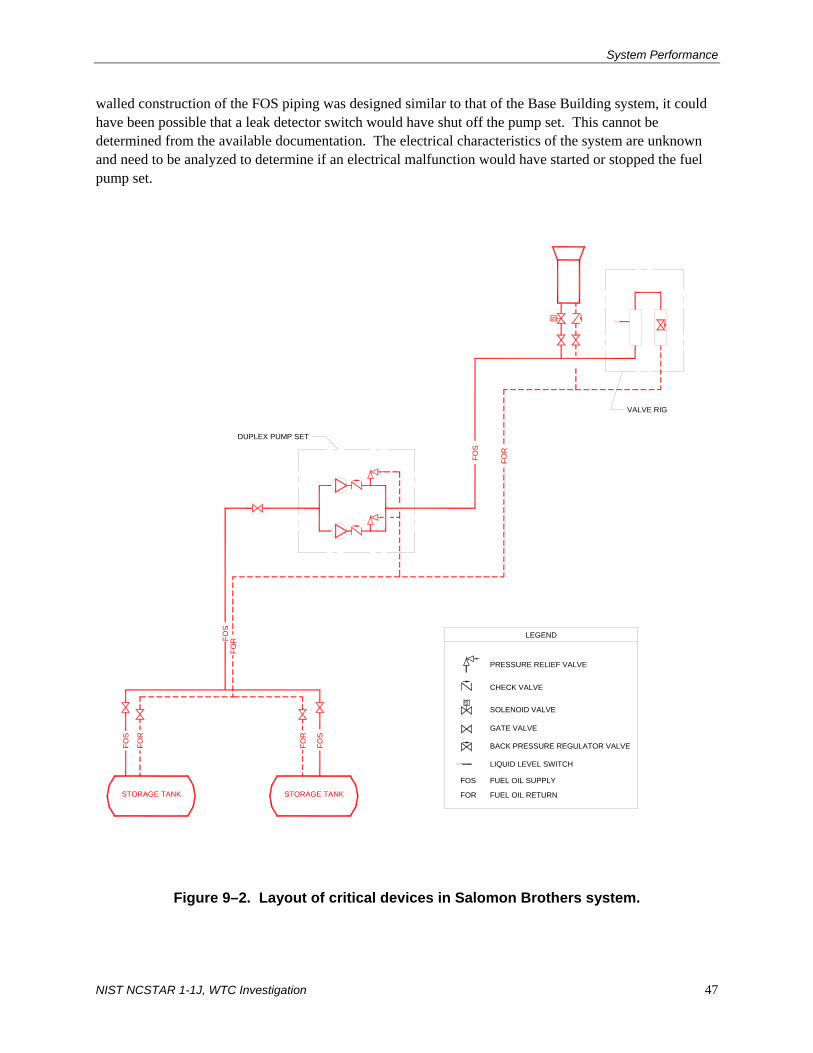
System Performance
walled construction of the FOS piping was designed similar to that of the Base Building system, it could have been possible that a leak detector switch would have shut off the pump set. This cannot be determined from the available documentation. The electrical characteristics of the system are unknown and need to be analyzed to determine if an electrical malfunction would have started or stopped the fuel pump set.
DUPLEX PUMP SET
Figure 9–2. Layout of critical devices in Salomon Brothers system.
FOR
STORAGE TANK
FOS
FOR
STORAGE TANK
FORFO
S
VALVE RIG
LIQUID LEVEL SWITCH
BACK PRESSURE REGULATOR VALVE
GATE VALVE
FUEL OIL RETURN
FUEL OIL SUPPLY
LEGEND
SOLENOID VALVE
CHECK VALVE
PRESSURE RELIEF VALVE
FOS
FOR
FOS
S
FOS
FOR
NIST NCSTAR 1-1J, WTC Investigation 47
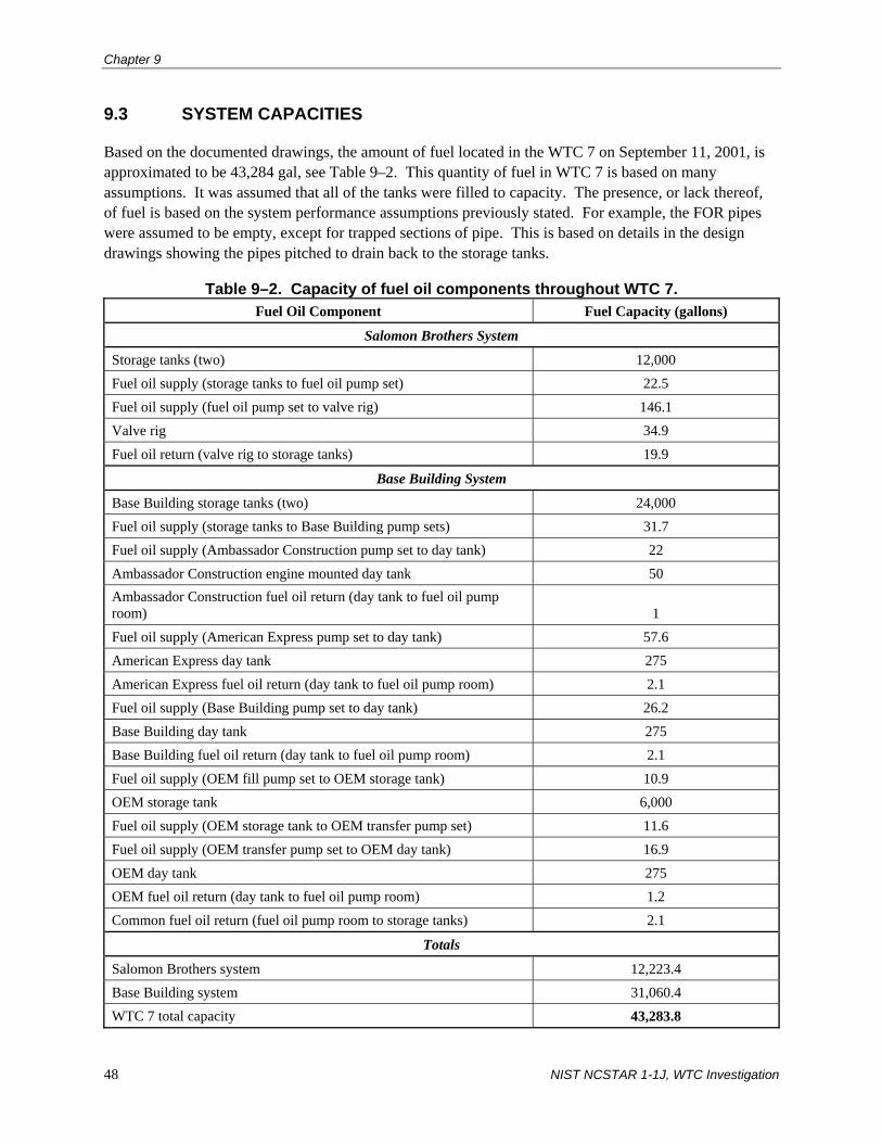
Chapter 9
48 NIST NCSTAR 1-1J, WTC Investigation
9.3 SYSTEM CAPACITIES
Based on the documented drawings, the amount of fuel located in the WTC 7 on September 11, 2001, is approximated to be 43,284 gal, see Table 9–2. This quantity of fuel in WTC 7 is based on many assumptions. It was assumed that all of the tanks were filled to capacity. The presence, or lack thereof, of fuel is based on the system performance assumptions previously stated. For example, the FOR pipes were assumed to be empty, except for trapped sections of pipe. This is based on details in the design drawings showing the pipes pitched to drain back to the storage tanks.
Table 9–2. Capacity of fuel oil components throughout WTC 7. Fuel Oil Component Fuel Capacity (gallons)
Salomon Brothers System
Storage tanks (two) 12,000 Fuel oil supply (storage tanks to fuel oil pump set) 22.5 Fuel oil supply (fuel oil pump set to valve rig) 146.1 Valve rig 34.9 Fuel oil return (valve rig to storage tanks) 19.9
Base Building System
Base Building storage tanks (two) 24,000 Fuel oil supply (storage tanks to Base Building pump sets) 31.7 Fuel oil supply (Ambassador Construction pump set to day tank) 22 Ambassador Construction engine mounted day tank 50 Ambassador Construction fuel oil return (day tank to fuel oil pump room) 1 Fuel oil supply (American Express pump set to day tank) 57.6 American Express day tank 275 American Express fuel oil return (day tank to fuel oil pump room) 2.1 Fuel oil supply (Base Building pump set to day tank) 26.2 Base Building day tank 275 Base Building fuel oil return (day tank to fuel oil pump room) 2.1 Fuel oil supply (OEM fill pump set to OEM storage tank) 10.9 OEM storage tank 6,000 Fuel oil supply (OEM storage tank to OEM transfer pump set) 11.6 Fuel oil supply (OEM transfer pump set to OEM day tank) 16.9 OEM day tank 275 OEM fuel oil return (day tank to fuel oil pump room) 1.2 Common fuel oil return (fuel oil pump room to storage tanks) 2.1
Totals
Salomon Brothers system 12,223.4 Base Building system 31,060.4 WTC 7 total capacity 43,283.8

Chapter 10 MAINTENANCE HISTORY
Documentation for the maintenance history of the two distribution systems could not be located. A Silverstein document indicates the maintenance schedule of three generators and four fuel oil pumps. There are also notes on upgrades for the same items. The only other maintenance history document found is in an inspection report dated April 1997, which indicates that the fuel lines in the 5th floor Generator Room were missing pipe supports. The maintenance schedule for the Silverstein items as indicated in the Silverstein document are as follows.
Table 10–1. Maintenance schedule of fuel oil pumps and generators.
Description Location Maintenance Schedule Upgrades Generator 1 5th floor Generator Room Weekly, monthly,
semiannual, annual New load bank and voltage regulator
Generator 2 5th floor Generator Room Weekly, monthly, semiannual, annual
New load bank and voltage regulator
Generator 9-1 9th floor USSS Weekly, monthly, semiannual, annual
New generator
Fuel Oil Pump 1 Fuel Oil Pump Room Weekly, quarterly, semiannual
Fuel Oil Pump 2 Fuel Oil Pump Room Weekly, quarterly, semiannual
Tenant Fuel Oil Pump 1 Fuel Oil Pump Room Weekly, quarterly, semiannual
New pump and controls
Tenant Fuel Oil Pump 2 Fuel Oil Pump Room Weekly, quarterly, semiannual
New pump and controls
Source: Silverstein.
NIST NCSTAR 1-1J, WTC Investigation 49

Chapter 10
50 NIST NCSTAR 1-1J, WTC Investigation
This page intentionally left blank.