Write the serial number in the space User’s Manual...
28
Serial Number Decal Model No. 831.24723.0 Serial No. CAUTION Read all precautions and instruc- tions in this manual before using this equipment. Save this manual for future reference. TREADMILL EXERCISER User’s Manual • Assembly • Operation • Maintenance • Part List and Drawing Sears, Roebuck and Co., Hoffman Estates, IL 60179 Write the serial number in the space above for future reference.
Transcript of Write the serial number in the space User’s Manual...

SerialNumber
Decal
Model No. 831.24723.0 Serial No.
CAUTIONRead all precautions and instruc-tions in this manual before usingthis equipment. Save this manualfor future reference.
TREADMILL EXERCISERUser’s Manual
• Assembly
• Operation
• Maintenance
• Part List and Drawing
Sears, Roebuck and Co., Hoffman Estates, IL 60179
Write the serial number in the spaceabove for future reference.

TABLE OF CONTENTS
WARNING DECAL PLACEMENT . . . . . . . . . . . . . . . . . . . . . . . . . . . . . . . . . . . . . . . . . . . . . . . . . . . . . . . . . . . . . .2IMPORTANT PRECAUTIONS . . . . . . . . . . . . . . . . . . . . . . . . . . . . . . . . . . . . . . . . . . . . . . . . . . . . . . . . . . . . . . . .3BEFORE YOU BEGIN . . . . . . . . . . . . . . . . . . . . . . . . . . . . . . . . . . . . . . . . . . . . . . . . . . . . . . . . . . . . . . . . . . . . . .5ASSEMBLY . . . . . . . . . . . . . . . . . . . . . . . . . . . . . . . . . . . . . . . . . . . . . . . . . . . . . . . . . . . . . . . . . . . . . . . . . . . . . . .6OPERATION AND ADJUSTMENT . . . . . . . . . . . . . . . . . . . . . . . . . . . . . . . . . . . . . . . . . . . . . . . . . . . . . . . . . . . .11HOW TO FOLD AND MOVE THE TREADMILL . . . . . . . . . . . . . . . . . . . . . . . . . . . . . . . . . . . . . . . . . . . . . . . . . .17TROUBLESHOOTING . . . . . . . . . . . . . . . . . . . . . . . . . . . . . . . . . . . . . . . . . . . . . . . . . . . . . . . . . . . . . . . . . . . . .18EXERCISE GUIDELINES . . . . . . . . . . . . . . . . . . . . . . . . . . . . . . . . . . . . . . . . . . . . . . . . . . . . . . . . . . . . . . . . . . .21PART LIST . . . . . . . . . . . . . . . . . . . . . . . . . . . . . . . . . . . . . . . . . . . . . . . . . . . . . . . . . . . . . . . . . . . . . . . . . . . . . .22EXPLODED DRAWING . . . . . . . . . . . . . . . . . . . . . . . . . . . . . . . . . . . . . . . . . . . . . . . . . . . . . . . . . . . . . . . . . . . .2490 DAY FULL WARRANTY . . . . . . . . . . . . . . . . . . . . . . . . . . . . . . . . . . . . . . . . . . . . . . . . . . . . . . . . . .Back Cover
2
The decals shown here have been ap-plied in the locations shown. If a decalis missing, or if it is not legible, call1-888-533-1333 and order a free re-placement decal. Apply the decal inthe location shown. Note: The decalsmay not be shown at actual size.
WARNING DECAL PLACEMENT

3
1. Before beginning any exercise program, con-sult your physician. This is especially impor-tant for persons over the age of 35 or personswith pre-existing health problems.
2. It is the responsibility of the owner to ensurethat all users of this treadmill are adequatelyinformed of all warnings and precautions.
3. Use the treadmill only as described.
4. Place the treadmill on a level surface, with atleast 8 ft. (2.4 m) of clearance behind it and 2ft. (0.6 m) on each side. Do not place thetreadmill on any surface that blocks air open-ings. To protect the floor or carpet from dam-age, place a mat under the treadmill.
5. Keep the treadmill indoors, away from mois-ture and dust. Do not put the treadmill in agarage or covered patio, or near water.
6. Do not operate the treadmill where aerosolproducts are used or where oxygen is beingadministered.
7. Keep children under the age of 12 and petsaway from the treadmill at all times.
8. The treadmill should be used only by personsweighing 250 lbs. (113 kg) or less.
9. Never allow more than one person on thetreadmill at a time.
10. Wear appropriate exercise clothes whenusing the treadmill. Do not wear loose clothesthat could become caught in the treadmill.Athletic support clothes are recommendedfor both men and women. Always wear ath-letic shoes. Never use the treadmill with barefeet, wearing only stockings, or in sandals.
11. When connecting the power cord (see page11), plug the power cord into a surge sup-pressor (not included) and plug the surgesuppressor into a grounded circuit capable ofcarrying 15 or more amps. No other appliance
should be on the same circuit. Do not use anextension cord.
12. Use only a single-outlet surge suppressor thatmeets all of the specifications described onpage 11. To purchase a surge suppressor, seeyour local Sears store or call the telephonenumber on the back cover of this manual andorder part number 146148, or see your localelectronics store.
13. Failure to use a properly functioning surgesuppressor could result in damage to the con-trol system of the treadmill. If the control sys-tem is damaged, the walking belt may changespeed, accelerate, or stop unexpectedly,which may result in a fall and serious injury.
14. Keep the power cord and the surge suppres-sor away from heated surfaces.
15. Never move the walking belt while the poweris turned off. Do not operate the treadmill ifthe power cord or plug is damaged, or if thetreadmill is not working properly. (See TROU-BLESHOOTING on page 18 if the treadmill isnot working properly.)
16. Read, understand, and test the emergencystop procedure before using the treadmill (seeHOW TO TURN ON THE POWER on page 13).
17. Never start the treadmill while you are stand-ing on the walking belt. Always hold thehandrails or crosswalk arms while using thetreadmill.
18. The treadmill is capable of high speeds.Adjust the speed in small increments to avoidsudden jumps in speed.
19. The pulse sensor is not a medical device.Various factors, including the user's move-ment, may affect the accuracy of heart ratereadings. The pulse sensor is intended onlyas an exercise aid in determining heart ratetrends in general.
WARNING: To reduce the risk of serious injury, read all important precautions and in-structions in this manual and all warnings on your treadmill before using your treadmill. Sears as-sumes no responsibility for personal injury or property damage sustained by or through the use ofthis product.
IMPORTANT PRECAUTIONS
4
20. Never leave the treadmill unattended while itis running. Always remove the key, unplugthe power cord, and switch the reset/off cir-cuit breaker to the off position when thetreadmill is not in use. (See the drawing onpage 5 for the location of the circuit breaker.)
21. Do not attempt to raise, lower, or move thetreadmill until it is properly assembled. (SeeASSEMBLY on page 6, and HOW TO FOLDAND MOVE THE TREADMILL on page 17.)You must be able to safely lift 45 lbs. (20 kg)to raise, lower, or move the treadmill.
22. When folding or moving the treadmill, makesure that the storage latch is fully closed.
23. Never insert any object into any opening onthe treadmill.
24. Inspect and properly tighten all parts of thetreadmill regularly.
25. DANGER: Always unplug the powercord immediately after use, before cleaning thetreadmill, and before performing the mainte-nance and adjustment procedures described inthis manual. Never remove the motor hood un-less instructed to do so by an authorized ser-vice representative. Servicing other than theprocedures in this manual should be performedby an authorized service representative only.
26. This treadmill is intended for in-home useonly. Do not use this treadmill in a commer-cial, rental, or institutional setting.
SAVE THESE INSTRUCTIONS

5
Thank you for selecting the revolutionary PROFORM®
CROSSWALK 415 treadmill. The CROSSWALK 415treadmill offers an impressive array of features de-signed to make your workouts at home more enjoyableand effective. And when you’re not exercising, theunique CROSSWALK 415 treadmill can be folded up,requiring less than half the floor space of other tread-mills.
For your benefit, read this manual carefully before
using the treadmill. If you have questions after read-ing this manual, call 1-800-4-MY-HOME® (1-800-469-4663).To help us assist you, please note the productmodel number and serial number before contacting us.The model number and the location of the serial num-ber decal are shown on the front cover of this manual.
Before reading further, please review the drawingbelow and familiarize yourself with the labeled parts.
BEFORE YOU BEGIN
Handrail
Upright
Crosswalk Arm
Key/Clip
Reset/Off Circuit Breaker
Walking Belt
Cushioned Walking Platformfor maximum exercise comfort
Foot Rail
Power Cord
RIGHT SIDE
Rear Roller Adjustment Bolts
Console
Book Holder
Storage Latch
Accessory Tray
Pulse Sensor
BACK

ASSEMBLYMake sure that the power cord is unplugged. Assembly requires two persons. Set the treadmill in a clearedarea and remove all packing materials. Do not dispose of the packing materials until assembly is completed. Note:The underside of the treadmill walking belt is coated with high-performance lubricant. During shipping, a smallamount of lubricant may be transferred to the top of the walking belt or the shipping carton. This is a normal con-dition and does not affect treadmill performance. If there is lubricant on top of the walking belt, simply wipe off thelubricant with a soft cloth and a mild, non-abrasive cleaner.
Assembly requires the included hex keys , your own Phillips screwdriver , and an adjustable wrench .
Use the drawings below to identify the assembly hardware. The number in parentheses below each drawing isthe key number of the part, from the PART LIST near the end of this manual. The number after the parenthesesis the quantity needed for assembly. Note: If a part is not in the parts bag, check to see if it is preattached to oneof the parts to be assembled. Extra hardware may be included. If a part is missing, call 1-888-533-1333. Toavoid damaging plastic parts, do not use power tools for assembly.
1. Make sure that the power cord is unplugged.With the help of a second person, carefully tipthe treadmill onto its left side. Partially fold theFrame (48) so that the treadmill is more stable;do not fully fold the Frame yet.
Remove and discard the two indicated bolts (A)and the shipping bracket (B).
Cut the tie securing the Upright Wire (77) to theBase (85). Locate the tie in the indicated hole inthe Base, and use the tie to pull the Upright Wireout of the hole.
Attach a Base Pad (81) to the Base (85) in thelocation shown with a Base Pad Spacer (104)and an M4 x 25mm Screw (2). Then, attach an-other Base Pad with only a Screw.
Base Pad Spacer(104)–2
M8 StarWasher (10)–4
M10 StarWasher (8)–8
M4 x 19mmScrew (1)–6 M8 x 25mm Bolt (6)–4
M4 x 13mmScrew (3)–1
1/4" Washer(9)–4
M4 x 25mmScrew (2)–4
1/4" x 3 1/2" Bolt (4)–4
M10 x 96mm Bolt (5)–4Bolt Spacer (79)–4
852
48
81
A
1
812
77
BTie
Hole
104
6

7
2. Remove the M10 Nut (33), the M10 x 50mm Bolt(27), and the shipping bracket (C) from the Base(85). Attach a Wheel (86) with the Bolt and theNut that you just removed. Do not overtightenthe Nut; the Wheel must turn freely. Discardthe shipping bracket.
Cut the tie off the Upright Wire (77).
85
77Tie
27
C
33
2
86
3. Identify the Right Upright (78) and the RightUpright Spacer (80), which are marked withstickers. Insert the Upright Wire (77) through theRight Upright Spacer as shown.
See the inset drawing. Tie the wire tie in theRight Upright (78) securely around the end ofthe Upright Wire (77). With the help of a secondperson, hold the Right Upright near the Base(85). Then, pull the other end of the wire tie untilthe Upright Wire is routed completely throughthe Right Upright.
85
77
78
80
77
3
WireTie
Rounded Corner
78
77
4. Hold a Bolt Spacer (79) inside the lower end ofthe Right Upright (78). Insert a M10 x 96mmBolt (5) with a M10 Star Washer (8) into theRight Upright and the Bolt Spacer. Repeat thisstep with a second Bolt Spacer, Bolt, and StarWasher.
Hold the Right Upright Spacer (80) and theRight Upright (78) against the Base (85). Becareful not to pinch the Upright Wire (77).Finger tighten the M10 x 96mm Bolts (5); do notfully tighten the Bolts yet.
Press a Base Endcap (82) into the Base (85).
80
78
778
82
79
79
54
85
Tie

8
7. Set the Console (87) face down on a soft sur-face to avoid scratching the Console. Identifythe Right Handrail (90), which has a large holein the location shown. Hold the Right Handrailnear the Console. Attach the console groundwire to the Right Handrail with an M4 x 13mmScrew (3).
Next, insert the console wire into the large holein the Right Handrail (90) and out of the top asshown. attach the Right Handrail with three M4 x19mm Screws (1). Make sure that no wires arepinched. Start all three Screws before tight-ening any of them; do not overtighten theScrews.
Attach the Left Handrail (not shown) to theConsole (87) in the same way. Note: There areno wires on the left side of the Console.
90
7
87
1
1
Large Hole
ConsoleWire
3
ConsoleGround Wire
6. With the help of a second person, hold a BoltSpacer (79) inside the lower end of the LeftUpright (73). Insert a M10 x 96mm Bolt (5) witha M10 Star Washer (8) into the Left Upright andthe Bolt Spacer. Repeat this step with a secondBolt Spacer, Bolt, and Star Washer.
Orient the Left Upright (73) and the Left UprightSpacer (83) as shown. Hold the Left UprightSpacer and the Left Upright against the Base(85). Finger tighten the M10 x 96mm Bolts (5);do not fully tighten the Bolts yet.
Press a Base Endcap (82) into the Base (85).
With the help of a second person, tip the tread-mill so that the Base (85) is flat on the floor.
83
735
8579
79
82
8
6
RoundedCorner
5. With the help of a second person, carefully tipthe treadmill onto its right side. Partially fold theFrame (48) so the treadmill is more stable; donot fully fold the Frame yet.
Remove and discard the two indicated bolts (A)and the shipping bracket (B).
Attach a Base Pad (81) to the Base (85) in thelocation shown with a Base Pad Spacer (104)and an M4 x 25mm Screw (2). Then, attach an-other Base Pad with only a Screw.
Remove the M10 Nut (33), the M10 x 50mmBolt (27), and the shipping bracket (C) from theBase (85). Attach a Wheel (86) with the Bolt andthe Nut that you just removed. Do not over-tighten the Nut; the Wheel must turn freely.Discard the shipping bracket.
5
85
86
48
27
33C
81
2
81
104
2
BA

9
8. Have a second person hold the console assem-bly near the Right Upright (78). Remove the wiretie from the Upright Wire (77) and console wire.
Connect the Upright Wire (77) to the consolewire. Make sure to connect the connectorsproperly (see the inset drawing). The connec-tors should slide together easily and snapinto place. If they do not, turn one connector andtry again. IF THE CONNECTORS ARE NOTCONNECTED PROPERLY, THE CONSOLEMAY BE DAMAGED WHEN THE POWER ISTURNED ON. Then, insert the connectors intothe Right Upright (78).
Set the console assembly on the Right Upright(78) and the Left Upright (not shown). Make surethat no wires are pinched.
78
Console Assembly
Console Wire77
8
9. Finger tighten two M8 x 25mm Bolts (6) with twoM8 Star Washers (10) into the Left Upright (73)and the Left Handrail (89).
Next, finger tighten two M8 x 25mm Bolts (6)with two M8 Star Washers (10) into the RightUpright (78) and the Right Handrail (90). Then,tighten all four Handrail Bolts.
See steps 4 and 6. Tighten the four M10 x96mm Bolts (5).
6
6
6
10 73
10
6
10
89
90
78
9
77

10
12. Make sure that all parts are properly tightened before you use the treadmill. If there are sheets of clearplastic on the treadmill decals, remove the plastic. To protect the floor or carpet, place a mat under the tread-mill. Keep the included hex keys in a secure place; the large hex key is used to adjust the walking belt (seepage 19).
10. Press the Latch Insert (70) into the Left Upright(73).
Remove the knob from the pin. Make sure thatthe collar and the spring are on the pin. Insertthe pin into the Latch Insert (70), and tighten theknob back onto the pin.
Knob
70
10
73
11. Attach the Left Crosswalk Arm (71) to the LeftUpright (73) with two M10 Star Washers (8), two1/4" Washers (9), and two 1/4" x 3 1/2" Bolts (4).Be sure that the Left Crosswalk Arm is on theside of the Console (87) shown.
Attach the Right Crosswalk Arm (not shown) inthe same way.
4
9
11
7371
8
Spring
Pin
Collar
87

OPERATION AND ADJUSTMENT
THE PRE-LUBRICATED WALKING BELT
Your treadmill features a walking belt coated with high-performance lubricant. IMPORTANT: Never apply sil-icone spray or other substances to the walkingbelt or the walking platform. Such substances willdeteriorate the walking belt and cause excessivewear.
HOW TO PLUG IN THE POWER CORD
Your treadmill, like any other type of sophisticatedelectronic equipment, can be seriously damaged bysudden voltage changes in your home’s power.Voltage surges, spikes, and noise interference can result from weather conditions or from other appliancesbeing turned on or off. To decrease the possibility ofyour treadmill being damaged, always use a surgesuppressor with your treadmill (see drawing 1 atthe right). To purchase a surge suppressor, seeyour local Sears store or call the telephone numberon the back cover of this manual and order partnumber 146148, or see your local electronics store.
Use only a single-outlet surge suppressor that isUL 1449 listed as a transient voltage surge sup-pressor (TVSS). The surge suppressor must have aUL suppressed voltage rating of 400 volts or lessand a minimum surge dissipation of 450 joules.The surge suppressor must be electrically rated for120 volts AC and 15 amps. There must be a moni-toring light on the surge suppressor to indicatewhether it is functioning properly. Failure to use aproperly functioning surge suppressor could resultin damage to the control system of the treadmill. Ifthe control system is damaged, the walking beltmay change speed, accelerate, or stop unexpect-edly, which may result in a fall and serious injury.
This product must be grounded. If it should malfunc-tion or break down, grounding provides a path of leastresistance for electric current to reduce the risk of elec-tric shock. This product is equipped with a cord having
an equipment-grounding conductor and a groundingplug. Plug the power cord into a surge suppressor,and plug the surge suppressor into an appropriateoutlet that is properly installed and grounded inaccordance with all local codes and ordinances.Important: The treadmill is not compatible withGFCI-equipped outlets.
This product is for use on a nominal 120-volt circuit,and has a grounding plug that looks like the plug illus-trated in drawing 1 below. A temporary adapter thatlooks like the adapter illustrated in drawing 2 may beused to connect the surge suppressor to a 2-pole receptacle as shown in drawing 2 if a properly grounded outlet is not available.
The temporary adapter should be used only until aproperly grounded outlet (drawing 1) can be installedby a qualified electrician.
The green-colored rigid ear, lug, or the like extendingfrom the adapter must be connected to a permanentground such as a properly grounded outlet box cover.Whenever the adapter is used it must be held in placeby a metal screw. Some 2-pole receptacle outlet boxcovers are not grounded. Contact a qualified elec-trician to determine if the outlet box cover isgrounded before using an adapter.
DANGER: Improper connectionof the equipment-grounding conductor canresult in an increased risk of electric shock.Check with a qualified electrician or service-man if you are in doubt as to whether theproduct is properly grounded. Do not modifythe plug provided with the product—if it willnot fit the outlet, have a proper outlet installed by a qualified electrician.
1
2
Grounded Outlet Box
Grounded Outlet Box
Grounding Plug
Surge Suppressor
Surge Suppressor
Grounding Pin
Adapter
Lug
Metal Screw
Grounded Outlet
Grounding Pin
11

12
FEATURES OF THE CONSOLE
The treadmill console offers an impressive array of features designed to make your workouts more effec-tive and enjoyable.
When you use the manual mode, you can change thespeed and incline of the treadmill with the touch of abutton. As you exercise, the console will display instantexercise feedback. You can even measure your heartrate using the handgrip pulse sensor.
In addition, the console offers six iFit custom-fit presetworkouts, three of these use the crosswalk arms. Eachworkout automatically controls the speed and incline ofthe treadmill as it guides you through an effective exer-cise session.
To use the manual mode of the console, follow thesteps beginning on page 13. To use a preset work-out, see page 15.
Note: If there is a sheet of clear plastic on the console,remove the plastic. To prevent damage to the walkingplatform, wear clean athletic shoes while using thetreadmill. The first time you use the treadmill, observethe alignment of the walking belt, and center the walk-ing belt if necessary (see page 19).
Note: The console can display speed and distance ineither miles or kilometers. To find out which unit ofmeasurement is selected or to change the unit of mea-surement, see THE INFORMATION MODE on page16. Note: For simplicity, all instructions in this sectionrefer to miles.
Key
Clip
CONSOLE DIAGRAM
Note: If there are sheets of clear plas-tic on the console, remove the plastic.

13
HOW TO TURN ON THE POWER
IMPORTANT: If the treadmill has been exposed tocold temperatures, allow it to warm to room tem-perature before turning on the power. If you do notdo this, the console displays or other electricalcomponents may become damaged.
Plug in the power cord (seepage 11). Next, locate thereset/off circuit breaker onthe treadmill frame near thepower cord. Switch the circuitbreaker to the reset position.
IMPORTANT: The console features a display demomode, designed to be used if the treadmill is dis-played in a store. If the displays light as soon asyou plug in the power cord and switch the circuitbreaker to the reset position, the demo mode isturned on. To turn off the demo mode, hold downthe Stop button for a few seconds. If the displaysremain lit, see THE INFORMATION MODE on page16 to turn off the demo mode.
Next, stand on the foot rails of the treadmill. Find theclip attached to the key (see the drawing on page 12)and slide the clip onto the waistband of your clothes.Then, insert the key into the console. After a moment,the displays will light. IMPORTANT: In an emergencysituation, the key can be pulled from the console,causing the walking belt to slow to a stop. Test theclip by carefully taking a few steps backward; if thekey is not pulled from the console, adjust the posi-tion of the clip.
HOW TO USE THE MANUAL MODE
1. Insert the key into the console.
See HOW TO TURN ON THE POWER to the left.
2. Select the manual mode.
When the key is inserted, the manual mode will beselected. If a preset workout has been selected, re-move the key and then reinsert it.
3. Start the walking belt.
To start the walking belt, press the Go button, theSpeed increase button, or one of the speed buttonsnumbered 2 through 10.
If you press the Go button or the Speed increasebutton, the walking belt will begin to move at 1 mph.As you exercise, change the speed of the walkingbelt as desired by pressing the Speed increase anddecrease buttons. Each time you press a button,the speed setting will change by 0.1 mph; if youhold down a button, the speed setting will changein increments of 0.5 mph. Note: After you press abutton, it may take a moment for the walking belt toreach the selected speed setting.
If you press one of the numbered speed buttons, thewalking belt will gradually increase in speed until itreaches the selected speed setting.
To stop the walking belt, press the Stop button.The time will begin to flash in the display. To restartthe walking belt, press the Go button or the Speedincrease button.
4. Change the incline of the treadmill as desired.
To change the incline ofthe treadmill, press theIncline increase or de-crease buttons. Each timeyou press the Incline in-crease or decrease button, the incline will changeby 0.5%. Note: After you press a button, it may takea moment for the treadmill to reach the selected in-cline setting.
ResetPosition

14
5. Follow your progress with the displays.
The lower left display—As you exercise, thelower left display canshow the elapsed timeand the distance that youhave walked or run. Thelower left display will also show the incline of thetreadmill each time the incline level changes.
The lower right dis-play—The lower rightdisplay can show the ap-proximate number ofcalories that you haveburned and the speed ofthe walking belt. The display also shows your heartrate when you use the handgrip pulse sensor (seestep 6).
The upper dis-play—The upperdisplay can showthe elapsed time,the distance thatyou have walkedor run, the approximate number of calories that youhave burned, or the speed of the walking belt. Pressthe Display button repeatedly until the upper displayshows the information that you are most interestedin viewing. Note: While information is shown in theupper display, the same information will not beshown in the lower displays.
To reset the displays, press the Stop button, re-move the key, and then reinsert the key.
6. Measure your heart rate if desired.
Before using thehandgrip pulsesensor, removethe sheets ofclear plastic fromthe metal con-tacts on the pulsebar. In addition,make sure thatyour hands are clean.
To measure your heart rate, stand on the footrails and hold the pulse bar with your palms on themetal contacts. Avoid moving your hands. Whenyour pulse is detected, a heart symbol in the lowerright display will flash each time your heart beats,one or two dashes will appear, and then your heartrate will be shown. For the most accurate heartrate reading, continue to hold the contacts forabout 15 seconds.
7. When you are finished exercising, remove thekey from the console.
Step onto the foot rails, press the Stop button, andadjust the incline of the treadmill to the lowestsetting. The incline must be at the lowest settingor you may damage the treadmill when you foldit to the storage position. Next, remove the keyfrom the console and put it in a secure place.
When you are finished using the treadmill, switchthe reset/off circuit breaker to the “off” position andunplug the power cord. IMPORTANT: If you donot do this, the treadmill’s electrical compo-nents may wear prematurely.
Contacts

15
HOW TO USE A PRESET WORKOUT
1. Insert the key into the console.
See HOW TO TURN ON THE POWER on page 13.
2. Select a preset workout.
To select a preset work-out, press the SelectWorkout button repeat-edly until the number ofthe desired workout ap-pears in the upper dis-play. Note: The name, number, and profile of eachworkout is listed on the console.
When you select a preset workout, the incline levelof the workout will flash in the lower left display, thespeed setting will flash in the upper display, andthen the workout length will appear in the lower leftdisplay.
3. Select length of workout if desired.
If you have selected workout 1, 2, or 3, you can setthe length of the workout to a time between 15 and45 minutes, in increments of 5 minutes. To set thelength of the workout press the Set Time increaseor decrease button until the desired time is se-lected. The new workout settings will appear in thedisplays.
4. Press the Go button or the Speed increase but-ton to start the workout.
A moment after you press the button, the treadmillwill automatically adjust to the first speed and in-cline settings of the workout. Hold the handrails andbegin walking.
Each workout is divided into 30 one-minute seg-ments, unless you have changed the length of theworkout (see step 3). One speed setting and oneincline setting are programmed for each segment.Note: The same speed setting and/or incline settingmay be programmed for two or more consecutivesegments.
Tones will sound at the end of each segment.Three seconds before the speed and/or incline ofthe treadmill is about to change, the Speed displayand/or Incline display will flash and a series of toneswill sound to alert you. The treadmill will then auto-matically adjust to the speed and/or incline settingsfor the next segment.
If you have selected workout 4, 5 or 6, you will beprompted to use the crosswalk arms. When thecrosswalk indicator lights up, move the crosswalkarms forward and backward as you walk on thetreadmill. This action exercises your arms, shoul-ders, and back for a total body workout,
The workout will continue in this way until the lastsegment ends. The walking belt will then slow to astop.
If the speed or incline setting is too high or too lowat any time during the workout, you can manuallyoverride the setting by pressing the speed or inclinebuttons. Note: When the next segment of theworkout begins, the treadmill will automaticallyadjust to the speed and incline settings for thenext segment.
To stop the workout at any time, press the Stopbutton. To restart the workout, press the Go button.The walking belt will begin to move at 1 mph. Whenthe next segment of the workout begins, the tread-mill will automatically adjust to the speed and inclinesettings for the next segment.
5. Follow your progress with the displays.
See step 5 on page 14.
6. Measure your heart rate if desired.
See step 6 on page 14.
7. When you are finished exercising, remove thekey from the console.
See step 7 on page 14.

16
THE INFORMATION MODE
The console features an information mode that keepstrack of the total distance that the walking belt hasmoved and the total number of hours that the treadmillhas been used. The information mode also allows youto select a measurement system of miles or kilometersand turn on and off the display demo mode.
To select the information mode, hold down the Stopbutton while inserting the key into the console and thenrelease the Stop button. When the information mode isselected, the following information will be shown:
An “E” for English miles oran “M” for metric kilometerswill appear in the lower rightdisplay. Press the Speed in-crease button to change theunit of measurement if de-sired.
The lower left display willshow the total number ofmiles (or kilometers) that thewalking belt has moved.
The upper display will showthe total number of hours thetreadmill has been used.
Note: The console featuresa display demo mode, designed to be used if thetreadmill is displayed in a store. While the demo modeis turned on, the console will function normally whenyou plug in the power cord, switch the circuit breakerto the reset position, and insert the key into the con-sole. However, when you remove the key, the displayswill remain lit, although the buttons will not function. Ifthe demo mode is turned on, a “d” will appear in thelower right display while the information mode is se-lected. To turn on or off the demo mode, press theSpeed decrease button.
To exit the information mode, remove the key from theconsole.
HOW TO USE THE CROSSWALK ARMS
As you walk on the treadmill, you can hold thehandrails or use the crosswalk arms. To exercise yourarms, shoulders, and back for a total body workout,move the crosswalk arms forward and back as youwalk on the treadmill.
To vary the intensity of your upper body exercise, theresistance of the crosswalk arms can be adjusted. Toincrease the resistance, turn the resistance knobsclockwise; to decrease the resistance, turn the knobscounterclockwise.
Resistance Knobs
Upper BodyArms

HOW TO FOLD AND MOVE THE TREADMILL
HOW TO FOLD THE TREADMILL FOR STORAGE
Before folding the treadmill, adjust the incline to the lowest position. If you do not do this, you may damage thetreadmill when you fold it. Remove the key and unplug thepower cord. CAUTION: You must be able to safely lift 45lbs. (20 kg) to raise, lower, or move the treadmill.
1. Hold the metal frame firmly in the location shown bythe arrow at the right. CAUTION: To decrease the pos-sibility of injury, do not lift the frame by the plasticfoot rails. Make sure to bend your legs and keep yourback straight as you raise the frame. Raise the frameabout halfway to the vertical position.
2. Move your right hand to the position shown and hold thetreadmill firmly. Using your left hand, pull the latch knobto the left and hold it. Raise the frame until the pin isaligned with the gap between the frame and platform,and then slowly release the latch knob. Make sure thatthe latch pin is fully inserted into the gap.
To protect the floor or carpet from damage, place amat under the treadmill. Keep the treadmill out of di-rect sunlight. Do not leave the treadmill in the stor-age position in temperatures above 85° F (30° C).
HOW TO MOVE THE TREADMILL
Before moving the treadmill, convert it to the storage positionas described above. Make sure that the frame is held se-curely by the latch pin.
1. Hold a handrail and the frame and place one foot againstone of the wheels.
2. Tilt the treadmill back until it rolls freely on the wheels.Carefully move the treadmill to the desired location. Nevermove the treadmill without tipping it back. To reducethe risk of injury, use extreme caution while movingthe treadmill. Do not attempt to move the treadmillover an uneven surface.
3. Place one foot against a wheel, and carefully lower thetreadmill until it is resting in the storage position.
HOW TO LOWER THE TREADMILL FOR USE
1. Hold the upper end of the treadmill with your right hand. Pull the latch knob to the left. It may be necessary topush the frame forward as you pull the knob to the left. Pivot the frame downward and release the latch knob.
2. Hold the metal frame firmly with both hands and lower it to the floor. CAUTION: Do not grip only the plasticfoot rails or drop the frame to the floor. Bend your legs and keep your back straight.
Base
Handrail
Frame
Wheels
17
Frame
Pin
LatchKnob

18
TROUBLESHOOTING
Most treadmill problems can be solved by following the simple steps below. Find the symptom that applies, and follow the steps listed. If further assistance is needed, call the telephone number listed onthe back cover of this manual.
PROBLEM: The power does not turn on
SOLUTION: a. Make sure that the power cord is plugged into a surge suppressor, and that the surge suppressoris plugged into a properly grounded outlet (see page 11). Use only a single-outlet surge suppres-sor that meets all of the specifications described on page 11. Important: The treadmill is not com-patible with GFCI-equipped outlets.
b. After the power cord has been plugged in, make sure that the key is inserted into the console.
c. Check the reset/off circuit breaker located on thetreadmill frame near the power cord. If the switchprotrudes as shown, the circuit breaker hastripped. To reset the circuit breaker, wait for fiveminutes and then press the switch back in.
PROBLEM: The power turns off during use
SOLUTION: a. Check the reset/off circuit breaker (see the drawing above). If the circuit breaker has tripped, waitfor five minutes and then press the switch back in.
b. Make sure that the power cord is plugged in. If the power cord is plugged in, unplug it, wait forfive minutes, and then plug it back in.
c. Remove the key from the console. Reinsert the key into the console.
d. If the treadmill still will not run, please see the back cover of this manual.
PROBLEM: The incline of the treadmill does not change correctly
SOLUTION: a. With the key in the console, press one of the Incline buttons. While the incline is changing, re-move the key. After a few seconds, re-insert the key. The treadmill will automatically rise to themaximum incline level and then return to the minimum level. This will recalibrate the incline system.
PROBLEM: The displays of the console do not function properly
SOLUTION: a. Remove the key from the console and UNPLUGTHE POWER CORD. Remove the three M4 x19mm Screws (13) and carefully pivot the Hood(53) off.
Tripped Reset
c
53
13

Locate the Reed Switch (54) and the Magnet (42)on the left side of the Pulley (44). Turn the Pulleyuntil the Magnet is aligned with the Reed Switch.Make sure that the gap between the Magnet andthe Reed Switch is about 1/8". If necessary,loosen the M4 x 19mm Screw (1), move the ReedSwitch slightly, and then retighten the Screw.Reattach the Hood, and run the treadmill for a fewminutes to check for a correct speed reading.
PROBLEM: The console displays remain lit when you remove the key from the console
SOLUTION: a. The console features a display demo mode, designed to be used if the treadmill is displayed in astore. If the displays remain lit when you remove the key, the demo mode is turned on. To turn offthe demo mode, hold down the Stop button for a few seconds. If the displays are still lit, see THEINFORMATION MODE on page 16 to turn off the demo mode.
PROBLEM: The walking belt slows when walked on
SOLUTION: a. Use only a single-outlet surge suppressor that meets all of the specifications described on page 11.
b. If the walking belt is overtightened, treadmill perfor-mance may decrease and the walking belt may be-come damaged. Remove the key and UNPLUG THEPOWER CORD. Using the hex key, turn both rearroller bolts counterclockwise, 1/4 of a turn. When thewalking belt is properly tightened, you should be ableto lift each edge of the walking belt 2 to 3 inches offthe walking platform. Be careful to keep the walkingbelt centered. Then, plug in the power cord, insertthe key, and run the treadmill for a few minutes.Repeat until the walking belt is properly tightened.
c. If the walking belt still slows when walked on, see the back cover of this manual.
PROBLEM: The walking belt is off-center or slips when walked on
SOLUTION: a. If the walking belt is off-center, first remove thekey and UNPLUG THE POWER CORD. If thewalking belt has shifted to the left, use the hexkey to turn the left rear roller bolt clockwise 1/2 of aturn; if the walking belt has shifted to the right,turn the bolt counterclockwise 1/2 of a turn. Becareful not to overtighten the walking belt. Then,plug in the power cord, insert the key, and run thetreadmill for a few minutes. Repeat until the walk-ing belt is centered.
b. If the walking belt slips when walked on, first re-move the key and UNPLUG THE POWER CORD.Using the hex key, turn both rear roller bolts clock-wise, 1/4 of a turn. When the walking belt is cor-rectly tightened, you should be able to lift each sideof the walking belt 2 to 3 inches off the walking plat-form. Be careful to keep the walking belt centered.Then, plug in the power cord, insert the key, andcarefully walk on the treadmill for a few minutes.Repeat until the walking belt is properly tightened.
Top View
421
54
1/8"
44
Rear Roller Bolts
2"–3"b
a
b
19

20
PROBLEM: The crosswalk arms squeak during use
SOLUTION: a. (Note: Correcting this problem requires a smallamount of white marine grease, available at hard-ware stores.) Turn the Resistance Knob (A) coun-terclockwise and remove it. Next, remove theResistance Cone (B) and the Crosswalk Arm (76),along with the Resistance Plate (C), Washers (D),Spring Washer (E), Thrust Washers (F), and ThrustBearing (G). (Note: If the Resistance Plate [C]comes out of the Resistance Cone [B], press it backin.) Apply a thin layer of white marine grease to theouter surface of the Resistance Cone (B). Then,reattach all parts in the order shown at the right.
B76
A
FE
CG
D

21
These guidelines will help you to plan your exerciseprogram. For detailed exercise information, obtain areputable book or consult your physician. Remember,proper nutrition and adequate rest are essential forsuccessful results.
EXERCISE INTENSITY
Whether your goal is to burn fat or to strengthen yourcardiovascular system, exercising at the proper inten-sity is the key to achieving results. You can use yourheart rate as a guide to find the proper intensity level.The chart below shows recommended heart rates forfat burning, maximum fat burning, and aerobic exer-cise.
To find the proper intensity level, first find your age atthe bottom of the chart (ages are rounded off to thenearest ten years). The three numbers listed aboveyour age define your “training zone.” The lowest num-ber is the heart rate for fat burning, the middle numberis the heart rate for maximum fat burning, and thehighest number is the heart rate for aerobic exercise.
Burning Fat—To burn fat effectively, you must exer-cise at a low intensity level for a sustained period oftime. During the first few minutes of exercise, yourbody uses carbohydrate calories for energy. Only afterthe first few minutes of exercise does your body beginto use stored fat calories for energy. If your goal is toburn fat, adjust the intensity of your exercise until yourheart rate is near the lowest number in your trainingzone. For maximum fat burning, exercise with yourheart rate near the middle number in your trainingzone.
Aerobic Exercise—If your goal is to strengthen yourcardiovascular system, you must perform aerobic ex-ercise, which is activity that requires large amounts ofoxygen for prolonged periods of time. For aerobic ex-ercise, adjust the intensity of your exercise until yourheart rate is near the highest number in your trainingzone.
WORKOUT GUIDELINES
Warm-up—Start with 5 to 10 minutes of stretching andlight exercise. A warm-up increases your body temper-ature, heart rate, and circulation in preparation for ex-ercise.
Training Zone Exercise—Exercise for 20 to 30 min-utes with your heart rate in your training zone. (Duringthe first few weeks of your exercise program, do notkeep your heart rate in your training zone for longerthan 20 minutes.) Breathe regularly and deeply as youexercise–never hold your breath.
Cool-down—Finish with 5 to 10 minutes of stretching.Stretching increases the flexibility of your muscles andwill help to prevent post-exercise problems.
EXERCISE FREQUENCY
To maintain or improve your condition, complete threeworkouts each week, with at least one day of rest be-tween workouts. After a few months of regular exer-cise, you may complete up to five workouts eachweek, if desired. Remember, the key to success is tomake exercise a regular and enjoyable part of youreveryday life.
EXERCISE GUIDELINES
WARNING: Before beginning thisor any exercise program, consult your physi-cian. This is especially important for personsover the age of 35 or persons with pre-existing health problems.
The pulse sensor is not a medical device.Various factors may affect the accuracy ofheart rate readings. The pulse sensor is in-tended only as an exercise aid in determiningheart rate trends in general.

22
PART LIST—Model No. 831.24723.0 R0607B
Key No. Qty. Description Key No. Qty. Description
1 15 M4 x 19mm Screw2 4 M4 x 25mm Screw3 1 M4 x 13mm Screw4 4 1/4" x 3 1/2" Bolt5 4 M10 x 96mm Bolt6 4 M8 x 25mm Bolt7 1 3/8" Star Washer8 4 M10 Star Washer9 4 1/4" Washer10 4 M8 Star Washer11 5 M4 x 13mm Washer Head Screw12 12 M4 x 16mm Screw13 3 M4 x 19mm Washer Head Screw14 2 M8 x 30mm Screw15 2 M8 x 90mm Screw16 1 M10 x 34mm Bolt17 2 M6 x 70mm Bolt18 1 3/8" x 1 3/4" Bolt19 1 3/8" x 1 1/2" Bolt20 2 3/8" x 1" Bolt21 1 M6 x 45mm Bolt22 7 M4 x 13mm Ground Screw23 8 M5 x 25mm Screw24 2 1/4" x 3/8" Bolt25 2 3/8" x 3/4" Bolt26 1 3/8" x 4" Bolt27 2 M10 x 50mm Bolt28 4 M4 x 13mm Screw29 2 M6 Lock Washer30 2 M6 Washer31 1 3/8" Nut32 2 3/8" Motor Nut33 4 M10 Nut34 2 M8 Nut35 2 M8 Flange Nut36 4 3/8" Lock Nut37 3 Hood Clip38 4 Cage Nut39 1 Left Foot Rail40 2 Walking Platform Cushion41 2 Belt Guide42 1 Magnet43 1 Motor Belt44 1 Front Roller/Pulley45 1 Walking Belt46 1 Walking Platform47 1 Right Foot Rail48 1 Frame49 1 Warning Decal50 2 Rear Roller Bracket Plate
51 1 Left Foot52 1 Right Foot53 1 Hood54 1 Reed Switch55 1 Reed Switch Clip56 2 Frame Spacer57 1 Lift Frame/Roller Ground Wire58 1 Incline Motor59 2 Rear Roller Bracket60 1 Motor61 1 Motor Bracket62 3 Cable Tie63 1 Lift Frame64 1 Filter Wire65 1 Power Cord66 1 Controller67 1 Grommet68 1 Reset/Off Switch69 1 Belly Pan70 1 Latch Insert71 1 Left Crosswalk Arm72 1 Latch Pin Assembly73 1 Left Upright74 2 Insert Screw75 2 Crosswalk Arm Insert76 1 Right Crosswalk Arm77 1 Upright Wire78 1 Right Upright79 4 Bolt Spacer80 1 Right Upright Spacer81 4 Base Pad82 2 Base Endcap83 1 Left Upright Spacer84 2 Caution Decal85 1 Base86 2 Wheel87 1 Console88 1 Console Base89 1 Left Handrail90 1 Right Handrail91 4 Handrail Endcap92 1 Cable Tie93 1 Key/Clip94 1 Releasable Tie95 7 8" Cable Tie96 2 Resistance Assembly97 2 Hand Grip98 1 M10 x 30mm Screw99 1 Lift Motor Spacer100 1 Rear Roller
To locate the parts listed below, see the EXPLODED DRAWING on pages 24 to 27.

Key No. Qty. Description Key No. Qty. Description
101 1 Hex Key102 1 Lift Frame/Base Ground Wire103 2 Frame Endcap104 2 Base Pad Spacer105 1 4mm Hex Key106 1 5mm Hex Key107 1 6mm Hex Key
* – 10" Blue Wire, 2F* – 6" Blue Wire, 2F* – 4" Blue Wire, M/F* – 6" Red Wire, M/F* – 6" Black Wire, M/F* – 8" Green Wire, F/Ring* – User’s Manual
*These parts are not illustrated Specifications are subject to change without notice. If a part is missing, call toll-free 1-888-533-1333.
23

16
4414
46
45
42
43
98
14
23
23
35
41
39
23
23
15
22
40
17
50
30
30
5017
100
2215
34
51
52
1
1
23
23
34
28
1
472340
1
23
41
35
48
28
49
29
29
59
59
105
106
107
101
103
103
24
EXPLODED DRAWING A—Model No. 831.24723.0 R0607B

53
37
1337
1337
13
1
32
63
24
25
25
7
60
26
2257
56
33
1831
36
33
56
21
61
19
36
58
55
1266
65
67
22
68
1269
12
1111
11
11
62
64
54
11
99
EXPLODED DRAWING B—Model No. 831.24723.0 R0607B
25

610
70
73
6
10
72
49
85
83 82
6
10
610
20
36
4
9
2036
81
2
5
8
78
82
8081
2
812
27
86
33
85
81
2
3386
27
79
79
77
77
84
84
74
71
875
8
97
96
74
8
75
76
97
96
22102
104
104
26
EXPLODED DRAWING C—Model No. 831.24723.0 R0607B
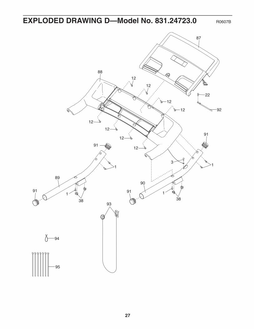
88
87
91
91
12
89
91
1 1
3838
91
90
1
93
12
12
12
12
12
12
12
22
94
95
3
92
1
27
EXPLODED DRAWING D—Model No. 831.24723.0 R0607B

Part No. 252697 R0607B Printed in USA © 2007 ICON IP, Inc.
Your HomeFor repair—in your home—of all major brand appliances, lawn and garden equipment,
or heating and cooling systems, no matter who made it, no matter who sold it!
For the replacement parts, accessories, and user’s manuals that you need to do-it-yourself.
For Sears professional installation of home appliancesand items like garage door openers and water heaters.
1-800-4-MY-HOME® (1-800-469-4663)Call anytime, day or night (U.S.A. and Canada)
www.sears.com www.sears.ca
Our HomeFor repair of carry-in items like vacuums, lawn equipment,
and electronics, call or go on-line for the location of your nearestSears Parts & Repair Center.
1-800-488-1222 Call anytime, day or night (U.S.A. only)www.sears.com
To purchase a protection agreement (U.S.A.)or maintenance agreement (Canada) on a product serviced by Sears:
1-800-827-6655 (U.S.A.) 1-800-361-6665 (Canada)
Para pedir servicio de reparación a domicilio, y para ordenar piezas:
1-888-SU-HOGAR® (1-888-784-6427)
Get it fixed, at your home or ours!
® Registered Trademark / TM Trademark / SM Service Mark of Sears Brands, LLC® Marca Registrada / TM Marca de Fábrica / SM Marca de Servicio de Sears Brands, LLC
90 DAY FULL WARRANTY
If this Sears Treadmill Exerciser fails due to a defect in material or workmanship within 90 days of thedate of purchase, call 1-800-4-MY-HOME® (1-800-469-4663) to arrange for free repair (or replacement ifrepair proves impossible). The incline motor is warranted for 90 days from the date of purchase; thedrive motor is warranted for 5 years from the date of purchase.
This warranty does not apply when the Treadmill Exerciser is used commercially or for rental purposes.
This warranty gives you specific legal rights, and you may also have other rights which vary from state tostate.
Sears, Roebuck and Co., Hoffman Estates, IL 60179