
Worm Gear 58 for Mounting to AC Motors - Bosch Rexroth · 2012-11-02 · 3.1 Ambient Conditions ......
36
Worm Gear 58... for Mounting to AC Motors DOK-GEAR**-58*WORMGEAR-PRJ1-EN-P Project Planning Manual mannesmann Rexroth engineering Indramat 266928
Transcript of Worm Gear 58 for Mounting to AC Motors - Bosch Rexroth · 2012-11-02 · 3.1 Ambient Conditions ......

Worm Gear 58...for Mounting to AC Motors
DOK-GEAR**-58*WORMGEAR-PRJ1-EN-P
Project Planning Manual
mannesmannRexroth
engineering
Indramat266928

Worm Gear 58 ... for Mounting to AC Motors
About this document DOK-GEAR**-58*WORMGEAR-PRJ1-EN-P
Worm Gear 58... for mounting to AC motors
Project Planning Manual
DOK-GEAR**-58*WORMGEAR-PRJ1-EN-P
• 9.564.025.4-01
This document ...
• assists in the selection of a worm gear 58 ...
• helps clarify technical data
• assists in the mechanical integration of the gear into the machine
• helps specify the order information
Document designation ofprevious editions
Status Comments
9.564.025.4-00 March91
1st edition
DOK-GEAR**-58*WORMGEAR-PRJ1-EN-P
June 97 MKD, MDD, MHDmotors included andlayout changed
INDRAMAT GmbH, 1991
Copying this document and giving it to others and the use orcommunication of the contents hereof without express authority, areforbidden. Offenders are liable for the payment of damages. All rightsreserved in the event of a patent or the registration of a utility model ordesign. (DIN 34-1)
All rights are reserved with respect to the content of this documentationand the availability of the product.
INDRAMAT GmbH • Bgm.-Dr.-Nebel-Str. 2 • D-97816 Lohr a. Main
Telefon 09352/40-0 • Tx 689421 • Fax 09352/40-4885
Dept. ENA (JL/UW)
Title
Type of documentation
Document code
Internal file reference
The purpose of this document
Editing sequence
Copyright
Validity
Published by

Worm Gear 58 ... for Mounting to AC Motors
DOK-GEAR**-58*WORMGEAR-PRJ1-EN-P Contents I
Contents
1 Introducing the Product 1-1
2 Dimensioning and Selection 2-12.1 Dimensioning ....................................................................................................................................... 2-1
2.2 Selection .............................................................................................................................................. 2-2
3 Technical Information 3-13.1 Ambient Conditions.............................................................................................................................. 3-1
3.2 Mechanical Features ........................................................................................................................... 3-2
3.3 Power efficiency via speed .................................................................................................................. 3-4
3.4 Possible combinations of worm gear 58... with AC motors ................................................................. 3-4
4 Worm gear 58*3 (Axis Distance 50mm) 4-14.1 Technical Data..................................................................................................................................... 4-1
4.2 Dimensional data 58*3 (Axis distance 50 mm).................................................................................... 4-2
4.3 Permissible shaft load 58*3 (Axis distance 50 mm) ............................................................................ 4-3
4.4 Available Versions ............................................................................................................................... 4-4
5 Worm Gear 58*4 (Axis Distance 63mm) 5-15.1 Technical Data..................................................................................................................................... 5-1
5.2 Dimensional data 58*4 (Axis Distance 63 mm) ................................................................................... 5-2
5.3 Permissible shaft load 58*4 (Axis Distance 63 mm)............................................................................ 5-3
5.4 Available Versions ............................................................................................................................... 5-4
6 Worm Gear 58*5 (Axis Distance 80mm) 6-16.1 Technical Data..................................................................................................................................... 6-1
6.2 Dimensional data 58*5 (Axis Distance 80 mm) ................................................................................... 6-2
6.3 Permissible shaft load58*5 (Axis Distance 80 mm)............................................................................. 6-3
6.4 Available Versions ............................................................................................................................... 6-4
7 Worm Gear 58*6 (Axis Distance 100mm) 7-17.1 Technical Data..................................................................................................................................... 7-1
7.2 Dimensional data 58*6 (Axis Distance 100 mm) ................................................................................. 7-2
7.3 Permissible shaft load58*6 (Axis Distance 100 mm)........................................................................... 7-3
7.4 Available Versions ............................................................................................................................... 7-4
8 Order Information 8-1
9 Service Notes 9-1

Worm Gear 58 ... for Mounting to AC Motors
II Contents DOK-GEAR**-58*WORMGEAR-PRJ1-EN-P
9.1 Contacting Customer Service.............................................................................................................. 9-1
9.2 Fault Report ......................................................................................................................................... 9-2

Worm Gear 58 ... for Mounting to AC Motors
DOK-GEAR**-58*WORMGEAR-PRJ1-EN-P Introducing the Product 1-1
1 Introducing the ProductWorm gear 58... for mounting to AC motors together with INDRAMATdrive controllers create cost-effective automatization systems fornumerous industrical applications.
They are particularly well-suited for use in gear racks or toothed beltdrives in handling systems characterized by high speeds andaccelerations (e.g., loaders and robotics).
Fig. 1-1: Maximum torque ratings - worm gear 58... for mounting to AC motors
Worm gear 58... creates a 90° angle between drive and output shafts.This makes a space-saving and design-friendly construction of handlingsystems possible. The output shaft of the AC motor is connected bymeans of a coupling element with the drive pinion of the worm gear. Thisdrive pinion drives the worm wheel, which is made of a special bronze.This makes a high transmission ratio in a gear wheel stage possible.
• maintenance-free operation resulting from oil lubrication
• can be used even under adverse environmental conditions by meansof a completely closed housing with protection category IP 65
• Low-play gear teeth, which can be adjusted during operations,achieved with the use of ground gear wheel pairs
• low-level noise resulting from worm gear principle
• high dynamics due to low mass to weight ratio
• light weight due to aluminum housing components
Range of applications
Ratings
Functional principle
High operating reliability
High power data

Worm Gear 58 ... for Mounting to AC Motors
1-2 Introducing the Product DOK-GEAR**-58*WORMGEAR-PRJ1-EN-P
• Pinions and belt pulleys directly mounted on the fly because thebearings have been constructed to accomodate high radial loads
• Mounting of output elements of two different types possible:
− non-positive shaft-hub connection by means of plain output hollowshaft
− form-fitting shaft-hub connection through output hollow shaft withkeyway
• The housing design of the gearbox permits mounting to the machine innumerous ways.
Easy mounting

Worm Gear 58 ... for Mounting to AC Motors
DOK-GEAR**-58*WORMGEAR-PRJ1-EN-P Dimensioning and Selection 2-1
2 Dimensioning and Selection
2.1 Dimensioning
Applications which advantageously implement worm gears 58 ... arebroken down into the following characteristic velocity-time diagrams:
• triangular velocity paths with pause intervals
• operation at constant speeds and pause intervals
• operation with trapezoidal velocity paths and pause intervals
These characteristic velocity-time diagrams determine layout criteria.
This mode is typical of all highly dynamic infeed motions as common inroll feed mechanisms in the tin, paper, plastic or packaging industries.
Fig. 2-1: Velocity-time diagram for triangular operations
The layout of this mode is mainly fixed by the required maximum torqueMmax and the effective torque Meff.
This mode is typical of all infeed motions as common in winding devices,roll drives, dosing devices in machines for the tin, paper, plastic orpackaging industries.
Fig. 2-2: Velocity-time diagram for operation at constant speeds
The layout of this mode is mainly fixed by the required constant torqueMdN and the average velocity vmittel or average speed nmittel.
Triangular operation with pauseinterval
Constant velocity with pauseintervals

Worm Gear 58 ... for Mounting to AC Motors
2-2 Dimensioning and Selection DOK-GEAR**-58*WORMGEAR-PRJ1-EN-P
This mode is typical for most infeed motions but especially for loaders andhandling systems as seen in almost all industrial applications.
Fig. 2-3: Velocity-time diagram for trapezoidal operations
The layout of this mode is determined primarily by the required maximumtorque Mmax in the accel phases, the effective torque Meff over the entirecycle time and the average velocity vmittel or average speed nmittel.
2.2 Selection
Selecting the drive, i.e., the suitable motor-gearbox combination,operation with one drive controller means that relevant, drive-determiningvariables must be determined, namely,
• frictional torque
• weight torque
• processing torque
• acceleration torque
• effective torque
• required speed
The motor-gearbox combination operated with one drive controller mustsatisfy the following:
• it must be possible to reach the desired speed
• the continuous torque must exceed effective torque
• intermittent operating torque must exceed the sum of frictional, weightand processing torques
• maximum torque must exceed the sum of frictional, weight andacceleration torques
• the needed runup time must be less than 400 ms
Additionally, note the following about the gearbox:
• • maximum required motor torque must be smaller than themaximum gear input torque
• and maximum reuqired motor speed must be smaller thanmaximum allowable gear-input speed.
Trapezoidal mode with pauseintervals
Drive-determining variables
Layout criteria

Worm Gear 58 ... for Mounting to AC Motors
DOK-GEAR**-58*WORMGEAR-PRJ1-EN-P Technical Information 3-1
3 Technical Information
3.1 Ambient Conditions
The data specified in the selection lists are achieved as follows:
ambient temperature: 0..+45°
installation elevation: 0..1000 meters above sea level
Deviating conditions mean that the data are derated in terms of thediagrams in Fig. 3-1 If both ambient temperature and higher elevationsoccur simultaneously, then multiply the power data with both factors.
Fig. 3-1: Load capacities for higher ambient temperature and installationelevations
As per DIN VDE 0470, section 1 (edition dated 11/92), the AC motor withmounted worm gear 58... is protected by the housing against
• contact with voltage conductive parts or moving parts
• the penetration of extrinsic objects and water.
The protection category is defined in terms of two letters IP (InternationalProtection) and two numbers. The code is IP 65 for AC motors withmounted worm gear 58... .
• for the housing of motor and gear box which are screwed together
• for the output shaft of the gearbox
• for the power and feedback connections of the motor assuming propermounting.
The first number is protection against contact and penetration of objects.The 6 thus means
• protection aaginst penetration of dust
• complete penetration protection.
The second number is the protection against water. Number 5 means
• protection against a jet of water from a nozzle, coming from alldirections against the machine (housing).
The coat is a primary coat. An additional coat with 40µm may be applied.
The primary coat is resistant to
• weathering, yellowing and chalking
• diluted acids and caustic solutions
The primary coat can peel off, however, if frequently steam cleaned.
Worm gears 58...are suited for operating mode S5 (intermittent mode) asper DIN VDE 0530. ON time in this case may not exceed 60%.
Maximum ambient temperature,maximum installation elevation
Protection category
Housing coat
Operating mode

Worm Gear 58 ... for Mounting to AC Motors
3-2 Technical Information DOK-GEAR**-58*WORMGEAR-PRJ1-EN-P
EDT T T
T=
+ +•A B Br
S
100%
ED: ON time in %TA: warm up time in sTB: processing time in sTBr: decel time in sTS: duty cycle time in s
Fig. 3-2: Calculating ON time
The number of cycles may also not exceed 1000 cycles per hour. Onecycle is defined as a duration of the traversing process made up of oneaccel and one decel procedure.
Fig. 3-3: S5 mode (intermittent mode with electronic deceleration)
3.2 Mechanical Features
Fig. 3-4: Permissible mounting orientations
Construction, orientation

Worm Gear 58 ... for Mounting to AC Motors
DOK-GEAR**-58*WORMGEAR-PRJ1-EN-P Technical Information 3-3
The output hollow shaft of worm gears 58... is obtainable in the followingvariations.
• • Plain output hollow shaft (standard)
For nonpositive shaft-hub connections.
This means higher quiet running and a backlash free connection betweenshaft and hub.
Note: We recommend the use of an output hollow shaft with non-positive shaft-hub connections.
Fig. 3-5: Worm gears with plain output hollow shaft
• • Output hollow shaft with keyway per DIN 6885, sh.1 (ed. 8/68)
For form-fitting shaft-hub connections.
This type of connection is suited for torques with a constant direction andlow requirements. The hub must be additionally axially secured. There isa groove for a retaining ring on the gear output hollow shaft.
Fig. 3-6: Worm gear with output hollow shaft with keyway
Note: Plug-in shaft with accessories can be obtained from
ATLANTA Zahnrad- und WerkzeugfabrikEugen Seidenspinner GmbH & CoPostfach 11 61D-74321 Bietigheim-BissingenTel. +49/7142/7001-0
These cannot be purchased from INDRAMAT.
The axial and radial loads must be individually checked when checkinggeneral shaft load. The allowable values are specified in the section„Technical Data“.
Output hollow shaft
Shaft load

Worm Gear 58 ... for Mounting to AC Motors
3-4 Technical Information DOK-GEAR**-58*WORMGEAR-PRJ1-EN-P
3.3 Power efficiency via speed
The power efficiency of worm gears depends on the transmission ratioand gear input speed.
Use the following diagram to estimate relevant power efficiency.
Fig. 3-7: Power efficiency of worm gears via speed
3.4 Possible combinations of worm gear 58... with AC motors
The following table specifies possible combinations.
Gear types Axis distancemm
Motor type
58*3 50 MAC041, MAC063, MAC071, MDD041, MDD065, MDD071
MKD041, MKD071, MHD041, MHD071
58*4 63 MAC063, MAC071, MAC0902), MAC092, MAC095, MAC114
MDD065, MDD071, MDD 0901)2), MKD071, MKD090, MHD071
58*5 80 MAC0902), MAC0932), MAC095, MAC112, MAC114, MAC117
MDD0901)2), MDD0931)2), MDD1121)3), MKD090, MKD112, MHD112
58*6 100 MAC0902), MAC0932), MAC095, MAC1123), MAC114, MAC1153),
MAC117, MDD0901)2), MDD0931)2), MDD1121)3), MDD1151)3)
MKD090, MKD112, MHD1121) Liquid-cooled motors may not be combined.2) Only with center diameter Ø 110 mm3) Only with center diameter Ø 130 mm
Fig. 3-8: Possible combinations of worm gear 58... with AC motors
Note: In order to be able to mount the worm gears to the motors, it isnecessary that they have plain output shafts.

Worm Gear 58 ... for Mounting to AC Motors
DOK-GEAR**-58*WORMGEAR-PRJ1-EN-P Worm gear 58*3 (Axis Distance 50mm) 4-1
4 Worm gear 58*3 (Axis Distance 50mm)
4.1 Technical Data
Designation Symbol Unit 58*3
Tranmission ratioi - 6.75 9.25 14.5 19.5 39.0 50.0
Maximum inputspeed 1) nin min-1 3000 3000 3000 3000 3000 3000
Maximum inputtorque 2) Min,max Nm 7.5 5.7 4.2 2.7 1.8 1.8
Maximum outputspeed nout min-1 444 324 207 154 77 60
Maximum outputtorque 2) Mout,max Nm 46 47 50 43 50 40
Power efficiency atstandstill ηo % 69 68 59 57 38 30
Power efficiencynin = 1500 min-1 η % 91 89 83 81 70 64
Moment of inertia 3) J kgcm2 1.26 1.20 1.13 1.05 1.08 1.06
Torsional stiffness 4) D Nm/rad 52000 52000 52000 52000 52000 520001) Theoretically possible gear-input speed2) Available for a maximum of 400ms3) Mass moment of inertia of gear including the coupling unit to the motor as relates to the gear input side4) Torsional stiffness of the gear in terms of the gear output side with fixed gear input side
Fig. 4-1: Transmission-dependent data
Designation Symbol Unit 58*3
torsional play 1) ∆ϕ arcmin ≤ 3service life L10h h 30000
lubricant - oil
allowable ambienttemperature TUm °C 0...45
noise level Lp dB(A) <70
protection category - IP 65
weight m kg 8
mounting to see section 3.41) relates to gear output side with 2% gear nominal output torque and fixed
gear input side
Fig. 4-2: General data
Transmission-dependent data
General data

Worm Gear 58 ... for Mounting to AC Motors
4-2 Worm gear 58*3 (Axis Distance 50mm) DOK-GEAR**-58*WORMGEAR-PRJ1-EN-P
4.2 Dimensional data 58*3 (Axis distance 50 mm)
Fig. 4-3: Dimensional data 58*3 (axis distance 50 mm)

Worm Gear 58 ... for Mounting to AC Motors
DOK-GEAR**-58*WORMGEAR-PRJ1-EN-P Worm gear 58*3 (Axis Distance 50mm) 4-3
4.3 Permissible shaft load 58*3 (Axis distance 50 mm)
Fig. 4-4: Explanation of the variables influencing permissible shaft load
Fig. 4-5: Permissible radial force
FA = 1800 NFig. 4-6: Permissible axis force
Permissible radial force
Permissible axis force

Worm Gear 58 ... for Mounting to AC Motors
4-4 Worm gear 58*3 (Axis Distance 50mm) DOK-GEAR**-58*WORMGEAR-PRJ1-EN-P
4.4 Available Versions
Fig. 4-7: Available versions of 58*3 depictured in terms of type codes

Worm Gear 58 ... for Mounting to AC Motors
DOK-GEAR**-58*WORMGEAR-PRJ1-EN-P Worm Gear 58*4 (Axis Distance 63mm) 5-1
5 Worm Gear 58*4 (Axis Distance 63mm)
5.1 Technical Data
Designation Symbol Unit 58*4
Transmission ratioi - 6.75 9.25 14.5 19.5 39.0
Maximum inputspeed1) nin min-1 3000 3000 3000 3000 3000
Maximum inputtorque 2) Min,max Nm 19.5 10.8 9.9 6.8 4.5
Maximum outputspeed nout min-1 444 324 207 154 77
Maximum outputtorque 2) Mout,max Nm 120 90 120 110 127
Power efficiency atstandstill ηo % 69 68 59 57 38
Power efficiency atnin = 1500 min-1 η % 91 90 84 83 73
Moment of inertia 3) J kgcm2 4.0 3.61 3.59 3.32 3.64
Torsional stiffness 4) D Nm/rad 115000 115000 115000 115000 1150001) Theoretically possible gear input speed2) Available for a maximum of 400 ms3) Mass moment of inertia of gear including coupling unit to motor in terms of gear input side4) Torsional stiffness of the gear in terms of gear output side with fixed gear input side
Fig. 5-1: Transmission-Dependent Data
Designation Symbol Unit 58*4
Torsional play 1) ∆ϕ arcmin ≤ 3Service life L10h h 30000
Lubricant - Oil
permissible ambienttemperature TUm °C 0...45
Noise level Lp dB(A) <70
Protection category - IP 65
Weight m kg 13
Mounting for See section3.41) in terms of gear output side with 2% gear nominal output torque and fixed
gear input sideFig. 5-2: General data
Transmission-Dependent Data
General data

Worm Gear 58 ... for Mounting to AC Motors
5-2 Worm Gear 58*4 (Axis Distance 63mm) DOK-GEAR**-58*WORMGEAR-PRJ1-EN-P
5.2 Dimensional Data 58*4 (Axis Distance 63 mm)
Fig. 5-3: Dimensional data 58*4 (Axis distance 63 mm)

Worm Gear 58 ... for Mounting to AC Motors
DOK-GEAR**-58*WORMGEAR-PRJ1-EN-P Worm Gear 58*4 (Axis Distance 63mm) 5-3
5.3 Permissible shaft load 58*4 (Axis Distance 63 mm)
Fig. 5-4: Explanation of the variables influencing permissible shaft load
Fig. 5-5: Permissible radial force
FA = 2500 NFig. 5-6: Permissible axial force
Permissible radial force
Permissible axial force

Worm Gear 58 ... for Mounting to AC Motors
5-4 Worm Gear 58*4 (Axis Distance 63mm) DOK-GEAR**-58*WORMGEAR-PRJ1-EN-P
5.4 Available Versions
Fig. 5-7: Available versions 58*4 depicted using type codes
Worm Gear 58 ... for Mounting to AC Motors
DOK-GEAR**-58*WORMGEAR-PRJ1-EN-P Worm Gear 58*5 (Axis Distance 80mm) 6-1
6 Worm Gear 58*5 (Axis Distance 80mm)
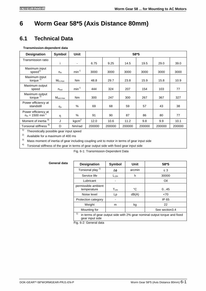
6.1 Technical Data
Designation Symbol Unit 58*5
Transmission ratioi - 6.75 9.25 14.5 19.5 29.0 39.0
Maximum inputspeed1) nin min-1 3000 3000 3000 3000 3000 3000
Maximum inputtorque 2) Min,max Nm 48.8 29.7 23.8 15.9 15.8 10.9
Maximum outputspeed nout min-1 444 324 207 154 103 77
Maximum outputtorque 2) Mout,max Nm 300 247 300 267 367 327
Power efficiency atstandstill ηo % 69 68 59 57 43 38
Power efficiency atnin = 1500 min-1 η % 91 90 87 86 80 77
Moment of inertia 3) J kgcm2 12.0 10.6 11.2 9.8 9.9 10.1
Torsional stiffness 4) D Nm/rad 200000 200000 200000 200000 200000 2000001) Theoretically possible gear input speed2) Available for a maximum of 400 ms3) Mass moment of inertia of gear including coupling unit to motor in terms of gear input side4) Torsional stiffness of the gear in terms of gear output side with fixed gear input side
Fig. 6-1: Transmission-Dependent Data
Designation Symbol Unit 58*5
Torsional play 1) ∆ϕ arcmin ≤ 3Service life L10h h 30000
Lubricant - Oil
permissible ambienttemperature TUm °C 0...45
Noise level Lp dB(A) <70
Protection category - IP 65
Weight m kg 22
Mounting for See section3.41) in terms of gear output side with 2% gear nominal output torque and fixed
gear input sideFig. 6-2: General data
Transmission-dependent data
General data

Worm Gear 58 ... for Mounting to AC Motors
6-2 Worm Gear 58*5 (Axis Distance 80mm) DOK-GEAR**-58*WORMGEAR-PRJ1-EN-P
6.2 Dimensional Data 58*5 (Axis Distance 80 mm)
Fig. 6-3: Dimensional data 58*5 (Axis Distance 80 mm)

Worm Gear 58 ... for Mounting to AC Motors
DOK-GEAR**-58*WORMGEAR-PRJ1-EN-P Worm Gear 58*5 (Axis Distance 80mm) 6-3
6.3 Permissible shaft load58*5 (Axis Distance 80 mm)
Fig. 6-4: Explanation of the variables influencing permissible shaft load
Fig. 6-5: Permissible radial force
FA = 4000 NFig. 6-6: Permissible axial force
Permissible radial force
Permissible axial force
Worm Gear 58 ... for Mounting to AC Motors
6-4 Worm Gear 58*5 (Axis Distance 80mm) DOK-GEAR**-58*WORMGEAR-PRJ1-EN-P
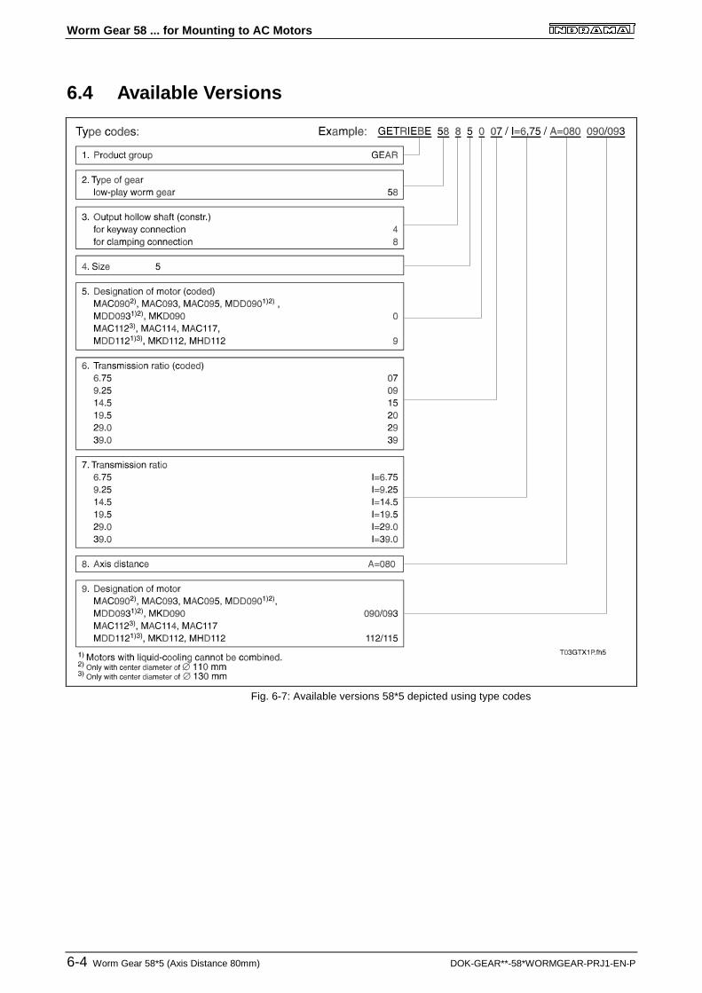
6.4 Available Versions
Fig. 6-7: Available versions 58*5 depicted using type codes

Worm Gear 58 ... for Mounting to AC Motors
DOK-GEAR**-58*WORMGEAR-PRJ1-EN-P Worm Gear 58*6 (Axis Distance 100mm) 7-1
7 Worm Gear 58*6 (Axis Distance 100mm)
7.1 Technical Data
Designation Symbol Unit 58*5
Transmission ratioi - 6.75 9.25 14.5 19.5 39.0
Maximum inputspeed1) nin min-1 3000 3000 3000 3000 3000
Maximum inputtorque 2) Min,max Nm 80.5 59.4 47.6 35.4 22.4
Maximum outputspeed nout min-1 444 324 207 154 77
Maximum outputtorque 2) Mout,max Nm 500 500 600 600 700
Power efficiency atstandstill ηo % 69 68 59 57 38
Power efficiency atnin = 1500 min-1 η % 92 91 87 87 80
Moment of inertia 3) J kgcm2 18.8 14.0 13.1 11.3 14.3
Torsional stiffness 4) D Nm/rad 340000 340000 340000 340000 3400001) Theoretically possible gear input speed2) Available for a maximum of 400 ms3) Mass moment of inertia of gear including coupling unit to motor in terms of gear input side4) Torsional stiffness of the gear in terms of gear output side with fixed gear input side
Fig. 7-1: Transmission-Dependent Data
Designation Symbol Unit 58*6
Torsional play 1) ∆ϕ arcmin ≤ 3Service life L10h h 30000
Lubricant - Oil
Permissible ambienttemperature TUm °C 0...45
Noise level Lp dB(A) <70
Protection category - IP 65
Weight m kg 33
Mounting for See section3.41) in terms of gear output side with 2% gear nominal output torque and fixed
gear input sideFig. 7-2: General data
Transmission-dependent data
General data

Worm Gear 58 ... for Mounting to AC Motors
7-2 Worm Gear 58*6 (Axis Distance 100mm) DOK-GEAR**-58*WORMGEAR-PRJ1-EN-P
7.2 Dimensional Data 58*6 (Axis Distance 100 mm)
Fig. 7-3: Dimensional data 58*6 (Axis distance 100 mm)

Worm Gear 58 ... for Mounting to AC Motors
DOK-GEAR**-58*WORMGEAR-PRJ1-EN-P Worm Gear 58*6 (Axis Distance 100mm) 7-3
7.3 Permissible Shaft Load 58*6 (Axis Distance 100 mm)
Fig. 7-4: Explanation of the variables influencing permissible shaft load
Fig. 7-5: Permissible radial force
FA = 5000 NFig. 7-6: Permissible axial force
Permissible radial force
Permissible axial force

Worm Gear 58 ... for Mounting to AC Motors
7-4 Worm Gear 58*6 (Axis Distance 100mm) DOK-GEAR**-58*WORMGEAR-PRJ1-EN-P
7.4 Available Versions
Fig. 7-7: Available versions 58*6 depicted using type codes

Worm Gear 58 ... for Mounting to AC Motors
DOK-GEAR**-58*WORMGEAR-PRJ1-EN-P Order Information 8-1
8 Order InformationThe worm gear must be specified as a sub-item of the AC motor . Acomplete unit is always delivered made up of a worm gear 58... and anAC motor.
When ordering the motor, also note that the motor output shaft must be aplain shaft and the center diameter must equal
MAC/MDD 090/093, Ø 110 mm,MAC/MDD 112/115, Ø 130 mm.
Order example:
1 1 AC Motor
type: MKD 090B-047-GG0
1.1 1 Worm Gear
type: GETRIEBE 58 8 5 0 07/I=6.75/A=080 090/093
mounted to item 1
Worm Gear 58 ... for Mounting to AC Motors
8-2 Order Information DOK-GEAR**-58*WORMGEAR-PRJ1-EN-P
Notes

Worm Gear 58 ... for Mounting to AC Motors
DOK-GEAR**-58*WORMGEAR-PRJ1-EN-P Service Notes 9-1
9 Service Notes
9.1 Contacting Customer Service
During usual European office hours INDRAMAT customer service can bereached through your nearest Indramat Customer Service Office.Outside of usual office hours, help can be obtained via the followingService Hotline numbers at the hours specified below:
Service HotlineTel. 0172 - 660 040 6 or 0171 - 333 882 6
Monday - Friday 17 00 - 23 00 CET
Saturday 8 00 - 20 00 CET
Sunday and holidays 9 00 - 19 00 CET
To ensure a quick elimination of the problems and faults, please make anote of the following information before contacting INDRAMAT customerservice, namely,
• the type designations of controller, motor and gearbox
• the fault state
• any fault and diagnostic displays.
When returning the gears, please include the Fault Report included in thisdocument. It can be found in section 9.2 and can be copied. It will helplocate the problems.

Worm Gear 58 ... for Mounting to AC Motors
9-2 Service Notes DOK-GEAR**-58*WORMGEAR-PRJ1-EN-P
9.2 Fault Report
Fig. 9-1: Fault Report

Worm Gear 58 ... for Mounting to AC Motors
DOK-GEAR**-58*WORMGEAR-PRJ1-EN-P Customer Service Directory
Directory of Customer Service LocationsGermany
Sales region central
INDRAMAT GmbHD-97816 Lohr am MainBgm.-Dr.-Nebel-Str. 2
Telefon: 09352/40-0Telefax: 09352/40-4885
Sales region east
INDRAMAT GmbHD-09120 ChemnitzBeckerstraße 31
Telefon: 0371/3555-0Telefax: 0371/3555-230
Sales region West
INDRAMAT GmbHD-40849 RatingenHansastraße 25
Telefon: 02102/4318-0Telefax: 02102/41315
Sales region north
INDRAMAT GmbHD-22085 HamburgFährhausstraße 11
Telefon: 040/227126-16Telefax: 040/227126-15
Sales region south
INDRAMAT GmbHD-80339 MünchenRidlerstraße 75
Telefon: 089/540138-30Telefax: 089/540138-10
Sales region southwest
INDRAMAT GmbHD-71229 LeonbergBöblinger Straße 25
Telefon: 07152/972-6Telefax: 07152/972-727
INDRAMAT Service-Hotline
INDRAMAT GmbHTelefon: D-0172/660 040 6
-or-
Telefon: D-0171/333 882 6
Customer Service locations in Germany
EuropeAustria
G.L.Rexroth Ges.m.b.H.Geschäftsbereich INDRAMATA-1140 WienHägelingasse 3
Telefon: 1/9852540-400Telefax:1/9852540-93
Austria
G.L.Rexroth Ges.m.b.H.Geschäftsbereich INDRAMATA-4061 PaschingRandlstraße 14
Telefon: 07229/4401-36Telefax: 07229/4401-80
Belgium
Mannesmann Rexroth N.V.-S.A.Geschäftsbereich INDRAMATB-1740 TernatIndustrielaan 8
Telefon: 02/5823180Telefax: 02/5824310
Denmark
BEC Elektronik ASDK-8900 RandersZinkvej 6
Telefon: 086/447866Telefax: 086/447160
England
Mannesmann Rexroth Ltd.INDRAMAT DivisionCirencester, Glos GL7 1YG4 Esland Place, Love Lane
Telefon: 01285/658671Telefax: 01285/654991
Finnland
Rexroth Mecman OYSF-01720 VantaaRiihimiehentie 3
Telefon: 0/848511Telefax: 0/846387
France
Rexroth - Sigma S.A.Division INDRAMATF-92632 Gennevilliers CedexParc des Barbanniers 4,Place du Village
Telefon: 1/41475430Telefax: 1/47946941
France
Rexroth - Sigma S.A.Division INDRAMATF-69634 Venissieux - Cx91, Bd 1 Joliot Curie
Telefon: 78785256Telefax: 78785231
France
Rexroth - Sigma S.A.Division INDRAMATF-31100 Toulouse270, Avenue de lardenne
Telefon: 61499519Telefax: 61310041
Italy
Rexroth S.p.A.Divisione INDRAMATI-20063 Cernusco S/N.MIVia G. Di Vittoria, 1
Telefon: 02/92365-270Telefax: 02/92108069
Italy
Rexroth S.p.A. DivisioneINDRAMATVia Borgomanero, 11I-10145 Torino
Telefon: 011/7712230Telefax: 011/7710190
Netherlands
Hydraudyne Hydrauliek B.V.Kruisbroeksestraat 1aP.O. Box 32NL-5280 AA Boxtel
Telefon: 04116/51951Telefax: 04116/51483
Spain
Rexroth S.A.Centro Industrial SantiagoObradors s/nE-08130 Santa Perpetua deMogoda (Barcelona)
Telefon: 03/718 68 51Telex: 591 81Telefax: 03/718 98 62
Spain
Goimendi S.A.División IndramatJolastokieta (Herrera)Apartado 11 37San Sebastion, 20017
Telefon: 043/40 01 63Telex: 361 72Telefax: 043/39 93 95
Sweden
AB Rexroth MecmanINDRAMAT DivisionVaruvägen 7S-125 81 Stockholm
Telefon: 08/727 92 00Telefax: 08/64 73 277
Switzerland
Rexroth SADépartement INDRAMATChemin de l`Ecole 6CH-1036 Sullens
Telefon: 021/731 43 77Telefax: 021/731 46 78
Switzerland
Rexroth AGGeeschäftsbereich INDRAMATGewerbestraße 3CH-8500 Frauenfeld
Telefon: 052/720 21 00Telefax: 052/720 21 11
Russia
Tschudnenko E.B.Arsenia 22153000 IvanovoRußland
Telefon: 093/22 39 633
European customer service locations without Germany

Worm Gear 58 ... for Mounting to AC Motors
Customer Service Directory DOK-GEAR**-58*WORMGEAR-PRJ1-EN-P
Outside of EuropeArgentina
Mannesmann Rexroth S.A.I.C.Division INDRAMATAcassusso 48 41/71605 Munro (Buenos Aires)Argentina
Telefon: 01/756 01 40 01/756 02 40Telex: 262 66 rexro arTelefax: 01/756 01 36
Argentina
NakaseAsesoramiento TecnicoDiaz Velez 29291636 Olivos(Provincia de Buenos Aires)ArgentinaArgentina
Telefon 01/790 52 30
Australia
Australian Industrial MacheneryServices Pty. Ltd.Unit 3/45 Horne STCampbellfield VIC 2061Australia
Telefon: 03/93 59 0228Telefax: 03/93 59 02886
Brazil
Mannesmann Rexroth AutomaçãoLtda.Divisão INDRAMATRua Georg Rexroth, 609Vila Padre AnchietaBR-09.951-250 Diadema-SPCaixa Postal 377BR-09.901-970 Diadema-SP
Telefon: 011/745 90 65 011/745 90 70Telefax: 011/745 90 50
Canada
Basic Technologies CorporationBurlington Division3426 Mainway DriveBurlington, OntarioCanada L7M 1A8
Telefon: 905/335-55 11Telefax: 905/335-41 84
China
Rexroth (China) Ldt.Shanghai OfficeRoom 206Shanghai Intern. Trade Centre2200 Yanan Xi LuShanghai 200335P.R. China
Telefon: 021/627 55 333Telefax: 021/627 55 666
China
Rexroth (China) Ldt.Shanghai Parts & Service Centre199 Wu Cao Road, Hua CaoMinhang DistrictShanghai 201 103P.R. China
Telefon: 021/622 00 058Telefax: 021/622 00 068
China
Rexroth (China) Ldt.1430 China World Trade Centre1, Jianguomenwai AvenueBeijing 100004P.R. China
Telefon: 010/50 50 380Telefax: 010/50 50 379
China
Rexroth (China) Ldt.A-5F., 123 Lian Shan StreetSha He Kou DistrictDalian 116 023P.R. China
Telefon: 0411/46 78 930Telefax: 0411/46 78 932
Honkong
Rexroth (China) Ldt.19 Cheung Shun Street1st Floor, Cheung Sha Wan,Kowloon, Honkong
Telefon: 741 13 51/-54 und 741 14 30Telex: 3346 17 GL REX HXTelefax: 786 40 19 786 07 33
India
Mannesmann Rexroth (India) Ltd.INDRAMAT DivisionPlot. 96, Phase IIIPeenya Industrial AreaBangalore - 560058
Telefon: 80/839 21 01 80/839 73 74Telex: 845 5028 RexBTelefax: 80/839 43 45
Japan
Rexroth Co., Ltd.INDRAMAT DivisionI.R. BuildingNakamachidai 4-26-44Tsuzuki-ku, Yokohama 226Japan
Telefon: 045/942-72 10Telefax: 045/942-03 41
Korea
Rexroth-Seki Co Ltd.1500-12 Da-Dae-DongSaha-Gu, Pusan, 604-050
Telefon: 051/264 90 01Telefax: 051/264 90 10
Korea
Seo Chang Corporation Ltd.Room 903, Jeail Building44-35 Yoido-DongYoungdeungpo-KuSeoul, Korea
Telefon: 02/780-82 07 ~9Telefax: 02/784-54 08
Mexico
Motorización yDiseño de Controles, S.A. de C.V.Av. Dr. Gustavo Baz No. 288Col. Parque Industrial la IomaApartado Postal No. 31854060 TlalnepantlaEstado de Mexico
Telefon: 5/397 86 44Telefax: 5/398 98 88
USA
Rexroth CorporationINDRAMAT Division5150 Prairie Stone ParkwayHoffman Estates, Illinois 60192
Telefon: 847/645-36 00Telefax: 857/645-62 01
USA
Rexroth CorporationINDRAMAT Division2110 Austin AvenueRochester Hills, Michigan 48309
Telefon: 810/853-82 90Telefax: 810/853-82 90
Customer Service locations outside of Europe

Worm Gear 58 ... for Mounting to AC Motors
DOK-GEAR**-58*WORMGEAR-PRJ1-EN-P
Notes

Indramat