riduttori e motoriduttori a vite worm gear reducers and gearmotors


Worm Gear Reducers and Gear Motors SERIES WPalaDrive
PalaDrive Series MHelical Gearmotors
PalaDrive Series CHelical WormGearmotors
PalaDrive Series FParallel Helical ShaftMounted
PalaDrive Series KRight Angle Helical BevelGearmotors
PalaDrive Series AWorm Gearmotors
PalaDriveCustom Gear
PalaDriveCustom Gear
PIV Gearunits andReplacement Chains
PalaDriveST Variator
PalaDrive NMRVWorm Gear
PalaDrive Parallel ShaftMount Reducer
PalaDrive PlanetaryGearbox
PalaDrive Shaft Mounted Reducers PalaFlexKR Coupling
PalaFlexGear Sleeve Coupling
PalaFlexChain Coupling
PalaFlexPin & Bush Coupling
PalaFlexTaper Grid Coupling
PalaFlexGear Coupling
PalaFlexDisc Coupling
Kop-FlexElastomeric Coupling
Kop-Flex Series HGear Coupling
Kop-FlexFasts Gear Coupling
Kop-FlexWaldron Flexalign GearCoupling
Kop-FlexKD Disc Coupling
RotofluidFluid Coupling
SurfaLocShaft Locking Device
PalaFlexQD Bush
PalaFlexSplit Taper Bush
Taper TiteBushing
Taper TitePulleys
Taper TiteTiming Pulley
PalaFlaxChain Drives
Power Twist PlusV section Link Belt
Super T LinkWedge section Link Belt
Serving a great quality and high efficiency of gear drives, transmission components, electric motors, variable speed drives, starting
and stopping assisting devices, linear motion system and motion control system. Palawatr make your demand better beyond
expectation.
PalaFlexChain Drives
Products in the range

Serving a great quality and high efficiency of gear drives, transmission components, electric motors, variable speed drives, starting
and stopping assisting devices, linear motion system and motion control system. Palawatr make your demand better beyond
expectation.
SafeguardTorque Limiter
Siemens Energy-saving motors eff1,Improved Efficiency eff2, EPACT, Pole-change MotorsFor converter-fed operation
SlemensCOMBIMASTERMotor with converter
Siemens IncreasedSafety EEx e ll motors
Siemens Explosion-proofEnclosure EEx de llCMotors
Siemens ModularConcept Motors
Siemens Solution Motors,Smoke extraction motors,Marine motors
SiemensMicromaster 440Inverters
SiemensMicromaster 420Inverters
Siemens Sinamics G110Inverters
Siemens Profibus moduleDevicenet moduleEncoder module
Vibrating Motor KENDRION BinderFail-safe Brake
Galvi Drum and DiskBrakes
Emerson Servo motors,Drives and Controllers
Bayside PrecisionGearheads
Micro Slides PrecisionLinear Stage
SBC Cam Clutch andBack Stop
Hepco DLSLinear Transmission &Positioning System
Hepco PDU2Aluminium Profile DrivenUnit
Hepco HDSHeavy Duty Slide System
Hepco RTSRing Slides & TrackSystem
Hepco DTSDriven Track System
Hepco HDLSHeavy Duty Driven LinearSystem
Hepco GV3Linear Guidance andTransmission System
Hepco SL2Stainless Steel BasedSlide System
Hepco MCSAluminium Frame andMachine ConstructionSystem
Hepco Dual-VeeSingle Edge SlideSystem
Products in the range
Worm Gear Reducers and Gear Motors SERIES WPalaDrive

Worm Gear Reducers and Gear Motors SERIES WPalaDrive
1
with worm gear pair
with 1 cylindrical gear pair plus worm
with worm gear pair
with 1 cylindrical gear pair plus worm
with 2 cylindrical gear pairs plus worm

2
(worm)
(worm)
(worm wheel)
12
Size : double row angular contact ball bearing plus ball bearing.For MW 011, 021 with motor size 63 and 71, MW 031 with motor size 71 and 80, MW 041...071with motor 80 and 90 motor flange is usually integral with casing.
(01 ... 07)
(08 ... 12)
(01 ... 07)
(08 ... 12)
(01 ... 07)
(08 ... 12)
(02 ... 07)
(08 ... 10)
(01 ... 07)
(08 ... 12)
Worm Gear Reducers and Gear Motors SERIES WPalaDrive

33
1. Symbols and units of measure
1. Symbols and units of measurey
Symbols used in the catalogue and formulae, in alphabetical order,with relevant units of measure.
Symbol Definition Units of measure Notes
In the In the formulaecatalogue
Technical System SI1) System
dimensions mm -a acceleration - m/s 2
d diameter - mf frequency Hz Hzfs service factorf t thermal factorF force - kgf N 2) 1 kgf ≈ 9,81 N ≈ 0,981 daNFr radial load daN -Fa axial load daN -g acceleration of gravity - m/s2 normal value 9,81 m/s2
G weight (weight force) - kgf NGd 2 dynamic momen - kgf m 2 -
i transmission ratio i =
I electric current - AJ moment of inertia kg m 2 - kg m2
Lh bearing life h -m mass kg kgf s2/m kg3)
M ≈ 9,81 N m ≈ 0,981 daN m
n speed min-1 giri/min - 1 min-1 ≈ 0,105 rad/srev/minP power kW CV W 1 CV ≈ 736 W ≈ 0,736 kWP t thermal power kW -r radius - m
R variation ratio R =
s distance - mt Celsius temperature oC -t time s s
min 1 min = 60 sh 1 h = 60 min = 3 600 sd 1 d = 24 h = 86 400 s
U voltage V Vv velocity - m/sW work, energy MJ kgf m J4)
z frequency of starting avv./h -starts/h angular acceleration - rad/s2
efficiency
s static efficiency friction coefficient plane angle o rad 1 giro = 2 rad 1 rev = 2 rad
1∞= rad180
angular velocity - - rad/s 1 rad/s ≈ 9,55 min-1
n2 max
n2 min
n1
n2
Additional indexes and other signs
Ind Definition
max maximummin minimumN nominal1 rrelating to high speed shaft (input)2 rrelating to low speed shaft (output)
from ... to≈ approximately equal to
greater than or equal toless than or equal to
1) SI are the initials of the International Unit System, defined and approved by theGeneral Conference on Weights and Measures as the only system of units of measure.Ref. CNR UNI 10 003-84 (DIN 1 301-93 NF X 02.004, BS 5 555-93, ISO 1 000-92).UNI: Ente Nazionale Italiano di Unificazione.DIN: Deutscher Normenausschuss (DNA).NF: Association FranÁaise de Normalisation (AFNOR).BS: British Standards Institution (BSI).ISO: International Organization for Standardization.
2) Newton [N] is the force imparting an acceleration of 1 m/s2 to a mass of 1 kg.3) Kilogramme [kg] is the mass of the prototype kept at SËvres (i.e. 1 dm3 of distilled
4) Joule [J] is the work done when the point of application of a force of 1 N is displacedthrough a distance of 1 m.
o
Worm Gear Reducers and Gear Motors SERIES WPalaDrive

4
01 ... 07
08 ... 14
Universal mounting having feet integral with casing on 3 f ac es(s izes 0 1 ..0 7 ) or on 2 f ac es (s izes 0 8 ...14 ) and B14 flange on2 f ac es. Design and st rengt h of t he c asing per mit interesting shaftmounting solutionsThickened size and performance gradation ( some sequent ials izes are obt ained w it h t he same c asing and many c omponent s inc ommon)
High, reliable and tested performances (Ni bronze); optimiza-tion of worm gear pair performances (ZI involute profile andadequately conjugate worm wheel profile)Compactness, standardized dimensions and compliance withstandardsIEC standardized motor
Rigid and precise cast iron monolithic casingGenerous internal space between train of gears and casing allowing:– high oil c apac it y;– low er oil pollut ion;– great er durat ion of w or m w heel and w or m bear ings ;– low er running t emperat ure.
Possibility of fitting particularly powerful motors and transmit-ting high nominal and maximum torquesImproved and up-graded modular construction both for com-ponent parts and assembled product which ensures manufac-turing and product management flexibilityHigh manufacturing quality standardPossibility of obtaining multiple drives and at synchronous speedWide design and acccessory availability: shaft -mount ing arrange-ment s, mixed keying syst ems w it h key and loc king element s ( r ings for s izes 0 1 ...0 3 , bush f or s izes 0 4 ...14 ) , square flanges for servo-motors and hub c lamp, reduced backlash, et c .
Reduced maintenanceA c ombinat ion of moder n c onc ept s, analyt ic al c alc ulat ions c arr ied outon each single part, use of t he ver y lat est mac hine t ools , plus syst e-mat ic c hec ks on mat erials , assembling and w orkmanship, gives t hisseries of gear reduc ers high efficiency, running precision, regularmot ion and noiselessness, constant per for manc es, life and reliabi-lity, st rengt h and overload w it hst anding and suit abilit y for heaviestapplications, w ide size and rat io range, exc ellent servic e - the ad-vantages typically associated with high quality worm gear redu-cers produced in large series.
2. Specifications
2. Specifications
Worm Gear Reducers and Gear Motors SERIES WPalaDrive

5
2. Specifications
a - Gear reducerStructural featuresMain specifications are: universal mounting having feet integral with casing (lower,
upper feet and vertical on the face opposite to motor for sizes01... 07; lower and upper feet for sizes 08 ... 14) and B14 flange(integral with casing for sizes 01 ... 03) on 2 faces of hollow lowspeed shaft output. B5 flange with spigot recess which can bemounted onto B14 flanges (see chap. 17). Design and strength ofthe casing permit interesting shaft mounting solutions;
tickened size (10 sizes with 4 size pairs with final centre distance01 ... 14) and performance gradation; the size pairs are obtainedwith the same casing and with many components in common;gear reducer structure sized so as to accept particularly powerfulmotors both MW 1 and MW 2 and to permit the transmissionof high nominal and maximum torques at low output speeds, thisbeing the particular advantage of worm gear pairs;gearmotor sizes 02... 10 with 2 cylindrical coaxial gear pair firststage in order to obtain high reversible and irreversible transmission ratios with standardized motor (63 ... 112) in a com-pact and economy way;normally, gearmotors MW 1 sizes 01, 02 (with motor sizes 63 and71) 03 (with motor sizes 71 and 80) and 04 ... 07 (with motor sizes80 and 90) have motor flange integral with the casing;hollow low speed shaft with keyway, and (sizes 04 ... 14) with cir-clip groove for removal purposes: in spheroidal cast iron (greycast iron for sizes 01 and 02) integral with wormwheel (sizes 01 ...12) or steel (sizes 13 and 14); standard (left or right extension)or double extension low speed shaft (see ch. 17).gear reducers: input face with machined surface W1 or flangeW2 and with fixing holes: wormshaft end with key, and reducedwormshaft end with circlip groove (the same as for W 2 , MW 2 ,MW3, MW 111 ... 141 with coupling);gearmotors: IEC standardized motor directly keyed into theworm (MW1), for motor sizes 200 ... 250 patented keying systemto obtain easier installing and removing and avoid fretting corro-sion; standardized motor with pinion directly mounted onto theshaft end (MW2 , MW3);
fan cooling (sizes 08 ...14); use of double extension worm-shaftsimply obtained by removing the fan cowl centre disc; for MW071with motor 100 and 112, fan incorporated in motor mounting flange;bearings on worm: double row angular contact ball bearing plusball bearing (size 01); face-to-face taper roller bearings (sizes 02... 12); paired back-to-back taper roller bearings plus one ballbearing (sizes 13 and 14);bearings on wormwheel: ball bearings (sizes 01 ... 11); taper rol-ler bearings (sizes 12 ... 14);200 UNI ISO 185 cast iron monolithic casing with transversestiffening ribs, and high oil capacity;oil bath lubrication with synthetic oil (ch. 16) for «long-life» lubri-cation: units provided with one plug (sizes 01 ... 05) or two plugs(sizes 06 and 07) supplied filled with oil; with filler plug withvalve, drain plug and level plug (sizes 08 ... 14) suppliedwithout oil; sealed;paint: external coating in epoxy powder paint (sizes 01 ... 07) or insynthetic paint (sizes 08... 14) appropriate for resistance tonormal industrial environments and suitable for the application offurther coats of synthetic paint; colour blue RAL 5010 DIN 1843;internal protection in epoxy powder paint (sizes 01 ... 07) or inepoxy resin paint (sizes 08 ... 14) appropriate for resistance tosynthetic oils;possibility of obtaining combined gear reducer and gearmotorunits providing high transmission ratios with different train of gearsdepending on overall dimension, efficiency, and final outputspeed requirements.
01 02 03 04 05 06 07 08 09 10 11 12 13 14
Worm Gear Reducers and Gear Motors SERIES WPalaDrive

6
2. Specifications
– worm gear pair; 1 cylindrical gear pair plus worm; with 2 cylindri-cal gear pairs plus worm gear pair (gearmotor only);
– worm gear pairs, with transmission ratios ( = 10... 63) for the different sizes; = for MR V 32 ... 81;
– 10 sizes having 4 sizes pairs (standard and strengthened) with finalreduction centre distance to R 10 series (01... 14) for a total of
;– nominal transmission ratios to R 10 series (01... 14; up to 16 000 for
combined units);– casehardened and hardened cylindrical worm in 16 CrNi4 or
20 MnCr5 UNI 7846-78 steel (depending on size) with ground andprofile ;
– wormwheel with profile especially conjugate to the worm throughhob optimization, with hub in spheroidal or grey cast iron (depen-ding on size) and CuSn12Ni2-B (EN1982-98) gear rimwith high pureness and controlled phosphor contents;
– casehardened and hardened cylindrical gear pair in 16CrNi4 UNI7846-78 steel with ground profile and helical toothing;
– train of gear load capacity calculated for breakage and wear;thermal capacity verified.
determined bycomputer to check on each individual gear pair design.
Fan cowl centre disc removed so as to utilize doubleextension wormshaft. reduced wormshaft end (also suitable for W2, MW2 , MW3,
MW111...141with coupling). Double extension low speed shaft.
– nominal transmission ratios and principal dimensions according toUNI 2016 standard numbers (DIN 323-74, NF X 01.001, BS 2045-65,ISO 3-73);
– basic rack to BS 721-83; involute profile (ZI) to UNI 4760/4-77 (DIN3975-76), ISO/R 1122/2-69);
– shaft heights to UNI 2946-68 (DIN 747-67, NF E 01.051, BS 5186-75, ISO 496-73);
– fixing flanges B14 and B5 (the latter with spigot «recess») takenfrom UNIL 13501-69 (DIN 42948-65, IEC 72.2);
– medium series fixing holes to UNI 1728-83 (DIN 69-71, NF E27.040, BS 4186-67, ISO/R 273);
– cylindrical shaft ends (long or short) to UNI ISO 775-88 (DIN 748,NF E 22.051, BS 4506-70, ISO/R775/88) with tapped butt-end holeto UNI 9321 (DIN 332 BI. 2-70, NF E 22.056) excluding d-D diam-eter ratio;
– parallel keys to UNI 6604-69 (DIN 6885 Bl. 1-68, NF E 27.656 and22.175, BS 4235.1-72, ISO/R 773-69) except for specific cases ofmotor-to-gear reducer coupling where key height is reduced;
– mounting positions taken from UNEL 05513-67 (DIN 42950-64,IEC 34;7);
– worm gear pair load capacity and efficiency to inte-grated with ISO/CD 14521.
– motor;– asynchronous three-phase, totally-enclosed, externally ventilated,
with cage rotor;– single polarity, frequency 50 Hz, voltage 230 V Y 400 V ± 10%1)
up to size 132, 400 V ± 10% from size 160 upwards;– IP 55 protection, insulation class F, temperature rise class B1);
1) Max and min limits of motor supply; temperature rise class F for some motors with poweror power-to-size correspondence not according to standard and motors 200 LR 6,200 L 6.
– rated power delivered on continuous duty (S1) and at standardvoltage and frequency; maximum ambient temperature 40 °C, alti-tude 1 000 m: consult us if higher;
– capacity to withstand one or more overloads up to 1,6 times thenominal load for a maximum total period of 2 min per single hour;
– starting torque with direct on-line start at least 1,6 times the nomi-nal (usually is higher);
– mounting position B5 and derivates as shown in the followingtable.
– (generous electromagne-tic sizing, low-loss electrical stamping, phase separators, etc.)
– design available for every application need: flywheel, indepen-dent cooling fan, independent cooling fan and encoder, etc.
For other specifications and details see .
1) Motor length and overall dimension 1 (ch. 10 and 12) increase of 14 mm for sizes71, 18 mm for size 80, 22 mm for sizes 100 and 112, 29 mm for sizes 132.
Motor size Main coupling dimensionsUNEL 13117-71
(DIN 42677 BI 1.A-65, IEC 72.2)Shaft end Flange Ø PØ D E B5
38 8000 30042 1100 35048 1100 35055 1100 40060 1400 450
– motor having the same specifications as nor-mal motor;
– particularly strong construction to withstand braking stresses;;
– spring-loaded electromagnetic brake feeding from the termi-nal box; brake can also be fed independently direct from the line;
– braking torque to motor torque (normally f 2 N)adjustable by adding or removing couples of springs;
– high frequency of starting enabled;– rapid, precise stopping;– hand lever for manual release with automatic return; removable
lever rod.For other specifications and details see .
Worm Gear Reducers and Gear Motors SERIES WPalaDrive

7
2. SpecificationsWorm Gear Reducers and Gear Motors SERIES WPalaDrive

8
1) Motor speed on the bas is of whic h the gearmotor speeds n2 have been c alc ulated.2) Moment of inertia values J 0, braking torque values Mf are valid for brake motor (s ize
200L), only.3) For s ize 132, Mstart / MN values and no load starting frequenc y z0 [s tart./h] values are
valid for brake motor, only.4) Motor is usually supplied with lower braking torque setting (see specific literature).5) For 2 pole 4 daN m.* Power or motor power-to-s ize c orrespondenc e not ac c ording to standard.
Principal specifications of normal and brakemotors (50 Hz)
Motors ize
M fmax
≈daN m
2) 4)
2 - poles - 2 800 min -1 1)
P1 J 0 z0 M - s tart. .MN
≈ ≈kW kg m2
2) 3) 3)
4 - poles - 1 400 min -1 1)
P1 J 0 z0 M - s tart. .MN
≈ ≈kW kg m2
2) 3) 3)
6 - poles - 900 min -1 1)
P1 J 0 z0 M - s tart. .MN
≈ ≈kW kg m2
2) 3) 3)
63 A 0,35 0,18 0,0002 4 750 2,5 0,12 0,0002 12 500 2,9 0,09 0,0004 12 500 2,763 B 0,35 0,25 0,0003 4 750 2,7 0,18 0,0003 12 500 2,8 0,12 0,0004 12 500 2,763 C 0,35 0,37* 0,0003 4 000 3,0 0,25* 0,0003 10 000 2,6 0- ,0- - 0-
71 A 0,75 0,37 0,0004 4 000 3,1 0,25 0,0005 10 000 2,6 0,18 0,0012 11 200 2,471 B 0,75 0,55 0,0005 4 000 3,1 0,37 0,0007 10 000 2,5 0,25 0,0012 11 200 2,171 C 0,75 0,75* 0,0006 3 000 2,8 0,55* 0,0008 8 000 2,4 0,37* 0,0013 10 000 2,1
80 A 1,6 0,75 0,0008 3 000 2,5 0,55 0,0015 8 000 2,6 0,37 0,0019 9 500 2,180 B 1,6 1,1 0,0011 3 000 2,2 0,75 0,0019 7 100 2,9 0,55 0,0024 9 000 2,180 C 1,6 1,5 * 0,0013 2 500 2,9 1,1 * 0,0025 5 000 3,0 0,75* 0,0033 7 100 2,1
90 S 1,6 1,5 0,0013 2 500 2,9 1,1 0,0025 5 000 3,0 0,75 0,0033 7 100 2,190 SB 1,6 1,85* 0,0014 2 500 2,8 0- 0 - - - 0- ,0- - 0-90 L 1,6 0- 0 - - - 1,5 0,0041 4 000 2,7 1,1 0,005 5 300 2,390 LA 4 2,2 0,0017 2 500 2,9 0- 0 - - - 0- ,0- - 0-90 LB 4 3 00,0019 1 800 2,8 1,85* 0,0044 4 000 2,7 0- ,0- - 0-90 LC 4 0- 0 - - - 2,2 * 0,0048 3 150 2,8,0 1,5 * 0,0055 5 000 2,5
100 LA 4 3 0,0035 1 800 2,7 2,2 0,0051 3 150 2,6 01,5 0,0104 3 550 2,6100 LB 4 4 * 0,0046 1 500 3,9 3 0,0069 3 150 2,9 1,85* 0,0118 3 150 2,5
112 M 7,55) 4 0,0046 1 500 3,9 4 0,0097 2 500 3,1 2,2 0,0142 2 800 2,9112 MB 4 5,5 * 0,0054 1 400 3,9 0- 0 - - - 0- ,0- - 0-112 MC 7,5 7,5 * 0,0076 1 060 3,9 5,5 * 0,0115 1 800 3,1 3 * 0,0169 2 500 2,9
132 S 7,5 0- 0 - - - 5,5 0,0216 1 800 3,0 3 0,0216 2 360 2,3132 SA 7,5 5,5 0,0099 1 250 2,4 0- 0 - - - 0- ,0- - 0-132 SB 7,5 7,5 0,0118 1 120 3,0 0- 0 - - - 0- ,0- - 0- 0132 SC 7,5 9,2 * 0,0137 1 060 3,7 0- 0 - - - 0- ,0- - 0-132 M 15 11 * 0,0178 850 3,7 7,5 0,0323 1 180 3,2 4 0,0323 1 420 2,9132 MB 15 15 * 0,0226 710 3,8 9,2 * 0,0391 1 070 3,0 5,5 0,0391 1 260 2,6132 MC 15 0- 0 - - - 11 * 0,0424 900 3,4 7,5 * 0,0532 1 000 2,4
160 MR 25 11 0,039 450 2,1 0- 0 - - - 0- ,0- - 0-160 M 25 15 0,044 425 2,4 11 00,072 900 2,3 7,5 0,096 1 120 2160 L 25 18,5 00,049 400 2,6 15 0,084 800 2,3 11 0,119 950 2,3
180 M 25 22 0,057 355 2,5 18,5 0,099 630 2,3 0- ,0- - 0-180 L 40 0- 0 - - - 22 0,13 500 2,4 15 0,15 630 2,3
200 LR 40 30 0,185 160 2,4 0- 0 - - - 18,5 0,19 500 2,1200 L 40 37 0,2 160 2,5 30 0,2 400 2,4 22 0,24 400 2,4200 LG - - - - - 37 0,34 - 2,3 - - - -
225 S 0- ,0- - 0- - 37 0,32 - 2,3 0- ,0- - 0-225 M 0- ,0- - 0- - 45 0,41 - 2,4 30 0,47 - 2,4
250 M 0- ,0- - 0- - 55 0,52 - 2,3 37 0,57 - 2,6
2. SpecificationsWorm Gear Reducers and Gear Motors SERIES WPalaDrive

9
Thermal power needs not be taken into ac c ount when maximumduration of c ontinuous running time is 1 3 h (from small to largegear reduc er s izes) followed by rest periods long enough to restorethe gear reduc er to near ambient temperature (likewise 1 3 h).In c as e of maximum ambient temperature above 40 °C or below0 °C c ons ult us .
Maximumambient
temperature°C
c ontinuousS 1
on intermittent loadS 3 .. . S 6
C yc lic duration fac tor [%]for 60 min running 1)
60 40 25 15
Duty
40 1,00 1,18 1,32 1,50 1,7030 1,18 1,40 1,60 1,80 2,0020 1,32 1,60 1,80 2,00 2,24
10 1,50 1,80 2,00 2,24 2,50
1) · 100Duration of running on load [min]
60
3. Designation4. Thermal power Pt [kW],
TYPE W Gear reducer MW Gear motor
WMWMW
140606
111
DAA
-1:25-1:25 -90B5
-90L 4 /56
SIZE 01..14
NO OF STAGE 1 1-worm 2 1-helical plus 1-worm 3 2-helical plus 1-worm
DESIGN A Standard B Reduced wormshaft end C Double extension wormshaft with reduced end D Double extension wormshaft
REDUCTION RATIO [For gear reducer or gearmotor w/o motor]
MOTOR FRAME [For gearmotor only]
NUMBER OF POLES 2...6 [For gearmotor only]
MOUNTING POSITION
OUTPUT SPEED [For gearmotor only]
3. Designation
Nominal thermal power P tN, indicated in gray in ch. 7 and 9 is thatwhich can be applied at the gear reducer input when operating oncontinuous duty at a maximum ambient temperature of 40 °C and airvelocity 1,25 m/s, without exceeding 95 °C approximately oil tem-perature.Thermal power P t can be higher than the nominal P tN, describedabove, as per the following formula: P t = P tN · ft where ft is the ther-mal factor depending on ambient temperature and type of duty asindicated in the table.Wherever nominal thermal power PtN, is indicated in the catalogue itshould be verified that the applied power P1 is less than or equal to thePt value (P1 Pt = PtN · ft). If P1 Pt, consider the use of speciallubricant: consult us.For B6 or B7 mounting position gear reducers and gearmotors withtrain of gears V multiply PtN by 0,9.
4. Thermal power Pt [kW]
Worm Gear Reducers and Gear Motors SERIES WPalaDrive

10
S ervic e fac tor fs takes into account the different running c onditions(nature of load, running time, frequenc y of s tarting, other c ons idera-tions) whic h must be referred to when performing c alc ulations ofgear reduc er s elec tion and verific ation.
The powers and torques shown in the c atalogue are nominal (i.e.valid for fs = 1) for gear reduc ers , c orresponding to the fs indicatedfor gearmotors .
Details of service factor and considerations.G iven fs values are valid for:– electric motor with cage rotor, direct on-line starting up to 9,2 kW,
star-delta starting for higher power ratings; for direct on-line startingabove 9,2 kW or for brake motors , select fs according to a frequen-cy of starting double the actual frequency; for internal combustionengines multiply fs by 1,25 (multicylinder) or 1,5 (s ingle-cylinder);
– maximum time on overload 15 s ; on starting 3 s ; if over and/or sub-ject to heavy shock effect, consult us ;
– a whole number of overload cycles (or start) imprecisely com-pleted in 1, 2, 3 or 4 revolutions of low speed shaft; if precisely acontinuous overloads should be assumed;
– standard level of reliability; if a higher degree of reliability is re-quired (particularly difficult maintenance conditions , key impor-tance of gear reducer to production, personnel safety, etc .) multi-ply fs by 1,25 1,4.
Motors having a s tarting torque not exc eeding nominal values (s tar-delta s tarting, partic ular types of motor operating on direc t c urrent,and s ingle-phase motors ), and partic ular types of c oupling betweengear reduc er and motor, and gear reduc er and driven mac hine(flexible, c entrifugal, fluid and safety c ouplings , c lutc hes and beltdrives) affec t servic e fac tor favourably, allowing its reduc tion in c er-tain heavy-duty applic ations ; c onsult us if need be.
S ervic e fac tor based on frequenc y of s tartingreferred to the nature of load.
Nature of load of the driven machine
R ef. Desc ription
R unning time [h]
3 150 6 300 12 500 25 000 50 000 2 h/d 2 4 h/d 4 8 h/d 8 16 h/d 16 24 h/d
a Uniform 0,67 0,85 1 1,25 1,6
b
0,85 1,06 1,25 1,6 2
Moderate overloads(1,6 normal)
c
1 1,25 1,5 1,9 2,36
Heavy overloads(2,5 normal)
Loadref.
Frequenc y of s tarting z [s tarts/h]
4 8 16 32 63 125 250 500
a 1 1,06 1,12 1,18 1,25 1,32 1,4 1,5
b 1 1 1,06 1,12 1,18 1,25 1,32 1,4
c 1 1 1 1,06 1,12 1,18 1,25 1,32
S ervice factor based: on the nature of load and running time (this value is to be multi-plied by the values shown in the tables alongside).
5. Service factor fs
5. Service factor fs
Worm Gear Reducers and Gear Motors SERIES WPalaDrive

11
6. Selection
a - Gear reducer
Determining the gear reducer size– Make available all nec essary data: required output power P2 of
gear reduc er, speeds n2 and n1, running c onditions (nature ofload, running time, frequenc y of s tarting z , other c ons iderations)with referenc e to c h. 5.
– Determine s ervic e fac tor fs on the bas is of running c onditions(c h. 5).
– S elec t the gear reduc er s ize (also, the train of gears and trans-miss ion ratio i at the same time) on the bas is of n2, n1 and of apower PN2 greater than or equal to P2 · fs (c h. 7).
– C alc ulate power P1 required at input s ide of gear reduc er us ing
– the formula , where = is the effic ienc y of the gear re-
duc er (c h. 7).
When for reasons of motor standardization, power P1 applied at inputs ide of gear reducer turns out to be higher than the power required(considering motor/gear reducer effic iency), it must be certain thatthis excess power applied will never be required, and frequency ofstarting z is so low as not to affect service factor (ch. 5).
Otherwise, make the selec tion by multiplying PN2 by .
C alc ulations c an also be made on the bas is of torque instead ofpower; this method is even preferable for low n2 values .
Verifications– Verify poss ible radial loads F r1, F r2 and axial load Fa2 by referring
to instruc tions and values given in c h. 13 and 14.– When the load c hart is available, and/or there are overloads – due
to starting on full load (mainly for high inertias and low transmis-s ion ratios), braking, shoc ks , irrevers ible or with low revers ibilitygear reduc ers in whic h the wormwheel bec omes driving memberdue to the driven mac hine inertia, applied power higher than thatrequired, other s tatic or dynamic c auses – verify that the maxi-mum torque peak (c h. 15) is always less than M2max (c h. 7); if it ishigher or c annot be evaluated, in the above c ases , install a safe-ty devic e so that M2max will never be exc eeded.
– When nominal thermal power P tN is indicated in red in ch. 7, verifythat P1 P t (c h. 4).
Designation for orderingWhen ordering give the c omplete des ignation of the gear reduc er asshown in ch. 3. The following information is to be given:des ign and mounting pos ition (only when different from B 3, B 3 or B 8for s ize 64) (c h. 8); input speed n1 for s izes 200 and 250 mount-ing pos ition B 7, – for the remainder, only if greater than 1 400 min-1
or less than 355 min-1, ac c essories and non-standard des igns , if any(c h. 17).
E .g.: W061A-1:25 mounting pos ition V5W141A-1:50 = 560 min-1, mounting pos ition B 7.
b - Gearmotor
Determining the gearmotor size– Make available all nec essary data: required output power P2 of
gearmotor, speed n2, running c onditions (nature of load, runningtime, frequenc y of s tarting z , other c ons iderations) with referenc eto c h. 5.
– Determine s ervic e fac tor fs on the bas is of running c onditions(c h. 5).
– S elec t the gearmotor s ize on the bas is of n2, fs , P2 (c h. 9).
When for reasons of motor standardization, power P2 available in ca-talogue is much greater than that required, the gearmotor can be
s elec ted on the bas is of a lower s ervic e fac tor (fs · )
provided it is c ertain that this exc ess power available will never berequired and frequenc y of s tarting z is low enough not to affec t serv-ic e fac tor (c h. 5).
C alc ulations c an also be made on the bas is of torque instead ofpower; this method is even preferable for low n2 values .
Verifications– Verify poss ible radial load F r2 and axial load Fa2 referring to direc -
tions and values given in c h. 14.– For the motor, verify frequency of starting z when higher than that
normally permiss ible, referring to directions and values given in ch.2b; this will normally be required for brake motors only.
P2 requiredP2 available
P1 appliedP1 required
PN2
PN1
P2
– When a load c hart is available, and/or there are overloads – dueto starting on full load (espec ially with high inertias and low trans-miss ion ratios), braking, shoc ks , irrevers ible or with low revers ibi-lity gear reduc ers in whic h the wormwheel bec omes driving mem-ber due to the driven mac hine inertia, other s tatic or dynamicc auses – verify that the maximum torque peak (c h. 15) is alwaysless than M2max (ch. 7); if it is higher or cannot be evaluated, in theabove instances, install suitable safety devices so that M2max willnever be exceeded. M2max value can be read off in ch. 7 against thecorresponding speed n2 and transmiss ion ratio i of the worm gearpair.
– When nominal thermal power P tN is indic ated in red in c h. 9, ver-ify that P1 P t (c h. 4).
Designation for orderingWhen ordering give the c omplete des ignation of the gearmotor asshown in ch. 3. The following information is to be given: des ign andmounting pos ition of gearmotor (only if different from B 3, B 3 or B 8for s ize 05) (c h. 10), voltage and mouting pos ition of motor; ac -cessories and non-standard des igns , if any (c h. 17).
E .g: MW061A-90L4/56 mounting pos ition V5; with flexibile
When motor is supplied by the B uyer,
E .g.: MW131A-180 B 5
The motor s upplied by the B uyer mus t be to UNEL standards withmating surfac es mac hined under ac c urac y rating (UNE L 13501-69)and is to be sent carriage and expenses paid to our factory for fit-ting to the gear reduc er.
6. Selection
Worm Gear Reducers and Gear Motors SERIES WPalaDrive
12
6. Selection
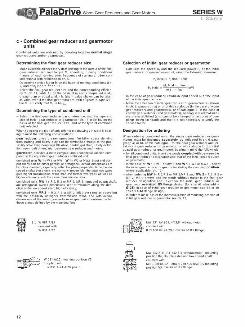
c - Combined gear reducer and gearmotorunits
C ombined units are obtained by c oupling together normal singlegear reduc ers and/or gearmotors .
Determining the final gear reducer size– Make available all nec essary data relating to the output of the final
gear reduc er: required torque M2 speed n2, running c onditions(nature of load, running time, frequenc y of s tarting z , other c on-s iderations) with referenc e to ch. 5.
– Determine servic e fac tor fs on the bas is of running c onditions (c h.5) and of n2 (see *, ** c h. 11).
– S elec t the final gear reduc er s ize and the c orresponding effic ien-c y (c h. 11, table A), on the bas is of n2 and a torque value MN2
greater than or equal to M2 · fs (the value shown c an be takenas valid even if the final gear reduc er’s train of gears is type IV).For fs 1 verify that M2 M2 S ize.
Determining the type of combined unit– S elec t the final gear reduc er bas ic referenc e, and the type and
size of initial gear reduc er or gearmotor (c h. 11 table B ), on thebas is of the final gear reducer s ize, and of the type of c ombinedunit selec ted.
When selec ting the type of unit, refer to the drawings in table B bear-ing in mind the following c onsiderations :
gear reducer: gives greater operational flexibility; s tress derivingfrom starting and heavy duty c an be diminished thanks to the pos-s ibility of loc ating c ouplings (flexibile, c entrifugal, fluid, safety or fric -tion type), belt drives , etc . between gear reduc er and motor.;
gearmotor: provides a more compact and economical solution com-pared to the equivalent gear reducer combined unit;
combined units W 1 + W 1 or MW1 W 1 + W2 or MW2 input and out-put shafts can be either parallel or orthogonal, overall dimensions arekept to a minimum, especially within the plane perpendicular to the lowspeed shafts ; these units are normally irrevers ible; the latter two typesgive higher transmiss ion ratios than the former two types as well ashigher effic iency, with the same transmiss ion ratio;
combined units MW 1 + R 2, R 3 or MR 2, MR 3 input and output shaftsare orthogonal, overall dimensions kept at minimum along the dire-ction of the low speed shaft; high effic iency;
combined units MR 2 + R 2, R 3 or MR 2, MR 3 the same as above butwith the possibility of higher transmiss ion ratios , and with overalldimensions of the initial gear reducer or gearmotor contained withinthose planes defined by the mounting feet.
E .g: W 081 A/25c oupled withW 031 A/32
W 081 A/25 mounting pos ition V5c oupled withMW 031 A-71 A/28 pos . 3
Selection of initial gear reducer or gearmotor– C alc ulate the speed n2 and the required power P2 at the initial
gear reduc er or gearmotor output, us ing the following formulae:
n2 initial = n2 final · i final
P2 initial = [kW]
– In the c ase of gear reduc er, establish input speed n1 at the inputof the initial gear reduc er.
– Make the selec tion of initial gear reduc er or gearmotors as shownin c h. 6, paragraph a) or b) of this c atalogue (in the c ase of wormgear reduc ers and gearmotors ), or of c atalogue E (in the c ase ofc oaxial gear reduc ers and gearmotors ), bearing in mind that s izesare pre-established (and c annot be c hanged on ac c ount of c ou-plings being standard) and that it is not nec essary to verify theservic e factor.
Designation for orderingWhen ordering c ombined units , the s ingle gear reduc ers or gear-motors must be des igned separately, as indic ated in c h. 6 para-graph a) or b), of this c atalogue (for the final gear reduc er and ini-tial worm gear reduc er or gearmotor) or of c atalogue E (for initialc oaxial gear reduc er or gearmotor), bearing in mind the following):– for all c ombined units , insert the words coupled with between the
final gear reduc er des ignation and that of the initial gear reduc eror gearmotor;
– in the c ase of W 1 + W 1 or MW 1 and W 1 + W2 or MW2 , selec tthe initial gear reduc er or gearmotor s tating the c oupling positionwhere applic able (c h. 12);
– when ordering MW 1 + R 2,R 3 or MR 2,MR 3 and MW 2 + R 2, R 3 orMR 2, MR 3 always add the words without motor to the final gearreduc er des ignation and selec t for the initial gear reduc er orgearmotor oversized B5 flange design (for s ize 63 also add –Ø 28); in c ase of initial gear reduc er or gearmotor s ize 32 or 40select FC1A flange des ign;
– in order to make easier the individualization of mounting position ofinitial gear reducer or gearmotor see ch. 12.
M2 final · n2 final
955 · final
MW 131 A-180 L 4/43,8 without motorc oupled withR 2I 100 UC 2A/29,3 overs ized B 5 flange
MW 132 A-1:17.1-132 B 5 without motor , mountingposition B 6, double extens ion low speed shaftc oupled withMR 3I 80 UC 2A - 80A 4 230.400 B 5/18,5 mounting
overs ized B 5 flangeposition V5
Worm Gear Reducers and Gear Motors SERIES WPalaDrive

13
6. Selection
Considerations on selectionMotor powerTaking into account the efficiency of the gear reducer, and otherdrives – if any – motor power is to be as near as possible to thepower rating required by the driven machine: accurate calculation istherefore recommended.The power required by the machine can be calculated, seeing thatit is related directly to several requirements of the work to be carriedout, to friction (starting, sliding or rolling friction) and inertia (partic-ularly when mass and/or acceleration or deceleration are consider-able). It can also be determined experimentally on the basis of tests,comparison with existing applications, or readings taken withamperometers or wattmeters.An oversized motor would involve: a greater starting current andconsequently larger fuses and heavier cable; a higher running costas power factor (cos ) and efficiency would suffer; greater stresson the drive, causing danger of mechanical failure, drive being nor-mally proportionate to the power rating required by the machine, notto motor power.Only high values of ambient temperature, altitude, frequency ofstarting or other particular conditions require an increase in motorpower.
Driving machines with high kinetic energyWhen driving machines with high inertias and/or speeds, avoid theuse of irreversible gear reducers or gearmotors, rather select a trainof gears with higher efficiency (e.g. IV, 2IV in place of V), keeping thesame transmission ratio, as stopping and braking can cause veryhigh overloads (cap. 15).
Drives with low input speed (n1 < 355 min-1)Wherever possible select the following transmission i = 20 for sizes 32... 50, i = 25 for sizes 63 ... 100, i = 32 for sizes 125 ... 200, i = 40 forsize 250, these being the ratios capable of transmitting highest torque(for performance figures see table A ch. 11; for sizes 32 and 40, con-sult us).
Input speedFor n1 higher than 1 400 min-1, power and torqueratings relating to a given transmission ratio varyas shown in the table alongside. In this case noloads should be imposed on the high speed shaftend.For variable n1, the selection should be carried outon the basis of n1 max; but it should also be verifiedon the basis of n1 min.When there is a belt drive between motor and gearreducer, different input speeds n1, should be exam-ined in order to select the most suitable unit fromengineering and economy standpoints alike (ourcatalogue favours this method of selection as itshows a number of input speed values n1 relatingto a determined output speed nN2 in the same sec-tion).Input speed should not be higher than 1 400 min-1,unless conditions make it necessary; better to takeadvantage of the transmission, and use an inputspeed lower than 900 min-1.
n1 PN2 MN2
min-1
2 800 1,4 0,712 240 1,25 0,81 800 1,12 0,91 400 1 1
Worm Gear Reducers and Gear Motors SERIES WPalaDrive

14
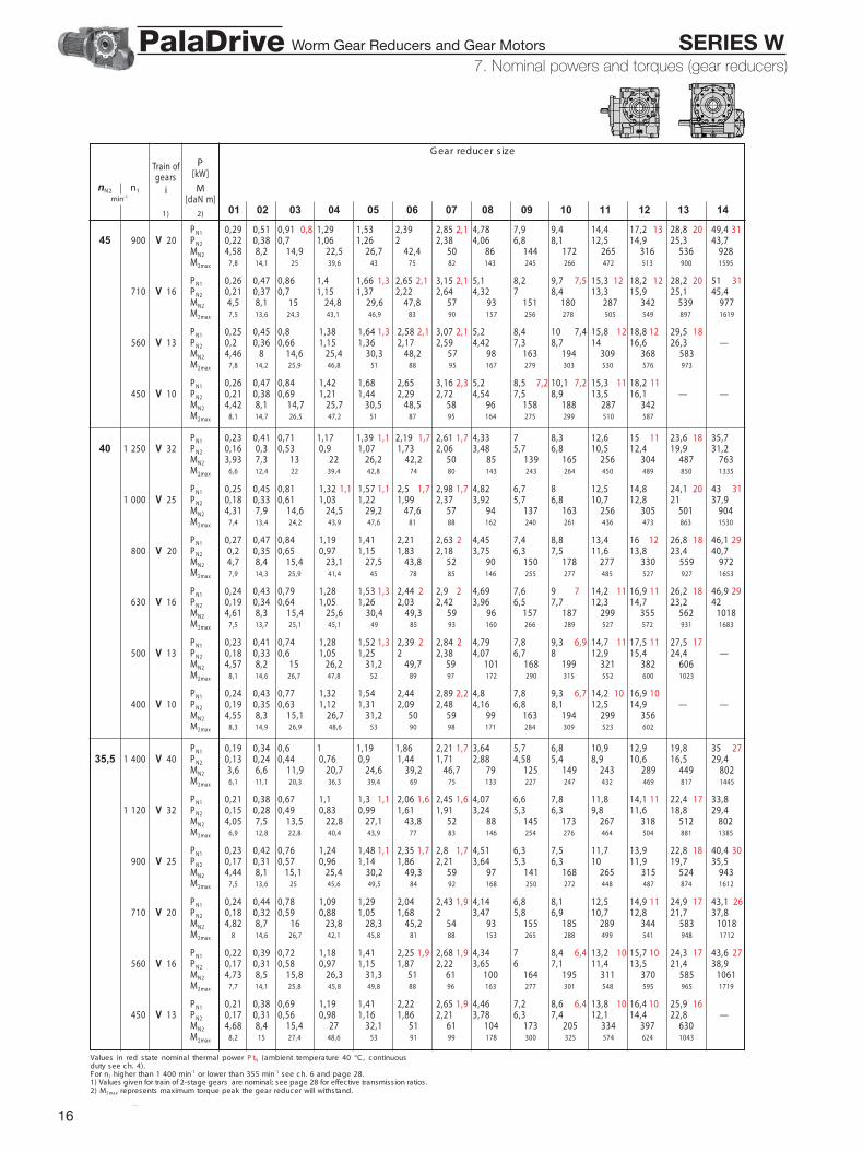
Values in red state nominal thermal power P tN (ambient temperature 40 °C , c ontinuousduty see c h. 4).For n1 higher than 1 400 min-1 or lower than 355 min-1 see ch. 6 and page 28.1) Values given for train of 2-stage gears are nominal; see page 28 for effective transmission ratios .2) M2max represents maximum torque peak the gear reduc er will withstand.
7 - Nominal powers and torques (gear reducers)
G ear reduc er s ize
01 02 03 04 05 06 07 08 09 10 11 12 13 14
nN2 n1min-1
Train ofgears
i
1)
P[kW]
M[daN m]
2)
PN1 0,57 1,01 1,79 1,4 3,02 2,3 3,59 2,3 5,5 3,6 6,6 3,6 10,6 16,7 19,8 15 29,9 23 35,6 23140 1 400 V 10 PN2 0,48 0,87 1,55 2,68 3,19 4,96 5,9 9,5 15,1 18 27,3 32,5 — —
MN2 3,29 5,9 10,6 18,3 21,7 33,9 40,3 65 103 123 186 222M2max 5,9 10,5 19,4 33,2 36,1 63 68 120 188 204 342 394
PN1 0,53 0,94 1,66 1,3 2,82 2,2 3,36 2,2 5,2 3,4 6,2 3,4 9,9 15,7 18,7 14 28,1 22 33,5 22125 1 250 V 10 PN2 0,44 0,82 1,44 2,5 2,97 4,65 5,5 8,9 14,2 16,9 25,6 30,5 — —
MN2 3,4 6,1 11 19,1 22,7 35,6 42,3 68 109 129 196 233M2max 6,2 11,2 19,9 35,1 38,1 65 70 124 195 212 357 410
PN1 0,47 0,82 1,49 2,44 2,1 2,9 2,1 4,55 3,1 5,4 3,1 9 14,4 17,2 14 26,6 22 31,6 22 47,9 33112 1 400 V 13 PN2 0,39 0,69 1,27 2,12 2,52 3,99 4,75 8 13 15,4 24 28,6 43,6 —
MN2 3,47 6,1 11,3 18,8 22,3 35,4 42,1 71 115 137 213 254 386M2max 6,2 11,3 20,6 35,1 38,1 66 71 128 203 220 380 413 716
PN1 0,49 0,88 1,55 1,3 2,64 2,1 3,14 2,1 4,91 3,3 5,8 3,3 9,3 14,9 17,7 13 26,5 20 31,5 201 120 V 10 PN2 0,41 0,75 1,34 2,33 2,77 4,37 5,2 8,4 13,4 16 24 28,6 — —
MN2 3,51 6,4 11,4 19,9 23,6 37,3 44,3 71 115 136 205 244M2max 6,4 11,5 20,5 37 40,2 67 73 128 203 220 371 427
PN1 0,43 0,76 1,39 2,28 1,9 2,72 1,9 4,25 2,9 5,1 2,9 8,5 13,6 16,1 13 25 20 29,8 20 45,4 31100 1 250 V 13 PN2 0,36 0,64 1,18 1,97 2,35 3,71 4,41 7,5 12,1 14,4 22,6 26,9 41,2 —
MN2 3,58 6,4 11,8 19,6 23,3 36,8 43,8 74 121 143 225 267 409M2max 6,4 11,6 21,1 36,9 40,1 69 75 135 219 238 412 448 748
PN1 0,45 0,82 1,44 1,2 2,46 2,1 2,92 2,1 4,57 3,1 5,4 3,1 8,7 14 16,7 12 24,7 19 29,4 191 000 V 10 PN2 0,38 0,69 1,23 2,16 2,57 4,05 4,82 7,8 12,6 15 22,4 26,7 — —
MN2 3,62 6,6 11,8 20,6 24,5 38,7 46,1 74 120 143 214 255M2max 6,6 11,8 21 38,2 41,5 70 77 134 214 233 393 452
PN1 0,41 0,73 1,3 2,14 1,8 2,55 1,8 4,03 2,8 4,79 2,8 7,5 12 14,3 12 22,5 19 26,8 19 41,3 31 74 4990 1 400 V 16 PN2 0,34 0,61 1,1 1,83 2,18 3,49 4,15 6,6 10,6 12,6 20,1 23,9 37,3 67
MN2 3,67 6,6 12 20 23,8 38,1 45,3 72 116 138 219 261 407 732M2max 6,1 11,1 20,2 35,9 39 68 73 127 206 224 403 437 705 1273
PN1 0,41 0,71 1,3 2,14 1,8 2,55 1,8 3,97 2,8 4,73 2,8 8 12,8 15,2 12 23,6 19 28,1 19 43,1 291 120 V 13 PN2 0,33 0,61 1,1 1,84 2,19 3,45 4,11 7 11,4 13,5 21,3 25,3 39 —
MN2 3,7 6,6 12,2 20,4 24,3 38,3 45,5 78 126 150 236 281 433M2max 6,6 11,9 21,7 38,5 41,8 72 79 141 227 246 427 464 781
PN1 0,42 0,77 1,35 2,3 1,9 2,74 1,9 4,28 3,1 5,1 3,1 8,2 13,2 15,8 11 23,3 17 27,7 17900 V 10 PN2 0,35 0,65 1,15 2,01 2,39 3,78 4,5 7,3 11,9 14,2 21 25 — —
MN2 3,73 6,9 12,2 21,3 25,4 40,1 47,7 78 126 150 223 265M2max 6,7 12,1 21,5 39,4 42,7 74 80 140 225 245 407 468
PN1 0,38 0,68 1,22 2 2,38 1,7 3,78 2,7 4,5 2,7 7,1 11,3 13,4 11 21,2 17 25,2 17 38,8 29 69 4580 1 250 V 16 PN2 0,31 0,56 1,02 1,7 2,03 3,26 3,88 6,2 9,9 11,8 18,8 22,4 35 63
MN2 3,81 6,9 12,5 20,8 24,8 39,8 47,4 75 121 144 230 274 428 770M2max 6,4 11,5 20,7 37 40,2 70 76 136 213 232 418 454 736 1329
PN1 0,37 0,66 1,21 2 1,7 2,38 1,7 3,71 2,6 4,42 2,6 7,4 12 14,3 11 22,1 17 26,4 17 40,7 271 000 V 13 PN2 0,31 0,55 1,02 1,71 2,03 3,21 3,82 6,5 10,7 12,7 19,9 23,7 36,7 —
MN2 3,82 6,8 12,6 21,2 25,2 39,9 47,4 81 133 158 247 294 456M2max 6,8 12,3 22,2 39,6 43 74 80 145 234 254 442 481 814
PN1 0,39 0,71 1,25 2,12 2,52 1,8 3,96 2,8 4,71 2,8 7,6 12,4 10 14,7 10 21,7 16 25,8 16800 V 10 PN2 0,32 0,59 1,06 1,85 2,2 3,48 4,14 6,8 11,1 13,2 19,5 23,3 — —
MN2 3,85 7,1 12,6 22 26,2 41,5 49,4 81 132 157 233 278M2max 7,1 12,7 22,8 40,4 43,9 76 83 143 233 253 429 493
PN1 0,38 0,67 1,18 0,9 1,7 2,03 1,7 3,14 2,6 3,73 2,6 6,2 10,1 12,1 18,6 22,1 17 36,2 27 62 4171 1 400 V 20 PN2 0,29 0,52 0,94 1,44 1,71 2,68 3,19 5,3 8,9 10,6 16,4 19,5 32,2 56
MN2 4,01 7,1 12,8 19,6 23,3 36,6 43,5 73 121 144 224 266 439 759M2max 6,8 12,2 22,3 34,6 37,5 65 71 126 209 227 401 436 744 1308
PN1 0,36 0,64 1,15 1,87 2,23 1,6 3,55 2,5 4,23 2,5 6,6 10,6 12,6 10 20 16 23,8 16 36,6 27 65 421 120 V 16 PN2 0,29 0,52 0,96 1,59 1,89 3,05 3,63 5,8 9,3 11,1 17,7 21,1 33 59
MN2 3,95 7,1 13,1 21,6 25,7 41,6 49,5 79 127 151 242 288 450 808M2max 6,6 12 21,2 38,1 41,4 72 78 139 220 239 432 470 767 1384
PN1 0,35 0,62 1,13 1,87 2,23 1,6 3,49 2,5 4,15 2,5 7 11,4 13,5 10 20,8 16 24,8 16 38,6 25900 V 13 PN2 0,29 0,51 0,94 1,59 1,89 3 3,57 6,1 10,1 12 18,7 22,2 34,7 —
MN2 3,93 7 13 22 26,1 41,4 49,3 84 139 165 257 306 479M2max 6,9 12,5 22,7 39,7 43,2 75 81 149 242 263 457 497 847
PN1 0,36 0,65 1,16 1,95 2,33 1,8 3,65 2,7 4,35 2,7 7,1 11,5 9,6 13,7 9,6 20,2 15 24 15710 V 10 PN2 0,3 0,54 0,97 1,69 2,01 3,2 3,81 6,3 10,3 12,2 18,2 21,6 — —
MN2 3,98 7,3 13,1 22,8 27,1 43 51 84 138 165 244 291M2max 7,2 13 23,3 41,3 44,9 78 85 147 240 260 442 509
7. Nominal powers and torques (gear reducers)
7. Nominal powers and torques (gear reducers)Worm Gear Reducers and Gear Motors SERIES WPalaDrive

15
Values in red state nominal thermal power P tN (ambient temperature 40 °C , c ontinuousduty see c h. 4).For n1 higher than 1 400 min-1 or lower than 355 min-1 see ch. 6 and page 28.1) Values given for train of 2-stage gears are nominal; see page 28 for effective transmission ratios .2) M2max represents maximum torque peak the gear reduc er will withstand.
7 - Nominal powers and torques (gear reduc ers )
G ear reduc er s ize
01 02 03 04 05 06 07 08 09 10 11 12 13 14
nN2 n1min-1
Train ofgears
i
1)
P[kW]
M[daN m]
2)
PN1 0,35 0,63 1,1 0,9 1,59 1,89 1,6 2,93 2,4 3,49 2,4 5,8 9,6 11,4 17,4 20,8 16 34,2 25 59 3863 1 250 V 20 PN2 0,27 0,49 0,87 1,33 1,58 2,49 2,96 4,98 8,3 9,9 15,3 18,2 30,3 52
MN2 4,15 7,4 13,4 20,3 24,2 38 45,3 76 127 151 234 279 463 798M2max 6,9 12,7 22,8 36,7 39,9 69 75 129 224 243 415 451 790 1366
PN1 0,33 0,59 1,07 1,75 2,08 1,6 3,31 2,4 3,93 2,4 6,2 10 11,8 9,6 18,7 15 22,3 15 34,5 25 61 391 000 V 16 PN2 0,27 0,48 0,89 1,47 1,75 2,82 3,36 5,4 28,7 10,3 16,5 19,7 30,9 56
MN2 4,08 7,3 13,6 22,4 26,7 43,2 51 82 133 158 253 301 473 849M2max 6,8 12,2 22,3 39,2 42,6 74 80 145 228 247 463 503 843 1441
PN1 0,32 0,57 1,04 1,74 2,07 1,5 3,24 2,4 3,86 2,4 6,5 10,6 12,6 9,4 19,5 15 23,2 15 36,1 23800 V 13 PN2 0,26 0,47 0,86 1,47 1,75 2,78 3,3 5,6 29,3 11,1 17,4 20,7 32,4 —
MN2 4,07 7,3 13,4 22,8 27,1 43,1 51 87 145 172 270 321 503M2max 7,2 12,9 23,9 42 45,6 79 86 152 257 280 477 518 907
PN1 0,33 0,6 1,06 1,8 2,14 1,7 3,37 2,6 4,01 2,6 6,5 10,7 9,1 12,7 9,1 18,8 14 22,3 14630 V 10 PN2 0,27 0,5 0,89 1,55 1,85 2,94 3,5 5,8 29,5 11,3 16,8 20 — —
MN2 4,09 7,5 13,5 23,5 28 44,5 53 87 144 171 255 303M2max 7,5 13,6 23,7 43,5 47,2 80 87 150 247 268 463 533
PN1 0,36 0,55 0,99 1,61 1,3 1,92 1,3 3,04 2,1 3,61 2,1 5,9 8,4 9,9 15,3 18,2 28,4 51 3956 1 400 V 25 PN2 0,23 0,42 0,77 1,29 1,53 2,47 2,94 4,89 7,2 8,6 13,3 15,9 25 45,7
MN2 3,89 7,2 13,2 21,9 26,1 42,2 50 83 123 146 227 270 426 779M2max 6,6 12,3 22,4 38,5 41,9 73 80 148 217 235 397 432 745 1341
PN1 0,33 0,59 1,04 0,8 1,48 1,76 2,74 3,26 2,3 5,4 9 10,7 16,4 19,5 15 32,4 23 55 361 120 V 20 PN2 0,25 0,45 0,81 1,23 1,47 2,32 2,76 4,65 7,8 9,3 14,3 17,1 28,6 49,2
MN2 4,28 7,7 13,9 21 25 39,5 47 79 133 158 245 291 488 838M2max 7,1 13,2 23,3 37,8 41 71 77 132 231 251 429 466 836 1424
PN1 0,31 0,55 1 1,64 1,95 1,5 3,1 2,3 3,68 2,3 5,8 9,4 11,2 8,9 17,6 14 21 14 32,6 23 58 37900 V 16 PN2 0,25 0,45 0,83 1,37 1,63 2,63 3,13 5 8,2 9,7 15,5 18,4 29,2 52
MN2 4,21 7,6 14 23,2 27,6 44,6 53 85 139 165 263 313 495 889M2max 7,1 12,8 22,8 40,3 43,8 76 83 146 235 255 477 518 855 1498
PN1 0,3 0,53 0,95 1,61 1,92 1,5 3,01 2,3 3,58 2,3 6 9,8 11,7 8,7 18,2 14 21,7 14 33,7 21710 V 13 PN2 0,24 0,43 0,79 1,36 1,61 2,56 3,05 5,2 8,6 10,3 16,2 19,3 30,2 —
MN2 4,22 7,5 13,8 23,7 28,2 44,8 53 91 151 180 283 337 528M2max 7,3 13,3 24,3 42,9 46,6 82 89 156 265 287 494 528 929
PN1 0,3 0,55 0,98 1,66 1,97 1,6 3,11 2,5 3,7 2,5 6 9,9 8,3 11,8 8,3 17,5 13 20,8 13560 V 10 PN2 0,25 0,45 0,82 1,43 1,7 2,7 3,21 5,3 8,8 10,4 15,6 18,6 — —
MN2 4,21 7,7 13,9 24,3 29 46 55 90 149 178 266 316M2max 7,7 13,9 24,9 44,3 48,2 82 89 153 253 275 476 548
PN1 0,28 0,52 0,92 1,51 1,2 1,79 1,2 2,85 1,9 3,39 1,9 5,5 7,8 9,3 14,2 17 26,9 48,4 3750 1 250 V 25 PN2 0,21 0,39 0,71 1,19 1,42 2,3 2,74 4,55 6,7 8 12,4 14,8 23,7 43
MN2 4,03 7,5 13,6 22,8 27,1 44 52 87 128 152 237 282 452 821M2max 6,9 12,5 22,9 40,9 44,5 76 82 153 223 243 410 446 783 1395
PN1 0,31 0,54 0,97 0,8 1,38 1,64 2,55 3,04 2,2 5,1 8,4 10 15,3 18,3 14 30,5 21 52 331 000 V 20 PN2 0,23 0,42 0,75 1,14 1,36 2,15 2,55 4,33 7,3 8,6 13,4 15,9 26,8 46,3
MN2 4,43 7,9 14,4 21,8 25,9 41 48,8 83 139 165 255 304 512 884M2max 7,4 13,6 24,5 38,8 42,1 73 80 140 238 258 458 498 869 1509
PN1 0,29 0,51 0,93 1,51 1,8 1,4 2,86 2,2 3,41 2,2 5,4 8,8 10,4 8,2 16,4 13 19,6 13 30,3 21 54 34800 V 16 PN2 0,23 0,41 0,76 1,26 1,5 2,42 2,88 4,66 7,6 9 14,4 17,1 27,1 48,8
MN2 4,35 7,8 14,5 24 28,6 46,2 55 89 145 172 275 327 517 932M2max 7,3 13,2 23 42,3 46 81 88 152 245 266 491 534 876 1608
PN1 0,27 0,49 0,87 1,49 1,78 1,4 2,78 2,2 3,31 2,2 5,6 9,1 10,8 8 17 13 20,2 13 31,5 20630 V 13 PN2 0,22 0,39 0,72 1,25 1,48 2,36 2,81 4,79 8 9,5 15 17,9 28,2 —
MN2 4,34 7,8 14,2 24,6 29,2 46,5 55 94 157 187 296 352 555M2max 7,6 13,9 25,2 45 48,9 85 92 161 272 295 513 575 951
PN1 0,28 0,5 0,9 1,53 1,82 1,5 2,86 2,3 3,41 2,3 5,6 9,1 7,7 10,9 7,7 16,3 12 19,4 12500 V 10 PN2 0,23 0,41 0,75 1,31 1,56 2,48 2,95 4,88 8,1 9,6 14,5 17,2 — —
MN2 4,31 7,9 14,3 25 29,7 47,3 56 93 154 183 276 329M2max 7,9 14,5 25,7 46,4 50 85 92 161 265 287 490 563
PN1 0,24 0,44 0,75 1,26 1,5 1,2 2,35 1,8 2,79 1,8 4,63 7,4 8,8 13,4 16 13 25 19 37,845 1 400 V 32 PN2 0,17 0,33 0,57 0,98 1,16 1,86 2,22 3,74 6,1 7,2 11,2 13,3 21,2 33,2
MN2 3,81 7,1 12,4 21,3 25,4 40,7 48,4 82 133 158 245 291 462 724M2max 6,4 12 21,3 37,2 40,4 70 77 140 236 256 436 473 817 1287
PN1 0,26 0,48 0,86 1,41 1,2 1,68 1,2 2,68 1,8 3,19 1,8 5,2 7,3 8,6 13,4 15,9 25,6 22 45,8 341 120 V 25 PN2 0,2 0,36 0,66 1,11 1,32 2,15 2,56 4,24 6,2 7,4 11,6 13,8 22,4 40,5
MN2 4,17 7,7 14,1 23,7 28,2 45,8 54 90 132 157 247 294 478 863M2max 7,1 12,8 23,4 42,1 45,7 78 84 156 230 250 423 460 819 1449
7. Nominal powers and torques (gear reducers)Worm Gear Reducers and Gear Motors SERIES WPalaDrive
16
7. Nominal powers and torques (gear reducers)
Values in red state nominal thermal power P tN (ambient temperature 40 °C , c ontinuousduty see c h. 4).For n1 higher than 1 400 min-1 or lower than 355 min-1 see c h. 6 and page 28.1) Values given for train of 2-stage gears are nominal; see page 28 for effective transmission ratios .2) M2max represents maximum torque peak the gear reduc er will withstand.
7 - Nominal powers and torques (gear reduc ers )
G ear reduc er s ize
01 02 03 04 05 06 07 08 09 10 11 12 13 14
nN2 n1min-1
Train ofgears
i
1)
P[kW]
M[daN m]
2)
PN1 0,29 0,51 0,91 0,8 1,29 1,53 2,39 2,85 2,1 4,78 7,9 9,4 14,4 17,2 13 28,8 20 49,4 3145 900 V 20 PN2 0,22 0,38 0,7 1,06 1,26 2 2,38 4,06 6,8 8,1 12,5 14,9 25,3 43,7
MN2 4,58 8,2 14,9 22,5 26,7 42,4 50 86 144 172 265 316 536 928M2max 7,8 14,1 25 39,6 43 75 82 143 245 266 472 513 900 1595
PN1 0,26 0,47 0,86 1,4 1,66 1,3 2,65 2,1 3,15 2,1 5,1 8,2 9,7 7,5 15,3 12 18,2 12 28,2 20 51 31710 V 16 PN2 0,21 0,37 0,7 1,15 1,37 2,22 2,64 4,32 7 8,4 13,3 15,9 25,1 45,4
MN2 4,5 8,1 15 24,8 29,6 47,8 57 93 151 180 287 342 539 977M2max 7,5 13,6 24,3 43,1 46,9 83 90 157 256 278 505 549 897 1619
PN1 0,25 0,45 0,8 1,38 1,64 1,3 2,58 2,1 3,07 2,1 5,2 8,4 10 7,4 15,8 12 18,8 12 29,5 18560 V 13 PN2 0,22 0,36 0,66 1,15 1,36 2,17 2,59 4,42 7,3 8,7 14 16,6 26,3 —
MN2 4,46 8 14,6 25,4 30,3 48,2 57 98 163 194 309 368 583M2max 7,8 14,2 25,9 46,8 51 88 95 167 279 303 530 576 973
PN1 0,26 0,47 0,84 1,42 1,68 2,65 3,16 2,3 5,2 8,5 7,2 10,1 7,2 15,3 11 18,2 11450 V 10 PN2 0,21 0,38 0,69 1,21 1,44 2,29 2,72 4,54 7,5 8,9 13,5 16,1 — —
MN2 4,42 8,1 14,7 25,7 30,5 48,5 58 96 158 188 287 342M2max 8,1 14,7 26,5 47,2 51 87 95 164 275 299 510 587
PN1 0,23 0,41 0,71 1,17 1,39 1,1 2,19 1,7 2,61 1,7 4,33 7 8,3 12,6 15 11,1 23,6 18 35,740 1 250 V 32 PN2 0,16 0,3 0,53 0,9 1,07 1,73 2,06 3,48 5,7 6,8 10,5 12,4 19,9 31,2
MN2 3,93 7,3 13 22 26,2 42,2 50 85 139 165 256 304 487 763M2max 6,6 12,4 22 39,4 42,8 74 80 143 243 264 450 489 850 1335
PN1 0,25 0,45 0,81 1,32 1,1 1,57 1,1 2,5 1,7 2,98 1,7 4,82 6,7 8 12,5 14,8 24,1 20 43 311 000 V 25 PN2 0,18 0,33 0,61 1,03 1,22 1,99 2,37 3,92 5,7 6,8 10,7 12,8 21 37,9
MN2 4,31 7,9 14,6 24,5 29,2 47,6 57 94 137 163 256 305 501 904M2max 7,4 13,4 24,2 43,9 47,6 81 88 162 240 261 436 473 863 1530
PN1 0,27 0,47 0,84 1,19 1,41 2,21 2,63 2 4,45 7,4 8,8 13,4 16 12 26,8 18 46,1 29800 V 20 PN2 0,2 0,35 0,65 0,97 1,15 1,83 2,18 3,75 6,3 7,5 11,6 13,8 23,4 40,7
MN2 4,7 8,4 15,4 23,1 27,5 43,8 52 90 150 178 277 330 559 972M2max 7,9 14,3 25,9 41,4 45 78 85 146 255 277 485 527 927 1653
PN1 0,24 0,43 0,79 1,28 1,53 1,3 2,44 2 2,9 2 4,69 7,6 9 7 14,2 11 16,9 11 26,2 18 46,9 29630 V 16 PN2 0,19 0,34 0,64 1,05 1,26 2,03 2,42 3,96 6,5 7,7 12,3 14,7 23,2 42
MN2 4,61 8,3 15,4 25,6 30,4 49,3 59 96 157 187 299 355 562 1018M2max 7,5 13,7 25,1 45,1 49 85 93 160 266 289 527 572 931 1683
PN1 0,23 0,41 0,74 1,28 1,52 1,3 2,39 2 2,84 2 4,79 7,8 9,3 6,9 14,7 11 17,5 11 27,5 17500 V 13 PN2 0,18 0,33 0,6 1,05 1,25 2 2,38 4,07 6,7 8 12,9 15,4 24,4 —
MN2 4,57 8,2 15 26,2 31,2 49,7 59 101 168 199 321 382 606M2max 8,1 14,6 26,7 47,8 52 89 97 172 290 315 552 600 1023
PN1 0,24 0,43 0,77 1,32 1,54 2,44 2,89 2,2 4,8 7,8 9,3 6,7 14,2 10 16,9 10400 V 10 PN2 0,19 0,35 0,63 1,12 1,31 2,09 2,48 4,16 6,8 8,1 12,5 14,9 — —
MN2 4,55 8,3 15,1 26,7 31,2 50 59 99 163 194 299 356M2max 8,3 14,9 26,9 48,6 53 90 98 171 284 309 523 602
PN1 0,19 0,34 0,6 1 1,19 1,86 2,21 1,7 3,64 5,7 6,8 10,9 12,9 19,8 35 2735,5 1 400 V 40 PN2 0,13 0,24 0,44 0,76 0,9 1,44 1,71 2,88 4,58 5,4 8,9 10,6 16,5 29,4
MN2 3,6 6,6 11,9 20,7 24,6 39,2 46,7 79 125 149 243 289 449 802M2max 6,1 11,1 20,3 36,3 39,4 69 75 133 227 247 432 469 817 1445
PN1 0,21 0,38 0,67 1,1 1,3 1,1 2,06 1,6 2,45 1,6 4,07 6,6 7,8 11,8 14,1 11 22,4 17 33,81 120 V 32 PN2 0,15 0,28 0,49 0,83 0,99 1,61 1,91 3,24 5,3 6,3 9,8 11,6 18,8 29,4
MN2 4,05 7,5 13,5 22,8 27,1 43,8 52 88 145 173 267 318 512 802M2max 6,9 12,8 22,8 40,4 43,9 77 83 146 254 276 464 504 881 1385
PN1 0,23 0,42 0,76 1,24 1,48 1,1 2,35 1,7 2,8 1,7 4,51 6,3 7,5 11,7 13,9 22,8 18 40,4 30900 V 25 PN2 0,17 0,31 0,57 0,96 1,14 1,86 2,21 3,64 5,3 6,3 10 11,9 19,7 35,5
MN2 4,44 8,1 15,1 25,4 30,2 49,3 59 97 141 168 265 315 524 943M2max 7,5 13,6 25 45,6 49,5 84 92 168 250 272 448 487 874 1612
PN1 0,24 0,44 0,78 1,09 1,29 2,04 2,43 1,9 4,14 6,8 8,1 12,5 14,9 11 24,9 17 43,1 26710 V 20 PN2 0,18 0,32 0,59 0,88 1,05 1,68 2 3,47 5,8 6,9 10,7 12,8 21,7 37,8
MN2 4,82 8,7 16 23,8 28,3 45,2 54 93 155 185 289 344 583 1018M2max 8 14,6 26,7 42,1 45,8 81 88 153 265 288 499 541 948 1712
PN1 0,22 0,39 0,72 1,18 1,41 2,25 1,9 2,68 1,9 4,34 7 8,4 6,4 13,2 10 15,7 10 24,3 17 43,6 27560 V 16 PN2 0,17 0,31 0,58 0,97 1,15 1,87 2,22 3,65 6 7,1 11,4 13,5 21,4 38,9
MN2 4,73 8,5 15,8 26,3 31,3 51 61 100 164 195 311 370 585 1061M2max 7,7 14,1 25,8 45,8 49,8 88 96 163 277 301 548 595 965 1719
PN1 0,21 0,38 0,69 1,19 1,41 2,22 2,65 1,9 4,46 7,2 8,6 6,4 13,8 10 16,4 10,1 25,9 16450 V 13 PN2 0,17 0,31 0,56 0,98 1,16 1,86 2,21 3,78 6,3 7,4 12,1 14,4 22,8 —
MN2 4,68 8,4 15,4 27 32,1 51 61 104 173 205 334 397 630M2max 8,2 15 27,4 48,6 53 91 99 178 300 325 574 624 1043
Worm Gear Reducers and Gear Motors SERIES WPalaDrive

17
7. Nominal powers and torques (gear reducers)
Values in red state nominal thermal power P tN (ambient temperature 40 °C , c ontinuousduty see c h. 4).For n1 higher than 1 400 min-1 or lower than 355 min-1 s ee c h. 6 and page 28.1) Values given for train of 2-stage gears are nominal; see page 28 for effective transmission ratios .2) M2max represents maximum torque peak the gear reduc er will withstand.
7 - Nominal powers and torques (gear reduc ers )
G ear reduc er s ize
01 02 03 04 05 06 07 08 09 10 11 12 13 14
nN2 n1min-1
Train ofgears
i
1)
P[kW]
M[daN m]
2)
PN1 0,22 0,39 0,71 1,22 1,4 2,24 2,65 2,1 4,41 7,2 8,5 6,2 13,1 9,6 15,6 9,635,5 355 V 10 PN2 0,17 0,31 0,58 1,03 1,19 1,91 2,26 3,81 6,2 7,4 11,5 13,7 — —
MN2 4,69 8,4 15,6 27,7 31,9 51 61 102 168 200 311 370M2max 8,4 15,1 27,3 49,9 54 93 101 174 293 318 542 623
PN1 0,18 0,32 0,56 0,94 1,11 1,74 2,07 1,6 3,39 5,4 6,4 10,2 12,1 18,7 32,8 2531,5 1 250 V 40 PN2 0,12 0,22 0,4 0,7 0,83 1,33 1,59 2,67 4,26 5,1 8,3 9,9 15,4 27,5
MN2 3,71 6,8 12,3 21,4 25,5 40,7 48,5 82 130 155 253 302 471 840M2max 6,4 11,6 21 38,3 41,6 71 77 136 234 254 445 484 846 1501
PN1 0,2 0,35 0,62 1,02 1,22 1 1,91 1,6 2,28 1,6 3,79 6,1 7,3 11,1 13,2 9,8 21 15 31,61 000 V 32 PN2 0,14 0,25 0,45 0,77 0,92 1,48 1,76 2,99 4,95 5,9 9,1 10,8 17,6 27,4
MN2 4,19 7,7 13,9 23,6 28 45,3 54 91 151 180 277 330 536 838M2max 7,1 12,9 23,2 42 45,6 79 85 152 261 283 493 536 929 1458
PN1 0,21 0,38 0,7 1,15 1,37 1 2,17 1,6 2,59 1,6 4,17 5,8 6,9 10,7 12,8 21,2 17 37,9 27800 V 25 PN2 0,15 0,28 0,52 0,88 1,04 1,7 2,02 3,34 4,88 5,8 19,2 10,9 18,3 33,1
MN2 4,58 8,3 15,4 26,2 31,2 51 60 100 146 173 273 325 546 988M2max 7,8 14,2 25,8 46,6 51 86 94 169 257 279 467 508 908 1668
PN1 0,22 0,41 0,72 0,99 1,18 1,87 2,23 1,8 3,83 6,3 7,5 6,3 11,6 13,8 10 23,1 16 40,3 24630 V 20 PN2 0,16 0,31 0,54 0,8 0,95 1,53 1,83 3,19 5,3 6,3 09,9 11,8 20 35,3
MN2 4,96 9 16,5 24,3 28,9 46,5 55 97 161 192 300 357 606 1069M2max 8,3 15 27,5 43,9 47,7 83 90 156 272 295 519 564 983 1778
PN1 0,21 0,36 0,66 1,09 1,29 2,07 2,46 1,8 4,01 6,5 7,8 6 12,3 9,4 14,6 9,4 22,4 16 40,3 25500 V 16 PN2 0,16 0,28 0,53 0,88 1,05 1,71 2,03 3,35 5,5 6,6 10,5 12,5 19,7 35,7
MN2 4,84 8,7 16,2 26,9 32,1 52 62 102 169 201 322 383 601 1092M2max 7,9 14,3 26,5 47,2 51 91 99 171 284 308 561 610 984 1754
PN1 0,21 0,35 0,63 1,09 1,3 2,05 2,44 1,8 4,12 6,6 7,9 6 12,8 9,5 15,2 9,5 23,9 15400 V 13 PN2 0,15 0,28 0,51 0,89 1,06 1,7 2,03 3,47 5,7 6,8 11,1 13,3 21 —
MN2 4,78 8,6 15,7 27,8 33 53 63 108 177 211 346 411 653M2max 8,4 15 27,8 49,9 54 95 103 181 309 335 588 638 1063
PN1 0,21 0,34 0,63 1 1,2 1,91 2,28 1,7 3,72 6,2 7,4 5,6 11,5 8,7 13,7 8,7 20,8 15 37,4 2328 1 400 IV 50 PN2 0,14 0,26 0,49 0,79 0,94 1,54 1,83 3,03 5,1 6,1 09,6 11,5 17,8 32,5
MN2 5,1 8,9 16,6 27,6 32,8 53 64 105 174 208 334 397 618 1125M2max 8,5 14,5 27,2 48,4 53 93 101 173 289 314 575 624 1002 1788
PN1 0,14 0,26 0,47 0,77 0,92 1,44 1,72 2,69 4,49 5,3 08,3 09,9 16 28,11 400 V 50 PN2 0,11 0,18 0,32 0,56 0,67 1,08 1,29 2,07 3,52 4,19 06,7 07,9 13 23,3
MN2 3,24 6 11,1 19,2 22,9 36,9 43,9 71 120 143 227 270 445 795M2max 5,2 10 19,6 34,7 37,7 65 71 123 212 231 409 445 786 1408
PN1 0,16 0,31 0,52 0,88 1,04 1,63 1,94 1,5 3,18 5,1 6 09,6 11,4 9,7 17,6 15 30,9 241 120 V 40 PN2 0,11 0,21 0,37 0,65 0,77 1,24 1,47 2,48 3,98 4,74 07,7 09,2 14,5 25,8
MN2 3,81 7 12,7 22,1 26,3 42,2 50 85 136 162 264 315 494 879M2max 6,5 11,8 21,7 39,2 42,6 72 79 139 241 261 458 498 876 1557
PN1 0,18 0,33 0,58 0,96 1,14 1 1,79 1,5 2,13 1,5 3,55 5,8 6,9 5,8 10,4 12,4 9,1 19,8 14 29,8900 V 32 PN2 0,13 0,23 0,42 0,72 0,85 1,37 1,64 2,78 4,63 5,5 08,5 10,1 16,5 25,7
MN2 4,32 7,9 14,3 24,3 29 46,7 56 94 157 187 287 342 560 874M2max 7,3 13,6 23,6 43,6 47,3 81 88 157 268 291 507 551 977 1530
PN1 0,20 0,35 0,64 1,06 1,27 1 2,01 1,5 2,39 1,5 3,85 5,4 6,4 09,9 11,7 19,7 16 35,4 25710 V 25 PN2 0,14 0,25 0,47 0,8 0,96 1,55 1,85 3,06 4,48 5,3 08,4 10 16,9 30,8
MN2 4,73 8,5 15,8 27 32,2 52 62 103 151 179 282 335 569 1036M2max 8 14,4 26,5 47,4 51 88 96 175 263 286 486 528 941 1704
PN1 0,21 0,37 0,67 0,91 1,08 1,72 2,05 3,54 5,8 6,9 5,8 10,7 12,8 9,2 21,4 15 37,7 23560 V 20 PN2 0,15 0,27 0,5 0,73 0,87 1,4 1,67 2,93 4,89 5,8 09,1 10,9 18,5 32,9
MN2 5,1 9,3 17,1 24,8 29,6 47,8 57 100 167 199 312 371 629 1121M2max 8,5 15,6 28,2 44,6 48,5 86 93 158 279 303 539 586 1017 1842
PN1 0,19 0,34 0,62 1,01 1,2 1,92 2,28 1,7 3,73 6,1 7,3 5,6 11,5 8,7 13,7 8,7 20,8 15 37,4 23450 V 16 PN2 0,15 0,26 0,49 0,81 0,97 1,57 1,87 3,1 5,1 6,1 09,8 11,7 18,2 33,1
MN2 4,96 8,9 16,6 27,6 32,8 53 64 105 174 208 334 397 618 1125M2max 8 14,5 27,2 48,4 53 93 101 173 289 314 575 624 1002 1788
PN1 0,18 0,32 0,58 1,01 1,2 1,89 2,25 1,7 3,79 6,1 7,2 5,6 11,8 8,8 14 8,8 22,1 14355 V 13 PN2 0,14 0,25 0,46 0,82 0,97 1,56 1,86 3,17 5,2 6,2 10,2 12,2 19,4 —
MN2 4,89 8,8 16,1 28,6 34 55 65 111 182 217 358 426 677M2max 8,5 15,7 28,2 51 56 96 104 183 317 345 597 649 1081
PN1 0,19 0,31 0,58 0,92 1,09 1,75 2,09 1,7 3,42 5,7 6,8 5,2 10,7 8,1 12,7 8,1 19,1 14 34,6 2225 1 250 IV 50 PN2 0,13 0,24 0,44 0,72 0,86 1,4 1,67 2,77 4,68 5,6 08,9 10,6 16,3 29,9
MN2 5,2 9,1 16,9 28,1 33,4 55 65 108 178 212 345 410 634 1161M2max 8,7 14,9 27,6 49,1 53 95 103 178 298 323 588 638 1047 1872
Worm Gear Reducers and Gear Motors SERIES WPalaDrive

18
Values in red state nominal thermal power P tN (ambient temperature 40 °C , c ontinuousduty see c h. 4).For n1 higher than 1 400 min-1 or lower than 355 min-1 see ch. 6 and page 28.1) Values given for train of 2-stage gears are nominal; see page 28 for effective transmission ratios .2) M2max represents maximum torque peak the gear reduc er will withstand.
7 - Nominal powers and torques (gear reduc ers )
G ear reduc er s ize
01 02 03 04 05 06 07 08 09 10 11 12 13 14
nN2 n1min-1
Train ofgears
i
1)
P[kW]
M[daN m]
2)
PN1 0,13 0,24 0,43 0,72 0,85 1,34 1,6 2,5 4,17 4,96 07,8 09,3 15,2 26,625,5 1 250 V 50 PN2 0,09 0,16 0,3 0,52 0,61 1 1,18 1,91 3,25 3,86 06,2 07,4 12,3 22
MN2 3,29 6,1 11,4 19,7 23,5 38 45,3 73 124 148 237 282 469 840M2max 5,2 10,1 19,8 35,5 38,6 67 73 127 225 244 428 465 840 1484
PN1 0,15 0,27 0,48 0,81 0,97 1,52 1,8 1,4 2,96 4,71 5,6 09 10,7 8,9 16,4 29 221 000 V 40 PN2 0,1 0,19 0,34 0,59 0,71 1,14 1,36 2,28 3,68 4,38 07,2 08,6 13,4 24,1
MN2 3,88 7,1 13 22,7 27 43,5 52 87 141 167 275 327 513 920M2max 6,7 12,2 22,1 40,7 44,2 76 83 146 251 272 478 519 921 1610
PN1 0,17 0,30 0,54 0,89 1,05 1,66 1,98 1,4 3,3 5,4 6,4 5,3 09,7 11,5 8,4 18,6 13 27,5800 V 32 PN2 0,12 0,21 0,39 0,65 0,78 1,26 1,5 2,56 4,27 5,1 07,8 09,3 15,3 23,6
MN2 4,46 8,1 14,7 25 29,7 48,2 57 98 163 194 299 356 584 901M2max 7,5 13,6 24,6 44,3 48,1 85 92 162 279 303 520 565 1010 1562
PN1 0,18 0,32 0,59 0,98 1,17 0,9 1,85 1,4 2,2 1,4 3,56 4,93 5,9 09,1 10,8 18,1 14 32,7 23630 V 25 PN2 0,13 0,23 0,43 0,73 0,87 1,42 1,69 2,8 4,09 4,87 07,7 09,1 15,5 28,4
MN2 4,84 8,8 16,3 27,8 33,1 54 64 106 155 185 291 346 588 1076M2max 8,1 14,8 27,3 49,4 54 91 99 180 277 301 505 549 960 1739
PN1 0,19 0,34 0,62 0,83 0,99 1,58 1,88 3,26 5,4 6,4 5,4 10 11,9 8,5 19,8 13 35,2 21500 V 20 PN2 0,14 0,25 0,46 0,66 0,79 1,28 1,52 2,69 4,47 5,3 28,4 10 17 30,5
MN2 5,2 9,5 17,5 25,3 30,1 48,8 58 103 171 203 322 383 650 1165M2max 8,7 15,7 28,6 45,8 49,7 88 96 165 289 314 552 600 1051 1878
PN1 0,17 0,31 0,56 0,91 1,09 1,75 2,08 1,7 3,41 5,6 6,6 5,2 10,6 8,1 12,6 8,1 19 14 34,522400 V 16 PN2 0,13 0,24 0,44 0,73 0,87 1,43 1,7 2,82 4,67 5,6 9 10,7 16,6 30,4
MN2 5,1 9,1 16,9 28,1 33,4 55 65 108 178 212 345 410 634 1161M2max 8 14,9 27,6 49,1 53 95 103 178 298 323 588 638 1047 1872
PN1 0,16 0,33 0,59 0,76 0,91 1,45 1,73 3,02 5,1 6 5,1 9,3 11,1 8 18,5 13 33,1 2022,4 1 400 IV 63 PN2 0,11 0,23 0,42 0,59 0,7 1,15 1,36 2,42 4,11 4,89 7,7 19,1 15,5 28
MN2 4,96 9,7 18 25,7 30,6 49,8 59 105 175 208 333 396 671 1211M2max 8,2 15,8 29 46,8 51 90 98 168 297 323 565 614 1083 1913
PN1 0,18 0,34 0,58 0,69 1,1 1,31 2,11 3,44 4,1 6,2 7,4 11,9 21,21 400 V 63 PN2 — 0,12 0,23 0,4 0,48 0,79 0,94 1,57 2,61 3,11 4,84 5,8 9,5 17,2
MN2 4,96 9,7 17,2 20,5 33,9 40,3 67 112 134 208 248 406 739M2max 7,5 14,9 29 32,5 59 67 117 201 219 386 419 739 1339
PN1 0,17 0,29 0,53 0,84 1 1,62 1,93 1,6 3,15 5,3 6,3 4,8 9,9 7,5 11,8 7,5 17,7 13 32,2 201 120 IV 50 PN2 0,12 0,22 0,41 0,66 0,78 1,29 1,53 2,54 4,29 5,1 8,2 9,8 15 27,7
MN2 5,3 9,2 17,3 28,6 34 56 66 110 183 217 356 424 651 1198M2max 8,9 15,1 27,9 49,7 54 96 104 183 306 332 597 649 1064 1903
PN1 0,12 0,22 0,41 0,67 0,79 1,25 1,49 2,33 3,89 4,63 7,4 8,8 14,4 25,31 120 V 50 PN2 0,08 0,15 0,28 0,47 0,56 0,92 1,09 1,76 3 3,57 5,8 6,9 11,6 20,8
MN2 3,34 6,3 11,7 20,2 24,1 39,2 46,6 75 128 152 247 294 494 887M2max 5,2 10,1 19,9 36,4 39,5 69 75 132 231 251 446 484 869 1560
PN1 0,14 0,25 0,45 0,76 0,9 1,42 1,69 1,4 2,76 4,41 5,3 8,4 10 8,3 15,5 13 27,4 20900 V 40 PN2 0,09 0,17 0,31 0,55 0,65 1,05 1,26 2,12 3,42 4,07 6,7 8 12,5 22,6
MN2 3,95 7,3 13,2 23,3 27,7 44,8 53 90 145 173 284 339 532 960M2max 6,8 12,5 22,4 41,9 45,5 78 85 148 253 275 498 540 966 1666
PN1 0,16 0,28 0,5 0,82 0,97 1,54 1,83 1,4 3,06 5 6 4,9 9 10,7 7,7 17,3 12 25,3710 V 32 PN2 0,11 0,19 0,35 0,6 0,71 1,15 1,37 2,35 3,93 4,68 7,2 8,6 14,2 21,6
MN2 4,6 8,3 15,2 25,6 30,5 49,7 59 101 169 201 312 371 610 929M2max 7,7 13,9 25 45 48,9 87 94 167 289 314 534 579 1031 1593
PN1 0,17 0,30 0,54 0,9 1,07 0,9 1,71 1,4 2,03 1,4 3,29 4,54 5,4 8,4 10 16,7 13 30,3 21560 V 25 PN2 0,12 0,21 0,39 0,67 0,8 1,3 1,55 2,57 3,74 4,46 7 8,4 14,2 26,2
MN2 4,96 9 16,7 28,6 34 55 66 109 160 190 300 357 607 1117M2max 8,2 15,2 28 50 54 94 102 186 283 307 524 569 978 1773
PN1 0,18 0,32 0,58 0,76 0,91 1,46 1,73 3,03 4,98 5,9 9,3 11,1 8 18,5 13 33,120450 V 20 PN2 0,13 0,23 0,42 0,61 0,72 1,17 1,4 2,48 4,12 4,9 7,8 9,3 15,8 28,5
MN2 5,3 9,7 18 25,7 30,6 49,8 59 105 175 208 333 396 671 1211M2max 8,9 15,8 29 46,8 51 90 98 168 297 323 565 614 1083 1913
PN1 0,16 0,28 0,51 0,83 0,99 1,6 1,9 1,6 3,12 5,1 6,1 4,8 9,8 7,5 11,7 7,5 17,4 13 31,7 20355 V 16 PN2 0,12 0,21 0,4 0,66 0,79 1,3 1,54 2,56 4,25 5,1 8,3 9,8 15,1 27,8
MN2 5,2 9,2 17,3 28,6 34 56 66 110 183 217 356 424 651 1198M2max 8,1 15,1 27,9 49,7 54 96 104 183 306 332 597 649 1064 1903
PN1 0,13 0,26 0,47 0,76 0,91 1,46 1,73 1,2 2,84 3,95 4,7 7,2 8,5 14,2 12 26 1918 1 400 IV 80 PN2 0,09 0,17 0,33 0,55 0,65 1,07 1,27 2,13 3,15 3,75 5,8 6,9 11,7 21,8
MN2 4,89 9,3 17,4 29,7 35,3 58 69 116 168 200 315 375 634 1179M2max 8 15,9 28,7 53 57 99 108 196 299 324 547 594 1039 1888
7. Nominal powers and torques (gear reducers)Worm Gear Reducers and Gear Motors SERIES WPalaDrive

19
Values in red state nominal thermal power P tN (ambient temperature 40 °C , c ontinuousduty see c h. 4).For n1 higher than 1 400 min-1 or lower than 355 min-1 see ch. 6 and page 28.1) Values given for train of 2-stage gears are nominal; see page 28 for effective transmission ratios .2) M2max represents maximum torque peak the gear reduc er will withstand.
7 - Nominal powers and torques (gear reduc ers )
G ear reduc er s ize
01 02 03 04 05 06 07 08 09 10 11 12 13 14
nN2 n1min-1
Train ofgears
i
1)
P[kW]
M[daN m]
2)
PN1 0,14 0,28 0,5 0,66 0,76 1,22 1,45 2,56 4,3 5,1 8 9,5 6,9 15,9 11 28,7 1718,5 1 120 IV 63 PN2 0,09 0,19 0,35 0,5 0,58 0,95 1,13 2,03 3,45 4,1 6,5 7,7 13,2 24
MN2 5,2 10,2 18,9 27,3 31,6 52 61 110 183 218 352 419 713 1301M2max 8,6 16,5 30,5 47,1 53 93 101 176 306 332 599 651 1118 2032
PN1 0,15 0,29 0,5 0,58 0,95 1,13 1,83 2,97 3,54 5,4 6,4 10,5 18,81 120 V 63 PN2 — 0,09 0,18 0,34 0,39 0,66 0,79 1,32 2,21 2,63 4,12 4,9 8,2 15
MN2 5 9,8 18,1 21,1 35,7 42,4 71 119 141 221 263 441 808M2max 7,6 15 29,2 32,7 60 67 118 218 236 407 442 789 1431
PN1 0,15 0,24 0,44 0,71 0,84 1,37 1,63 2,69 4,45 5,3 4,3 8,5 6,7 10,1 6,7 15 11 27,3 18900 IV 50 PN2 0,10 0,18 0,34 0,55 0,65 1,07 1,28 2,14 3,6 4,28 7 8,3 12,7 23,3
MN2 5,5 9,5 17,8 29,5 34,9 58 69 116 190 227 377 448 682 1256M2max 9 15,9 29,6 53 58 103 111 196 328 357 643 699 1144 2054
PN1 0,10 0,19 0,35 0,57 0,68 1,09 1,3 2,02 3,38 4,03 6,4 7,7 12,9 22,8 19900 V 50 PN2 0,06 0,12 0,23 0,4 0,47 0,78 0,93 1,49 2,56 3,05 5 5,9 10,2 18,5
MN2 3,41 6,6 12,3 21,1 25,1 41,4 49,3 79 136 162 265 315 543 980M2max 5,2 10,2 20 38,6 42 74 80 136 242 263 469 509 915 1665
PN1 0,12 0,21 0,38 0,64 0,76 1,21 1,44 2,36 3,83 4,56 7,3 8,7 7 13,4 11 23,8 17710 V 40 PN2 0,08 0,14 0,26 0,45 0,54 0,88 1,05 1,77 2,91 3,46 5,7 6,8 10,7 19,3
MN2 4,13 7,5 13,8 24,4 29,1 47,5 57 95 157 186 308 366 578 1040M2max 6,8 13,1 23,7 43,2 46,9 83 90 158 273 296 522 567 1004 1830
PN1 0,13 0,23 0,42 0,68 0,81 1,31 1,56 1,2 2,62 4,29 5,1 4,2 7,8 6,6 9,2 6,6 14,8 10 21,3560 V 32 PN2 0,09 0,16 0,29 0,49 0,58 0,96 1,15 1,97 3,31 3,94 6,1 7,3 12 18
MN2 4,89 8,7 16 26,7 31,7 53 63 108 181 215 335 399 653 983M2max 8 14,7 26,3 47,5 52 92 100 173 302 329 574 624 1100 1680
PN1 0,14 0,25 0,46 0,77 0,91 1,46 1,74 1,2 2,84 3,89 4,62 7,2 8,5 14,2 12 26 19450 V 25 PN2 0,10 0,17 0,33 0,56 0,67 1,09 1,3 2,18 3,16 3,76 5,9 7,1 12 22,2
MN2 5,2 9,3 17,4 29,7 35,3 58 69 116 168 200 315 375 634 1179M2max 8,6 15,9 28,7 53 57 99 108 196 299 324 547 594 1039 1888
PN1 0,15 0,27 0,49 0,65 0,75 1,2 1,43 2,53 4,17 4,96 7,9 9,4 6,9 15,7 11 28,317355 V 20 PN2 0,10 0,19 0,35 0,51 0,59 0,96 1,14 2,05 3,41 4,05 6,5 7,8 13,3 24,2
MN2 5,5 10,2 18,9 27,3 31,6 52 61 110 183 218 352 419 713 1301M2max 9 16,5 30,5 47,1 53 93 101 176 306 332 599 651 1118 2032
PN1 0,10 0,20 0,36 0,58 0,69 1,11 1,32 2,26 3,77 4,48 3,6 6,7 5,7 8 5,7 12,8 9 18,214 1 400 IV 100 PN2 0,06 0,13 0,24 0,4 0,48 0,79 0,94 1,64 2,8 3,33 5,1 6,1 10 14,9
MN2 4,25 9,1 16,6 27,8 33 55 65 114 190 227 353 420 690 1030M2max 6,9 15 27,6 49,8 54 94 102 182 322 350 600 652 1138 1686
PN1 0,11 0,21 0,4 0,64 0,76 1,24 1,47 1,1 2,44 3,37 4,01 6,1 7,2 12 10 22,1 161 120 IV 80 PN2 0,07 0,14 0,27 0,45 0,54 0,89 1,06 1,81 2,66 3,17 4,85 5,8 09,8 18,3
MN2 5,1 9,5 18,1 30,6 36,4 61 72 123 177 211 328 390 663 1236M2max 8,1 16,2 29,7 55 59 102 111 202 302 333 577 626 1084 1997
PN1 0,12 0,23 0,42 0,56 0,64 1,04 1,23 2,16 3,63 4,32 6,8 8,1 6,1 13,5 9,5 24,5 15900 IV 63 PN2 0,08 0,16 0,29 0,42 0,49 0,8 0,94 1,69 2,88 3,42 5,5 6,5 11,1 20,3
MN2 5,4 10,5 19,5 28,4 32,8 54 64 114 190 227 370 440 745 1368M2max 8,8 17,4 31,7 48,3 54 97 105 188 328 356 643 699 1202 2136
PN1 0,13 0,24 0,43 0,49 0,82 0,97 1,57 2,56 3,04 4,68 5,6 09,2 16,5900 V 63 PN2 — 0,08 0,15 0,28 0,32 0,55 0,66 1,11 1,86 2,21 3,5 4,16 07,1 13
MN2 5,1 9,9 19 21,6 37,1 44,1 74 124 148 234 278 474 870M2max 7,6 15 29,3 32,8 60 67 119 228 247 438 476 848 1568
PN1 0,12 0,2 0,37 0,6 0,68 1,12 1,33 2,22 3,68 4,38 7,1 5,9 8,5 5,9 12,4 10 22,7 16710 IV 50 PN2 0,08 0,15 0,27 0,46 0,52 0,87 1,04 1,75 2,94 3,5 5,8 6,9 10,3 19,2
MN2 5,7 9,8 18,4 31,2 35,6 60 71 120 198 235 395 470 707 1309M2max 9,5 16,5 30,5 56 60 107 116 205 351 381 689 748 1171 2154
PN1 0,09 0,16 0,3 0,48 0,57 0,92 1,09 1,72 2,87 3,41 5,6 6,6 11,1 19,9 16710 V 50 PN2 0,05 0,10 0,19 0,33 0,39 0,64 0,76 1,24 2,13 2,53 4,22 5 28,6 15,9
MN2 3,53 6,9 12,9 22 26,1 43 51 83 143 170 284 338 581 1068M2max 5,3 10,2 20,1 39,3 44 76 83 144 260 282 504 547 975 1789
PN1 0,10 0,18 0,32 0,54 0,64 1,01 1,21 1,99 3,29 3,91 6,3 7,5 6 11,7 9,3 20,5 15560 V 40 PN2 0,06 0,11 0,21 0,37 0,45 0,72 0,86 1,46 2,45 2,91 4,87 5,8 29,2 16,5
MN2 4,25 7,8 14,3 25,6 30,4 49,3 59 100 167 199 332 395 625 1125M2max 6,9 13,4 24,8 45,4 49,3 85 93 162 285 310 560 608 1067 1898
PN1 0,11 0,2 0,36 0,58 0,69 1,12 1,33 1,1 2,26 3,7 4,41 3,6 6,7 5,7 8 5,7 12,8 9 18,2450 V 32 PN2 0,07 0,13 0,24 0,41 0,49 0,81 0,96 1,67 2,8 3,34 5,2 6,2 10,2 15,2
MN2 5,1 9,1 16,6 27,8 33 55 65 114 190 227 353 420 690 1030M2max 8,1 15 27,6 49,8 54 94 102 182 322 350 600 652 1138 1686
7. Nominal powers and torques (gear reducers)Worm Gear Reducers and Gear Motors SERIES WPalaDrive
20
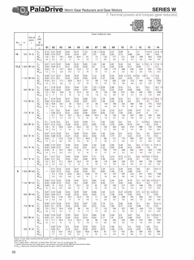
Values in red state nominal thermal power P tN (ambient temperature 40 °C , c ontinuousduty see c h. 4).For n1 higher than 1 400 min-1 or lower than 355 min-1 see ch. 6 and page 28.1) Values given for train of 2-stage gears are nominal; see page 28 for effective transmission ratios .2) M2max represents maximum torque peak the gear reduc er will withstand.
7 - Nominal powers and torques (gear reduc ers )
G ear reduc er s ize
01 02 03 04 05 06 07 08 09 10 11 12 13 14
nN2 n1min-1
Train ofgears
i
1)
P[kW]
M[daN m]
2)
PN1 0,12 0,21 0,39 0,63 0,75 1,22 1,46 1,1 2,42 3,27 3,89 6 7,1 11,9 10 21,8 1614,5 355 V 25 PN2 0,08 0,14 0,27 0,45 0,54 0,9 1,07 1,82 2,63 3,13 4,88 5,8 29,9 18,4
MN2 5,4 9,5 18,1 30,6 36,4 61 72 123 177 211 328 390 663 1236M2max 8,8 16,2 29,7 55 59 102 111 202 302 333 577 626 1084 1997
PN1 0,07 0,15 0,27 0,46 0,54 0,85 1,02 1,69 2,87 3,42 5,6 6,6 5,1 10,1 8 17,8 1311,2 1 400 IV 125 PN2 0,04 0,09 0,17 0,31 0,36 0,58 0,7 1,19 2,05 2,44 4,11 4,89 27,7 13,7
MN2 3,62 8 14,7 26,5 31,6 51 60 103 174 208 356 423 663 1190M2max 5,3 13,4 25,9 47,5 52 90 97 171 301 327 583 634 1100 2013
PN1 0,08 0,17 0,31 0,49 0,59 0,94 1,12 1,92 3,24 3,85 3,1 5,8 4,8 6,9 4,8 11 7,7 15,61 120 IV 100 PN2 0,05 0,11 0,2 0,33 0,39 0,66 0,78 1,37 2,36 2,8 4,29 5,1 28,4 12,6
MN2 4,34 9,3 17,1 28,9 34,3 57 68 119 200 239 372 442 730 1092M2max 6,9 15,5 28,2 52 56 99 107 191 339 368 636 691 1201 1792
PN1 0,10 0,18 0,34 0,55 0,64 1,05 1,25 1,1 2,09 2,86 3,41 5,2 6,1 10,2 18,7 14900 IV 80 PN2 0,06 0,12 0,23 0,38 0,44 0,74 0,89 1,52 2,23 2,65 4,08 4,86 28,2 15,3
MN2 5,3 9,8 18,8 32 37,4 63 75 129 184 219 344 409 693 1288M2max 8,4 17 31,1 58 63 109 118 215 309 347 617 670 1149 2094
PN1 0,10 0,19 0,35 0,47 0,52 0,88 1,01 1,79 2,98 3,55 5,7 6,7 5,4 11,2 8,5 20,4 13710 IV 63 PN2 0,06 0,13 0,24 0,35 0,39 0,67 0,77 1,38 2,34 2,78 4,5 5,4 29,1 16,7
MN2 5,6 10,8 20,1 30 33,5 57 66 118 196 233 384 458 775 1423M2max 9,3 18,3 33,4 49,4 55 101 111 196 349 379 687 746 1286 2292
PN1 0,10 0,2 0,36 0,41 0,69 0,81 1,34 2,16 2,57 3,99 4,74 27,9 14,1710 V 63 PN2 — 0,06 0,12 0,23 0,26 0,46 0,54 0,92 1,53 1,83 2,92 3,47 26 11
MN2 5,1 10,1 19,7 22,1 38,8 45,5 78 130 155 247 294 505 929M2max 7,7 15,1 29,5 33 60 68 119 233 261 458 497 877 1625
PN1 0,10 0,16 0,3 0,5 0,55 0,94 1,1 1,82 3,02 3,6 5,9 7 5,4 10,2 18,6 14560 IV 50 PN2 0,07 0,12 0,22 0,38 0,42 0,72 0,85 1,42 2,39 2,84 4,74 5,6 8,5 15,6
MN2 5,8 10 18,8 32,9 36,2 63 73 124 203 242 410 488 732 1350M2max 9,9 16,9 32 59 62 113 122 217 366 397 735 798 1197 2204
PN1 0,07 0,13 0,25 0,4 0,48 0,76 0,91 1,46 2,44 2,9 4,73 5,6 9,5 16,9 14560 V 50 PN2 0,04 0,08 0,16 0,27 0,32 0,52 0,62 1,03 1,77 2,1 3,52 4,19 7,3 13,3
MN2 3,62 7 13,5 22,8 27,1 44,4 53 88 151 179 300 357 621 1135M2max 5,3 10,3 20,2 39,5 44,2 80 87 149 277 300 526 571 1007 1850
PN1 0,08 0,15 0,27 0,46 0,55 0,85 1,02 1,69 2,82 3,36 5,6 6,6 5,1 10,1 8 17,8 13450 V 40 PN2 0,05 0,09 0,17 0,31 0,37 0,6 0,71 1,22 2,05 2,44 4,19 4,99 7,8 14
MN2 4,34 8 14,7 26,5 31,6 51 60 103 174 208 356 423 663 1190M2max 6,9 13,4 25,9 47,5 52 90 97 171 301 327 583 634 1100 2013
PN1 0,10 0,17 0,3 0,49 0,58 0,93 1,11 1,9 3,14 3,73 3,1 5,7 6,8 4,8 10,9 7,7 15,4355 V 32 PN2 0,06 0,11 0,2 0,34 0,4 0,66 0,79 1,38 2,33 2,77 4,32 5,1 8,5 12,7
MN2 5,3 9,3 17,1 28,9 34,3 57 68 119 200 239 372 442 730 1092M2max 8,4 15,5 28,2 52 56 99 107 191 339 368 636 691 1201 1792
PN1 0,11 0,22 0,35 0,41 0,64 0,77 1,24 2,13 2,54 4,03 4,8 8,2 14,5 129 1 400 IV 160 PN2 — 0,07 0,13 0,22 0,26 0,42 0,5 0,84 1,48 1,76 2,88 3,43 6 11
MN2 7,2 13,9 23,8 28,1 45,8 54 91 157 187 312 371 653 1189M2max 10,3 20,2 39,6 44,3 81 91 156 284 308 558 606 1062 1907
PN1 0,06 0,12 0,23 0,38 0,45 0,72 0,85 1,43 2,45 2,91 4,79 5,7 4,4 8,8 6,9 15,4 111 120 IV 125 PN2 0,03 0,08 0,14 0,25 0,3 0,48 0,57 0,99 1,71 2,04 3,46 4,12 6,5 11,7
MN2 3,69 8 15,2 27 32,1 52 62 107 182 217 374 446 703 1270M2max 5,3 13,4 26,3 48,5 53 94 102 178 316 343 614 667 1157 2072
PN1 0,07 0,14 0,26 0,42 0,49 0,81 0,96 1,64 2,74 3,27 2,8 4,95 5,9 4,3 9,5 6,8 13,3900 IV 100 PN2 0,04 0,09 0,17 0,28 0,33 0,55 0,65 1,15 1,96 2,34 3,63 4,32 7,1 10,6
MN2 4,37 9,6 17,8 30,1 35,3 59 71 124 208 248 391 466 767 1141M2max 6,9 16,3 29,7 54 59 105 114 204 361 392 680 739 1258 1830
PN1 0,08 0,15 0,28 0,47 0,52 0,87 1,03 1,74 2,4 2,82 4,38 5,1 8,4 15,4 12710 IV 80 PN2 0,05 0,10 0,18 0,32 0,36 0,6 0,72 1,24 1,85 2,17 3,42 3,99 6,7 12,4
MN2 5,5 10,2 19,4 33,8 38 65 77 133 194 227 365 426 713 1326M2max 8,8 17,8 32,7 61 65 113 123 229 316 354 634 710 1227 2240
PN1 0,08 0,16 0,29 0,39 0,43 0,74 0,84 1,45 2,46 2,9 4,67 5,6 9,3 7,6 16,6 12560 IV 63 PN2 0,05 0,10 0,19 0,29 0,32 0,55 0,63 1,11 1,9 2,24 3,68 4,37 7,4 13,5
MN2 5,7 11,1 20,5 31,5 34,3 60 68 120 202 239 398 473 803 1457M2max 9,5 19,1 35 50 56 104 116 203 364 395 716 778 1370 2448
PN1 0,09 0,16 0,3 0,34 0,59 0,67 1,13 1,85 2,2 3,4 4,02 6,8 12,1560 V 63 PN2 — 0,05 0,1 0,19 0,21 0,38 0,43 0,75 1,28 1,52 2,43 2,87 4,98 9,2
MN2 5,2 10,4 20,2 22,6 40,6 46,4 81 137 163 261 309 535 984M2max 7,7 15,2 29,6 33,1 61 68 120 234 262 489 531 904 1720
7. Nominal powers and torques (gear reducers)Worm Gear Reducers and Gear Motors SERIES WPalaDrive

21
Values in red state nominal thermal power P tN (ambient temperature 40 °C , c ontinuousduty see c h. 4).For n1 higher than 1 400 min-1 or lower than 355 min-1 see ch. 6 and page 28.1) Values given for train of 2-stage gears are nominal; see page 28 for effective transmission ratios .2) M2max represents maximum torque peak the gear reduc er will withstand.
7 - Nominal powers and torques (gear reduc ers )
- G ear reduc er s ize
01 02 03 04 05 06 07 08 09 10 11 12 13 14
nN2 n1min-1
Train ofgears
i
1)
P[kW]
M[daN m]
2)
PN1 0,08 0,13 0,25 0,42 0,46 0,81 0,91 1,54 2,6 2,99 4,97 5,9 4,6 8,6 15,5 129,5 450 IV 50 PN2 0,05 0,10 0,18 0,31 0,34 0,61 0,69 1,19 2,03 2,34 3,95 4,67 7,1 12,9
MN2 6 10,2 19,2 34 36,8 66 75 128 215 248 425 503 762 1392M2max 10,4 17,3 33,5 61 62 119 127 224 388 418 766 832 1226 2281
PN1 0,06 0,11 0,21 0,35 0,41 0,65 0,77 1,24 2,09 2,49 4,03 4,8 8,2 14,5 12450 V 50 PN2 0,03 0,07 0,13 0,22 0,26 0,43 0,51 0,86 1,48 1,76 2,94 3,49 6,2 11,2
MN2 3,69 7,2 13,9 23,8 28,1 45,8 54 91 157 187 312 371 653 1189M2max 5,3 10,3 20,2 39,6 44,3 81 91 156 284 308 558 606 1062 1907
PN1 0,07 0,12 0,22 0,38 0,45 0,71 0,84 1,41 2,37 2,82 4,72 5,6 4,4 8,6 6,9 15,2 11355 V 40 PN2 0,04 0,07 0,14 0,25 0,3 0,49 0,58 1 1,69 2,02 3,48 4,14 6,5 11,8
MN2 4,37 8 15,2 27 32,1 52 62 107 182 217 374 446 703 1270M2max 6,9 13,4 26,3 48,5 53 94 102 178 316 343 614 667 1157 2072
PN1 0,07 0,14 0,25 0,28 0,5 0,56 1,34 2,18 2,59 4,04 4,8 3,9 7,8 6 10,87,1 1 400 IV 200 PN2 — 0,04 0,08 0,15 0,17 0,31 0,35 0,92 1,53 1,82 2,91 3,47 5,8 8,5
MN2 5,4 10,6 20,6 23 42,2 47,3 128 213 253 406 483 802 1181M2max 7,7 15,2 29,6 33,1 61 68 212 376 409 725 787 1344 1865
PN1 0,10 0,18 0,29 0,34 0,55 0,65 1,05 1,82 2,16 3,42 4,07 7 12,3 101 120 IV 160 PN2 — 0,06 0,11 0,18 0,21 0,35 0,42 0,7 1,24 1,47 2,39 2,84 5 9,1
MN2 7,3 14,3 24,7 28,9 47,6 57 95 165 195 323 385 677 1236M2max 10,3 20,3 39,6 44,4 81 91 160 297 322 572 621 1089 2007
PN1 0,05 0,11 0,19 0,33 0,38 0,61 0,72 1,2 2,07 2,46 4,06 4,83 3,9 7,6 6,1 13,4 9,6900 IV 125 PN2 0,03 0,06 0,12 0,21 0,24 0,4 0,47 0,82 1,42 1,69 2,88 3,43 5,5 9,9
MN2 3,77 8,3 15,4 28,5 32,4 54 64 110 188 223 388 462 748 1340M2max 5,3 13,7 26,9 51 55 97 106 186 337 366 655 712 1210 2220
PN1 0,05 0,12 0,22 0,36 0,41 0,66 0,79 1,36 2,25 2,68 4,12 4,9 3,9 7,9 6 11710 IV 100 PN2 0,03 0,07 0,14 0,23 0,26 0,44 0,53 0,93 1,58 1,88 2,97 3,54 5,9 8,6
MN2 4,49 9,8 18,4 31,7 36,1 61 73 128 213 253 406 483 802 1181M2max 7,1 16,7 30,6 57 61 109 119 212 376 409 725 787 1344 1865
PN1 0,06 0,12 0,23 0,39 0,43 0,72 0,84 1,45 1,99 2,29 3,64 4,19 6,9 12,6560 IV 80 PN2 0,04 0,08 0,15 0,26 0,29 0,49 0,58 1,02 1,51 1,74 2,81 3,23 5,4 10,1
MN2 5,6 10,4 19,8 34,9 38,8 66 78 138 201 232 380 437 734 1362M2max 9 18,3 34,2 63 66 119 129 238 322 361 647 724 1263 2386
PN1 0,07 0,13 0,24 0,33 0,35 0,63 0,71 1,22 2,11 2,41 3,95 4,66 7,8 13,8 10450 IV 63 PN2 0,04 0,09 0,16 0,24 0,26 0,47 0,53 0,92 1,61 1,84 3,07 3,62 6,1 11,1
MN2 5,8 11,5 21 32,5 34,6 63 71 124 214 244 414 488 826 1491M2max 9,8 19,6 36,6 52 58 106 119 208 385 413 746 810 1425 2605
PN1 0,07 0,14 0,25 0,28 0,5 0,56 0,95 1,59 1,89 2,95 3,48 5,8 10,3450 V 63 PN2 — 0,04 0,08 0,15 0,17 0,32 0,35 0,62 1,07 1,28 2,05 2,42 4,15 7,7
MN2 5,4 10,6 20,6 23 42,2 47,3 83 144 171 275 323 555 1030M2max 7,7 15,2 29,6 33,1 61 68 120 234 262 491 548 952 1769
PN1 0,07 0,11 0,2 0,35 0,37 0,66 0,75 1,25 2,14 2,45 4,1 4,79 7,1 12,9355 IV 50 PN2 0,04 0,08 0,15 0,26 0,27 0,5 0,56 0,96 1,66 1,89 3,22 3,77 5,8 10,6
MN2 6,1 10,4 19,6 35,6 37,4 68 77 131 222 254 440 515 786 1448M2max 10,6 17,7 34,3 64 64 123 130 235 400 423 809 875 1250 2329
PN1 0,05 0,09 0,18 0,29 0,34 0,54 0,64 1,04 1,77 2,09 3,37 4,02 6,9 12,2 10355 V 50 PN2 0,03 0,05 0,11 0,18 0,21 0,35 0,42 0,7 1,23 1,45 2,4 2,86 5 9,2
MN2 3,77 7,3 14,3 24,7 28,9 47,6 57 95 165 195 323 385 677 1236M2max 5,3 10,3 20,3 39,6 44,4 81 91 160 297 322 572 621 1089 2007
PN1 0,98 1,67 1,98 3,28 3,91 6,2 11 8,55,6 1 400 IV 250 PN2 — — — — — — — 0,65 1,12 1,33 2,29 2,72 4,45 8
MN2 114 195 230 398 474 775 1400M2max 193 351 381 696 756 1289 2319
PN1 0,06 0,12 0,21 0,24 0,42 0,47 1,12 1,85 2,17 3,41 4,06 6,5 5,4 9,11 120 IV 200 PN2 — 0,03 0,06 0,12 0,14 0,25 0,28 0,76 1,27 1,49 2,42 2,88 4,74 7,1
MN2 5,5 10,8 21 23,5 43,1 48,2 132 220 259 421 501 826 1228M2max 7,7 15,2 29,6 33,1 61 68 220 391 425 754 819 1430 1948
PN1 0,08 0,15 0,25 0,29 0,47 0,55 0,89 1,59 1,82 2,94 3,44 5,9 10,5 8,9900 IV 160 PN2 — 0,05 0,09 0,15 0,17 0,29 0,34 0,58 1,06 1,22 2,01 2,35 4,19 7,6
MN2 7,5 14,7 26,1 29,5 49,5 58 97 175 201 339 396 706 1284M2max 10,5 20,7 40,4 45,3 83 93 163 315 343 610 662 1162 2098
PN1 0,04 0,09 0,16 0,27 0,31 0,52 0,59 1 1,73 2,04 3,35 3,99 6,4 11,2 8,5710 IV 125 PN2 0,02 0,05 0,09 0,17 0,19 0,33 0,38 0,66 1,16 1,37 2,33 2,78 4,54 8,2
MN2 3,85 8,5 15,8 29,4 32,7 57 65 114 195 230 398 474 775 1400M2max 5,4 14 27,4 53 56 103 111 193 351 381 696 756 1289 2319
7. Nominal powers and torques (gear reducers)Worm Gear Reducers and Gear Motors SERIES WPalaDrive

22
Values in red state nominal thermal power P tN (ambient temperature 40 °C , c ontinuousduty see c h. 4).For n1 higher than 1 400 min-1 or lower than 355 min-1 see ch. 6 and page 28.1) Values given for train of 2-stage gears are nominal; see page 28 for effective transmission ratios .2) M2max represents maximum torque peak the gear reduc er will withstand.
7 - Nominal powers and torques (gear reduc ers )
G ear reduc er s ize
01 02 03 04 05 06 07 08 09 10 11 12 13 14
nN2 n1min-1
Train ofgears
i
1)
P[kW]
M[daN m]
2)
PN1 0,05 0,1 0,18 0,3 0,33 0,56 0,65 1,13 1,88 2,21 3,43 4,08 6,6 5,4 9,15,6 560 IV 100 PN2 0,03 0,06 0,11 0,19 0,21 0,37 0,43 0,76 1,29 1,52 2,43 2,89 4,77 7,1
MN2 4,6 10 18,7 32,6 36,6 64 74 132 220 259 421 501 826 1228M2max 7,2 17,1 31,9 59 61 115 123 220 391 425 754 819 1430 1948
PN1 0,05 0,1 0,19 0,33 0,36 0,62 0,7 1,21 1,71 1,92 3,07 3,54 5,9 10,5450 IV 80 PN2 0,03 0,07 0,12 0,22 0,23 0,41 0,47 0,84 1,28 1,44 2,34 2,7 4,56 8,3
MN2 5,6 10,8 20,2 36,7 39,4 70 80 141 212 238 395 454 768 1402M2max 9,2 18,7 35,1 66 67 123 134 250 329 369 661 740 1290 2484
PN1 0,05 0,11 0,19 0,27 0,28 0,52 0,57 0,98 1,74 1,97 3,33 3,8 6,4 11,3 9,1355 IV 63 PN2 0,03 0,07 0,13 0,2 0,2 0,38 0,42 0,74 1,31 1,49 2,56 2,92 4,97 9
MN2 6 11,6 21,3 33,4 34,7 65 73 126 220 249 437 499 849 1531M2max 10,2 20,1 37,5 53 59 108 121 212 397 417 786 848 1481 2709
PN1 0,06 0,11 0,21 0,23 0,41 0,46 0,78 1,36 1,57 2,54 2,92 4,81 8,7355 V 63 PN2 — 0,03 0,06 0,12 0,14 0,25 0,28 0,5 0,9 1,04 1,73 1,99 3,38 6,3
MN2 5,5 10,8 21 23,5 43,1 48,2 85 153 176 293 337 572 1067M2max 7,7 15,2 29,6 33,1 61 68 120 234 262 491 550 959 1856
PN1 0,73 1,29 1,49 2,46 2,81 4,81 8,54,5 1 400 IV 315 PN2 — — — — — — — 0,46 0,84 0,97 1,65 1,89 3,32 6,1
MN2 100 182 211 359 411 724 1322M2max 166 326 356 647 703 1235 2235
PN1 0,83 1,42 1,65 2,73 3,25 5,3 9,2 7,71 120 IV 250 PN2 — — — — — — — 0,54 0,93 1,08 1,86 2,22 3,68 6,6
MN2 117 202 235 405 482 802 1440M2max 203 364 396 724 786 1368 2467
PN1 0,05 0,1 0,18 0,2 0,35 0,39 0,94 1,57 1,81 2,89 3,43 5,5 7,7900 IV 200 PN2 — 0,03 0,05 0,1 0,11 0,21 0,23 0,62 1,06 1,23 2,01 2,38 3,92 5,9
MN2 5,6 11 21,4 23,9 43,9 49,1 135 230 264 435 516 851 1274M2max 7,8 15,5 30,1 33,7 62 69 230 413 446 784 851 1487 1984
PN1 0,07 0,13 0,21 0,24 0,4 0,45 0,74 1,33 1,54 2,51 2,87 4,9 8,7710 IV 160 PN2 — 0,04 0,07 0,13 0,14 0,24 0,28 0,47 0,87 1 1,68 1,93 3,39 6,2
MN2 7,6 14,9 26,9 29,8 52 59 100 182 211 359 411 724 1322M2max 10,7 21,1 41,1 46,1 84 94 166 326 356 647 703 1235 2235
PN1 0,03 0,07 0,13 0,23 0,25 0,43 0,49 0,83 1,44 1,68 2,75 3,27 5,3 9,3 7,7560 IV 125 PN2 0,02 0,04 0,08 0,14 0,15 0,27 0,31 0,54 0,95 1,1 1,87 2,23 3,7 6,7
MN2 3,92 8,7 16,2 30,8 33,5 59 67 117 202 235 405 482 802 1440M2max 5,5 14,2 27,9 54 57 106 114 203 364 396 724 786 1368 2467
PN1 0,04 0,08 0,15 0,25 0,27 0,47 0,54 0,95 1,6 1,84 2,91 3,45 5,5 7,7450 IV 100 PN2 0,02 0,05 0,09 0,16 0,17 0,3 0,35 0,62 1,08 1,25 2,02 2,39 3,95 5,9
MN2 4,79 10,2 19 33,6 37 66 75 135 230 264 435 516 851 1274M2max 7,3 17,5 32,7 61 62 118 126 230 413 446 784 851 1487 1984
PN1 0,04 0,08 0,15 0,27 0,29 0,51 0,58 1 1,41 1,55 2,58 2,94 4,83 8,7355 IV 80 PN2 0,03 0,05 0,1 0,18 0,19 0,34 0,38 0,68 1,04 1,14 1,94 2,21 3,7 6,8
MN2 5,7 11,1 20,5 37,8 40,1 72 82 145 218 240 415 473 790 1444M2max 9,6 19,5 35,9 68 68 127 137 257 335 375 672 753 1313 2563
PN1 0,61 1,09 1,25 2,09 2,41 4 7,23,55 1 120 IV 315 PN2 — — — — — — — 0,38 0,7 0,8 1,37 1,58 2,71 5
MN2 103 189 216 373 429 738 1366M2max 169 331 367 672 730 1283 2372
PN1 0,7 1,22 1,38 2,3 2,72 4,42 7,8900 IV 250 PN2 — — — — — — — 0,44 0,79 0,89 1,54 1,82 3,03 5,5
MN2 120 213 241 417 494 820 1495M2max 209 383 410 751 815 1420 2615
PN1 0,04 0,08 0,15 0,16 0,29 0,32 0,77 1,3 1,49 2,44 2,81 4,55 6,3710 IV 200 PN2 — 0,02 0,04 0,08 0,09 0,17 0,19 0,5 0,86 0,99 1,67 1,92 3,19 4,8
MN2 5,7 11,2 21,7 24,3 44,6 50 136 237 270 459 528 876 1318M2max 8 15,7 30,6 34,3 63 70 236 426 450 826 893 1544 2015
PN1 0,05 0,1 0,18 0,19 0,33 0,37 0,61 1,11 1,27 2,11 2,42 4,02 7,2560 IV 160 PN2 — 0,03 0,06 0,1 0,11 0,2 0,22 0,38 0,71 0,81 1,38 1,59 2,73 5
MN2 7,7 15,2 28,2 30,5 54 61 103 189 216 373 429 738 1366M2max 10,9 21,4 41,8 46,8 86 96 169 331 367 672 730 1283 2372
PN1 0,03 0,06 0,11 0,19 0,21 0,37 0,41 0,7 1,25 1,41 2,31 2,74 4,44 7,9 6,7450 IV 125 PN2 0,01 0,03 0,06 0,12 0,12 0,23 0,26 0,45 0,8 0,91 1,55 1,83 3,04 5,5
MN2 3,98 9 16,6 31,7 33,8 62 69 120 213 241 417 494 820 1495M2max 5,6 14,5 28,4 55 57 111 118 209 383 410 751 815 1420 2615
7. Nominal powers and torques (gear reducers)Worm Gear Reducers and Gear Motors SERIES WPalaDrive

23
Values in red state nominal thermal power P tN (ambient temperature 40 °C , c ontinuousduty see c h. 4).For n1 higher than 1 400 min-1 or lower than 355 min-1 see ch. 6 and page 28.1) Values given for train of 2-stage gears are nominal; see page 28 for effective transmission ratios .2) M2max represents maximum torque peak the gear reduc er will withstand.
7 - Nominal powers and torques (gear reduc ers )
G ear reduc er s ize
01 02 03 04 05 06 07 08 09 10 11 12 13 14
nN2 n1min-1
Train ofgears
i
1)
P[kW]
M[daN m]
2)
PN1 0,03 0,07 0,12 0,2 0,22 0,39 0,44 0,77 1,33 1,52 2,46 2,83 4,58 6,43,55 355 IV 100 PN2 0,02 0,04 0,07 0,13 0,14 0,25 0,28 0,5 0,88 1,01 1,68 1,93 3,21 4,82
MN2 4,98 10,4 19,3 34,6 37,4 68 77 136 237 270 459 528 876 1318M2max 7,4 18,2 34 62 62 122 129 236 426 450 826 893 1544 2015
PN1 0,51 0,94 1,05 1,77 2,03 3,37 62,81 900 IV 315 PN2 — — — — — — — 0,31 0,59 0,66 1,14 1,31 2,23 4,14
MN2 105 198 222 386 443 755 1402M2max 172 337 377 696 754 1331 2463
PN1 0,57 1,01 1,14 1,94 2,22 3,62 6,5710 IV 250 PN2 — — — — — — — 0,36 0,64 0,72 1,28 1,46 2,44 4,48
MN2 122 219 246 438 501 838 1540M2max 218 395 412 778 850 1473 2713
PN1 0,03 0,07 0,12 0,13 0,24 0,27 0,62 1,09 1,19 2,02 2,29 3,71 5,2560 IV 200 PN2 — 0,02 0,03 0,06 0,07 0,13 0,15 0,4 0,71 0,78 1,36 1,54 2,56 3,85
MN2 5,7 11,3 22,1 24,7 45,3 51 139 248 271 472 536 891 1343M2max 8,1 16 31,1 34,8 64 72 242 446 460 840 911 1622 2044
PN1 0,04 0,09 0,15 0,16 0,28 0,32 0,52 0,96 1,07 1,78 2,04 3,39 6,1450 IV 160 PN2 — 0,02 0,05 0,09 0,09 0,17 0,19 0,31 0,6 0,67 1,15 1,32 2,24 4,16
MN2 7,9 15,5 29 30,7 56 63 105 198 222 386 443 755 1402M2max 11,1 21,8 42,6 47,7 87 98 172 337 377 696 754 1331 2463
PN1 0,02 0,05 0,09 0,16 0,16 0,3 0,34 0,57 1,03 1,16 1,95 2,23 3,64 6,5355 IV 125 PN2 0,01 0,03 0,05 0,1 0,1 0,19 0,21 0,36 0,65 0,73 1,28 1,47 2,45 4,51
MN2 4,05 9,4 17,3 32,6 33,8 64 71 122 219 246 438 501 838 1540M2max 5,7 14,7 28,9 56 57 114 119 218 395 412 778 850 1473 2713
PN1 0,43 0,78 0,85 1,5 1,7 2,77 52,24 710 IV 315 PN2 — — — — — — — 0,26 0,48 0,52 0,94 1,07 1,8 3,36
MN2 110 203 223 405 460 772 1444M2max 174 342 378 718 774 1397 2554
PN1 0,46 0,85 0,92 1,61 1,82 2,96 5,3560 IV 250 PN2 — — — — — — — 0,28 0,53 0,57 1,03 1,17 1,96 3,59
MN2 124 229 248 451 510 853 1562M2max 223 413 422 790 850 1536 2812
PN1 0,03 0,05 0,1 0,11 0,2 0,22 0,5 0,91 0,98 1,72 1,94 3,15 4,27450 IV 200 PN2 — 0,01 0,03 0,05 0,06 0,11 0,12 0,32 0,59 0,63 1,14 1,28 2,13 3,15
MN2 5,8 11,5 22,4 25,1 46,1 52 138 254 272 494 556 923 1364M2max 8,2 16,2 31,6 35,4 65 73 249 458 463 850 921 1662 2073
PN1 0,04 0,07 0,12 0,13 0,23 0,26 0,43 0,79 0,87 1,51 1,71 2,78 5355 IV 160 PN2 — 0,02 0,04 0,07 0,07 0,13 0,15 0,26 0,48 0,53 0,95 1,08 1,81 3,38
MN2 8 15,7 29,5 31,1 58 64 110 203 223 405 460 772 1444M2max 11,3 22,1 43,2 48,4 89 99 174 342 378 718 774 1397 2554
PN1 0,35 0,64 0,68 1,24 1,39 2,29 4,131,81 560 IV 315 PN2 — — — — — — — 0,21 0,39 0,41 0,76 0,86 1,46 2,73
MN2 112 209 224 416 469 795 1484M2max 177 347 381 728 774 1426 2671
PN1 0,38 0,71 0,75 1,35 1,52 2,49 4,5450 IV 250 PN2 — — — — — — — 0,24 0,44 0,46 0,86 0,96 1,61 3
MN2 128 236 249 465 522 874 1628M2max 226 424 424 800 850 1573 2931
PN1 0,02 0,04 0,08 0,09 0,16 0,18 0,42 0,75 0,79 1,39 1,56 2,62 3,44355 IV 200 PN2 — 0,01 0,02 0,04 0,05 0,09 0,1 0,26 0,48 0,5 0,91 1,02 1,75 2,52
MN2 5,9 11,7 22,8 25,5 46,7 52 144 263 275 500 560 961 1384M2max 8,4 16,5 32,1 35,9 66 74 252 468 467 850 921 1730 2102
PN1 0,29 0,54 0,56 1,03 1,15 1,95 3,51,41 450 IV 315 PN2 — — — — — — — 0,17 0,32 0,34 0,63 0,7 1,22 2,26
MN2 116 216 226 428 477 827 1532M2max 179 352 384 738 774 1446 2757
PN1 0,32 0,58 0,6 1,11 1,24 2,03 3,71355 IV 250 PN2 — — — — — — — 0,19 0,36 0,37 0,7 0,78 1,3 2,43
MN2 131 243 251 481 534 894 1666M2max 226 428 427 810 850 1597 2995
PN1 0,24 0,45 0,45 0,85 0,94 1,59 2,881,12 355 IV 315 PN2 — — — — — — — 0,14 0,26 0,27 0,51 0,57 0,98 1,84
MN2 120 225 229 442 489 845 1579M2max 181 356 385 748 774 1465 2769
7. Nominal powers and torques (gear reducers)Worm Gear Reducers and Gear Motors SERIES WPalaDrive

24
Summary of transmission ratios i and torques validfor n1 90 min-1
1) For these transmiss ion ratios (whic h will transmit higher torques at lower speeds) torqueinc reases further as n1 dec reases , as s tated in table A c h. 11; for s izes 32 and 40 c on-sult us .
2) G ear ratio of input c ylindric al gear pair.3) For s izes 09 and 10 it is equal to 3,13.
G ear reduc er s ize
01 02 03 04 05 06 07 08 09 10 11 12 13 14
i M[daN m]
MN2 e M2max sono rispettivamente il momento torc ente nominale e dipic c o validi per n1 90 min-1.
W 1
G ear reduc er s izeG ear reduc er s ize
01 02 03 04,05 06 07 08 09,10 11 12 13 14
iN M
[daN m]
01 02, 03, 04, 05, 11, 12,09, 10 06, 07, 13, 14
08i 2) i 2) i 2) i 2)
50 51,8 2,59 49,9 3,123) 50,9 3,18 50,8 3,17 MN2 7,3 13 24,1 44,3 78 84 144 272 487 540 824 1 495M2max 11,5 19,5 37,7 70 133 138 250 455 880 953 1383 2 406
63 64,8 62,4 63,6 63,5 MN2 7,1 13,7 25 41 76 86 151 277 487 540 975 1 718M2max 10,9 21,4 40,2 65 119 128 233 453 880 910 1 697 2 863
80 82,9 78 79,5 79,3 MN2 6,7 13,3 24,4 47,5 80 90 160 260 487 540 925 1 743M2max 10 20,2 38 73 133 141 268 384 735 824 1 597 2 802
100 104 99,8 102 102 MN2 5,7 12,6 23,2 43,3 78 88 155 2951) 500 560 1 000 1 438M2max 8,1 18,6 34,9 66 128 131 252 468 850 921 1 736 2 227
125 130 125 127 127 MN2 4,38 11,3 21,2 40,6 75 85 146 273 487 540 975 1 8001)
M2max 6,2 15,9 31,2 60 119 124 226 428 820 850 1 597 3 034
160 – 156 159 159 MN2 – 8,6 16,9 33 68 76 133 252 487 540 925 1 748M2max 12,1 23,8 49 95 107 188 385 774 774 1 470 2 769
200 – 197 200 – MN2 – 6,3 12,5 26,4 50 56 – – – – – –M2max 8,9 17,7 38,5 71 79
200 – 203 6,36 204 6,38 204 6,38 MN2 – – – – – – 156 300 500 560 1 000 1 483M2max 252 468 850 921 1 736 2 291
250 – 254 255 255 MN2 – – – – – – 150 289 487 540 975 1 900M2max 226 428 820 850 1 597 3 134
315 – 318 319 319 MN2 – – – – – – 137 268 487 540 975 1 850M2max 193 385 774 774 1 470 2 769
W 2
10 MN2 6,1 11,1 20,4 37,5 38,7 72 80 132 229 252 434 493 – –M2max 11 20 36,7 68 68 129 136 238 411 428 781 888
13 MN2 6,1 11,2 20,7 37,3 38,5 73 81 139 243 265 468 530 886 –M2max 11 20,1 37,3 67 67 131 137 250 410 451 842 902 1 537
16 MN2 5,9 10,7 19,9 36,6 37,5 70 78 134 233 255 464 526 824 1 4951)
M2max 9,2 18 35,4 66 66 126 132 241 420 434 835 894 1 274 2 374
20 MN2 6,41) 11,61) 21,31) 34,9 35,4 67 74 127 231 252 450 510 863 1 5631)
M2max 11,5 20,9 38,4 53 60 110 123 216 416 428 810 866 1 554 2 813
25 MN2 6,2 11,3 20,8 39,41) 40,61) 741) 821) 1461) 225 242 427 482 817 1 5081)
M2max 10,9 20,1 37,4 71 71 132 140 263 341 381 683 766 1 335 2 605
32 MN2 5,9 10,6 19,6 36,1 37,8 70 78 139 2481) 2711) 4721) 5361) 8911) 1 3431)
M2max 9,9 18,6 34,9 65 65 125 131 242 446 460 840 911 1 622 2 044
40 MN2 5,4 9,8 17,9 33,5 34,4 65 72 124 229 248 451 510 853 1 5621)
M2max 7,7 14,9 29,3 57 58 117 119 223 413 422 790 850 1 536 2 812
50 MN2 4,17 8,1 15,9 30 31,2 60 66 112 209 224 416 469 795 1 4841)
M2max 5,9 11,4 22,4 43,8 49 90 100 177 347 381 728 774 1 426 2 671
63 MN2 – 6 11,8 23 25,6 47,3 53 93 182 201 379 426 707 1 3531)
M2max 8,5 16,7 32,5 36,4 67 75 131 257 288 540 604 1 054 2 056
Summary of transmission ratios i and torques validfor n1 90 min-1
MN2 e M2max sono rispettivamente il momento torcente nominale e dipicco validi per n1 90 min-1.
7. Nominal powers and torques (gear reducers)Worm Gear Reducers and Gear Motors SERIES WPalaDrive

25
Unless otherwise stated, gear reducers are supplied in mounting position B3 (B3 and B8for sizes 64) which, being standard, is omitted from the designation.1) Sizes 13 and 14 in mounting position B7 , with n1 710 min -1 carry a price addition.>
W 011 ... 071
W 081 ... 141
Mounting positions - direction of rotation - and oil quantities [l]Grandezza B3 B6, B7 B8 V5, V6
Size
01, 81 0,16 0,22 0,16 0,1602, 81 0,26 0,35 0,26 0,2603, 81 0,46 0,62 0,42 0,42
04, 05 0,86 1,15 0,82 0,8206, 07 1,36 2,22 1,72 1,32
08, 8 1 1,9 5,4 4,2 3,709,10 3,4 10,4 8,2 5,711, 12 5,6 18,4 15,2 10,7
13, 126 9,56 33,2 30,2 20214, 126 17,56 57,2 51,2 342
B3 B6 B7 B8 V5 V6
B3 B6 B71) B8 V5 V6
Designstandard UO3Adouble extension wor m UO3Dreduced wor m shaft end UO3B1)
double extension wor mwith r educed shaft end UO3C1)
Designstandard UO2A5)
reduced worm shaft end UO2B1) 5)
1) Only for i 16.2) Working length of thread 2 · F.3) Holes turned through 22° 30’ with respect to the drawing.4) Size 40: c1 = 57,5; size 200: c1 = 235; size 250: c1 = 287.5) Prearranged design for double extension worm shaft (see ch. 2).6) Holes turned through 45° with respect to the drawing.7) Tolerance t8.
a A B D c d e c d e Y1 d1 e1 F G0 G1 G2 H H0 H1 h h0 K L L1 M N P Q T U V0 W1 Y1 ZØ Ø Ø Ø h11 h11 h12 h11 h11 Ø Ø Ø Ø Ø
MassSize
H7 UO3B1) UO3C1) h6 maxkg
c1 UO2B1) 2) G01 32 61 52 19 51,54) 14 25 50,5 10 14 112 11 20 M56) – – – 71 48 34,5 39 80 7,5 10 8,5 75 557) 90 3,5 91 66 – 119 124 39 3
02 40 70 62 24 59,54) 16 30 59,5 12 14 130 14 25 M66) – – – 82 56 41,5 42 96 9,5 12 10,5 85 687) 105 3,5 106 80 – 138 146 46 5
03 50 86 75 28 70,5, 19 30 70,5 12 14 152 16 30 M66) – – – 100 67 49 50 117 9,5 13 12,5 100 857) 120 3,5 126 95 – 167 168 53 9
04, 05 63 102 90 32 83,54) 19 40 85,5 17 17 182 19 30 M8 – – – 125 80 58,5 62 143 11,5 16 14,5 100 807) 120 3,5 151 114 – 205 203 63 14
06 80 132 106 38 103,54) 24 50 105,5 17 17 222 24 36 M10 – – – 150 100 69,5 70 180 14,5 20 17,5 130 1007) 160 3,5 189 135 – 250 253 75 2407 40 ,54) ,5 ,5 ,5 –
08 100 180 131 48 130,54) 28 60 130,5 20 21 331 28 42 M12 180 122 11 180 125 84,5 80 225 16,5 23 – 165 1307) 200 3,5 236 165 45 305 370 90 43
09,10 125 225 155 60 155,54) 32 80 155,5 25 26 402 32 58 M128 221 148 15 225 150 99,5 100 275 18,5 28 – 215 1807) 250 4,5 287 194 50 375 456 106 174
11 160 272 183 70 187,54) 38 80 181,5 35 36 472 38 58 M148 225 178 15 280 180 118,5 120 340 22,5 33 – 265 2307) 300 4,5 345 232 60 460 522 125 13012 75 ,54) ,5 ,5 ,5
13 200 342 214 90 2324),5 48 110 226,5 35 36 586 48 82 M168 324 222 20 335 225 137,5 135 425 27,5 40 – 300 2507) 350 5,5 431 270 80 560 666 150 233
14 250 425 250 110 2924),0 )60 105 281,5 40 46 706 55 82 M208 3) 379 277 20 410 280 163 160 530 33,5 50 – 400 3507)) 450 5,5 537 320 80 690 776 180 382
UT.C
685
UT.C
686
UT.C 687
08 09 ... 14
8.Designs, dimensions, mountingpositions and oil quantities
8. Designs, dimensions, mountingpositions and oil quantities
Worm Gear Reducers and Gear Motors SERIES WPalaDrive

26
a a1 A B c c1 D d e d1 e1 F G G0 G1 G2 H H0 H1 h h0 K L L1 M N P P1 Q T U V0 W1 Y1 ZØ Ø Ø Ø Ø Ø Ø Ø Ø Mass
S ize
H7 h11 h11 h12 h11 h11 h6 max kg
2)
01 32 32 61 52 81 51,0 19 11* 20* 11 20 M54) 76 – – – 71 48 34,5 71 48 7,0 10 8,5 75 555) 90 1406) 3,0 91 66 – 124 149 39 5
02 40 40 70 62 96 57,5 24 11* 23* 14 25 M64) 87 – – – 82 56 41,5 82 56 9,5 12 10,5 85 685) 105 1406) 3,0 106 80 – 138 175 46 7
03 50 40 86 75 107 70,5 28 11* 23* 16 30 M64) 98 – – – 100 67 49,5 90 77 9,5 13 12,5 100 855) 120 1406) 3,0 126 95 – 167 197 53 11
04, 05 63 50 102 90 127 83,0 32 14* 30* 19 30 M8 118 – – – 125 80 58,5 112 93 11,5 16 14,5 100 805) 120 1606) 3,0 151 114 – 205 237 63 17
06 80 50 132 106 147 103,0 38 14* 30* 24 36 M10 138 – – – 150 100 69,5 120 130 14,0 20 17,5 130 1105) 160 1606) 3,5 189 135 – 250 277 75 2707 40
08 100 63 180 131 181 130,0 48 19* 40* 28 42 M12 170 180 122 11 180 125 84,5 143 162 16,0 23 – 165 1305) 200 2006) 3,5 236 165 45 305 401 90 48
09, 10 125 80 225 155 216 155,0 60 24* 50* 32 58 M128 205 221 148 15 225 150 99,5 180 195 18,0 28 – 215 1805) 250 2006) 4,0 287 194 50 375 487 106 82
11 160 100 272 183 258 187,0 70 28* 60* 38 58 M148 247 255 178 15 280 180 118,5 220 240 22,0 33 – 265 2305) 300 2506) 4,0 345 232 60 460 573 125 14612 75
13 200 100 342 214 303 235,0 90 28* 60* 48 82 M168 292 324 222 20 335 225 137,5 235 325 27,0 40 – 300 2505) 350 2506) 5,0 431 270 80 560 687 150 249
14 250 125 425 250 373 287,0 110 32* 80* 55 82 M208 3) 360 379 277 20 410 280 163,5 285 405 33,0 50 – 400 3505) 450 3006) 5,0 537 320 80 690 832 180 408
1) Prearranged des ign for worm shaft extens ion (see c h. 2).2) Working length of thread 2 · F.3) Holes turned through 22° 30’ with respec t to the drawing.4) Holes turned through 45° with respec t to the drawing.5) Toleranc e t8.6) S qure flange: for dimensions see c h. 15.* When iN 200 the shaft end will be:
s ize 100: d = 16, e = 30;s izes 125, 126: d = 19, e = 40;s izes 160 .. . 200: d = 24, e = 50.
Mounting positions - direction of rotation - and oil quantities [l]
B3 B6, B7 B8 V5, V6S ize
01, 81 0,26 0,25 0,20 0,2602, 81 0,32 0,45 0,32 0,3203, 81 0,56 0,72 0,50 0,52
04, 05 1,86 1,35 1,82 1,8206, 07 1,56 2,52 2,72 1,52
08, 8 1 2,1 6,3 4,5 3,309, 10 3,8 11,6 8,8 6,311, 12 6,5 20,8 16,5 11,2
13, 126 10,46 38,2 31,5 21,214, 126 18,36 67,2 53,2 35,7
B3 B6 B7 B8 V5 V6
B3 B6 B71) B8 V5 V6
W 012 ... 072
W 082 ... W142
Designstandard UO3A
1)
worm extens ion UO3D
1)
Designstandard UO2A1)
)
UT.
C 6
98
UT.
C 6
99
UT.C 690
0809 ... 14
8.Designs, dimensions, mountingpositions and oil quantities
Unless otherwise stated, gear reducers are supplied in mounting position B3 (B3 and B8for sizes 64) which, being standard, is omitted from the designation.1) Sizes 08 ... 14 in mounting position B6 carry a price addition.
Worm Gear Reducers and Gear Motors SERIES WPalaDrive

27
9 - Manufacturing programme (gearmotors)
P1 n2 P2 M2 fs ikW min-1 kW daN m Gear reducer - Motor
1) 2)
0,09 2,06 0,05 23,3 0,8 MW 033 - 63 A 6 10,9 x40
2,58 0,05 19,7 1 MW 033 - 63 A 6 10,9 x32
3,3 0,06 15,9 0,71 MW 023 - 63 A 6 10,9 x253,3 0,06 16,2 1,32 MW 033 - 63 A 6 10,9 x25
4,12 0,06 13,3 0,9 MW 023 - 63 A 6 10,9 x204,12 0,06 13,5 1,6 MW 033 - 63 A 6 10,9 x204,08 0,05 11,3 1 MW 032 - 63 A 6 23,5 x63
5,07 0,06 10,6 1 MW 023 - 63 A 6 27,11 x255,14 0,05 9,4 0,8 MW 022 - 63 A 6 23,5 x505,07 0,06 10,8 1,9 MW 033 - 63 A 6 27,11 x255,14 0,05 9,6 1,5 MW 032 - 63 A 6 23,5 x50
6,33 0,06 8,8 1,32 MW 023 - 63 A 6 27,11 x206,43 0,05 8 1,06 MW 022 - 63 A 6 23,5 x406,43 0,06 8,2 1,9 MW 032 - 63 A 6 23,5 x40
7,92 0,07 7,9 1,32 MW 023 - 63 A 6 27,11 x168,04 0,06 6,8 1,4 MW 022 - 63 A 6 23,5 x328,04 0,06 6,9 2,65 MW 032 - 63 A 6 23,5 x32
8,68 0,05 6 0,71 MW 012 - 63 A 6 22,59 x40
10,3 0,06 5,5 1,8 MW 022 - 63 A 6 23,5 x25
10,9 0,06 5,1 1,06 MW 012 - 63 A 6 22,59 x32
12,9 0,06 4,59 2,36 MW 022 - 63 A 6 23,5 x20
13,9 0,06 4,16 1,32 MW 012 - 63 A 6 22,59 x2514,3 0,05 3,62 1,4 MW 021 - 63 A 6 63
17,4 0,06 3,45 1,6 MW 012 - 63 A 6 22,59 x2018 0,06 3 1,12 MW 011 - 63 A 6 5018 0,06 3,08 2,12 MW 021 - 63 A 6 50
21,7 0,07 3,02 1,7 MW 012 - 63 A 6 22,59 x1622,5 0,06 2,53 1,6 MW 011 - 63 A 6 40
28,1 0,06 2,12 2 MW 011 - 63 A 6 3236 0,07 1,73 2,5 MW 011 - 63 A 6 25
0,12 2,58 0,07 26,3 0,75 MW 033 - 63 B 6 10,9 x32
3,21 0,07 20,6 0,8 MW 033 - 63 A 4 10,9 x403,3 0,07 21,6 1 MW 033 - 63 B 6 10,9 x25
4,01 0,07 17,4 1,12 MW 033 - 63 A 4 10,9 x324,12 0,08 18 1,25 MW 033 - 63 B 6 10,9 x204,08 0,06 15 0,75 MW 032 - 63 B 6 23,5 x63
5,13 0,08 14 0,8 MW 023 - 63 A 4 10,9 x255,13 0,08 14,3 1,4 MW 033 - 63 A 4 10,9 x255,14 0,07 12,8 1,18 MW 032 - 63 B 6 23,5 x50
6,41 0,08 11,7 1 MW 023 - 63 A 4 10,9 x206,43 0,07 10,7 0,8 MW 022 - 63 B 6 23,5 x406,41 0,08 11,8 1,8 MW 033 - 63 A 4 10,9 x206,35 0,07 10,2 1,06 MW 032 - 63 A 4 23,5 x636,43 0,07 10,9 1,4 MW 032 - 63 B 6 23,5 x40
7,88 0,08 9,3 1,12 MW 023 - 63 A 4 27,11 x258 0,07 8,4 0,85 MW 022 - 63 A 4 23,5 x508,04 0,08 9 1,06 MW 022 - 63 B 6 23,5 x327,88 0,08 9,5 2,12 MW 033 - 63 A 4 27,11 x258 0,07 8,7 1,6 MW 032 - 63 A 4 23,5 x508,04 0,08 9,2 2 MW 032 - 63 B 6 23,5 x32
9,85 0,08 7,7 1,4 MW 023 - 63 A 4 27,11 x2010 0,07 7,1 1,12 MW 022 - 63 A 4 23,5 x4010,3 0,08 7,4 1,32 MW 022 - 63 B 6 23,5 x2510 0,08 7,3 2 MW 032 - 63 A 4 23,5 x40
10,9 0,08 6,7 0,8 MW 012 - 63 B 6 22,59 x32
12,3 0,09 6,9 1,4 MW 023 - 63 A 4 27,11 x1612,5 0,08 6 1,5 MW 022 - 63 A 4 23,5 x3212,9 0,08 6,1 1,7 MW 022 - 63 B 6 23,5 x20
13,5 0,08 5,4 0,8 MW 012 - 63 A 4 22,59 x4013,9 0,08 5,5 0,95 MW 012 - 63 B 6 22,59 x25
14,3 0,07 4,83 1,06 MW 021 - 63 B 6 6314,3 0,07 4,99 2 MW 031 - 63 B 6 63
16,9 0,08 4,51 1,06 MW 012 - 63 A 4 22,59x 3216 0,08 4,94 1,9 MW 022 - 63 A 4 23,5 x25
17,4 0,08 4,6 1,18 MW 012 - 63 B 6 22,59 x20
P1 n2 P2 M2 fs ikW min-1 kW daN m Gear reducer - Motor
1) 2)
0,12 18 0,08 4 0,85 MW 011- 63 B 6 5018 0,08 4,1 1,6 MW 021- 63 B 6 50
20 0,09 4,08 2,5 MW 022 - 63 A 4 13,5 x20
21,6 0,08 3,7 1,32 MW 012 - 63 A 4 12,59 x2522,5 0,08 3,37 1,18 MW 011 - 63 B 6 4022,2 0,08 3,29 1,5 MW 021 - 63 A 4 6322,5 0,08 3,44 2,12 MW 021 - 63 B 6 40
27 0,09 3,06 1,7 MW 012 - 63 A 4 12,59 x2028 0,08 2,7 1,18 MW 011 - 63 A 4 5028,1 0,08 2,83 1,5 MW 011 - 63 B 6 3228 0,08 2,77 2,12 MW 021 - 63 A 4 50
33,8 0,09 2,65 1,8 MW 012 - 63 A 4 12,59 x1635 0,08 2,27 1,6 MW 011 - 63 A 4 4036 0,09 2,31 1,9 MW 011 - 63 B 6 2535 0,08 2,32 2,8 MW 021 - 63 A 4 40
43,8 0,09 1,89 2 MW 011 - 63 A 4 3245 0,09 1,91 2,36 MW 011 - 63 B 6 20
56 0,09 1,54 2,5 MW 011 - 63 A 4 25
70 0,09 1,27 3,15 MW 011 - 63 A 4 20
87,5 0,1 1,08 3,35 MW 011 - 63 A 4 16
108 0,1 0,89 4 MW 011 - 63 A 4 13
140 0,1 0,7 4,75 MW 011 - 63 A 4 10
0,18 1,49 0,1 65 0,95 MW 063 - 71 A 6 12,1 x501,49 0,1 65 1,06 MW 073 - 71 A 6 12,1 x50
1,86 0,11 55 1,25 MW 063 - 71 A 6 12,1 x401,86 0,11 55 1,32 MW 073 - 71 A 6 12,1 x40
2,33 0,11 44,7 0,85 MW 043 - 71 A 6 12,1 x322,33 0,11 45,8 1,6 MW 063 - 71 A 6 12,1 x322,33 0,11 45,8 1,7 MW 073 - 71 A 6 12,1 x32
2,98 0,11 36,6 1,12 MW 043 - 71 A 6 12,1 x252,98 0,12 37,6 2 MW 063 - 71 A 6 12,1 x252,98 0,12 37,6 2,24 MW 073 - 71 A 6 12,1 x25
3,56 0,12 31,1 1,25 MW 043 - 71 A 6 10,1 x253,56 0,12 31,7 2,36 MW 063 - 71 A 6 10,1 x253,56 0,12 31,7 2,65 MW 073 - 71 A 6 10,1 x25
4,01 0,11 26 0,75 MW 033 - 63 B 4 10,9 x323,76 0,1 25,8 0,85 MW 042 - 71 A 6 13,8 x633,76 0,1 25,8 0,95 MW 052 - 71 A 6 13,8 x633,76 0,11 26,7 1,7 MW 062 - 71 A 6 13,8 x633,76 0,11 26,7 1,9 MW 072 - 71 A 6 13,8 x63
4,55 0,11 24 0,85 MW 033 - 71 A 6 17,91 x254,42 0,11 24,5 1,4 MW 043 - 71 A 6 16,36 x324,74 0,11 21,9 1,25 MW 042 - 71 A 6 13,8 x504,74 0,11 21,9 1,32 MW 052 - 71 A 6 13,8 x504,74 0,11 22,6 2,36 MW 062 - 71 A 6 13,8 x50
5,13 0,11 21,4 0,95 MW 033 - 63 B 4 10,9 x25
5,69 0,12 19,9 1,06 MW 033 - 71 A 6 17,91 x205,66 0,12 20 1,8 MW 043 - 71 A 6 16,36 x255,92 0,11 18,5 1,6 MW 042 - 71 A 6 13,8 x405,92 0,11 18,5 1,8 MW 052 - 71 A 6 13,8 x40
6,41 0,12 17,7 1,18 MW 033 - 63 B 4 10,9 x206,35 0,1 15,3 0,71 MW 032 - 63 B 4 13,5 x63
6,99 0,12 15,9 1,25 MW 033 - 71 A 6 15,15 x257,1 0,11 14,5 1 MW 032 - 71 A 6 12,54 x507,4 0,12 15,4 2 MW 042 - 71 A 6 13,8 x32
7,88 0,12 14 0,75 MW 023 - 63 B 4 17,11 x257,88 0,12 14,2 1,4 MW 033 - 63 B 4 17,11 x258 0,11 13 1,06 MW 032 - 63 B 4 13,5 x50
8,87 0,11 12 0,67 MW 022 - 71 A 6 12,54 x408,74 0,12 13,2 1,6 MW 033 - 71 A 6 15,15 x208,87 0,11 12,3 1,25 MW 032 - 71 A 6 12,54 x408,84 0,12 13,2 2,24 MW 042 - 71 A 6 13,18 x32
9,85 0,12 11,6 0,95 MW 023 - 63 B 4 17,11 x2010 0,11 10,7 0,75 MW 022 - 63 B 4 13,5 x409,85 0,12 11,8 1,7 MW 033 - 63 B 4 17,11 x20
9. Manufacturing programme (gearmotors)
9. Manufacturing programme (gearmotors)
1) Power svalid for continuous duty S1; increase possible for S2 ... S10 (see ch. 2b) inwhich case P2, M2 increase and fs decreases proportionately.
2) For complete designation when ordering see ch. 3.
Worm Gear Reducers and Gear Motors SERIES WPalaDrive

28
9 - Manufac turing programme (gearmotors )
P1 n2 P2 M2 fs ikW min-1 kW daN m Gear reducer - Motor
1) 2)
0,18 10 0,12 11 1,32 MW 032 - 63 B 4 13,5 x40
11,1 0,12 10,1 0,9 MW 022 - 71 A 6 12,54 x3211,1 0,12 10,3 1,7 MW 032 - 71 A 6 12,54 x32
12,3 0,13 10,3 0,95 MW 023 - 63 B 4 17,11 x1612,5 0,12 9,1 1 MW 022 - 63 B 4 13,5 x3212,5 0,12 9,2 1,8 MW 032 - 63 B 4 13,5 x32
14,2 0,12 8,3 1,18 MW 022 - 71 A 6 12,54 x2514,3 0,11 7,2 0,71 MW 021 - 71 A 6 1 6314,2 0,13 8,4 2,12 MW 032 - 71 A 6 12,54 x2514,3 0,11 7,5 1,32 MW 031 - 71 A 6 63
16,9 0,12 6,8 0,71 MW 012 - 63 B 4 12,59 x3216 0,12 7,4 1,25 MW 022 - 63 B 4 13,5 x2516 0,13 7,6 2,36 MW 032 - 63 B 4 13,5 x25
17,7 0,13 6,8 1,5 MW 022 - 71 A 6 12,54 x2018 0,12 6,2 1,06 MW 021 - 71 A 6 5017,7 0,13 7 2,65 MW 032 - 71 A 6 12,54 x2018 0,12 6,3 2 MW 031 - 71 A 6 50
20 0,13 6,1 1,6 MW 022 - 63 B 4 13,5 x20
21,6 0,13 5,5 0,9 MW 012 - 63 B 4 12,59 x2522,2 0,14 6 1,5 MW 022 - 71 A 6 12,54 x1622,2 0,11 4,93 1 MW 021 - 63 B 4 6322,5 0,12 5,2 1,4 MW 021 - 71 A 6 4022,2 0,12 5,1 1,9 MW 031 - 63 B 4 63
25 0,14 5,3 1,7 MW 022 - 63 B 4 13,5 x16
27 0,13 4,59 1,12 MW 012 - 63 B 4 12,59 x2028 0,12 4,05 0,8 MW 011 - 63 B 4 5028,1 0,12 4,24 1 MW 011 - 71 A 6 3228 0,12 4,16 1,4 MW 021 - 63 B 4 5028,1 0,13 4,33 1,8 MW 021 - 71 A 6 3228 0,13 4,28 2,65 MW 031 - 63 B 4 50
33,8 0,14 3,98 1,18 MW 012 - 63 B 4 12,59 x1635 0,12 3,4 1,06 MW 011 - 63 B 4 4036 0,13 3,47 1,32 MW 011 - 71 A 6 2535 0,13 3,48 1,9 MW 021 - 63 B 4 4036 0,13 3,51 2,36 MW 021 - 71 A 6 25
43,8 0,13 2,84 1,32 MW 011 - 63 B 4 3245 0,13 2,86 1,6 MW 011 - 71 A 6 2043,8 0,13 2,9 2,5 MW 021 - 63 B 4 32
56 0,14 2,31 1,7 MW 011 - 63 B 4 2556 0,14 2,34 3,15 MW 021 - 63 B 4 25
70 0,14 1,9 2,12 MW 011 - 63 B 4 20
87,5 0,15 1,61 2,24 MW 011 - 63 B 4 16
108 0,15 1,34 2,65 MW 011 - 63 B 4 13
140 0,15 1,05 3,15 MW 011 - 63 B 4 10
175 0,15 0,84 3,35 MW 011 - 63 A 2 16
200 0,16 0,76 3,75 MW 011 - 63 B 4 7
215 0,16 0,69 4 MW 011 - 63 A 2 13
280 0,16 0,54 4,75 MW 011 - 63 A 2 10
0,25 1,49 0,14 90 0,67 MW 063 - 71 B 6 12,1 x501,49 0,14 90 0,75 MW 073 - 71 B 6 12,1 x50
1,86 0,15 77 0,9 MW 063 - 71 B 6 12,1 x401,86 0,15 77 0,95 MW 073 - 71 B 6 12,1 x40
2,32 0,15 60 0,95 MW 063 - 71 A 4 12,1 x502,32 0,15 60 1,06 MW 073 - 71 A 4 12,1 x502,33 0,16 64 1,12 MW 063 - 71 B 6 12,1 x322,33 0,16 64 1,25 MW 073 - 71 B 6 12,1 x32
2,98 0,16 51 0,8 MW 043 - 71 B 6 12,1 x252,89 0,15 51 1,25 MW 063 - 71 A 4 12,1 x402,89 0,15 51 1,4 MW 073 - 71 A 4 12,1 x402,98 0,16 52 1,5 MW 063 - 71 B 6 12,1 x252,98 0,16 52 1,6 MW 073 - 71 B 6 12,1 x25
3,62 0,16 41 0,85 MW 043 - 71 A 4 12,1 x323,62 0,16 41 0,9 MW 053 - 71 A 4 12,1 x323,56 0,16 43,2 0,9 MW 043 - 71 B 6 10,1 x253,62 0,16 41,9 1,6 MW 063 - 71 A 4 12,1 x32
P1 n2 P2 M2 fs ikW min-1 kW daN m Gear reducer - Motor
1) 2)
0,25 3,62 0,16 41,9 1,8 MW 073 - 71 A 4 12,1 x323,56 0,16 44,1 1,7 MW 063 - 71 B 6 10,1 x253,56 0,16 44,1 1,9 MW 073 - 71 B 6 10,1 x25
3,76 0,14 35,8 0,71 MW 052 - 71 B 6 13,8 x633,76 0,15 37,1 1,18 MW 062 - 71 B 6 13,8 x633,76 0,15 37,1 1,32 MW 072 - 71 B 6 13,8 x63
4,63 0,16 33,6 1,12 MW 043 - 71 A 4 12,1 x254,63 0,16 33,6 1,18 MW 053 - 71 A 4 12,1 x254,74 0,15 30,4 0,9 MW 042 - 71 B 6 13,8 x504,74 0,15 30,4 1 MW 052 - 71 B 6 13,8 x504,63 0,17 34,2 2,12 MW 063 - 71 A 4 12,1 x254,63 0,17 34,2 2,36 MW 073 - 71 A 4 12,1 x254,74 0,16 31,4 1,7 MW 062 - 71 B 6 13,8 x504,74 0,16 31,4 1,9 MW 072 - 71 B 6 13,8 x50
5,13 0,16 29,7 0,67 MW 033 - 63 C 4 10,9 x25
5,69 0,16 27,6 0,75 MW 033 - 71 B 6 17,91 x205,53 0,16 28,4 1,32 MW 043 - 71 A 4 10,1 x255,53 0,16 28,4 1,4 MW 053 - 71 A 4 10,1 x255,85 0,15 24,3 0,85 MW 042 - 71 A 4 13,8 x635,85 0,15 24,3 0,95 MW 052 - 71 A 4 13,8 x635,92 0,16 25,7 1,12 MW 042 - 71 B 6 13,8 x405,92 0,16 25,7 1,25 MW 052 - 71 B 6 13,8 x405,85 0,15 25 1,7 MW 062 - 71 A 4 13,8 x635,85 0,15 25 1,9 MW 072 - 71 A 4 13,8 x63
6,41 0,17 24,6 0,85 MW 033 - 63 C 4 10,9 x20
7,08 0,16 21,9 0,9 MW 033 - 71 A 4 17,91 x257,1 0,15 20,2 0,71 MW 032 - 71 B 6 12,54 x506,88 0,16 22,5 1,4 MW 043 - 71 A 4 16,36 x326,88 0,16 22,5 1,6 MW 053 - 71 A 4 16,36 x327,37 0,16 20,5 1,18 MW 042 - 71 A 4 13,8 x507,37 0,16 20,5 1,4 MW 052 - 71 A 4 13,8 x507,4 0,17 21,4 1,5 MW 042 - 71 B 6 13,8 x327,4 0,17 21,4 1,7 MW 052 - 71 B 6 13,8 x32
7,88 0,16 19,8 1 MW 033 - 63 C 4 17,11 x258 0,15 18,1 0,8 MW 032 - 63 C 4 13,5 x50
8,85 0,17 18,1 1,12 MW 033 - 71 A 4 17,91 x208,87 0,16 17,1 0,9 MW 032 - 71 B 6 12,54 x409,21 0,17 17,2 1,6 MW 042 - 71 A 4 13,8 x409,21 0,17 17,2 1,8 MW 052 - 71 A 4 13,8 x40
9,85 0,17 16,4 1,25 MW 033 - 63 C 4 17,11 x2010 0,16 15,3 1 MW 032 - 63 C 4 13,5 x40
11,1 0,16 14 0,67 MW 022 - 71 B 6 12,54 x3210,9 0,17 14,7 1,25 MW 033 - 71 A 4 15,15 x2511 0,16 13,6 1 MW 032 - 71 A 4 12,54 x5011,1 0,17 14,3 1,18 MW 032 - 71 B 6 12,54 x3211,5 0,17 14,3 2 MW 042 - 71 A 4 13,8 x32
12,5 0,16 12,6 0,75 MW 022 - 63 C 4 13,5 x3212,5 0,17 12,8 1,32 MW 032 - 63 C 4 13,5 x32
13,8 0,16 11,1 0,71 MW 022 - 71 A 4 12,54 x4014,2 0,17 11,5 0,85 MW 022 - 71 B 6 12,54 x2513,6 0,17 12,2 1,6 MW 033 - 71 A 4 15,15 x2013,8 0,17 11,5 1,25 MW 032 - 71 A 4 12,54 x4014,2 0,17 11,7 1,5 MW 032 - 71 B 6 12,54 x2514,3 0,16 10,4 0,95 MW 031 - 71 B 6 6313,8 0,18 12,2 2,24 MW 042 - 71 A 4 13,18 x3214,3 0,16 11 1,7 MW 041 - 71 B 6 6314,3 0,16 11 1,9 MW 051 - 71 B 6 63
16 0,17 10,3 0,9 MW 022 - 63 C 4 13,5 x2517 0,19 10,6 1,7 MW 033 - 71 A 4 15,15 x1616 0,18 10,5 1,7 MW 032 - 63 C 4 13,5 x25
17,3 0,17 9,4 0,9 MW 022 - 71 A 4 12,54 x3217,7 0,18 9,5 1,06 MW 022 - 71 B 6 12,54 x2018 0,16 8,5 0,75 MW 021 - 71 B 6 5017,3 0,17 9,6 1,7 MW 032 - 71 A 4 12,54 x3217,7 0,18 9,7 1,9 MW 032 - 71 B 6 12,54 x2018 0,17 8,8 1,4 MW 031 - 71 B 6 5018 0,17 9,2 2,24 MW 041 - 71 B 6 50
20 0,18 8,5 1,18 MW 022 - 63 C 4 13,5 x2020 0,18 8,7 2,12 MW 032 - 63 C 4 13,5 x20
9. Manufacturing programme (gearmotors)
1) Powers valid for continuous duty S1; increase possible for S2 ... S10 (see ch. 2b) inwhich case P2, M2 increase and fs decreases proportionately.
2) For complete designation when ordering see ch. 3.
Worm Gear Reducers and Gear Motors SERIES WPalaDrive

29
9 - Manufac turing programme (gearmotors )
P1 n2 P2 M2 fs ikW min-1 kW daN m Gear reducer - Motor
1) 2)
0,25 22,1 0,18 7,7 1,18 MW 022 - 71 A 4 12,54 x2522,2 0,16 6,9 0,71 MW 021 - 63 C 4 6322,2 0,16 6,9 0,71 MW 021 - 71 A 4 6322,5 0,17 7,2 1 MW 021 - 71 B 6 4022,1 0,18 7,8 2,12 MW 032 - 71 A 4 12,54 x2522,2 0,16 7,1 1,4 MW 031 - 71 A 4 6322,5 0,17 7,4 1,8 MW 031 - 71 B 6 4022,2 0,17 7,5 2,36 MW 041 - 71 A 4 63
25 0,19 7,4 1,25 MW 022 - 63 C 4 13,5 x16
27 0,18 6,4 0,8 MW 012 - 63 C 4 12,59 x2028,1 0,17 5,9 0,75 MW 011 - 71 B 6 3227,6 0,18 6,3 1,5 MW 022 - 71 A 4 12,54 x2028 0,17 5,8 1,06 MW 021 - 63 C 4 5028 0,17 5,8 1,06 MW 021 - 71 A 4 5028,1 0,18 6 1,32 MW 021 - 71 B 6 3227,6 0,19 6,4 2,65 MW 032 - 71 A 4 12,54 x2028 0,17 5,9 1,9 MW 031 - 71 A 4 5028,1 0,18 6,1 2,36 MW 031 - 71 B 6 32
33,8 0,2 5,5 0,85 MW 012 - 63 C 4 12,59 x1635 0,17 4,73 0,75 MW 011 - 63 C 4 4036 0,18 4,81 0,9 MW 011 - 71 B 6 2534,5 0,2 5,5 1,6 MW 022 - 71 A 4 12,54 x1635 0,18 4,83 1,32 MW 021 - 63 C 4 4035 0,18 4,83 1,32 MW 021 - 71 A 4 4036 0,18 4,88 1,7 MW 021 - 71 B 6 2535 0,18 4,97 2,36 MW 031 - 71 A 4 40
43,8 0,18 3,94 0,95 MW 011 - 63 C 4 3243,8 0,18 3,94 0,95 MW 011 - 71 A 4 3245 0,19 3,97 1,18 MW 011 - 71 B 6 2043,8 0,18 4,03 1,8 MW 021 - 63 C 4 3243,8 0,18 4,03 1,8 MW 021 - 71 A 4 3245 0,19 4,01 2 MW 021 - 71 B 6 20
56 0,19 3,21 1,18 MW 011 - 63 C 4 2556 0,19 3,21 1,18 MW 011 - 71 A 4 2556 0,19 3,26 2,24 MW 021 - 63 C 4 2556 0,19 3,26 2,24 MW 021 - 71 A 4 25
70 0,19 2,64 1,5 MW 011 - 63 C 4 2070 0,19 2,64 1,5 MW 011 - 71 A 4 2070 0,2 2,67 2,65 MW 021 - 71 A 4 20
87,5 0,21 2,24 1,6 MW 011 - 63 C 4 1687,5 0,21 2,24 1,6 MW 011 - 71 A 4 1687,5 0,21 2,27 2,8 MW 021 - 71 A 4 16
108 0,21 1,86 1,9 MW 011 - 63 C 4 13108 0,21 1,86 1,9 MW 011 - 71 A 4 13
140 0,21 1,45 2,24 MW 011 - 63 C 4 10140 0,21 1,45 2,24 MW 011 - 71 A 4 10
175 0,21 1,16 2,5 MW 011 - 63 B 2 16
200 0,22 1,05 2,65 MW 011 - 63 C 4 7200 0,22 1,05 2,65 MW 011 - 71 A 4 7
215 0,22 0,96 2,8 MW 011 - 63 B 2 13
280 0,22 0,75 3,55 MW 011 - 63 B 2 10
400 0,22 0,54 4,25 MW 011 - 63 B 2 7
0,37 1,49 0,22 138 0,85 MW 083 - 80 A 6 12,1 x50
1,86 0,23 116 1,12 MW 083 - 80 A 6 12,1 x40
2,32 0,22 89 0,67 MW 063 - 71 B 4 12,1 x502,32 0,22 89 0,71 MW 073 - 71 B 4 12,1 x502,33 0,23 94 0,75 MW 063 - 71 C 6 12,1 x322,33 0,23 94 0,85 MW 073 - 71 C 6 12,1 x322,33 0,23 96 1,4 MW 083 - 80 A 6 12,1 x32
2,89 0,23 75 0,85 MW 063 - 71 B 4 12,1 x402,89 0,23 75 0,95 MW 073 - 71 B 4 12,1 x402,98 0,24 77 1 MW 063 - 71 C 6 12,1 x252,98 0,24 77 1,06 MW 073 - 71 C 6 12,1 x252,98 0,25 79 1,9 MW 083 - 80 A 6 12,1 x25
3,62 0,24 62 1,06 MW 063 - 71 B 4 12,1 x323,62 0,24 62 1,25 MW 073 - 71 B 4 12,1 x323,56 0,25 67 2,24 MW 083 - 80 A 6 10,1 x25
P1 n2 P2 M2 fs ikW min-1 kW daN m Gear reducer - Motor
1) 2)
0,37 3,76 0,22 55 0,8 MW 062 - 71 C 6 13,8 x633,76 0,22 55 0,9 MW 072 - 71 C 6 13,8 x633,76 0,23 57 1,5 MW 082 - 80 A 6 13,8 x63
4,63 0,24 49,7 0,75 MW 043 - 71 B 4 12,1 x254,63 0,24 49,7 0,8 MW 053 - 71 B 4 12,1 x254,74 0,22 45 0,67 MW 052 - 71 C 6 13,8 x504,63 0,25 51 1,4 MW 063 - 71 B 4 12,1 x254,63 0,25 51 1,6 MW 073 - 71 B 4 12,1 x254,74 0,23 46,5 1,12 MW 062 - 71 C 6 13,8 x504,74 0,23 46,5 1,25 MW 072 - 71 C 6 13,8 x504,74 0,24 48,1 2,12 MW 082 - 80 A 6 13,8 x50
5,53 0,24 42 0,85 MW 043 - 71 B 4 10,1 x255,53 0,24 42 0,95 MW 053 - 71 B 4 10,1 x255,85 0,22 35,9 0,67 MW 052 - 71 B 4 13,8 x635,92 0,24 38 0,75 MW 042 - 71 C 6 13,8 x405,92 0,24 38 0,85 MW 052 - 71 C 6 13,8 x405,53 0,25 42,8 1,6 MW 063 - 71 B 4 10,1 x255,53 0,25 42,8 1,9 MW 073 - 71 B 4 10,1 x255,85 0,23 37 1,18 MW 062 - 71 B 4 13,8 x635,85 0,23 37 1,32 MW 072 - 71 B 4 13,8 x635,92 0,24 39,2 1,5 MW 062 - 71 C 6 13,8 x405,92 0,24 39,2 1,7 MW 072 - 71 C 6 13,8 x40
6,88 0,24 33,4 0,95 MW 043 - 71 B 4 16,36 x326,88 0,24 33,4 1,06 MW 053 - 71 B 4 16,36 x327,09 0,25 33,2 1,06 MW 043 - 80 A 6 15,08 x257,09 0,25 33,2 1,18 MW 053 - 80 A 6 15,08 x257,37 0,23 30,3 0,8 MW 042 - 71 B 4 13,8 x507,37 0,23 30,3 0,95 MW 052 - 71 B 4 13,8 x507,4 0,25 31,6 1 MW 042 - 71 C 6 13,8 x327,4 0,25 31,6 1,12 MW 052 - 71 C 6 13,8 x326,88 0,25 34,4 1,8 MW 063 - 71 B 4 16,36 x326,88 0,25 34,4 2,12 MW 073 - 71 B 4 16,36 x327,37 0,24 31,3 1,5 MW 062 - 71 B 4 13,8 x507,37 0,24 31,3 1,8 MW 072 - 71 B 4 13,8 x507,4 0,25 32,6 1,9 MW 062 - 71 C 6 13,8 x327,4 0,25 32,6 2,24 MW 072 - 71 C 6 13,8 x32
8,85 0,25 26,8 0,75 MW 033 - 71 B 4 17,91 x208,8 0,25 27,2 1,25 MW 043 - 71 B 4 16,36 x258,8 0,25 27,2 1,4 MW 053 - 71 B 4 16,36 x259,21 0,25 25,5 1,06 MW 042 - 71 B 4 13,8 x409,21 0,25 25,5 1,25 MW 052 - 71 B 4 13,8 x408,84 0,25 27 1,12 MW 042 - 71 C 6 13,18 x328,84 0,25 27 1,32 MW 052 - 71 C 6 13,18 x329,21 0,25 26,3 2 MW 062 - 71 B 4 13,8 x409,21 0,25 26,3 2,36 MW 072 - 71 B 4 13,8 x40
10,9 0,25 21,8 0,85 MW 033 - 71 B 4 15,15 x2511 0,23 20,2 0,67 MW 032 - 71 B 4 12,54 x5011,1 0,25 21,2 0,8 MW 032 - 71 C 6 12,54 x3211,5 0,25 21,1 1,4 MW 042 - 71 B 4 13,8 x3211,5 0,25 21,1 1,6 MW 052 - 71 B 4 13,8 x3211,5 0,26 21,7 2,65 MW 062 - 71 B 4 13,8 x32
13,6 0,26 18 1,06 MW 033 - 71 B 4 15,15 x2013,8 0,25 17 0,85 MW 032 - 71 B 4 12,54 x4014,2 0,26 17,3 1,06 MW 032 - 71 C 6 12,54 x2513,9 0,25 17,4 0,95 MW 032 - 80 A 6 12,03 x3213,8 0,26 18 1,5 MW 042 - 71 B 4 13,18 x3213,8 0,26 18 1,8 MW 052 - 71 B 4 13,18 x3214,3 0,24 16,2 1,18 MW 041 - 71 C 6 6314,3 0,24 16,2 1,18 MW 041 - 80 A 6 6314,3 0,24 16,2 1,32 MW 051 - 80 A 6 6314,3 0,25 16,8 2,24 MW 061 - 80 A 6 63
17 0,28 15,8 1,12 MW 033 - 71 B 4 15,15 x16
17,7 0,26 14,1 0,71 MW 022 - 71 C 6 12,54 x2017,3 0,26 14,2 1,12 MW 032 - 71 B 4 12,54 x3217,7 0,27 14,3 1,32 MW 032 - 71 C 6 12,54 x2017,7 0,26 14,2 1,25 MW 032 - 80 A 6 12,03 x2518 0,24 13 0,95 MW 031 - 71 C 6 5017,6 0,27 14,7 2 MW 042 - 71 B 4 13,18 x2518 0,26 13,6 1,5 MW 041 - 71 C 6 5018 0,26 13,6 1,5 MW 041 - 80 A 6 5018 0,26 13,6 1,8 MW 051 - 80 A 6 50
9. Manufacturing programme (gearmotors)
1) Powers valid for continuous duty S1; increase possible for S2 ... S10 (see ch. 2b) inwhich case P2, M2 increase and fs decreases proportionately.
2) For complete designation when ordering see ch. 3.
Worm Gear Reducers and Gear Motors SERIES WPalaDrive
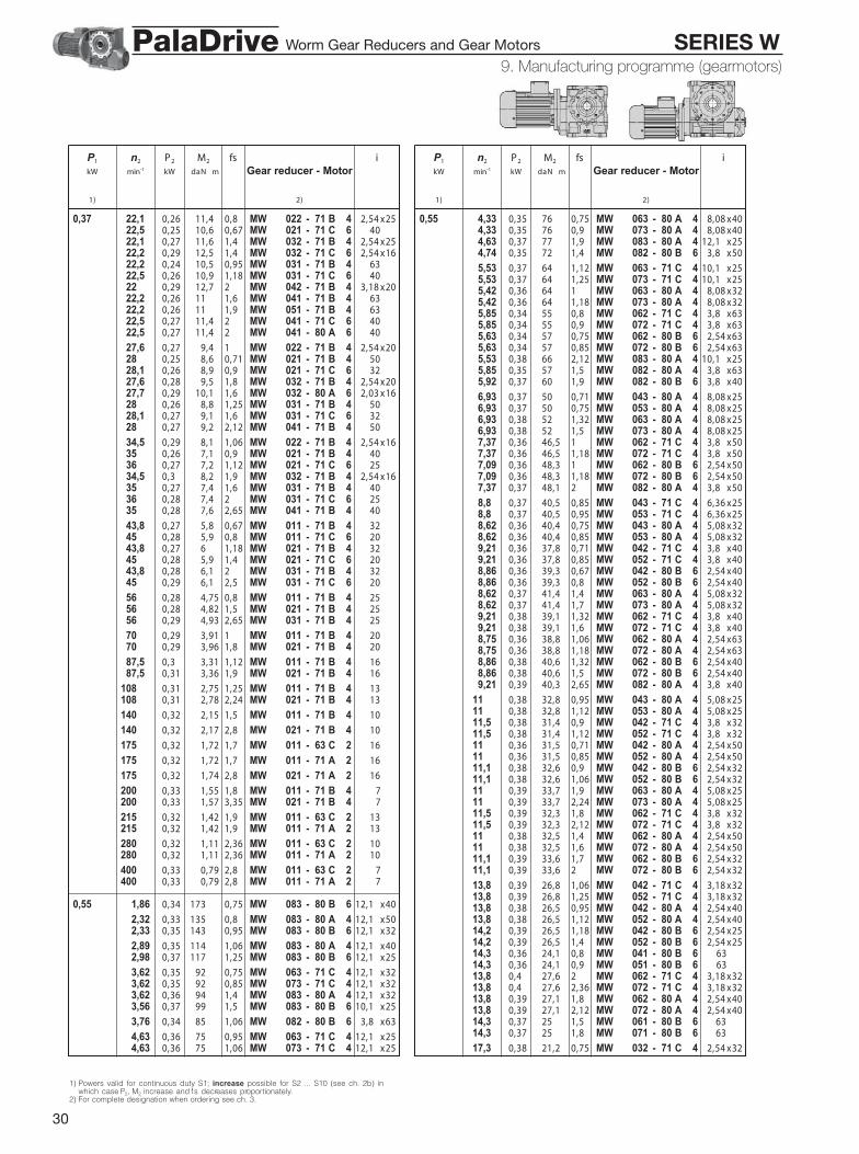
30
9 - Manufac turing programme (gearmotors )
P1 n2 P2 M2 fs ikW min-1 kW daN m Gear reducer - Motor
1) 2)
0,37 22,1 0,26 11,4 0,8 MW 022 - 71 B 4 12,54 x2522,5 0,25 10,6 0,67 MW 021 - 71 C 6 4022,1 0,27 11,6 1,4 MW 032 - 71 B 4 12,54 x2522,2 0,29 12,5 1,4 MW 032 - 71 C 6 12,54 x1622,2 0,24 10,5 0,95 MW 031 - 71 B 4 6322,5 0,26 10,9 1,18 MW 031 - 71 C 6 4022 0,29 12,7 2 MW 042 - 71 B 4 13,18 x2022,2 0,26 11 1,6 MW 041 - 71 B 4 6322,2 0,26 11 1,9 MW 051 - 71 B 4 6322,5 0,27 11,4 2 MW 041 - 71 C 6 4022,5 0,27 11,4 2 MW 041 - 80 A 6 40
27,6 0,27 9,4 1 MW 022 - 71 B 4 12,54 x2028 0,25 8,6 0,71 MW 021 - 71 B 4 5028,1 0,26 8,9 0,9 MW 021 - 71 C 6 3227,6 0,28 9,5 1,8 MW 032 - 71 B 4 12,54 x2027,7 0,29 10,1 1,6 MW 032 - 80 A 6 12,03 x1628 0,26 8,8 1,25 MW 031 - 71 B 4 5028,1 0,27 9,1 1,6 MW 031 - 71 C 6 3228 0,27 9,2 2,12 MW 041 - 71 B 4 50
34,5 0,29 8,1 1,06 MW 022 - 71 B 4 12,54 x1635 0,26 7,1 0,9 MW 021 - 71 B 4 4036 0,27 7,2 1,12 MW 021 - 71 C 6 2534,5 0,3 8,2 1,9 MW 032 - 71 B 4 12,54 x1635 0,27 7,4 1,6 MW 031 - 71 B 4 4036 0,28 7,4 2 MW 031 - 71 C 6 2535 0,28 7,6 2,65 MW 041 - 71 B 4 40
43,8 0,27 5,8 0,67 MW 011 - 71 B 4 3245 0,28 5,9 0,8 MW 011 - 71 C 6 2043,8 0,27 6 1,18 MW 021 - 71 B 4 3245 0,28 5,9 1,4 MW 021 - 71 C 6 2043,8 0,28 6,1 2 MW 031 - 71 B 4 3245 0,29 6,1 2,5 MW 031 - 71 C 6 20
56 0,28 4,75 0,8 MW 011 - 71 B 4 2556 0,28 4,82 1,5 MW 021 - 71 B 4 2556 0,29 4,93 2,65 MW 031 - 71 B 4 25
70 0,29 3,91 1 MW 011 - 71 B 4 2070 0,29 3,96 1,8 MW 021 - 71 B 4 20
87,5 0,3 3,31 1,12 MW 011 - 71 B 4 1687,5 0,31 3,36 1,9 MW 021 - 71 B 4 16
108 0,31 2,75 1,25 MW 011 - 71 B 4 13108 0,31 2,78 2,24 MW 021 - 71 B 4 13
140 0,32 2,15 1,5 MW 011 - 71 B 4 10
140 0,32 2,17 2,8 MW 021 - 71 B 4 10
175 0,32 1,72 1,7 MW 011 - 63 C 2 16
175 0,32 1,72 1,7 MW 011 - 71 A 2 16
175 0,32 1,74 2,8 MW 021 - 71 A 2 16
200 0,33 1,55 1,8 MW 011 - 71 B 4 7200 0,33 1,57 3,35 MW 021 - 71 B 4 7
215 0,32 1,42 1,9 MW 011 - 63 C 2 13215 0,32 1,42 1,9 MW 011 - 71 A 2 13
280 0,32 1,11 2,36 MW 011 - 63 C 2 10280 0,32 1,11 2,36 MW 011 - 71 A 2 10
400 0,33 0,79 2,8 MW 011 - 63 C 2 7400 0,33 0,79 2,8 MW 011 - 71 A 2 7
0,55 1,86 0,34 173 0,75 MW 083 - 80 B 6 12,1 x40
2,32 0,33 135 0,8 MW 083 - 80 A 4 12,1 x502,33 0,35 143 0,95 MW 083 - 80 B 6 12,1 x32
2,89 0,35 114 1,06 MW 083 - 80 A 4 12,1 x402,98 0,37 117 1,25 MW 083 - 80 B 6 12,1 x25
3,62 0,35 92 0,75 MW 063 - 71 C 4 12,1 x323,62 0,35 92 0,85 MW 073 - 71 C 4 12,1 x323,62 0,36 94 1,4 MW 083 - 80 A 4 12,1 x323,56 0,37 99 1,5 MW 083 - 80 B 6 10,1 x25
3,76 0,34 85 1,06 MW 082 - 80 B 6 23,8 x63
4,63 0,36 75 0,95 MW 063 - 71 C 4 12,1 x254,63 0,36 75 1,06 MW 073 - 71 C 4 12,1 x25
P1 n2 P2 M2 fs ikW min-1 kW daN m Gear reducer - Motor
1) 2)
0,55 4,33 0,35 76 0,75 MW 063 - 80 A 4 28,08 x404,33 0,35 76 0,9 MW 073 - 80 A 4 28,08 x404,63 0,37 77 1,9 MW 083 - 80 A 4 12,1 x254,74 0,35 72 1,4 MW 082 - 80 B 6 23,8 x50
5,53 0,37 64 1,12 MW 063 - 71 C 4 10,1 x255,53 0,37 64 1,25 MW 073 - 71 C 4 10,1 x255,42 0,36 64 1 MW 063 - 80 A 4 28,08 x325,42 0,36 64 1,18 MW 073 - 80 A 4 28,08 x325,85 0,34 55 0,8 MW 062 - 71 C 4 23,8 x635,85 0,34 55 0,9 MW 072 - 71 C 4 23,8 x635,63 0,34 57 0,75 MW 062 - 80 B 6 22,54 x635,63 0,34 57 0,85 MW 072 - 80 B 6 22,54 x635,53 0,38 66 2,12 MW 083 - 80 A 4 10,1 x255,85 0,35 57 1,5 MW 082 - 80 A 4 23,8 x635,92 0,37 60 1,9 MW 082 - 80 B 6 23,8 x40
6,93 0,37 50 0,71 MW 043 - 80 A 4 28,08 x256,93 0,37 50 0,75 MW 053 - 80 A 4 28,08 x256,93 0,38 52 1,32 MW 063 - 80 A 4 28,08 x256,93 0,38 52 1,5 MW 073 - 80 A 4 28,08 x257,37 0,36 46,5 1 MW 062 - 71 C 4 23,8 x507,37 0,36 46,5 1,18 MW 072 - 71 C 4 23,8 x507,09 0,36 48,3 1 MW 062 - 80 B 6 22,54 x507,09 0,36 48,3 1,18 MW 072 - 80 B 6 22,54 x507,37 0,37 48,1 2 MW 082 - 80 A 4 23,8 x50
8,8 0,37 40,5 0,85 MW 043 - 71 C 4 26,36 x258,8 0,37 40,5 0,95 MW 053 - 71 C 4 26,36 x258,62 0,36 40,4 0,75 MW 043 - 80 A 4 25,08 x328,62 0,36 40,4 0,85 MW 053 - 80 A 4 25,08 x329,21 0,36 37,8 0,71 MW 042 - 71 C 4 23,8 x409,21 0,36 37,8 0,85 MW 052 - 71 C 4 23,8 x408,86 0,36 39,3 0,67 MW 042 - 80 B 6 22,54 x408,86 0,36 39,3 0,8 MW 052 - 80 B 6 22,54 x408,62 0,37 41,4 1,4 MW 063 - 80 A 4 25,08 x328,62 0,37 41,4 1,7 MW 073 - 80 A 4 25,08 x329,21 0,38 39,1 1,32 MW 062 - 71 C 4 23,8 x409,21 0,38 39,1 1,6 MW 072 - 71 C 4 23,8 x408,75 0,36 38,8 1,06 MW 062 - 80 A 4 22,54 x638,75 0,36 38,8 1,18 MW 072 - 80 A 4 22,54 x638,86 0,38 40,6 1,32 MW 062 - 80 B 6 22,54 x408,86 0,38 40,6 1,5 MW 072 - 80 B 6 22,54 x409,21 0,39 40,3 2,65 MW 082 - 80 A 4 23,8 x40
11 0,38 32,8 0,95 MW 043 - 80 A 4 25,08 x2511 0,38 32,8 1,12 MW 053 - 80 A 4 25,08 x2511,5 0,38 31,4 0,9 MW 042 - 71 C 4 23,8 x3211,5 0,38 31,4 1,12 MW 052 - 71 C 4 23,8 x3211 0,36 31,5 0,71 MW 042 - 80 A 4 22,54 x5011 0,36 31,5 0,85 MW 052 - 80 A 4 22,54 x5011,1 0,38 32,6 0,9 MW 042 - 80 B 6 22,54 x3211,1 0,38 32,6 1,06 MW 052 - 80 B 6 22,54 x3211 0,39 33,7 1,9 MW 063 - 80 A 4 25,08 x2511 0,39 33,7 2,24 MW 073 - 80 A 4 25,08 x2511,5 0,39 32,3 1,8 MW 062 - 71 C 4 23,8 x3211,5 0,39 32,3 2,12 MW 072 - 71 C 4 23,8 x3211 0,38 32,5 1,4 MW 062 - 80 A 4 22,54 x5011 0,38 32,5 1,6 MW 072 - 80 A 4 22,54 x5011,1 0,39 33,6 1,7 MW 062 - 80 B 6 22,54 x3211,1 0,39 33,6 2 MW 072 - 80 B 6 22,54 x32
13,8 0,39 26,8 1,06 MW 042 - 71 C 4 23,18 x3213,8 0,39 26,8 1,25 MW 052 - 71 C 4 23,18 x3213,8 0,38 26,5 0,95 MW 042 - 80 A 4 22,54 x4013,8 0,38 26,5 1,12 MW 052 - 80 A 4 22,54 x4014,2 0,39 26,5 1,18 MW 042 - 80 B 6 22,54 x2514,2 0,39 26,5 1,4 MW 052 - 80 B 6 22,54 x2514,3 0,36 24,1 0,8 MW 041 - 80 B 6 6314,3 0,36 24,1 0,9 MW 051 - 80 B 6 6313,8 0,4 27,6 2 MW 062 - 71 C 4 23,18 x3213,8 0,4 27,6 2,36 MW 072 - 71 C 4 23,18 x3213,8 0,39 27,1 1,8 MW 062 - 80 A 4 22,54 x4013,8 0,39 27,1 2,12 MW 072 - 80 A 4 22,54 x4014,3 0,37 25 1,5 MW 061 - 80 B 6 2 6314,3 0,37 25 1,8 MW 071 - 80 B 6 2 63
17,3 0,38 21,2 0,75 MW 032 - 71 C 4 22,54 x32
9. Manufacturing programme (gearmotors)
1) Powers valid for continuous duty S1; increase possible for S2 ... S10 (see ch. 2b) inwhich case P2, M2 increase and fs decreases proportionately.
2) For complete designation when ordering see ch. 3.
Worm Gear Reducers and Gear Motors SERIES WPalaDrive

31
9 - Manufac turing programme (gearmotors )
P1 n2 P2 M2 fs ikW min-1 kW daN m Gear reducer - Motor
1) 2)
0,55 17,7 0,39 21,1 0,8 MW 032 - 80 B 6 22,03 x2517,6 0,4 21,8 1,4 MW 042 - 71 C 4 23,18 x2517,6 0,4 21,8 1,6 MW 052 - 71 C 4 23,18 x2517,2 0,39 21,8 1,18 MW 042 - 80 A 4 22,54 x3217,2 0,39 21,8 1,5 MW 052 - 80 A 4 22,54 x3218 0,38 20,2 1,06 MW 041 - 80 B 6 5018 0,38 20,2 1,25 MW 051 - 80 B 6 5017,6 0,41 22,3 2,65 MW 062 - 71 C 4 23,18 x2517,6 0,41 22,3 3,15 MW 072 - 71 C 4 23,18 x2517,2 0,4 22,4 2,36 MW 062 - 80 A 4 22,54 x3217,2 0,4 22,4 2,8 MW 072 - 80 A 4 22,54 x3218 0,39 20,9 2 MW 061 - 80 B 6 5018 0,39 20,9 2,36 MW 071 - 80 B 6 50
22,1 0,4 17,2 0,95 MW 032 - 71 C 4 22,54 x2521,5 0,39 17,3 0,9 MW 032 - 80 A 4 22,03 x3222,2 0,4 17,4 1,06 MW 032 - 80 B 6 22,03 x2022,5 0,38 16,2 0,8 MW 031 - 80 B 6 4022 0,44 18,9 1,32 MW 042 - 71 C 4 23,18 x2022 0,44 18,9 1,6 MW 052 - 71 C 4 23,18 x2022,1 0,41 17,7 1,6 MW 042 - 80 A 4 22,54 x2522,1 0,41 17,7 1,9 MW 052 - 80 A 4 22,54 x2522,2 0,38 16,4 1,06 MW 041 - 71 C 4 6322,2 0,38 16,4 1,25 MW 051 - 71 C 4 6322,2 0,38 16,4 1,06 MW 041 - 80 A 4 6322,2 0,38 16,4 1,25 MW 051 - 80 A 4 6322,5 0,4 16,9 1,4 MW 041 - 80 B 6 4022,5 0,4 16,9 1,6 MW 051 - 80 B 6 4022,2 0,39 16,9 2 MW 061 - 80 A 4 6322,2 0,39 16,9 2,36 MW 071 - 80 A 4 63
0,41 27,6 0,4 13,9 0,67 MW 022 - 71 C 4 22,54 x2027,6 0,41 14,2 1,18 MW 032 - 71 C 4 22,54 x2027,6 0,41 14 1,12 MW 032 - 80 A 4 22,03 x2528 0,38 13,1 0,85 MW 031 - 71 C 4 5028 0,38 13,1 0,85 MW 031 - 80 A 4 5028,1 0,4 13,5 1,06 MW 031 - 80 B 6 3227,5 0,44 15,4 1,8 MW 042 - 71 C 4 23,18 x1627,5 0,44 15,4 2,12 MW 052 - 71 C 4 23,18 x1627,6 0,44 15,3 1,6 MW 042 - 80 A 4 22,54 x2027,6 0,44 15,3 1,9 MW 052 - 80 A 4 22,54 x2028 0,4 13,7 1,4 MW 041 - 71 C 4 5028 0,4 13,7 1,7 MW 051 - 71 C 4 5028 0,4 13,7 1,4 MW 041 - 80 A 4 5028 0,4 13,7 1,7 MW 051 - 80 A 4 5028,1 0,41 13,9 1,7 MW 041 - 80 B 6 3228,1 0,41 13,9 2,12 MW 051 - 80 B 6 32
34,5 0,43 12 0,71 MW 022 - 71 C 4 22,54 x160,46 36 0,4 10,7 0,75 MW 021 - 80 B 6 25
34,5 0,44 12,2 1,32 MW 032 - 71 C 4 22,54 x1634,5 0,42 11,5 1,4 MW 032 - 80 A 4 22,03 x2035 0,4 10,9 1,06 MW 031 - 71 C 4 4035 0,4 10,9 1,06 MW 031 - 80 A 4 4036 0,41 11 1,4 MW 031 - 80 B 6 2534,5 0,45 12,4 2,12 MW 042 - 80 A 4 12,54 x1635 0,42 11,4 1,8 MW 041 - 71 C 4 4035 0,42 11,4 1,8 MW 041 - 80 A 4 40
43,8 0,41 8,9 0,8 MW 021 - 71 C 4 3245 0,42 8,8 0,9 MW 021 - 80 B 6 2043,1 0,45 9,9 1,5 MW 032 - 80 A 4 12,03 x1643,8 0,42 9,1 1,4 MW 031 - 71 C 4 3243,8 0,42 9,1 1,4 MW 031 - 80 A 4 3245 0,42 9 1,7 MW 031 - 80 B 6 2043,8 0,43 9,3 2,24 MW 041 - 80 A 4 32
56 0,42 7,2 1 MW 021 - 71 C 4 2556 0,42 7,2 1 MW 021 - 80 A 4 2556 0,43 7,3 1,8 MW 031 - 71 C 4 2556 0,43 7,3 1,8 MW 031 - 80 A 4 25
0,44 70 0,43 5,8 0,71 MW 011 - 71 C 4 2070 0,43 5,9 1,18 MW 021 - 71 C 4 2070 0,43 5,9 1,18 MW 021 - 80 A 4 2070 0,44 6 2,12 MW 031 - 71 C 4 2070 0,44 6 2,12 MW 031 - 80 A 4 2087,5 0,45 4,93 0,75 MW 011 - 71 C 4 16
P1 n2 P2 M2 fs ikW min-1 kW daN m Gear reducer - Motor
1) 2)
0,55 87,5 0,46 4,99 1,32 MW 021 - 71 C 4 1687,5 0,46 4,99 1,32 MW 021 - 80 A 4 1687,5 0,46 5,1 2,36 MW 031 - 71 C 4 1687,5 0,46 5,1 2,36 MW 031 - 80 A 4 16
108 0,46 4,09 0,85 MW 011 - 71 C 4 13108 0,47 4,13 1,5 MW 021 - 71 C 4 13108 0,47 4,13 1,5 MW 021 - 80 A 4 13108 0,47 4,18 2,65 MW 031 - 71 C 4 13108 0,47 4,18 2,65 MW 031 - 80 A 4 13
140 0,47 3,19 1 MW 011 - 71 C 4 10140 0,47 3,23 1,8 MW 021 - 71 C 4 10140 0,47 3,23 1,8 MW 021 - 80 A 4 10
175 0,47 2,56 1,12 MW 011 - 71 B 2 16175 0,47 2,58 2 MW 021 - 71 B 2 16
200 0,48 2,31 1,25 MW 011 - 71 C 4 7200 0,49 2,33 2,24 MW 021 - 71 C 4 7200 0,49 2,33 2,24 MW 021 - 80 A 4 7
215 0,48 2,11 1,32 MW 011 - 71 B 2 13215 0,48 2,13 2,24 MW 021 - 71 B 2 13
280 0,48 1,64 1,6 MW 011 - 71 B 2 10280 0,49 1,66 2,8 MW 021 - 71 B 2 10
400 0,49 1,18 1,9 MW 011 - 71 B 2 7400 0,5 1,19 3,35 MW 021 - 71 B 2 7
0,75 1,5 0,45 286 0,75 MW 093 - 90 S 6 12 x50
1,87 0,46 236 1 MW 093 - 90 S 6 12 x40
2,33 0,48 195 0,71 MW 083 - 80 C 6 12,1 x322,34 0,48 198 1,32 MW 093 - 90 S 6 12 x32
2,89 0,47 155 0,8 MW 083 - 80 B 4 12,1 x402,98 0,5 160 0,95 MW 083 - 80 C 6 12,1 x252,88 0,49 162 1,5 MW 093 - 90 S 6 29,75 x322,88 0,49 162 1,7 MW 103 - 90 S 6 29,75 x32
3,62 0,49 128 1,06 MW 083 - 80 B 4 12,1 x323,55 0,48 130 1,6 MW 093 - 90 S 6 26,34 x403,55 0,48 130 1,9 MW 103 - 90 S 6 26,34 x403,7 0,47 121 1,32 MW 092 - 90 S 6 23,86 x633,7 0,47 121 1,6 MW 102 - 90 S 6 23,86 x63
3,76 0,46 116 0,75 MW 082 - 80 C 6 23,8 x63
4,46 0,5 107 0,75 MW 073 - 80 C 6 28,08 x254,63 0,51 105 1,4 MW 083 - 80 B 4 12,1 x254,74 0,48 98 1 MW 082 - 80 C 6 23,8 x504,67 0,5 102 1,8 MW 092 - 90 S 6 23,86 x504,67 0,5 102 2,12 MW 102 - 90 S 6 23,86 x50
5,42 0,49 87 0,75 MW 063 - 80 B 4 28,08 x325,42 0,49 87 0,85 MW 073 - 80 B 4 28,08 x325,53 0,52 89 1,6 MW 083 - 80 B 4 10,1 x255,85 0,48 78 1,06 MW 082 - 80 B 4 23,8 x635,92 0,51 82 1,4 MW 082 - 80 C 6 23,8 x405,83 0,51 84 2,36 MW 092 - 90 S 6 23,86 x40
6,93 0,51 71 0,95 MW 063 - 80 B 4 28,08 x256,93 0,51 71 1,12 MW 073 - 80 B 4 28,08 x257,09 0,49 66 0,71 MW 062 - 80 C 6 22,54 x507,09 0,49 66 0,85 MW 072 - 80 C 6 22,54 x506,88 0,51 71 1,8 MW 083 - 80 B 4 26,36 x327,37 0,51 66 1,4 MW 082 - 80 B 4 23,8 x507,4 0,52 68 1,9 MW 082 - 80 C 6 23,8 x32
8,62 0,51 57 1,06 MW 063 - 80 B 4 25,08 x328,62 0,51 57 1,25 MW 073 - 80 B 4 25,08 x328,75 0,48 53 0,75 MW 062 - 80 B 4 22,54 x638,75 0,48 53 0,9 MW 072 - 80 B 4 22,54 x638,86 0,51 55 0,95 MW 062 - 80 C 6 22,54 x408,86 0,51 55 1,12 MW 072 - 80 C 6 22,54 x409,21 0,53 55 2 MW 082 - 80 B 4 23,8 x40
11 0,52 44,8 0,71 MW 043 - 80 B 4 25,08 x2511 0,52 44,8 0,85 MW 053 - 80 B 4 25,08 x2511,1 0,52 44,4 0,67 MW 042 - 80 C 6 22,54 x3211,1 0,52 44,4 0,75 MW 052 - 80 C 6 22,54 x3211 0,53 45,9 1,4 MW 063 - 80 B 4 25,08 x25
9. Manufacturing programme (gearmotors)
Values in red state nominal thermal power PtN (ambient temperature 40 °C, continuousduty, see ch. 4).1) Powers valid for continuous duty S1; increase possible for S2 ... S10 (see ch. 2b) in
which case P2, M2 increase and fs decreases proportionately.2) For complete designation when ordering see ch. 3.
Worm Gear Reducers and Gear Motors SERIES WPalaDrive
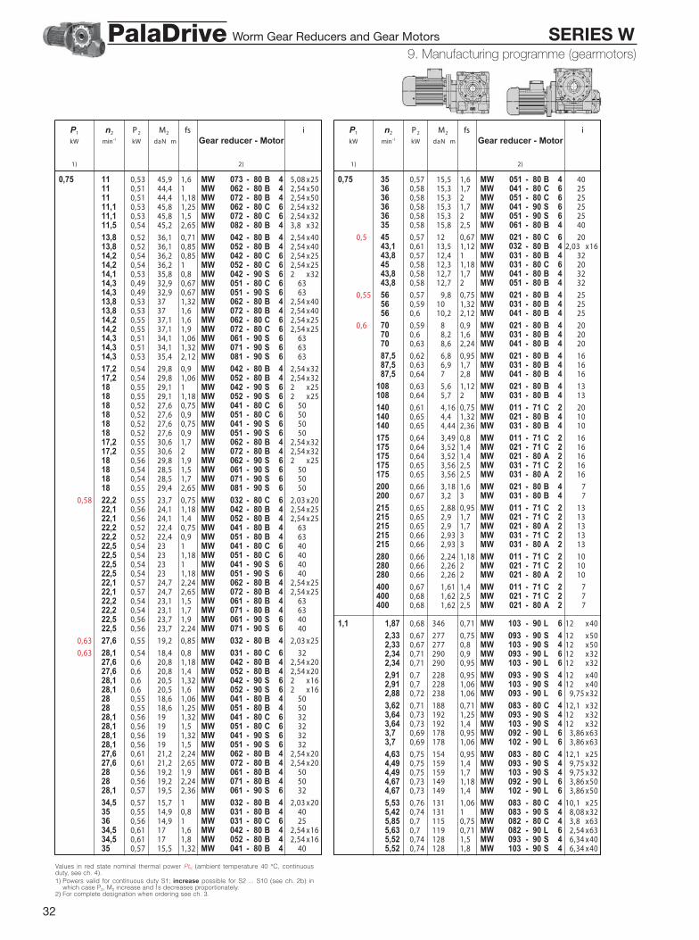
32
9 - Manufac turing programme (gearmotors )
P1 n2 P2 M2 fs ikW min-1 kW daN m Gear reducer - Motor
1) 2)
0,75 11 0,53 45,9 1,6 MW 073 - 80 B 4 25,08 x2511 0,51 44,4 1 MW 062 - 80 B 4 22,54 x5011 0,51 44,4 1,18 MW 072 - 80 B 4 22,54 x5011,1 0,53 45,8 1,25 MW 062 - 80 C 6 22,54 x3211,1 0,53 45,8 1,5 MW 072 - 80 C 6 22,54 x3211,5 0,54 45,2 2,65 MW 082 - 80 B 4 23,8 x32
13,8 0,52 36,1 0,71 MW 042 - 80 B 4 22,54 x4013,8 0,52 36,1 0,85 MW 052 - 80 B 4 22,54 x4014,2 0,54 36,2 0,85 MW 042 - 80 C 6 22,54 x2514,2 0,54 36,2 1 MW 052 - 80 C 6 22,54 x2514,1 0,53 35,8 0,8 MW 042 - 90 S 6 22 x3214,3 0,49 32,9 0,67 MW 051 - 80 C 6 6314,3 0,49 32,9 0,67 MW 051 - 90 S 6 6313,8 0,53 37 1,32 MW 062 - 80 B 4 22,54 x4013,8 0,53 37 1,6 MW 072 - 80 B 4 22,54 x4014,2 0,55 37,1 1,6 MW 062 - 80 C 6 22,54 x2514,2 0,55 37,1 1,9 MW 072 - 80 C 6 22,54 x2514,3 0,51 34,1 1,06 MW 061 - 90 S 6 6314,3 0,51 34,1 1,32 MW 071 - 90 S 6 6314,3 0,53 35,4 2,12 MW 081 - 90 S 6 63
17,2 0,54 29,8 0,9 MW 042 - 80 B 4 22,54 x3217,2 0,54 29,8 1,06 MW 052 - 80 B 4 22,54 x3218 0,55 29,1 1 MW 042 - 90 S 6 22 x2518 0,55 29,1 1,18 MW 052 - 90 S 6 22 x2518 0,52 27,6 0,75 MW 041 - 80 C 6 5018 0,52 27,6 0,9 MW 051 - 80 C 6 5018 0,52 27,6 0,75 MW 041 - 90 S 6 5018 0,52 27,6 0,9 MW 051 - 90 S 6 5017,2 0,55 30,6 1,7 MW 062 - 80 B 4 22,54 x3217,2 0,55 30,6 2 MW 072 - 80 B 4 22,54 x3218 0,56 29,8 1,9 MW 062 - 90 S 6 22 x2518 0,54 28,5 1,5 MW 061 - 90 S 6 5018 0,54 28,5 1,7 MW 071 - 90 S 6 5018 0,55 29,4 2,65 MW 081 - 90 S 6 50
0,58 22,2 0,55 23,7 0,75 MW 032 - 80 C 6 22,03 x2022,1 0,56 24,1 1,18 MW 042 - 80 B 4 22,54 x2522,1 0,56 24,1 1,4 MW 052 - 80 B 4 22,54 x2522,2 0,52 22,4 0,75 MW 041 - 80 B 4 6322,2 0,52 22,4 0,9 MW 051 - 80 B 4 6322,5 0,54 23 1 MW 041 - 80 C 6 4022,5 0,54 23 1,18 MW 051 - 80 C 6 4022,5 0,54 23 1 MW 041 - 90 S 6 4022,5 0,54 23 1,18 MW 051 - 90 S 6 4022,1 0,57 24,7 2,24 MW 062 - 80 B 4 22,54 x2522,1 0,57 24,7 2,65 MW 072 - 80 B 4 22,54 x2522,2 0,54 23,1 1,5 MW 061 - 80 B 4 6322,2 0,54 23,1 1,7 MW 071 - 80 B 4 6322,5 0,56 23,7 1,9 MW 061 - 90 S 6 4022,5 0,56 23,7 2,24 MW 071 - 90 S 6 40
0,63 27,6 0,55 19,2 0,85 MW 032 - 80 B 4 22,03 x25
0,63 28,1 0,54 18,4 0,8 MW 031 - 80 C 6 3227,6 0,6 20,8 1,18 MW 042 - 80 B 4 22,54 x2027,6 0,6 20,8 1,4 MW 052 - 80 B 4 22,54 x2028,1 0,6 20,5 1,32 MW 042 - 90 S 6 22 x1628,1 0,6 20,5 1,6 MW 052 - 90 S 6 22 x1628 0,55 18,6 1,06 MW 041 - 80 B 4 5028 0,55 18,6 1,25 MW 051 - 80 B 4 5028,1 0,56 19 1,32 MW 041 - 80 C 6 3228,1 0,56 19 1,5 MW 051 - 80 C 6 3228,1 0,56 19 1,32 MW 041 - 90 S 6 3228,1 0,56 19 1,5 MW 051 - 90 S 6 3227,6 0,61 21,2 2,24 MW 062 - 80 B 4 22,54 x2027,6 0,61 21,2 2,65 MW 072 - 80 B 4 22,54 x2028 0,56 19,2 1,9 MW 061 - 80 B 4 5028 0,56 19,2 2,24 MW 071 - 80 B 4 5028,1 0,57 19,5 2,36 MW 061 - 90 S 6 32
34,5 0,57 15,7 1 MW 032 - 80 B 4 22,03 x2035 0,55 14,9 0,8 MW 031 - 80 B 4 4036 0,56 14,9 1 MW 031 - 80 C 6 2534,5 0,61 17 1,6 MW 042 - 80 B 4 22,54 x1634,5 0,61 17 1,8 MW 052 - 80 B 4 22,54 x1635 0,57 15,5 1,32 MW 041 - 80 B 4 40
P1 n2 P2 M2 fs ikW min-1 kW daN m Gear reducer - Motor
1) 2)
0,75 35 0,57 15,5 1,6 MW 051 - 80 B 4 4036 0,58 15,3 1,7 MW 041 - 80 C 6 2536 0,58 15,3 2 MW 051 - 80 C 6 2536 0,58 15,3 1,7 MW 041 - 90 S 6 2536 0,58 15,3 2 MW 051 - 90 S 6 2535 0,58 15,8 2,5 MW 061 - 80 B 4 40
0,5 45 0,57 12 0,67 MW 021032
- 80 C 6 2043,1 0,61 13,5 1,12 MW - 80 B 4 2,03 x1643,8 0,57 12,4 1 MW 031 - 80 B 4 3245 0,58 12,3 1,18 MW 031 - 80 C 6 2043,8 0,58 12,7 1,7 MW 041 - 80 B 4 3243,8 0,58 12,7 2 MW 051 - 80 B 4 32
0,55 56 0,57 9,8 0,75 MW 021 - 80 B 4 2556 0,59 10 1,32 MW 031 - 80 B 4 2556 0,6 10,2 2,12 MW 041 - 80 B 4 25
0,6 70 0,59 8 0,9 MW 021 - 80 B 4 2070 0,6 8,2 1,6 MW 031 - 80 B 4 2070 0,63 8,6 2,24 MW 041 - 80 B 4 20
87,5 0,62 6,8 0,95 MW 021 - 80 B 4 1687,5 0,63 6,9 1,7 MW 031 - 80 B 4 1687,5 0,64 7 2,8 MW 041 - 80 B 4 16
108 0,63 5,6 1,12 MW 021 - 80 B 4 13108 0,64 5,7 2 MW 031 - 80 B 4 13
140 0,61 4,16 0,75 MW 011 - 71 C 2 20140 0,65 4,4 1,32 MW 021 - 80 B 4 10140 0,65 4,44 2,36 MW 031 - 80 B 4 10
175 0,64 3,49 0,8 MW 011 - 71 C 2 16175 0,64 3,52 1,4 MW 021 - 71 C 2 16175 0,64 3,52 1,4 MW 021 - 80 A 2 16175 0,65 3,56 2,5 MW 031 - 71 C 2 16175 0,65 3,56 2,5 MW 031 - 80 A 2 16
200 0,66 3,18 1,6 MW 021 - 80 B 4 7200 0,67 3,2 3 MW 031 - 80 B 4 7
215 0,65 2,88 0,95 MW 011 - 71 C 2 13215 0,65 2,9 1,7 MW 021 - 71 C 2 13215 0,65 2,9 1,7 MW 021 - 80 A 2 13215 0,66 2,93 3 MW 031 - 71 C 2 13215 0,66 2,93 3 MW 031 - 80 A 2 13
280 0,66 2,24 1,18 MW 011 - 71 C 2 10280 0,66 2,26 2 MW 021 - 71 C 2 10280 0,66 2,26 2 MW 021 - 80 A 2 10
400 0,67 1,61 1,4 MW 011 - 71 C 2 7400 0,68 1,62 2,5 MW 021 - 71 C 2 7400 0,68 1,62 2,5 MW 021 - 80 A 2 7
1,1 1,87 0,68 346 0,71 MW 103 - 90 L 6 12 x40
2,33 0,67 277 0,75 MW 093 - 90 S 4 12 x502,33 0,67 277 0,8 MW 103 - 90 S 4 12 x502,34 0,71 290 0,9 MW 093 - 90 L 6 12 x322,34 0,71 290 0,95 MW 103 - 90 L 6 12 x32
2,91 0,7 228 0,95 MW 093 - 90 S 4 12 x402,91 0,7 228 1,06 MW 103 - 90 S 4 12 x402,88 0,72 238 1,06 MW 093 - 90 L 6 29,75 x32
3,62 0,71 188 0,71 MW 083 - 80 C 4 12,1 x323,64 0,73 192 1,25 MW 093 - 90 S 4 12 x323,64 0,73 192 1,4 MW 103 - 90 S 4 12 x323,7 0,69 178 0,95 MW 092 - 90 L 6 23,86 x633,7 0,69 178 1,06 MW 102 - 90 L 6 23,86 x63
4,63 0,75 154 0,95 MW 083 - 80 C 4 12,1 x254,49 0,75 159 1,4 MW 093 - 90 S 4 29,75 x324,49 0,75 159 1,7 MW 103 - 90 S 4 29,75 x324,67 0,73 149 1,18 MW 092 - 90 L 6 23,86 x504,67 0,73 149 1,4 MW 102 - 90 L 6 23,86 x50
5,53 0,76 131 1,06 MW 083 - 80 C 4 10,1 x255,42 0,74 131 1 MW 083 - 90 S 4 28,08 x325,85 0,7 115 0,75 MW 082 - 80 C 4 23,8 x635,63 0,7 119 0,71 MW 082 - 90 L 6 22,54 x635,52 0,74 128 1,5 MW 093 - 90 S 4 26,34 x405,52 0,74 128 1,8 MW 103 - 90 S 4 26,34 x40
9. Manufacturing programme (gearmotors)
Values in red state nominal thermal power PtN (ambient temperature 40 °C, continuousduty, see ch. 4).1) Powers valid for continuous duty S1; increase possible for S2 ... S10 (see ch. 2b) in
which case P2, M2 increase and fs decreases proportionately.2) For complete designation when ordering see ch. 3.
Worm Gear Reducers and Gear Motors SERIES WPalaDrive

33
Values in red state nominal thermal power PtN (ambient temperature 40 °C, continuousduty, see ch. 4).1) Powers valid for continuous duty S1; increase possible for S2 ... S10 (see ch. 2b) in
which case P2, M2 increase and fs decreases proportionately.2) For complete designation when ordering see ch. 3.
9 - Manufac turing programme (gearmotors )
P1 n2 P2 M2 fs ikW min-1 kW daN m Gear reducer - Motor
1) 2)
1,1 5,76 0,73 120 1,25 MW 092 - 90 S 4 23,86 x635,76 0,73 120 1,5 MW 102 - 90 S 4 23,86 x635,83 0,75 123 1,6 MW 092 - 90 L 6 23,86 x405,83 0,75 123 1,9 MW 102 - 90 L 6 23,86 x40
0,92 6,93 0,75 104 0,75 MW 073 - 80 C 4 28,08 x256,93 0,77 106 1,32 MW 083 - 90 S 4 28,08 x257,37 0,74 96 1 MW 082 - 80 C 4 23,8 x507,09 0,74 100 0,95 MW 082 - 90 L 6 22,54 x506,9 0,77 107 2 MW 093 - 90 S 4 26,34 x327,26 0,76 100 1,6 MW 092 - 90 S 4 23,86 x507,26 0,76 100 1,9 MW 102 - 90 S 4 23,86 x507,2 0,77 102 1,8 MW 092 - 90 L 6 23,13 x40
8,62 0,75 83 0,71 MW 063 - 80 C 4 25,08 x328,62 0,75 83 0,85 MW 073 - 80 C 4 25,08 x329 0,73 78 0,71 MW 072 - 90 L 6 22 x508,8 0,79 85 1,6 MW 083 - 80 C 4 26,36 x258,62 0,77 85 1,5 MW 083 - 90 S 4 25,08 x329,21 0,78 81 1,32 MW 082 - 80 C 4 23,8 x408,75 0,74 80 1 MW 082 - 90 S 4 22,54 x638,86 0,78 84 1,25 MW 082 - 90 L 6 22,54 x409,07 0,79 83 2,24 MW 092 - 90 S 4 23,86 x40
11 0,78 67 0,95 MW 063 - 80 C 4 25,08 x2511 0,78 67 1,12 MW 073 - 80 C 4 25,08 x2511 0,75 65 0,71 MW 062 - 80 C 4 22,54 x5011 0,75 65 0,8 MW 072 - 80 C 4 22,54 x5011,1 0,73 63 0,71 MW 072 - 90 S 4 22 x6311,3 0,77 65 0,8 MW 062 - 90 L 6 22 x4011,3 0,77 65 0,9 MW 072 - 90 L 6 22 x4011 0,8 69 1,9 MW 083 - 90 S 4 25,08 x2511,5 0,8 66 1,8 MW 082 - 80 C 4 23,8 x3211 0,78 67 1,32 MW 082 - 90 S 4 22,54 x5011,1 0,8 69 1,7 MW 082 - 90 L 6 22,54 x32
13,8 0,84 58 0,9 MW 062 - 80 C 4 25,08 x2013,8 0,84 58 1,06 MW 073 - 80 C 4 25,08 x2013,8 0,78 54 0,9 MW 062 - 80 C 4 22,54 x4013,8 0,78 54 1,06 MW 072 - 80 C 4 22,54 x4014 0,77 52 0,8 MW 062 - 90 S 4 22 x5014 0,77 52 1 MW 072 - 90 S 4 22 x5014,1 0,8 54 1 MW 062 - 90 L 6 22 x3214,1 0,8 54 1,18 MW 072 - 90 L 6 22 x3214,3 0,75 50 0,75 MW 061 - 90 L 6 6314,3 0,75 50 0,9 MW 071 - 90 L 6 6313,8 0,86 60 1,9 MW 083 - 90 S 4 25,08 x2013,8 0,81 56 2 MW 082 - 80 C 4 23,18 x3213,8 0,81 56 1,8 MW 082 - 90 S 4 22,54 x4014,2 0,83 56 2,24 MW 082 - 90 L 6 22,54 x2514,3 0,78 52 1,4 MW 081 - 90 L 6 63
0,8 17,2 0,79 43,7 0,71 MW 052 - 80 C 4 22,54 x320,82 18 0,8 42,6 0,71 MW 042 - 90 L 6 22 x250,82 18 0,8 42,6 0,85 MW 052 - 90 L 6 22 x25
17,2 0,81 44,8 1,18 MW 062 - 80 C 4 22,54 x3217,2 0,81 44,8 1,4 MW 072 - 80 C 4 22,54 x3217,5 0,8 43,6 1,06 MW 062 - 90 S 4 22 x4017,5 0,8 43,6 1,32 MW 072 - 90 S 4 22 x4018 0,82 43,7 1,32 MW 062 - 90 L 6 22 x2518 0,82 43,7 1,6 MW 072 - 90 L 6 22 x2518 0,79 41,7 1 MW 061 - 90 L 6 5018 0,79 41,7 1,18 MW 071 - 90 L 6 5017,2 0,83 45,9 2,36 MW 082 - 90 S 4 22,54 x3218 0,81 43,2 1,8 MW 081 - 90 L 6 50
0,88 22,1 0,82 35,4 0,8 MW 042 - 80 C 4 22,54 x250,88 22,1 0,82 35,4 0,95 MW 052 - 80 C 4 22,54 x250,87 21,9 0,8 35,1 0,75 MW 042 - 90 S 4 22 x320,87 21,9 0,8 35,1 0,85 MW 052 - 90 S 4 22 x320,88 22,5 0,8 33,8 0,8 MW 051 - 90 L 6 40
22,1 0,84 36,2 1,5 MW 062 - 80 C 4 22,54 x2522,1 0,84 36,2 1,8 MW 072 - 80 C 4 22,54 x2521,9 0,83 36,1 1,4 MW 062 - 90 S 4 22 x3221,9 0,83 36,1 1,6 MW 072 - 90 S 4 22 x3222,2 0,79 33,8 1 MW 061 - 80 C 4 6322,2 0,79 33,8 1,18 MW 071 - 80 C 4 6322,2 0,79 33,8 1 MW 061 - 90 S 4 63
P1 n2 P2 M2 fs ikW min-1 kW daN m Gear reducer - Motor
1) 2)
1,1 22,2 0,79 33,8 1,18 MW 071 - 90 S 4 6322,5 0,82 34,7 1,32 MW 061 - 90 L 6 4022,5 0,82 34,7 1,5 MW 071 - 90 L 6 4022,1 0,86 37,2 3 MW 082 - 90 S 4 22,54 x2522,2 0,82 35 1,9 MW 081 - 90 S 4 63
27,6 0,88 30,6 0,8 MW 042 - 80 C 4 22,54 x2027,6 0,88 30,6 0,95 MW 052 - 80 C 4 22,54 x2028 0,83 28,4 0,95 MW 042 - 90 S 4 22 x2528 0,83 28,4 1,12 MW 052 - 90 S 4 22 x2528,1 0,89 30,1 0,9 MW 042 - 90 L 6 22 x1628 0,8 27,3 0,71 MW 041 - 80 C 4 5028 0,8 27,3 0,85 MW 051 - 80 C 4 5028 0,8 27,3 0,71 MW 041 - 90 S 4 5028 0,8 27,3 0,85 MW 051 - 90 S 4 5028,1 0,82 27,8 0,85 MW 041 - 90 L 6 3228,1 0,82 27,8 1,06 MW 051 - 90 L 6 3227,6 0,9 31 1,5 MW 062 - 80 C 4 22,54 x2027,6 0,9 31 1,8 MW 072 - 80 C 4 22,54 x2028 0,85 29,1 1,8 MW 062 - 90 S 4 22 x2528 0,85 29,1 2,12 MW 072 - 90 S 4 22 x2528 0,82 28,1 1,32 MW 061 - 80 C 4 5028 0,82 28,1 1,6 MW 071 - 80 C 4 5028 0,82 28,1 1,32 MW 061 - 90 S 4 5028 0,82 28,1 1,6 MW 071 - 90 S 4 5028,1 0,84 28,6 1,6 MW 061 - 90 L 6 3228,1 0,84 28,6 1,9 MW 071 - 90 L 6 32
0,69 34,5 0,83 23,1 0,71 MW 032 - 80 C 4 22,03 x200,69 36 0,83 21,9 0,67 MW 031 - 90 L 6 25
34,5 0,9 24,9 1,06 MW 042 - 80 C 4 22,54 x1634,5 0,9 24,9 1,25 MW 052 - 80 C 4 22,54 x1635 0,89 24,4 1 MW 042 - 90 S 4 22 x2035 0,89 24,4 1,18 MW 052 - 90 S 4 22 x2035 0,83 22,7 0,9 MW 041 - 80 C 4 4035 0,83 22,7 1,06 MW 051 - 80 C 4 4035 0,83 22,7 0,9 MW 041 - 90 S 4 4035 0,83 22,7 1,06 MW 051 - 90 S 4 4036 0,85 22,5 1,12 MW 041 - 90 L 6 2536 0,85 22,5 1,32 MW 051 - 90 L 6 2534,5 0,91 25,3 2 MW 062 - 80 C 4 22,54 x1634,5 0,91 25,3 2,36 MW 072 - 80 C 4 22,54 x1635 0,91 24,7 1,8 MW 062 - 90 S 4 22 x2035 0,91 24,7 2,12 MW 072 - 90 S 4 22 x2035 0,85 23,2 1,7 MW 061 - 80 C 4 4035 0,85 23,2 2 MW 071 - 80 C 4 4035 0,85 23,2 1,7 MW 061 - 90 S 4 4035 0,85 23,2 2 MW 071 - 90 S 4 4036 0,87 23 2,12 MW 061 - 90 L 6 25
0,88 43,1 0,89 19,8 0,75 MW 032 - 80 C 4 22,03 x160,76 43,8 0,83 18,2 0,67 MW 031 - 80 C 4 320,75 45 0,85 18 0,85 MW 031 - 90 L 6 20
43,8 0,91 19,8 1,25 MW 042 - 90 S 4 22 x1643,8 0,91 19,8 1,5 MW 052 - 90 S 4 22 x1643,8 0,85 18,6 1,12 MW 041 - 80 C 4 3243,8 0,85 18,6 1,32 MW 051 - 80 C 4 3243,8 0,85 18,6 1,12 MW 041 - 90 S 4 3243,8 0,85 18,6 1,32 MW 051 - 90 S 4 3245 0,9 19,2 1,4 MW 051 - 90 L 6 2043,8 0,92 20,1 2,36 MW 062 - 90 S 4 22 x1643,8 0,92 20,1 2,8 MW 072 - 90 S 4 22 x1643,8 0,87 19,1 2,12 MW 061 - 80 C 4 3243,8 0,87 19,1 2,5 MW 071 - 80 C 4 3243,8 0,87 19,1 2,12 MW 061 - 90 S 4 3243,8 0,87 19,1 2,5 MW 071 - 90 S 4 32
0,84 56 0,86 14,7 0,9 MW 031 - 80 C 4 250,84 56 0,86 14,7 0,9 MW 031 - 90 S 4 25
56 0,88 15 1,5 MW 041 - 80 C 4 2556 0,88 15 1,7 MW 051 - 80 C 4 2556 0,88 15 1,5 MW 041 - 90 S 4 2556 0,88 15 1,7 MW 051 - 90 S 4 2556 0,9 15,3 2,8 MW 061 - 90 S 4 2556 0,9 15,3 3,35 MW 071 - 90 S 4 25
0,92 70 0,88 12 1,06 MW 031 - 80 C 4 20
9. Manufacturing programme (gearmotors)Worm Gear Reducers and Gear Motors SERIES WPalaDrive

34
Values in red state nominal thermal power PtN (ambient temperature 40 °C, continuousduty, see ch. 4).1) Powers valid for continuous duty S1; increase possible for S2 ... S10 (see ch. 2b) in
which case P2, M2 increase and fs decreases proportionately.2) For complete designation when ordering see ch. 3.* Mounting position B5R (see table ch. 2b).
9 - Manufac turing programme (gear motors )
P1 n2 P2 M2 fs ikW min-1 kW daN m Gear reducer - Motor
1) 2)
1,1 0,92 70 0,88 12 1,06 MW 031 - 90 S 4 2070 0,93 12,7 1,5 MW 041 - 80 C 4 2070 0,93 12,7 1,8 MW 051 - 80 C 4 2070 0,93 12,7 1,5 MW 041 - 90 S 4 2070 0,93 12,7 1,8 MW 051 - 90 S 4 2069,2 0,93 12,9 1,7 MW 041 - 90 L 6 1369,2 0,93 12,9 2 MW 051 - 90 L 6 13
0,77 87,5 0,91 10 0,67 MW 021 - 80 C 4 1687,5 0,93 10,1 1,18 MW 031 - 80 C 4 1687,5 0,93 10,1 1,18 MW 031 - 90 S 4 1687,5 0,94 10,3 1,9 MW 041 - 80 C 4 1687,5 0,94 10,3 1,9 MW 041 - 90 S 4 16
0,84 108 0,93 8,3 0,75 MW 021 - 80 C 4 13108 0,94 8,4 1,32 MW 031 - 80 C 4 13108 0,94 8,4 1,32 MW 031 - 90 S 4 13108 0,95 8,5 2,24 MW 041 - 90 S 4 13
0,93 140 0,95 6,5 0,9 MW 021 - 80 C 4 10140 0,96 6,5 1,6 MW 031 - 80 C 4 10140 0,96 6,5 1,6 MW 031 - 90 S 4 10140 0,98 6,7 2,8 MW 041 - 90 S 4 10
175 0,95 5,2 0,95 MW 021 - 80 B 2 16175 0,96 5,2 1,7 MW 031 - 80 B 2 16175 0,97 5,3 2,8 MW 041 - 80 B 2 16
200 0,98 4,66 1,12 MW 021 - 80 C 4 7200 0,98 4,69 2 MW 031 - 80 C 4 7200 0,98 4,69 2 MW 031 - 90 S 4 7
215 0,96 4,25 1,12 MW 021 - 80 B 2 13215 0,97 4,29 2 MW 031 - 80 B 2 13
280 0,97 3,31 1,4 MW 021 - 80 B 2 10280 0,98 3,34 2,36 MW 031 - 80 B 2 10
400 0,99 2,37 1,7 MW 021 - 80 B 2 7400 1 2,39 3 MW 031 - 80 B 2 7
1,5 2,91 0,95 311 0,71 MW 093 - 90 L 4 12 x402,91 0,95 311 0,8 MW 103 - 90 L 4 12 x40
3,64 1 262 0,9 MW 093 - 90 L 4 12 x323,64 1 262 1,06 MW 103 - 90 L 4 12 x323,7 0,94 243 0,67 MW 092 - 90 LC 6 23,86 x633,7 0,94 243 0,8 MW 102 - 90 LC 6 23,86 x633,57 0,98 261 1,25 MW 112 -100 LA 6 24 x633,57 0,98 261 1,4 MW 122 -100 LA 6 24 x63
4,49 1,02 216 1,06 MW 093 - 90 L 4 29,75 x324,49 1,02 216 1,25 MW 103 - 90 L 4 29,75 x324,57 0,97 202 0,8 MW 092 -100 LA 6 23,13 x634,57 0,97 202 0,9 MW 102 -100 LA 6 23,13 x634,67 1 204 0,9 MW 092 - 90 LC 6 23,86 x504,67 1 204 1,06 MW 102 - 90 LC 6 23,86 x504,5 1,03 218 1,6 MW 112 -100 LA 6 24 x504,5 1,03 218 1,9 MW 122 -100 LA 6 24 x50
5,42 1,01 178 0,75 MW 083 - 90 L 4 28,08 x325,52 1,01 174 1,12 MW 093 - 90 L 4 26,34 x405,52 1,01 174 1,32 MW 103 - 90 L 4 26,34 x405,47 1,03 180 1,25 MW 093 -100 LA 6 25,15 x325,76 0,99 164 0,95 MW 092 - 90 L 4 23,86 x635,76 0,99 164 1,06 MW 102 - 90 L 4 23,86 x635,76 1,02 169 1,06 MW 092 -100 LA 6 23,13 x505,76 1,02 169 1,18 MW 102 -100 LA 6 23,13 x505,83 1,03 168 1,18 MW 092 - 90 LC 6 23,86 x405,83 1,03 168 1,4 MW 102 - 90 LC 6 23,86 x405,63 1,07 181 2,24 MW 112 -100 LA 6 24 x405,63 1,07 181 2,65 MW 122 -100 LA 6 24 x40
6,93 1,05 145 0,95 MW 083 - 90 L 4 28,08 x257,37 1,01 131 0,71 MW 082 - 90 L* 4 23,8 x507,09 1,01 136 0,71 MW 082 - 90 LC 6 22,54 x506,9 1,06 146 1,5 MW 093 - 90 L 4 26,34 x326,9 1,06 146 1,7 MW 103 - 90 L 4 26,34 x327,26 1,04 137 1,18 MW 092 - 90 L 4 23,86 x507,26 1,04 137 1,4 MW 102 - 90 L 4 23,86 x507,2 1,05 139 1,32 MW 092 -100 LA 6 23,13 x407,2 1,05 139 1,6 MW 102 -100 LA 6 23,13 x40
P1 n2 P2 M2 fs ikW min-1 kW daN m Gear reducer - Motor
1) 2)
1,5 7,2 1,05 139 1,32 MW 092 - 90 LC 6 23,13 x407,2 1,05 139 1,6 MW 102 - 90 LC 6 23,13 x407,09 1,09 146 2,65 MW 112 -100 LA 6 23,17 x40
8,62 1,05 116 1,06 MW 083 - 90 L 4 25,08 x329,21 1,06 110 1 MW 082 - 90 L* 4 23,8 x408,75 1 110 0,75 MW 082 - 90 L 4 22,54 x639 1,04 110 0,85 MW 082 -100 LA 6 22 x508,83 1,15 125 1,8 MW 103 - 90 L 4 26,34 x259,07 1,07 113 1,6 MW 092 - 90 L 4 23,86 x409,07 1,07 113 1,9 MW 102 - 90 L 4 23,86 x409 1,09 116 1,8 MW 092 - 90 LC 6 23,13 x329 1,09 116 2,12 MW 102 - 90 LC 6 23,13 x32
1,05 11,3 1,05 89 0,71 MW 072 - 90 LC 6 22 x4011 1,09 94 1,4 MW 083 - 90 L 4 25,08 x2511,5 1,09 90 1,32 MW 082 - 90 L* 4 23,8 x3211 1,06 92 0,95 MW 082 - 90 L 4 22,54 x5011,3 1,08 92 1,12 MW 082 -100 LA 6 22 x4011,1 1,09 94 1,25 MW 082 - 90 LC 6 22,54 x3211,2 1,09 93 1,9 MW 092 - 90 L 4 23,13 x4011,1 1,11 96 2,12 MW 092 -100 LA 6 22,54 x32
1,13 13,8 1,07 74 0,67 MW 062 - 90 L* 4 22,54 x401,13 13,8 1,07 74 0,8 MW 072 - 90 L* 4 22,54 x401,11 14 1,05 71 0,71 MW 072 - 90 L 4 22 x501,13 14,1 1,08 74 0,75 MW 062 - 90 LC 6 22 x321,13 14,1 1,08 74 0,9 MW 072 - 90 LC 6 22 x32
13,8 1,18 81 1,4 MW 083 - 90 L 4 25,08 x2013,8 1,11 77 1,5 MW 082 - 90 L* 4 23,18 x3213,8 1,1 76 1,32 MW 082 - 90 L 4 22,54 x4014,1 1,11 75 1,5 MW 082 -100 LA 6 22 x3214,2 1,13 76 1,6 MW 082 - 90 LC 6 22,54 x2514,3 1,06 71 1,06 MW 081 -100 LA 6 6314,3 1,06 71 1,06 MW 081 - 90 LC 6 6314 1,14 77 2,5 MW 092 - 90 L 4 23,13 x3214,3 1,09 73 1,7 MW 091 -100 LA 6 6314,3 1,09 73 2 MW 101 -100 LA 6 63
1,22 17,2 1,1 61 0,85 MW 062 - 90 L* 4 22,54 x321,23 17,5 1,09 60 0,8 MW 062 - 90 L 4 22 x401,22 17,2 1,1 61 1 MW 072 - 90 L* 4 22,54 x321,23 17,5 1,09 60 0,95 MW 072 - 90 L 4 22 x401,24 18 1,12 60 0,95 MW 062 - 90 LC 6 22 x251,24 18 1,12 60 1,18 MW 072 - 90 LC 6 22 x251,23 18 1,07 57 0,71 MW 061 -100 LA 6 50
18 1,07 57 0,85 MW 071 -100 LA 6 501,23 18 1,07 57 0,71 MW 061 - 90 LC 6 501,23 18 1,07 57 0,85 MW 071 - 90 LC 6 50
17,6 1,15 62 1,9 MW 082 - 90 L* 4 23,18 x2517,2 1,13 63 1,7 MW 082 - 90 L 4 22,54 x3218 1,15 61 1,9 MW 082 -100 LA 6 22 x2518 1,11 59 1,32 MW 081 -100 LA 6 5018 1,11 59 1,32 MW 081 - 90 LC 6 5018 1,14 60 2,24 MW 091 -100 LA 6 50
22,1 1,14 49,4 1,12 MW 062 - 90 L* 4 22,54 x2521,9 1,13 49,2 1 MW 062 - 90 L 4 22 x3222,1 1,14 49,4 1,32 MW 072 - 90 L* 4 22,54 x2521,9 1,13 49,2 1,18 MW 072 - 90 L 4 22 x3222,2 1,07 46,1 0,75 MW 061 - 90 L 4 6322,2 1,07 46,1 0,85 MW 071 - 90 L 4 6322,5 1,11 47,3 0,95 MW 061 -100 LA 6 4022,5 1,11 47,3 1,12 MW 071 -100 LA 6 4022,5 1,11 47,3 0,95 MW 061 - 90 LC 6 4022,5 1,11 47,3 1,12 MW 071 - 90 LC 6 4022,1 1,17 51 2,12 MW 082 - 90 L 4 22,54 x2522,2 1,11 47,8 1,4 MW 081 - 90 L 4 6322,5 1,15 48,8 1,8 MW 081 -100 LA 6 4022,5 1,15 48,8 1,8 MW 081 - 90 LC 6 40
0,96 28 1,13 38,7 0,71 MW 042 - 90 L 4 22 x250,96 28 1,13 38,7 0,85 MW 052 - 90 L 4 22 x250,95 28,1 1,12 38 0,75 MW 051 - 90 LC 6 32
28 1,16 39,6 1,32 MW 062 - 90 L 4 22 x2528 1,16 39,6 1,6 MW 072 - 90 L 4 22 x2528 1,12 38,3 0,95 MW 061 - 90 L 4 5028 1,12 38,3 1,12 MW 071 - 90 L 4 50
9. Manufacturing programme (gearmotors)Worm Gear Reducers and Gear Motors SERIES WPalaDrive

35
Values in red state nominal thermal power PtN (ambient temperature 40 °C, continuousduty, see ch. 4).1) Powers valid for continuous duty S1; increase possible for S2 ... S10 (see ch. 2b) in
which case P2, M2 increase and fs decreases proportionately.2) For complete designation when ordering see ch. 3.* Mounting position B5R (see table ch. 2b).
9 - Manufac turing programme (gearmotors )
P1 n2 P2 M2 fs ikW min-1 kW daN m Gear reducer - Motor
1) 2)
P1 n2 P2 M2 fs ikW min-1 kW daN m Gear reducer - Motor
1) 2)
1,5 280 1,32 4,52 1 MW 021 - 80 C 2 10280 1,33 4,55 1,7 MW 031 - 80 C 2 10280 1,33 4,55 1,7 MW 031 - 90 S 2 10
400 1,36 3,24 1,25 MW 021 - 80 C 2 7400 1,36 3,25 2,24 MW 031 - 80 C 2 7400 1,36 3,25 2,24 MW 031 - 90 S 2 7
1,85 3,64 1,23 323 0,75 MW 093 - 90 LB 4 12 x323,64 1,23 323 0,85 MW 103 - 90 LB 4 12 x323,57 1,2 322 1 MW 112 -100 LB 6 24 x633,57 1,2 322 1,18 MW 122 -100 LB 6 24 x633,57 1,24 332 1,8 MW 132 -100 LB 6 24 x63
4,49 1,25 267 0,85 MW 093 - 90 LB 4 29,75 x324,49 1,25 267 1 MW 103 - 90 LB 4 29,75 x324,57 1,19 250 0,75 MW 102 -100 LB 6 23,13 x634,5 1,27 269 1,32 MW 112 -100 LB 6 24 x504,5 1,27 269 1,5 MW 122 -100 LB 6 24 x50
5,52 1,24 215 0,9 MW 093 - 90 LB 4 26,34 x405,52 1,24 215 1,06 MW 103 - 90 LB 4 26,34 x405,47 1,27 222 1 MW 093 -100 LB 6 25,15 x325,47 1,27 222 1,18 MW 103 -100 LB 6 25,15 x325,76 1,22 203 0,75 MW 092 - 90 LB 4 23,86 x635,76 1,22 203 0,85 MW 102 - 90 LB 4 23,86 x635,76 1,26 209 0,85 MW 092 -100 LB 6 23,13 x505,76 1,26 209 0,95 MW 102 -100 LB 6 23,13 x505,63 1,31 223 1,8 MW 112 -100 LB 6 24 x405,63 1,31 223 2,12 MW 122 -100 LB 6 24 x40
6,93 1,3 179 0,75 MW 083 - 90 LB 4 28,08 x256,9 1,3 180 1,18 MW 093 - 90 LB 4 26,34 x326,9 1,3 180 1,4 MW 103 - 90 LB 4 26,34 x327,26 1,28 169 1 MW 092 - 90 LB 4 23,86 x507,26 1,28 169 1,18 MW 102 - 90 LB 4 23,86 x507,2 1,29 172 1,12 MW 092 -100 LB 6 23,13 x407,2 1,29 172 1,32 MW 102 -100 LB 6 23,13 x407,09 1,34 181 2,12 MW 112 -100 LB 6 23,17 x407,09 1,34 181 2,5 MW 122 -100 LB 6 23,17 x40
8,62 1,29 143 0,85 MW 083 - 90 LB 4 25,08 x329,21 1,31 135 0,8 MW 082 - 90 LB*4 23,8 x409 1,28 136 0,67 MW 082 -100 LB 6 22 x508,83 1,42 154 1,25 MW 093 - 90 LB 4 26,34 x258,83 1,42 154 1,5 MW 103 - 90 LB 4 26,34 x259,07 1,32 139 1,32 MW 092 - 90 LB 4 23,86 x409,07 1,32 139 1,6 MW 102 - 90 LB 4 23,86 x40
11 1,34 116 1,12 MW 083 - 90 LB 4 25,08 x2511,5 1,34 111 1,06 MW 082 - 90 LB*4 23,8 x3211 1,3 113 0,8 MW 082 - 90 LB 4 22,54 x5011,3 1,33 113 0,9 MW 082 -100 LB 6 22 x4011,2 1,35 115 1,5 MW 092 - 90 LB 4 23,13 x4011,2 1,35 115 1,8 MW 102 - 90 LB 4 23,13 x4011,1 1,37 118 1,7 MW 092 -100 LB 6 22,54 x3211,1 1,37 118 2 MW 102 -100 LB 6 22,54 x32
1,13 14,1 1,34 91 0,71 MW 072 -100 LB 6 22 x3213,8 1,45 101 1,12 MW 083 - 90 LB 4 25,08 x2013,8 1,37 95 1,18 MW 082 - 90 LB*4 23,18 x3213,8 1,36 94 1,06 MW 082 - 90 LB 4 22,54 x4014,1 1,37 93 1,25 MW 082 -100 LB 6 22 x3214,3 1,31 87 0,85 MW 081 -100 LB 6 6314 1,4 96 2 MW 092 - 90 LB 4 23,13 x3214,3 1,35 90 1,4 MW 091 -100 LB 6 6314,3 1,35 90 1,6 MW 101 -100 LB 6 63
1,22 17,2 1,36 75 0,71 MW 062 - 90 LB*4 22,54 x321,22 17,2 1,36 75 0,85 MW 072 - 90 LB*4 22,54 x321,23 17,5 1,35 73 0,75 MW 072 - 90 LB 4 22 x401,24 18 1,38 73 0,8 MW 062 -100 LB 6 22 x251,24 18 1,38 73 0,95 MW 072 -100 LB 6 22 x251,37 18 1,32 70 0,71 MW 071 -100 LB 6 50
17,6 1,42 77 1,5 MW 082 - 90 LB*4 23,18 x2517,2 1,39 77 1,4 MW 082 - 90 LB 4 22,54 x3218 1,37 73 1,12 MW 081 -100 LB 6 5017,9 1,51 80 2,12 MW 092 - 90 LB 4 23,13 x2518 1,4 74 1,8 MW 091 -100 LB 6 50
1,5 28,1 1,15 39 1,18 MW 061 -100 LA 6 3228,1 1,15 39 1,4 MW 071 -100 LA 6 3228,1 1,15 39 1,18 MW 061 - 90 LC 6 3228,1 1,15 39 1,4 MW 071 - 90 LC 6 3227,6 1,24 43 2,36 MW 082 - 90 L 4 22,54 x2028 1,15 39,4 1,8 MW 081 - 90 L 4 50
1,24 35 1,22 33,2 0,71 MW 042 - 90 L 4 22 x201,24 35 1,22 33,2 0,85 MW 052 - 90 L 4 22 x201,08 35 1,14 31 0,67 MW 041 - 90 L 4 401,08 35 1,14 31 0,8 MW 051 - 90 L 4 401,06 36 1,16 30,7 0,85 MW 041 -100 LA 6 251,06 36 1,16 30,7 1 MW 051 -100 LA 6 251,06 36 1,16 30,7 0,85 MW 041 - 90 LC 6 251,06 36 1,16 30,7 1 MW 051 - 90 LC 6 25
34,5 1,24 34,5 1,5 MW 062 - 90 L* 4 22,54 x1635 1,24 33,7 1,32 MW 062 - 90 L 4 22 x2034,5 1,24 34,5 1,8 MW 072 - 90 L* 4 22,54 x1635 1,24 33,7 1,6 MW 072 - 90 L 4 22 x2035 1,16 31,7 1,25 MW 061 - 90 L 4 4035 1,16 31,7 1,5 MW 071 - 90 L 4 4036 1,18 31,4 1,6 MW 061 -100 LA 6 2536 1,18 31,4 1,9 MW 071 -100 LA 6 2536 1,18 31,4 1,6 MW 061 - 90 LC 6 2536 1,18 31,4 1,9 MW 071 - 90 LC 6 2534,5 1,26 34,9 2,8 MW 082 - 90 L 4 22,54 x1635 1,19 32,4 2,36 MW 081 - 90 L 4 40
43,8 1,24 27 0,9 MW 042 - 90 L 4 22 x1643,8 1,24 27 1,12 MW 052 - 90 L 4 22 x16
1,17 43,8 1,16 25,4 0,85 MW 041 - 90 L 4 321,17 43,8 1,16 25,4 1 MW 051 - 90 L 4 32
43,8 1,26 27,5 1,7 MW 062 - 90 L 4 22 x1643,8 1,26 27,5 2,12 MW 072 - 90 L 4 22 x1643,8 1,19 26 1,6 MW 061 - 90 L 4 3243,8 1,19 26 1,9 MW 071 - 90 L 4 32
0,84 56 1,17 20 0,67 MW 031 - 90 L 4 2556 1,2 20,4 1,06 MW 041 - 90 L 4 2556 1,2 20,4 1,25 MW 051 - 90 L 4 2556,3 1,25 21,3 1,12 MW 041 -100 LA 6 1656 1,22 20,8 2 MW 061 - 90 L 4 2556 1,22 20,8 2,36 MW 071 - 90 L 4 25
0,92 70 1,2 16,3 0,8 MW 031 - 90 L 4 2070 1,27 17,3 1,12 MW 041 - 90 L 4 2070 1,27 17,3 1,32 MW 051 - 90 L 4 2069,2 1,27 17,6 1,5 MW 051 -100 LA 6 1369,2 1,27 17,6 1,25 MW 041 - 90 LC 6 1369,2 1,27 17,6 1,5 MW 051 - 90 LC 6 1370 1,28 17,5 2,12 MW 061 - 90 L 4 2070 1,28 17,5 2,5 MW 071 - 90 L 4 20
1,18 87,5 1,26 13,8 0,85 MW 031 - 90 L 4 1687,5 1,28 14 1,4 MW 041 - 90 L 4 1687,5 1,28 14 1,7 MW 051 - 90 L 4 1687,5 1,3 14,2 2,65 MW 061 - 90 L 4 1687,5 1,3 14,2 3,15 MW 071 - 90 L 4 16
108 1,29 11,4 1 MW 031 - 90 L 4 13108 1,3 11,5 1,6 MW 041 - 90 L 4 13108 1,3 11,5 1,9 MW 051 - 90 L 4 13
0,89 140 1,23 8,4 0,67 MW 021 - 80 C 2 20140 1,3 8,9 1,18 MW 031 - 90 L 4 10140 1,33 9,1 2 MW 041 - 90 L 4 10
1,15 175 1,29 7 0,71 MW 021 - 80 C 2 16175 1,3 7,1 1,25 MW 031 - 80 C 2 16175 1,3 7,1 1,32 MW 031 - 90 S 2 16175 1,32 7,2 2,12 MW 041 - 80 C 2 16175 1,32 7,2 2,12 MW 041 - 90 S 2 16
200 1,34 6,4 1,5 MW 031 - 90 L 4 7200 1,36 6,5 2,5 MW 041 - 90 L 4 7
1,25 215 1,31 5,8 0,85 MW 021 - 80 C 2 13215 1,32 5,9 1,5 MW 031 - 80 C 2 13215 1,32 5,9 1,5 MW 031 - 90 S 2 13215 1,33 5,9 2,36 MW 041 - 80 C 2 13215 1,33 5,9 2,36 MW 041 - 90 S 2 13
9. Manufacturing programme (gearmotors)Worm Gear Reducers and Gear Motors SERIES WPalaDrive

36
Values in red state nominal thermal power PtN (ambient temperature 40 °C, continuousduty, see ch. 4).1) Powers valid for continuous duty S1; increase possible for S2 ... S10 (see ch. 2b) in
which case P2, M2 increase and fs decreases proportionately.2) For complete designation when ordering see ch. 3.* Mounting position B5R (see table ch. 2b).
P1 n2 P2 M2 fs ikW min-1 kW daN m Gear reducer - Motor
1) 2)
1,85 18 1,4 74 2,12 MW 101 -100 LB 6 50
1,36 22,1 1,41 61 0,9 MW 062 - 90 LB*4 22,54 x251,35 21,9 1,39 61 0,8 MW 062 - 90 LB 4 22 x321,36 22,1 1,41 61 1,06 MW 072 - 90 LB*4 22,54 x251,35 21,9 1,39 61 1 MW 072 - 90 LB 4 22 x321,32 22,2 1,32 57 0,71 MW 071 - 90 LB 4 631,36 22,5 1,38 58 0,75 MW 061 -100 LB 6 401,52 22,5 1,38 58 0,9 MW 071 -100 LB 6 40
22,1 1,44 63 1,8 MW 082 - 90 LB 4 22,54 x2522,2 1,37 59 1,12 MW 081 - 90 LB 4 6322,5 1,42 60 1,5 MW 081 -100 LB 6 4022,5 1,43 61 2,36 MW 091 -100 LB 6 40
0,96 28 1,4 47,7 0,67 MW 052 - 90 LB 4 22 x251,49 28 1,43 48,9 1,06 MW 062 - 90 LB 4 22 x251,49 28 1,43 48,9 1,25 MW 072 - 90 LB 4 22 x251,49 28 1,39 47,2 0,8 MW 061 - 90 LB 4 501,49 28 1,39 47,2 0,95 MW 071 - 90 LB 4 501,49 28,1 1,42 48,1 0,95 MW 061 -100 LB 6 32
28,1 1,42 48,1 1,18 MW 071 -100 LB 6 3227,5 1,54 53 2 MW 082 - 90 LB*4 23,18 x1627,6 1,53 53 1,9 MW 082 - 90 LB 4 22,54 x2028 1,42 48,6 1,5 MW 081 - 90 LB 4 5028,1 1,45 49,2 1,9 MW 081 -100 LB 6 32
1,24 35 1,5 41 0,71 MW 052 - 90 LB 4 22 x201,06 36 1,43 37,8 0,67 MW 041 -100 LB 6 251,06 36 1,43 37,8 0,8 MW 051 -100 LB 6 25
34,5 1,53 42,5 1,18 MW 062 - 90 LB*4 22,54 x1635 1,52 41,6 1,06 MW 062 - 90 LB 4 22 x2034,5 1,53 42,5 1,4 MW 072 - 90 LB*4 22,54 x1635 1,52 41,6 1,32 MW 072 - 90 LB 4 22 x2035 1,43 39,1 1 MW 061 - 90 LB 4 4035 1,43 39,1 1,18 MW 071 - 90 LB 4 4036 1,46 38,7 1,25 MW 061 -100 LB 6 2536 1,46 38,7 1,5 MW 071 -100 LB 6 2534,5 1,55 43,1 2,36 MW 082 - 90 LB 4 22,54 x1635 1,47 40 2 MW 081 - 90 LB 4 40
1,34 43,8 1,53 33,3 0,75 MW 042 - 90 LB 4 22 x161,34 43,8 1,53 33,3 0,9 MW 052 - 90 LB 4 22 x161,17 43,8 1,43 31,3 0,67 MW 041 - 90 LB 4 321,17 43,8 1,43 31,3 0,8 MW 051 - 90 LB 4 32
43,8 1,55 33,9 1,4 MW 062 - 90 LB 4 22 x1643,8 1,55 33,9 1,7 MW 072 - 90 LB 4 22 x1643,8 1,47 32,1 1,25 MW 061 - 90 LB 4 3243,8 1,47 32,1 1,5 MW 071 - 90 LB 4 3243,8 1,49 32,6 2,5 MW 081 - 90 LB 4 32
1,3 56 1,48 25,2 0,85 MW 041 - 90 LB 4 251,3 56 1,48 25,2 1 MW 051 - 90 LB 4 25
56 1,51 25,7 1,6 MW 061 - 90 LB 4 2556 1,51 25,7 1,9 MW 071 - 90 LB 4 25
70 1,56 21,3 0,9 MW 041 - 90 LB 4 2070 1,56 21,3 1,12 MW 051 - 90 LB 4 2070 1,58 21,6 1,7 MW 061 - 90 LB 4 2070 1,58 21,6 2 MW 071 - 90 LB 4 20
1,18 87,5 1,56 17 0,71 MW 031 - 90 LB 4 1687,5 1,58 17,3 1,18 MW 041 - 90 LB 4 1687,5 1,58 17,3 1,4 MW 051 - 90 LB 4 1687,5 1,6 17,5 2,12 MW 061 - 90 LB 4 1687,5 1,6 17,5 2,65 MW 071 - 90 LB 4 16
1,29 108 1,58 14,1 0,8 MW 031 - 90 LB 4 13108 1,6 14,2 1,32 MW 041 - 90 LB 4 13108 1,6 14,2 1,6 MW 051 - 90 LB 4 13108 1,62 14,4 2,5 MW 061 - 90 LB 4 13108 1,62 14,4 3 MW 071 - 90 LB 4 13
1,4 140 1,61 11 0,95 MW 031 - 90 LB 4 10140 1,64 11,2 1,6 MW 041 - 90 LB 4 10140 1,64 11,2 1,9 MW 051 - 90 LB 4 10
175 1,61 8,8 1 MW 031 - 90 SB 2 16175 1,62 8,9 1,7 MW 041 - 90 SB 2 16175 1,62 8,9 2 MW 051 - 90 SB 2 16
200 1,65 7,9 1,18 MW 031 - 90 LB 4 7
P1 n2 P2 M2 fs ikW min-1 kW daN m Gear reducer - Motor
1) 2)
1,85 200 1,67 8 2 MW 041 - 90 LB 4 7
215 1,63 7,2 1,18 MW 031 - 90 SB 2 13215 1,64 7,3 2 MW 041 - 90 SB 2 13
280 1,64 5,6 1,4 MW 031 - 90 SB 2 10280 1,67 5,7 2,36 MW 041 - 90 SB 2 10
400 1,68 4,01 1,8 MW 031 - 90 SB 2 7400 1,7 4,05 3 MW 041 - 90 SB 2 7
2,2 1,75 3,64 1,46 384 0,71 MW 103 - 90 LC 4 12 x323,57 1,43 383 0,85 MW 112 -112 M 6 24 x633,57 1,43 383 0,95 MW 122 -112 M 6 24 x633,57 1,48 395 1,5 MW 132 -112 M 6 24 x63
4,49 1,49 317 0,71 MW 093 - 90 LC 4 29,75 x324,49 1,49 317 0,85 MW 103 - 90 LC 4 29,75 x324,5 1,51 320 1,12 MW 112 -112 M 6 24 x504,5 1,51 320 1,32 MW 122 -112 M 6 24 x504,5 1,55 329 2,24 MW 132 -112 M 6 24 x50
5,53 1,51 261 0,85 MW 093 -100 LA 4 27,91 x325,53 1,51 261 1 MW 103 -100 LA 4 27,91 x325,76 1,45 241 0,71 MW 102 - 90 LC 4 23,86 x635,76 1,5 248 0,71 MW 092 -112 M 6 23,13 x505,76 1,5 248 0,8 MW 102 -112 M 6 23,13 x505,56 1,5 257 1,12 MW 112 -100 LA 4 24 x635,56 1,5 257 1,32 MW 122 -100 LA 4 24 x635,63 1,56 265 1,5 MW 112 -112 M 6 24 x405,63 1,56 265 1,8 MW 122 -112 M 6 24 x40
6,8 1,51 212 0,9 MW 093 -100 LA 4 25,15 x406,8 1,51 212 1,06 MW 103 -100 LA 4 25,15 x406,9 1,55 214 1 MW 093 - 90 LC 4 26,34 x326,9 1,55 214 1,18 MW 103 - 90 LC 4 26,34 x327,11 1,49 199 0,71 MW 092 -100 LA 4 23,13 x637,11 1,49 199 0,85 MW 102 -100 LA 4 23,13 x637,26 1,53 201 0,8 MW 092 - 90 LC 4 23,86 x507,26 1,53 201 0,95 MW 102 - 90 LC 4 23,86 x507,2 1,54 204 0,9 MW 092 -112 M 6 23,13 x407,2 1,54 204 1,12 MW 102 -112 M 6 23,13 x407 1,57 214 1,5 MW 112 -100 LA 4 24 x507 1,57 214 1,8 MW 122 -100 LA 4 24 x507,09 1,59 215 1,8 MW 112 -112 M 6 23,17 x407,09 1,59 215 2,12 MW 122 -112 M 6 23,17 x40
1,79 8,62 1,54 170 0,71 MW 083 - 90 LC 4 25,08 x328,5 1,57 177 1,18 MW 093 -100 LA 4 25,15 x328,5 1,57 177 1,4 MW 103 -100 LA 4 25,15 x328,96 1,56 166 0,95 MW 092 -100 LA 4 23,13 x508,96 1,56 166 1,12 MW 102 -100 LA 4 23,13 x509,07 1,57 165 1,12 MW 092 - 90 LC 4 23,86 x409,07 1,57 165 1,32 MW 102 - 90 LC 4 23,86 x408,87 1,57 169 1,06 MW 092 -112 M 6 22,54 x408,87 1,57 169 1,32 MW 102 -112 M 6 22,54 x408,75 1,62 177 2,12 MW 112 -100 LA 4 24 x408,75 1,62 177 2,5 MW 122 -100 LA 4 24 x40
11 1,6 138 0,95 MW 083 - 90 LC 4 25,08 x2511 1,55 134 0,67 WW 082 - 90 LC 4 22,54 x5011,3 1,58 134 0,75 MW 082 -112 M 6 22 x4011,2 1,6 137 1,25 MW 092 -100 LA 4 23,13 x4011,2 1,6 137 1,5 MW 102 -100 LA 4 23,13 x4011,2 1,6 137 1,25 MW 092 - 90 LC 4 23,13 x4011,2 1,6 137 1,5 MW 102 - 90 LC 4 23,13 x4011,1 1,63 141 1,4 MW 092 -112 M 6 22,54 x3211,1 1,63 141 1,7 MW 102 -112 M 6 22,54 x3211 1,66 143 2,5 MW 112 -100 LA 4 23,17 x4011 1,66 143 3 MW 122 -100 LA 4 23,17 x40
13,8 1,73 120 0,95 MW 083 - 90 LC 4 25,08 x2014 1,59 108 0,75 MW 082 -100 LA 4 22 x5013,8 1,61 112 0,9 MW 082 - 90 LC 4 22,54 x4014,1 1,63 110 1 MW 082 -112 M 6 22 x3214,3 1,56 104 0,71 MW 081 -112 M 6 6313,8 1,64 113 1,5 MW 092 -100 LA 4 22,54 x4013,8 1,64 113 1,8 MW 102 -100 LA 4 22,54 x4014 1,67 114 1,7 MW 092 - 90 LC 4 23,13 x3214 1,67 114 2 MW 102 - 90 LC 4 23,13 x32
9. Manufacturing programme (gearmotors)Worm Gear Reducers and Gear Motors SERIES WPalaDrive

37
9 - Manufac turing programme (gearmotors )
P1 n2 P2 M2 fs ikW min-1 kW daN m Gear reducer - Motor
1) 2)
2,2 14,3 1,6 107 1,18 MW 091 -112 M 6 6314,3 1,6 107 1,4 MW 101 -112 M 6 6314,3 1,65 110 2,12 MW 111 -112 M 6 63
17,5 1,65 90 1,06 MW 082 -100 LA 4 22 x4017,2 1,66 92 1,18 MW 082 - 90 LC 4 22,54 x3218 1,69 89 1,32 MW 082 -112 M 6 22 x2518 1,63 86 0,9 MW 081 -112 M 6 5017,3 1,7 94 1,9 MW 092 -100 LA 4 22,54 x3217,9 1,79 95 1,8 MW 092 - 90 LC 4 23,13 x2518 1,66 88 1,5 MW 091 -112 M 6 5018 1,66 88 1,8 MW 101 -112 M 6 50
1,35 21,9 1,65 72 0,71 MW 062 - 90 LC 4 22 x321,35 21,9 1,65 72 0,85 MW 072 - 90 LC 4 22 x321,52 22,5 1,64 69 0,75 MW 071 -112 M 6 40
21,9 1,69 74 1,4 MW 082 -100 LA 4 22 x3222,1 1,72 74 1,5 MW 082 - 90 LC 4 22,54 x2522,2 1,63 70 0,95 MW 081 -100 LA 4 6322,2 1,63 70 0,95 MW 081 - 90 LC 4 6322,5 1,69 72 1,25 MW 081 -112 M 6 4022,1 1,82 78 2 MW 092 -100 LA 4 22,54 x2522,2 1,67 72 1,6 MW 091 -100 LA 4 6322,2 1,67 72 1,9 MW 101 -100 LA 4 6322,5 1,7 72 2 MW 091 -112 M 6 40
1,49 28 1,7 58 0,9 MW 062 - 90 LC 4 22 x251,49 28 1,7 58 1,06 MW 072 - 90 LC 4 22 x251,49 28 1,65 56 0,67 MW 061 -100 LA 4 501,74 28 1,65 56 0,8 MW 071 -100 LA 4 501,49 28 1,65 56 0,67 MW 061 - 90 LC 4 501,49 28 1,65 56 0,8 MW 071 - 90 LC 4 501,49 28,1 1,69 57 0,8 MW 061 -112 M 6 321,66 28,1 1,69 57 0,95 MW 071 -112 M 6 32
28 1,75 60 1,7 MW 082 -100 LA 4 22 x2527,6 1,82 63 1,6 MW 082 - 90 LC 4 22,54 x2028 1,69 58 1,25 MW 081 -100 LA 4 5028 1,69 58 1,25 MW 081 - 90 LC 4 5028,1 1,72 58 1,6 MW 081 -112 M 6 3227,6 1,84 64 2,65 MW 092 -100 LA 4 22,54 x2028 1,73 59 2 MW 091 -100 LA 4 50
35 1,81 49,5 0,9 MW 062 - 90 LC 4 22 x2035 1,81 49,5 1,06 MW 072 - 90 LC 4 22 x20
1,66 35 1,7 46,5 0,85 MW 061 -100 LA 4 4035 1,7 46,5 1 MW 071 -100 LA 4 40
1,66 35 1,7 46,5 0,85 MW 061 - 90 LC 4 401,66 35 1,7 46,5 1 MW 071 - 90 LC 4 401,65 36 1,74 46,1 1,06 MW 061 -112 M 6 251,84 36 1,74 46,1 1,25 MW 071 -112 M 6 25
35 1,84 50 1,9 MW 082 -100 LA 4 22 x2034,5 1,85 51 1,9 MW 082 - 90 LC 4 22,54 x1635 1,74 47,6 1,7 MW 081 -100 LA 4 4035 1,74 47,6 1,7 MW 081 - 90 LC 4 4036 1,78 47,1 2 MW 081 -112 M 6 2535 1,76 48,1 2,65 MW 091 -100 LA 4 40
1,34 43,8 1,82 39,6 0,75 MW 052 - 90 LC 4 22 x161,17 43,8 1,71 37,2 0,67 MW 051 - 90 LC 4 32
43,8 1,85 40,3 1,18 MW 062 - 90 LC 4 22 x1643,8 1,85 40,3 1,4 MW 072 - 90 LC 4 22 x16
1,83 43,8 1,75 38,2 1,06 MW 061 -100 LA 4 3243,8 1,75 38,2 1,25 MW 071 -100 LA 4 32
1,83 43,8 1,75 38,2 1,06 MW 061 - 90 LC 4 321,83 43,8 1,75 38,2 1,25 MW 071 - 90 LC 4 32
43,8 1,87 40,8 2,24 MW 082 -100 LA 4 22 x1643,8 1,78 38,8 2,12 MW 081 -100 LA 4 32
1,3 56 1,76 29,9 0,75 MW 041 -100 LA 4 251,3 56 1,76 29,9 0,85 MW 051 -100 LA 4 251,3 56 1,76 29,9 0,75 MW 041 - 90 LC 4 251,3 56 1,76 29,9 0,85 MW 051 - 90 LC 4 25
56 1,79 30,5 1,4 MW 061 -100 LA 4 2556 1,79 30,5 1,6 MW 071 -100 LA 4 2556 1,79 30,5 1,4 MW 061 - 90 LC 4 2556 1,79 30,5 1,6 MW 071 - 90 LC 4 2556 1,83 31,1 2,65 MW 081 -100 LA 4 25
1,67 70 1,86 25,3 0,75 MW 041 -100 LA 4 20
P1 n2 P2 M2 fs ikW min-1 kW daN m Gear reducer - Motor
1) 2)
2,2 1,67 70 1,86 25,3 0,9 MW 051 -100 LA 4 201,67 70 1,86 25,3 0,75 MW 041 - 90 LC 4 201,67 70 1,86 25,3 0,9 MW 051 - 90 LC 4 20
70 1,88 25,7 1,4 MW 061 -100 LA 4 2070 1,88 25,7 1,7 MW 071 -100 LA 4 2070 1,88 25,7 1,4 MW 061 - 90 LC 4 2070 1,88 25,7 1,7 MW 071 - 90 LC 4 2069,2 1,89 26,1 1,6 MW 061 -112 M 6 1369,2 1,89 26,1 1,9 MW 071 -112 M 6 1370 1,9 26 2,8 MW 081 -100 LA 4 20
1,81 87,5 1,88 20,5 0,95 MW 041 -100 LA 4 161,81 87,5 1,88 20,5 1,18 MW 051 -100 LA 4 161,81 87,5 1,88 20,5 0,95 MW 041 - 90 LC 4 161,81 87,5 1,88 20,5 1,18 MW 051 - 90 LC 4 16
87,5 1,91 20,8 1,8 MW 061 -100 LA 4 1687,5 1,91 20,8 2,12 MW 071 -100 LA 4 1687,5 1,91 20,8 1,8 MW 061 - 90 LC 4 1687,5 1,91 20,8 2,12 MW 071 - 90 LC 4 16
108 1,91 16,9 1,12 MW 041 -100 LA 4 13108 1,91 16,9 1,32 MW 051 -100 LA 4 13108 1,91 16,9 1,12 MW 041 - 90 LC 4 13108 1,91 16,9 1,32 MW 051 - 90 LC 4 13108 1,93 17,1 2,12 MW 061 -100 LA 4 13108 1,93 17,1 2,5 MW 071 -100 LA 4 13108 1,93 17,1 2,12 MW 061 - 90 LC 4 13108 1,93 17,1 2,5 MW 071 - 90 LC 4 13
140 1,95 13,3 1,4 MW 041 -100 LA 4 10140 1,95 13,3 1,6 MW 051 -100 LA 4 10140 1,95 13,3 1,4 MW 041 - 90 LC 4 10140 1,95 13,3 1,6 MW 051 - 90 LC 4 10140 1,97 13,4 2,5 MW 061 -100 LA 4 10140 1,97 13,4 3 MW 071 -100 LA 4 10140 1,97 13,4 2,5 MW 061 - 90 LC 4 10140 1,97 13,4 3 MW 071 - 90 LC 4 10
1,75 175 1,91 10,4 0,85 MW 031 - 90 LA 2 16175 1,93 10,5 1,4 MW 041 - 90 LA 2 16175 1,93 10,5 1,7 MW 051 - 90 LA 2 16175 1,95 10,6 2,65 MW 061 - 90 LA 2 16
200 1,99 9,5 1,7 MW 041 -100 LA 4 7200 1,99 9,5 2 MW 051 -100 LA 4 7200 1,99 9,5 1,7 MW 041 - 90 LC 4 7200 1,99 9,5 2 MW 051 - 90 LC 4 7
215 1,94 8,6 1 MW 031 - 90 LA 2 13215 1,95 8,7 1,6 MW 041 - 90 LA 2 13215 1,95 8,7 2 MW 051 - 90 LA 2 13
280 1,96 6,7 1,18 MW 031 - 90 LA 2 10280 1,99 6,8 2 MW 041 - 90 LA 2 10
400 2 4,77 1,5 MW 031 - 90 LA 2 7400 2,02 4,82 2,5 MW 041 - 90 LA 2 7
3 3,57 1,95 522 0,71 MW 122 -112 MC 6 24 x633,57 2,02 539 1,12 MW 132 -112 MC 6 24 x63
3,76 2,09 531 2,12 MW 142 -132 S 6 23,8 x63
4,5 2,06 436 0,8 MW 112 -112 MC 6 24 x504,5 2,06 436 0,95 MW 122 -112 MC 6 24 x504,5 2,12 449 1,6 MW 132 -112 MC 6 24 x504,74 2,18 440 3 MW 142 -132 S 6 23,8 x50
2,21 5,53 2,06 356 0,71 MW 103 -100 LB 4 27,91 x325,56 2,04 351 0,85 MW 112 -100 LB 4 24 x635,56 2,04 351 0,95 MW 122 -100 LB 4 24 x635,63 2,13 362 1,12 MW 112 -112 MC 6 24 x405,63 2,13 362 1,32 MW 122 -112 MC 6 24 x405,56 2,11 362 1,6 MW 132 -100 LB 4 24 x635,63 2,18 371 2,12 MW 132 -112 MC 6 24 x40
2,49 6,8 2,06 289 0,75 MW 103 -100 LB 4 25,15 x402,49 7,2 2,1 278 0,67 MW 092 -112 MC 6 23,13 x402,49 7,2 2,1 278 0,8 MW 102 -112 MC 6 23,13 x40
7 2,14 292 1,12 MW 112 -100 LB 4 24 x507 2,14 292 1,32 MW 122 -100 LB 4 24 x507,09 2,17 293 1,32 MW 112 -112 MC 6 23,17 x40
9. Manufacturing programme (gearmotors)
Values in red state nominal thermal power PtN (ambient temperature 40 °C, continuousduty, see ch. 4).1) Powers valid for continuous duty S1; increase possible for S2 ... S10 (see ch. 2b) in
which case P2, M2 increase and fs decreases proportionately.2) For complete designation when ordering see ch. 3.
Worm Gear Reducers and Gear Motors SERIES WPalaDrive

38
9 - Manufac turing programme (gearmotors )
P1 n2 P2 M2 fs ikW min-1 kW daN m Gear reducer - Motor
1) 2)
Values in red s tate nominal thermal power PtN (ambient temperature 40 °C , c ontinuousduty, s ee c h. 4).1) Powers valid for c ontinuous duty S 1; increase poss ible for S 2 .. . S 10 (see c h. 2b) in
whic h c ase P2, M2 inc rease and fs decreases proportionately.2) For c omplete des ignation when ordering see c h. 3.
* Mounting pos ition B 5R (see table c h. 2b).
3 7,09 2,17 293 1,6 MW 122 -112 MC 6 23,17 x407 2,2 300 2,24 MW 132 -100 LB 4 24 x50
8,5 2,15 241 0,85 MW 093 -100 LB 4 25,15 x328,5 2,15 241 1 MW 103 -100 LB 4 25,15 x328,96 2,12 226 0,71 MW 092 -100 LB 4 23,13 x508,96 2,12 226 0,85 MW 102 -100 LB 4 23,13 x508,87 2,14 231 0,8 MW 092 -112 MC 6 22,54 x408,87 2,14 231 0,95 MW 102 -112 MC 6 22,54 x408,75 2,21 242 1,6 MW 112 -100 LB 4 24 x408,75 2,21 242 1,8 MW 122 -100 LB 4 24 x408,75 2,27 247 2,8 MW 132 -100 LB 4 24 x40
11,2 2,18 186 0,95 MW 092 -100 LB 4 23,13 x4011,2 2,18 186 1,12 MW 102 -100 LB 4 23,13 x4011,1 2,23 192 1,06 MW 092 -112 MC 6 22,54 x3211,1 2,23 192 1,25 MW 102 -112 MC 6 22,54 x3211 2,26 196 1,8 MW 112 -100 LB 4 23,17 x4011 2,26 196 2,12 MW 122 -100 LB 4 23,17 x40
2,44 13,8 2,2 152 0,67 MW 082 -100 LB*4 22,54 x402,3 14,1 2,22 151 0,75 MW 082 -112 MC 6 22 x32
13,8 2,23 154 1,06 MW 092 -100 LB 4 22,54 x4013,8 2,23 154 1,32 MW 102 -100 LB 4 22,54 x4014,3 2,18 146 0,85 MW 191 -112 MC 6 6314,3 2,18 146 1 MW 101 -112 MC 6 6314,3 2,18 146 0,85 MW 091 -132 S 6 6314,3 2,18 146 1 MW 101 -132 S 6 6313,8 2,33 161 2,24 MW 112 -100 LB 4 23,17 x3213,8 2,33 161 2,65 MW 122 -100 LB 4 23,17 x3214,3 2,24 150 1,6 MW 111 -112 MC 6 6314,3 2,24 150 1,9 MW 121 -112 MC 6 6314,3 2,24 150 1,6 MW 111 -132 S 6 6314,3 2,24 150 1,9 MW 121 -132 S 6 63
17,5 2,25 123 0,8 MW 082 -100 LB 4 22 x4018 2,3 122 0,95 MW 082 -112 MC 6 22 x2518 2,22 118 0,67 MW 081 -112 MC 6 5017,3 2,32 128 1,4 MW 092 -100 LB 4 22,54 x3217,3 2,32 128 1,7 MW 102 -100 LB 4 22,54 x3218 2,27 120 1,12 MW 091 -112 MC 6 5018 2,27 120 1,32 MW 101 -112 MC 6 5018 2,27 120 1,12 MW 091 -132 S 6 5018 2,27 120 1,32 MW 101 -132 S 6 5017,6 2,48 134 2,36 MW 112 -100 LB 4 23,17 x2517,6 2,48 134 2,8 MW 122 -100 LB 4 23,17 x2518 2,33 123 2,12 MW 111 -112 MC 6 5018 2,33 123 2,5 MW 121 -112 MC 6 5018 2,33 123 2,12 MW 111 -132 S 6 50
21,9 2,31 101 1 MW 082 -100 LB 4 22 x3222,2 2,22 96 0,71 MW 081 -100 LB 4 6322,5 2,3 98 0,9 MW 081 -112 MC 6 4022,1 2,48 107 1,5 MW 092 -100 LB 4 22,54 x2522,1 2,48 107 1,8 MW 102 -100 LB 4 22,54 x2522,2 2,5 108 1,7 MW 092 -112 MC 6 22,54 x1622,2 2,5 108 2 MW 102 -112 MC 6 22,54 x1622,2 2,27 98 1,12 MW 091 -100 LB 4 6322,2 2,27 98 1,32 MW 101 -100 LB 4 6322,5 2,32 99 1,5 MW 091 -112 MC 6 4022,5 2,32 99 1,8 MW 101 -112 MC 6 4022,5 2,32 99 1,5 MW 091 -132 S 6 4022,5 2,32 99 1,8 MW 101 -132 S 6 40
1,49 28 2,32 79 0,67 MW 062 -100 LB 4 22 x251,49 28 2,32 79 0,8 MW 072 -100 LB 4 22 x251,66 28,1 2,3 78 0,71 MW 071 -112 MC 6 32
28 2,38 81 1,25 MW 082 -100 LB 4 22 x2528 2,31 79 0,9 MW 081 -100 LB 4 5028,1 2,35 80 1,18 MW 081 -112 MC 6 3228,1 2,35 80 1,18 MW 081 -132 S 6 3227,6 2,51 87 1,9 MW 092 -100 LB 4 22,54 x2028 2,35 80 1,5 MW 091 -100 LB 4 5028 2,35 80 1,8 MW 101 -100 LB 4 5028,1 2,4 82 1,9 MW 091 -112 MC 6 3228,1 2,4 82 1,9 MW 091 -132 S 6 32
1,91 35 2,47 67 0,67 MW 062 -100 LB 4 22 x201,91 35 2,47 67 0,8 MW 072 -100 LB 4 22 x20
P1 n2 P2 M2 fs ikW min-1 kW daN m Gear reducer - Motor
1) 2)
3 1,94 35 2,32 63 0,75 MW 071 -100 LB 4 401,84 36 2,37 63 0,95 MW 071 -112 MC 6 25
35 2,52 69 1,32 MW 082 -100 LB 4 22 x2035 2,38 65 1,18 MW 081 -100 LB 4 4036 2,42 64 1,5 MW 081 -112 MC 6 2536 2,42 64 1,5 MW 081 -132 S 6 2534,5 2,56 71 2,36 MW 092 -100 LB 4 22,54 x1635 2,4 66 1,9 MW 091 -100 LB 4 40
2,09 43,8 2,52 55 0,85 MW 062 -100 LB 4 22 x162,09 43,8 2,52 55 1 MW 072 -100 LB 4 22 x161,83 43,8 2,38 52 0,8 MW 061 -100 LB 4 322,13 43,8 2,38 52 0,95 MW 071 -100 LB 4 32
43,8 2,55 56 1,7 MW 082 -100 LB 4 22 x1643,8 2,42 53 1,5 MW 081 -100 LB 4 3243,8 2,47 54 2,5 MW 091 -100 LB 4 32
2,1 56 2,44 41,6 1 MW 061 -100 LB 4 252,35 56 2,44 41,6 1,18 MW 071 -100 LB 4 25
56 2,49 42,4 2 MW 081 -100 LB 4 25
1,67 70 2,53 34,5 0,67 MW 051 -100 LB 4 2070 2,56 35 1,06 MW 061 -100 LB 4 2070 2,56 35 1,25 MW 071 -100 LB 4 2069,2 2,58 35,6 1,4 MW 071 -112 MC 6 1370 2,6 35,4 2 MW 081 -100 LB 4 20
1,81 87,5 2,57 28 0,71 MW 041 -100 LB 4 161,81 87,5 2,57 28 0,85 MW 051 -100 LB 4 16
87,5 2,6 28,4 1,32 MW 061 -100 LB 4 1687,5 2,6 28,4 1,6 MW 071 -100 LB 4 1687,5 2,62 28,6 2,5 MW 081 -100 LB 4 16
1,97 108 2,6 23,1 0,8 MW 041 -100 LB 4 131,97 108 2,6 23,1 0,95 MW 051 -100 LB 4 13
108 2,63 23,3 1,5 MW 061 -100 LB 4 13108 2,63 23,3 1,8 MW 071 -100 LB 4 13108 2,66 23,6 3 MW 081 -100 LB 4 13
2,34 140 2,66 18,2 1 MW 041 -100 LB 4 102,34 140 2,66 18,2 1,18 MW 051 -100 LB 4 10
140 2,69 18,3 1,8 MW 061 -100 LB 4 10140 2,69 18,3 2,24 MW 071 -100 LB 4 10
175 2,63 14,4 1,06 MW 041 - 90 LB 2 16175 2,63 14,4 1,25 MW 051 - 90 LB 2 16175 2,66 14,5 1,9 MW 061 - 90 LB 2 16175 2,66 14,5 2,24 MW 071 - 90 LB 2 16
200 2,71 13 1,25 MW 041 -100 LB 4 7200 2,71 13 1,5 MW 051 -100 LB 4 7200 2,73 13 2,24 MW 061 -100 LB 4 7200 2,73 13 2,8 MW 071 -100 LB 4 7
215 2,66 11,8 1,18 MW 041 - 90 LB 2 13215 2,66 11,8 1,4 MW 051 - 90 LB 2 13215 2,68 11,9 2,24 MW 061 - 90 LB 2 13215 2,68 11,9 2,8 MW 071 - 90 LB 2 13
280 2,71 9,3 1,5 MW 041 - 90 LB 2 10280 2,71 9,3 1,8 MW 051 - 90 LB 2 10
400 2,75 6,6 1,8 MW 041 - 90 LB 2 7400 2,75 6,6 2,12 MW 051 - 90 LB 2 7
4 3,76 2,79 709 1,6 MW 142 -132 M 6 23,8 x63
4,74 2,91 587 2,24 MW 142 -132 M 6 23,8 x50
5,56 2,72 468 0,71 MW 122 -112 M 4 24 x635,56 2,81 483 1,18 MW 132 -112 M 4 24 x635,92 2,98 481 3 MW 142 -132 M 6 23,8 x40
7 2,85 389 0,85 MW 112 -112 M 4 24 x507 2,85 389 1 MW 122 -112 M 4 24 x507 2,93 400 1,7 MW 132 -112 M 4 24 x50
2,77 8,5 2,86 321 0,75 MW 103 -112 M 4 25,15 x328,75 2,95 322 1,18 MW 112 -112 M 4 24 x408,75 2,95 322 1,4 MW 122 -112 M 4 24 x408,75 3,02 330 2,12 MW 132 -112 M 4 24 x40
10,9 3,11 273 0,8 MW 103 -112 M 4 25,15 x253,21 11,2 2,91 248 0,71 MW 092 -112 M 4 23,13 x403,21 11,2 2,91 248 0,85 MW 102 -112 M 4 23,13 x40
9. Manufacturing programme (gearmotors)Worm Gear Reducers and Gear Motors SERIES WPalaDrive

39
9 - Manufac turing programme (gearmotors )
P1 n2 P2 M2 fs ikW min-1 kW daN m Gear reducer - Motor
1) 2)
Values in red s tate nominal thermal power PtN (ambient temperature 40 °C , c ontinuousduty, s ee c h. 4).1) Powers valid for c ontinuous duty S 1; increase poss ible for S 2 .. . S 10 (see c h. 2b) in
whic h c ase P2, M2 inc rease and fs decreases proportionately.2) For c omplete des ignation when ordering see c h. 3.
4 11 3,01 261 1,4 MW 112 -112 M 4 23,17 x4011 3,01 261 1,6 MW 122 -112 M 4 23,17 x4011 3,08 267 2,5 MW 132 -112 M 4 23,17 x40
13,6 3,17 223 1 MW 103 -112 M 4 25,15 x2013,8 2,97 206 0,8 MW 092 -112 M 4 22,54 x4013,8 2,97 206 0,95 MW 102 -112 M 4 22,54 x4013,9 3,03 209 1,06 MW 102 -132 M 6 22,03 x3214,3 2,91 195 0,75 MW 101 -132 M 6 6313,8 3,1 215 1,6 MW 112 -112 M 4 23,17 x3213,8 3,1 215 2 MW 122 -112 M 4 23,17 x3214,3 2,99 200 1,18 MW 111 -132 M 6 6314,3 2,99 200 1,4 MW 121 -132 M 6 6314,3 3,07 205 2,36 MW 131 -132 M 6 63
17,3 3,09 171 1,06 MW 092 -112 M 4 22,54 x3217,3 3,09 171 1,25 MW 102 -112 M 4 22,54 x3218 3,03 161 0,85 MW 091 -132 M 6 5018 3,03 161 1 MW 101 -132 M 6 5017,6 3,31 179 1,8 MW 112 -112 M 4 23,17 x2517,6 3,31 179 2,12 MW 122 -112 M 4 23,17 x2518 3,1 165 1,6 MW 111 -132 M 6 5018 3,1 165 1,9 MW 121 -132 M 6 50
3,11 21,9 3,08 134 0,75 MW 082 -112 M 4 22 x3222,1 3,3 143 1,12 MW 092 -112 M 4 22,54 x2522,1 3,3 143 1,32 MW 102 -112 M 4 22,54 x2522,2 3,31 143 1,5 MW 102 -132 M 6 22,03 x2022,2 3,03 130 0,85 MW 091 -112 M 4 6322,2 3,03 130 1 MW 101 -112 M 4 6322,5 3,1 131 1,12 MW 091 -132 M 6 4022,5 3,1 131 1,32 MW 101 -132 M 6 4022,1 3,36 146 2,24 MW 112 -112 M 4 23,17 x2022,1 3,36 146 2,8 MW 122 -112 M 4 23,17 x2022,2 3,11 134 1,6 MW 111 -112 M 4 6322,2 3,11 134 1,8 MW 121 -112 M 4 6322,5 3,18 135 2,12 MW 111 -132 M 6 4022,5 3,18 135 2,5 MW 121 -132 M 6 40
28 3,18 108 0,95 MW 082 -112 M 4 22 x2528 3,08 105 0,67 MW 081 -112 M 4 5028,1 3,13 106 0,9 MW 081 -132 M 6 3227,6 3,35 116 1,4 MW 092 -112 M 4 22,54 x2027,6 3,35 116 1,7 MW 102 -112 M 4 22,54 x2028 3,14 107 1,12 MW 091 -112 M 4 5028 3,14 107 1,32 MW 101 -112 M 4 5028,1 3,2 109 1,4 MW 091 -132 M 6 3228,1 3,2 109 1,7 MW 101 -132 M 6 3227,6 3,42 118 2,8 MW 112 -112 M 4 23,17 x1627,6 3,42 118 3,35 MW 122 -112 M 4 23,17 x1628 3,2 109 2,12 MW 111 -112 M 4 5028 3,2 109 2,5 MW 121 -112 M 4 50
35 3,35 92 1 MW 082 -112 M 4 22 x2035 3,17 86 0,9 MW 081 -112 M 4 4036 3,23 86 1,12 MW 081 -132 M 6 2534,5 3,41 94 1,7 MW 092 -112 M 4 22,54 x1634,5 3,41 94 2,12 MW 102 -112 M 4 22,54 x1635 3,2 87 1,4 MW 091 -112 M 4 4035 3,2 87 1,7 MW 101 -112 M 4 4036 3,38 90 1,6 MW 091 -132 M 6 2536 3,38 90 1,9 MW 101 -132 M 6 2535 3,28 89 2,65 MW 111 -112 M 4 4035 3,28 89 3,15 MW 121 -112 M 4 40
2,13 43,8 3,18 69 0,71 MW 071 -112 M 4 3243,8 3,4 74 1,25 MW 082 -112 M 4 22 x1643,8 3,23 71 1,18 MW 081 -112 M 4 3243,8 3,29 72 1,8 MW 091 -112 M 4 3243,8 3,29 72 2,24 MW 101 -112 M 4 32
2,1 56 3,26 56 0,75 MW 061 -112 M 4 252,35 56 3,26 56 0,9 MW 071 -112 M 4 25
56 3,32 57 1,5 MW 081 -112 M 4 2556 3,45 59 2,12 MW 091 -112 M 4 25
2,58 70 3,42 46,6 0,8 MW 061 -112 M 4 203,01 70 3,42 46,6 0,95 MW 071 -112 M 4 20
70 3,46 47,2 1,5 MW 081 -112 M 4 20
P1 n2 P2 M2 fs ikW min-1 kW daN m Gear reducer - Motor
1) 2)
4 69,2 3,49 48,1 1,7 MW 081 -132 M 6 1370 3,5 47,7 2,5 MW 091 -112 M 4 20
2,82 87,5 3,47 37,8 1 MW 061-112 M 4 163,29 87,5 3,47 37,8 1,18 MW 071-112 M 4 16
87,5 3,5 38,2 1,9 MW 081 -112 M 4 16
3,04 108 3,51 31,1 1,12 MW 061-112 M 4 13108 3,51 31,1 1,32 MW 071-112 M 4 13108 3,54 31,4 2,24 MW 081 -112 M 4 13
140 3,58 24,4 1,4 MW 061-112 M 4 10140 3,58 24,4 1,7 MW 071-112 M 4 10140 3,61 24,6 2,65 MW 081 -112 M 4 10
200 3,64 17,4 1,7 MW 061-112 M 4 7200 3,64 17,4 2 MW 071-112 M 4 7
5,5 3,76 3,84 974 1,18 MW 142 -132 MB 6 23,8 x63
4,74 4 807 1,6 MW 142 -132 MB 6 23,8 x50
5,56 3,86 664 0,85 MW 132 -112 MC 4 24 x635,59 3,86 660 0,85 MW 132 -132 MB 6 22,56 x635,85 4 653 1,6 MW 142 -132 S 4 23,8 x635,92 4,1 661 2,12 MW 142 -132 MB 6 23,8 x40
4,05 7 3,92 534 0,71 MW 122 -112 MC 4 24 x504,05 7,04 3,92 531 0,71 MW 122 -132 MB 6 22,56 x50
7 4,03 550 1,25 MW 132 -112 MC 4 24 x507,04 4,03 547 1,25 MW 132 -132 MB 6 22,56 x507,37 4,16 539 2,24 MW 142 -132 S 4 23,8 x50
4,44 8,75 4,06 443 0,85 MW 112 -112 MC 4 24 x404,44 8,75 4,06 443 1 MW 122 -112 MC 4 24 x40
8,7 3,93 431 0,71 MW 122 -132 S 4 22,56 x634,44 8,8 4,06 440 1 MW 122 -132 MB 6 22,56 x40
8,75 4,15 453 1,5 MW 132 -112 MC 4 24 x408,7 4,05 445 1,18 MW 132 -132 S 4 22,56 x638,8 4,15 451 1,6 MW 132 -132 MB 6 22,56 x409,21 4,27 442 2,8 MW 142 -132 S 4 23,8 x40
11 4,14 359 1 MW 112 -112 MC 4 23,17 x4011 4,14 359 1,18 MW 122 -112 MC 4 23,17 x4011 4,1 357 0,85 MW 112 -132 S 4 22,56 x5011 4,1 357 1 MW 122 -132 S 4 22,56 x5011 4,19 363 1 MW 112 -132 MB 6 22,56 x3211 4,17 362 1,25 MW 122 -132 MB 6 22,56 x3211 4,21 367 1,7 MW 132 -132 S 4 22,56 x5011 4,3 373 2 MW 132 -132 MB 6 22,56 x3211 4,34 376 3,15 MW 142 -132 S 4 23,17 x40
3,7 13,8 4,09 283 0,71 MW 102 -112 MC 4 22,54 x403,6 13,9 4,17 287 0,67 MW 092 -132 MB 6 22,03 x323,6 13,9 4,17 287 0,8 MW 102 -132 MB 6 22,03 x32
13,8 4,27 296 1,18 MW 112 -112 MC 4 23,17 x3213,8 4,27 296 1,4 MW 122 -112 MC 4 23,17 x3213,7 4,23 295 1,12 MW 112 -132 S 4 22,56 x4013,7 4,23 295 1,32 MW 122 -132 S 4 22,56 x4014,3 4,11 275 0,85 MW 111 -132 MB 6 6314,3 4,11 275 1 MW 121 -132 MB 6 6313,7 4,32 301 2,12 MW 132 -132 S 4 22,56 x4014,3 4,22 282 1,7 MW 131 -132 MB 6 63
4,17 17,3 4,25 235 0,75 MW 092 -112 MC 4 22,54 x324,17 17,3 4,25 235 0,9 MW 102 -112 MC 4 22,54 x324,36 17,2 4,18 232 0,67 MW 092 -132 S 4 22,03 x404,36 17,2 4,18 232 0,8 MW 102 -132 S 4 22,03 x40
18 4,16 221 0,75 MW 101 -132 MB 6 5017,6 4,55 246 1,25 MW 112 -112 MC 4 23,17 x2517,6 4,55 246 1,5 MW 122 -112 MC 4 23,17 x2517,1 4,35 243 1,4 MW 112 -132 S 4 22,56 x3217,1 4,35 243 1,6 MW 122 -132 S 4 22,56 x3218 4,27 226 1,18 MW 111 -132 MB 6 5018 4,27 226 1,4 MW 121 -132 MB 6 5017,1 4,44 248 2,65 MW 132 -132 S 4 22,56 x3218 4,36 231 2,36 MW 131 -132 MB 6 50
22,1 4,54 196 0,8 MW 092 -112 MC 4 22,54 x2522,1 4,54 196 0,95 MW 102 -112 MC 4 22,54 x2521,5 4,33 192 0,9 MW 092 -132 S 4 22,03 x3221,5 4,33 192 1,06 MW 102 -132 S 4 22,03 x32
9. Manufacturing programme (gearmotors)Worm Gear Reducers and Gear Motors SERIES WPalaDrive
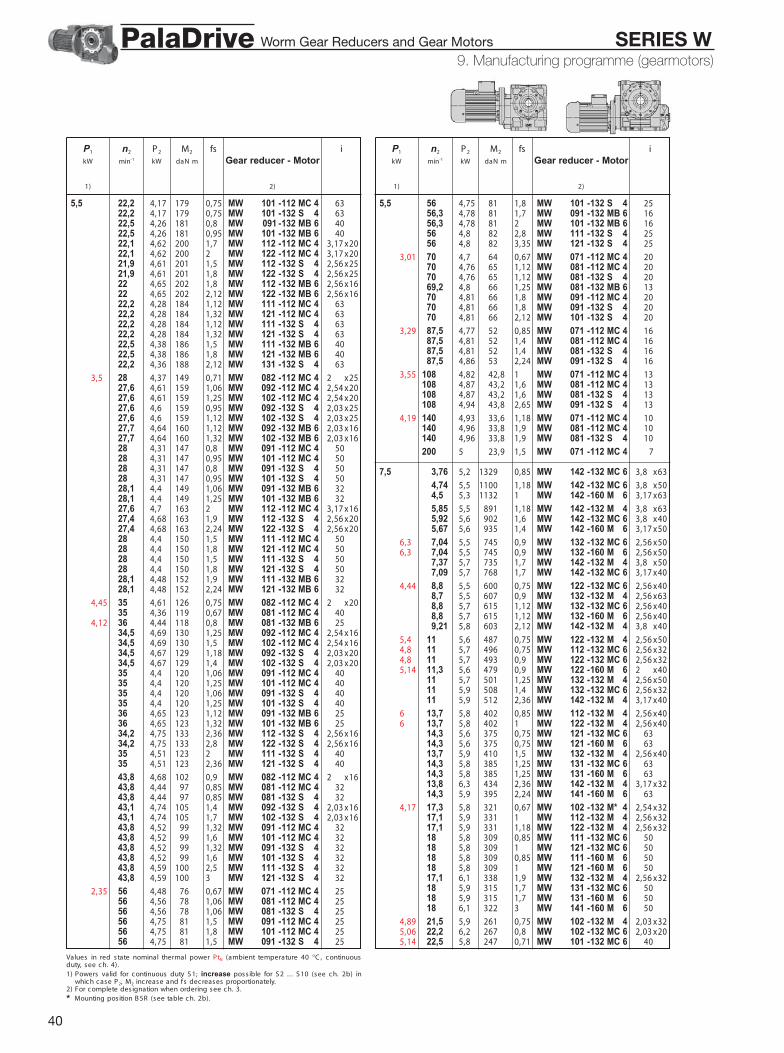
40
9 - Manufac turing programme (gearmotors )
P1 n2 P2 M2 fs ikW min-1 kW daN m Gear reducer - Motor
1) 2)
Values in red s tate nominal thermal power PtN (ambient temperature 40 °C , c ontinuousduty, s ee c h. 4).1) Powers valid for c ontinuous duty S 1; increase poss ible for S 2 .. . S 10 (see c h. 2b) in
whic h c ase P2, M2 inc rease and fs decreases proportionately.2) For c omplete des ignation when ordering see c h. 3.
* Mounting pos ition B 5R (see table c h. 2b).
5,5 22,2 4,17 179 0,75 MW 101 -112 MC 4 6322,2 4,17 179 0,75 MW 101 -132 S 4 6322,5 4,26 181 0,8 MW 091 -132 MB 6 4022,5 4,26 181 0,95 MW 101 -132 MB 6 4022,1 4,62 200 1,7 MW 112 -112 MC 4 23,17 x2022,1 4,62 200 2 MW 122 -112 MC 4 23,17 x2021,9 4,61 201 1,5 MW 112 -132 S 4 22,56 x2521,9 4,61 201 1,8 MW 122 -132 S 4 22,56 x2522 4,65 202 1,8 MW 112 -132 MB 6 22,56 x1622 4,65 202 2,12 MW 122 -132 MB 6 22,56 x1622,2 4,28 184 1,12 MW 111 -112 MC 4 6322,2 4,28 184 1,32 MW 121 -112 MC 4 6322,2 4,28 184 1,12 MW 111 -132 S 4 6322,2 4,28 184 1,32 MW 121 -132 S 4 6322,5 4,38 186 1,5 MW 111 -132 MB 6 4022,5 4,38 186 1,8 MW 121 -132 MB 6 4022,2 4,36 188 2,12 MW 131 -132 S 4 63
3,5 28 4,37 149 0,71 MW 082 -112 MC 4 22 x2527,6 4,61 159 1,06 MW 092 -112 MC 4 22,54 x2027,6 4,61 159 1,25 MW 102 -112 MC 4 22,54 x2027,6 4,6 159 0,95 MW 092 -132 S 4 22,03 x2527,6 4,6 159 1,12 MW 102 -132 S 4 22,03 x2527,7 4,64 160 1,12 MW 092 -132 MB 6 22,03 x1627,7 4,64 160 1,32 MW 102 -132 MB 6 22,03 x1628 4,31 147 0,8 MW 091 -112 MC 4 5028 4,31 147 0,95 MW 101 -112 MC 4 5028 4,31 147 0,8 MW 091 -132 S 4 5028 4,31 147 0,95 MW 101 -132 S 4 5028,1 4,4 149 1,06 MW 091 -132 MB 6 3228,1 4,4 149 1,25 MW 101 -132 MB 6 3227,6 4,7 163 2 MW 112 -112 MC 4 23,17 x1627,4 4,68 163 1,9 MW 112 -132 S 4 22,56 x2027,4 4,68 163 2,24 MW 122 -132 S 4 22,56 x2028 4,4 150 1,5 MW 111 -112 MC 4 5028 4,4 150 1,8 MW 121 -112 MC 4 5028 4,4 150 1,5 MW 111 -132 S 4 5028 4,4 150 1,8 MW 121 -132 S 4 5028,1 4,48 152 1,9 MW 111 -132 MB 6 3228,1 4,48 152 2,24 MW 121 -132 MB 6 32
4,45 35 4,61 126 0,75 MW 082 -112 MC 4 22 x2035 4,36 119 0,67 MW 081 -112 MC 4 40
4,12 36 4,44 118 0,8 MW 081 -132 MB 6 2534,5 4,69 130 1,25 MW 092 -112 MC 4 22,54 x1634,5 4,69 130 1,5 MW 102 -112 MC 4 22,54 x1634,5 4,67 129 1,18 MW 092 -132 S 4 22,03 x2034,5 4,67 129 1,4 MW 102 -132 S 4 22,03 x2035 4,4 120 1,06 MW 091 -112 MC 4 4035 4,4 120 1,25 MW 101 -112 MC 4 4035 4,4 120 1,06 MW 091 -132 S 4 4035 4,4 120 1,25 MW 101 -132 S 4 4036 4,65 123 1,12 MW 091 -132 MB 6 2536 4,65 123 1,32 MW 101 -132 MB 6 2534,2 4,75 133 2,36 MW 112 -132 S 4 22,56 x1634,2 4,75 133 2,8 MW 122 -132 S 4 22,56 x1635 4,51 123 2 MW 111 -132 S 4 4035 4,51 123 2,36 MW 121 -132 S 4 40
43,8 4,68 102 0,9 MW 082 -112 MC 4 22 x1643,8 4,44 97 0,85 MW 081 -112 MC 4 3243,8 4,44 97 0,85 MW 081 -132 S 4 3243,1 4,74 105 1,4 MW 092 -132 S 4 22,03 x1643,1 4,74 105 1,7 MW 102 -132 S 4 22,03 x1643,8 4,52 99 1,32 MW 091 -112 MC 4 3243,8 4,52 99 1,6 MW 101 -112 MC 4 3243,8 4,52 99 1,32 MW 091 -132 S 4 3243,8 4,52 99 1,6 MW 101 -132 S 4 3243,8 4,59 100 2,5 MW 111 -132 S 4 3243,8 4,59 100 3 MW 121 -132 S 4 32
2,35 56 4,48 76 0,67 MW 071 -112 MC 4 2556 4,56 78 1,06 MW 081 -112 MC 4 2556 4,56 78 1,06 MW 081 -132 S 4 2556 4,75 81 1,5 MW 091 -112 MC 4 2556 4,75 81 1,8 MW 101 -112 MC 4 2556 4,75 81 1,5 MW 091 -132 S 4 25
P1 n2 P2 M2 fs ikW min-1 kW daN m Gear reducer - Motor
1) 2)
5,5 56 4,75 81 1,8 MW 101 -132 S 4 2556,3 4,78 81 1,7 MW 091 -132 MB 6 1656,3 4,78 81 2 MW 101 -132 MB 6 1656 4,8 82 2,8 MW 111 -132 S 4 2556 4,8 82 3,35 MW 121 -132 S 4 25
3,01 70 4,7 64 0,67 MW 071 -112 MC 4 2070 4,76 65 1,12 MW 081 -112 MC 4 2070 4,76 65 1,12 MW 081 -132 S 4 2069,2 4,8 66 1,25 MW 081 -132 MB 6 1370 4,81 66 1,8 MW 091 -112 MC 4 2070 4,81 66 1,8 MW 091 -132 S 4 2070 4,81 66 2,12 MW 101 -132 S 4 20
3,29 87,5 4,77 52 0,85 MW 071 -112 MC 4 1687,5 4,81 52 1,4 MW 081 -112 MC 4 1687,5 4,81 52 1,4 MW 081 -132 S 4 1687,5 4,86 53 2,24 MW 091 -132 S 4 16
3,55 108 4,82 42,8 1 MW 071 -112 MC 4 13108 4,87 43,2 1,6 MW 081 -112 MC 4 13108 4,87 43,2 1,6 MW 081 -132 S 4 13108 4,94 43,8 2,65 MW 091 -132 S 4 13
4,19 140 4,93 33,6 1,18 MW 071 -112 MC 4 10140 4,96 33,8 1,9 MW 081 -112 MC 4 10140 4,96 33,8 1,9 MW 081 -132 S 4 10
200 5 23,9 1,5 MW 071 -112 MC 4 7
7,5 3,76 5,2 1329 0,85 MW 142 -132 MC 6 23,8 x63
4,74 5,5 1100 1,18 MW 142 -132 MC 6 23,8 x504,5 5,3 1132 1 MW 142 -160 M 6 23,17 x63
5,85 5,5 891 1,18 MW 142 -132 M 4 23,8 x635,92 5,6 902 1,6 MW 142 -132 MC 6 23,8 x405,67 5,6 935 1,4 MW 142 -160 M 6 23,17 x50
6,3 7,04 5,5 745 0,9 MW 132 -132 MC 6 22,56 x506,3 7,04 5,5 745 0,9 MW 132 -160 M 6 22,56 x50
7,37 5,7 735 1,7 MW 142 -132 M 4 23,8 x507,09 5,7 768 1,7 MW 142 -132 MC 6 23,17 x40
4,44 8,8 5,5 600 0,75 MW 122 -132 MC 6 22,56 x408,7 5,5 607 0,9 MW 132 -132 M 4 22,56 x638,8 5,7 615 1,12 MW 132 -132 MC 6 22,56 x408,8 5,7 615 1,12 MW 132 -160 M 6 22,56 x409,21 5,8 603 2,12 MW 142 -132 M 4 23,8 x40
5,4 11 5,6 487 0,75 MW 122 -132 M 4 22,56 x504,8 11 5,7 496 0,75 MW 112 -132 MC 6 22,56 x324,8 11 5,7 493 0,9 MW 122 -132 MC 6 22,56 x325,14 11,3 5,6 479 0,9 MW 122 -160 M 6 22 x40
11 5,7 501 1,25 MW 132 -132 M 4 22,56 x5011 5,9 508 1,4 MW 132 -132 MC 6 22,56 x3211 5,9 512 2,36 MW 142 -132 M 4 23,17 x40
6 13,7 5,8 402 0,85 MW 112 -132 M 4 22,56 x406 13,7 5,8 402 1 MW 122 -132 M 4 22,56 x40
14,3 5,6 375 0,75 MW 121 -132 MC 6 6314,3 5,6 375 0,75 MW 121 -160 M 6 6313,7 5,9 410 1,5 MW 132 -132 M 4 22,56 x4014,3 5,8 385 1,25 MW 131 -132 MC 6 6314,3 5,8 385 1,25 MW 131 -160 M 6 6313,8 6,3 434 2,36 MW 142 -132 M 4 23,17 x3214,3 5,9 395 2,24 MW 141 -160 M 6 63
4,17 17,3 5,8 321 0,67 MW 102 -132 M* 4 22,54 x3217,1 5,9 331 1 MW 112 -132 M 4 22,56 x3217,1 5,9 331 1,18 MW 122 -132 M 4 22,56 x3218 5,8 309 0,85 MW 111 -132 MC 6 5018 5,8 309 1 MW 121 -132 MC 6 5018 5,8 309 0,85 MW 111 -160 M 6 5018 5,8 309 1 MW 121 -160 M 6 5017,1 6,1 338 1,9 MW 132 -132 M 4 22,56 x3218 5,9 315 1,7 MW 131 -132 MC 6 5018 5,9 315 1,7 MW 131 -160 M 6 5018 6,1 322 3 MW 141 -160 M 6 50
4,89 21,5 5,9 261 0,75 MW 102 -132 M 4 22,03 x325,06 22,2 6,2 267 0,8 MW 102 -132 MC 6 22,03 x205,14 22,5 5,8 247 0,71 MW 101 -132 MC 6 40
9. Manufacturing programme (gearmotors)Worm Gear Reducers and Gear Motors SERIES WPalaDrive

41
9 - Manufac turing programme (gearmotors )
P1 n2 P2 M2 fs ikW min-1 kW daN m Gear reducer - Motor
1) 2)
Values in red s tate nominal thermal power PtN (ambient temperature 40 °C , c ontinuousduty, s ee c h. 4).1) Powers valid for c ontinuous duty S 1; increase poss ible for S 2 .. . S 10 (see ch. 2b) in
whic h c ase P2, M2 inc rease and fs decreases proportionately.2) For c omplete des ignation when ordering see c h. 3.
* Mounting pos ition B 5R (see table c h. 2b).
7,5 22,1 6,3 273 1,18 MW 112 -132 M* 4 23,17 x2021,9 6,3 274 1,12 MW 112 -132 M 4 22,56 x2522,1 6,3 273 1,5 MW 122 -132 M* 4 23,17 x2021,9 6,3 274 1,32 MW 122 -132 M 4 22,56 x2522 6,3 275 1,32 MW 112 -132 MC 6 22,56 x1622 6,3 275 1,5 MW 122 -132 MC 6 22,56 x1622,2 5,8 251 0,85 MW 111 -132 M 4 6322,2 5,8 251 1 MW 121 -132 M 4 6322,5 6 253 1,12 MW 111 -132 MC 6 4022,5 6 253 1,32 MW 121 -132 MC 6 4022,5 6 253 1,12 MW 111 -160 M 6 4022,5 6 253 1,32 MW 121 -160 M 6 4021,9 6,4 278 2,24 MW 132 -132 M 4 22,56 x2522,2 6 256 1,6 MW 131 -132 M 4 6322,5 6,1 258 2,12 MW 131 -132 MC 6 4022,5 6,1 258 2,12 MW 131 -160 M 6 40
5,8 27,6 6,3 217 0,75 MW 092 -132 M* 4 22,54 x2027,6 6,3 217 0,71 MW 092 -132 M 4 22,03 x25
5,8 27,6 6,3 217 0,9 MW 102 -132 M* 4 22,54 x2027,6 6,3 217 0,8 MW 102 -132 M 4 22,03 x25
5,55 27,7 6,3 218 0,95 MW 102 -132 MC 6 22,03 x1628 5,9 201 0,71 MW 101 -132 M 4 50
5,8 28,1 6 204 0,75 MW 091 -132 MC 6 325,8 28,1 6 204 0,9 MW 101 -132 MC 6 32
27,4 6,4 222 1,4 MW 112 -132 M 4 22,56 x2027,4 6,4 222 1,7 MW 122 -132 M 4 22,56 x2028 6 205 1,12 MW 111 -132 M 4 5028 6 205 1,32 MW 121 -132 M 4 5028,1 6,1 207 1,4 MW 111 -132 MC 6 3228,1 6,1 207 1,6 MW 121 -132 MC 6 3228,1 6,1 207 1,4 MW 111 -160 M 6 3228,1 6,1 207 1,6 MW 121 -160 M 6 3227,4 6,5 226 2,8 MW 132 -132 M 4 22,56 x2028 6,1 209 2,12 MW 131 -132 M 4 50
34,5 6,4 177 0,95 MW 092 -132 M* 4 22,54 x1634,5 6,4 176 0,9 MW 092 -132 M 4 22,03 x2034,5 6,4 176 1,06 MW 102 -132 M 4 22,03 x2035 6 164 0,75 MW 091 -132 M 4 4035 6 164 0,9 MW 101 -132 M 4 4036 6,3 168 0,85 MW 091 -132 MC 6 2536 6,3 168 1 MW 101 -132 MC 6 2534,2 6,5 181 1,7 MW 112 -132 M 4 22,56 x1634,2 6,5 181 2 MW 122 -132 M 4 22,56 x1635 6,1 168 1,4 MW 111 -132 M 4 4035 6,1 168 1,7 MW 121 -132 M 4 4035 6,2 170 2,65 MW 131 -132 M 4 40
43,1 6,5 143 1,06 MW 092 -132 M 4 22,03 x1643,1 6,5 143 1,25 MW 102 -132 M 4 22,03 x1643,8 6,2 135 1 MW 091 -132 M 4 3243,8 6,2 135 1,18 MW 101 -132 M 4 3245 6,4 136 1,25 MW 101 -132 MC 6 2043,8 6,3 137 1,8 MW 111 -132 M 4 3243,8 6,3 137 2,12 MW 121 -132 M 4 32
5,7 56 6,2 106 0,8 MW 081 -132 M 4 2556 6,5 110 1,12 MW 091 -132 M 4 2556 6,5 110 1,32 MW 091 -132 M 4 2556,3 6,5 111 1,25 MW 091 -132 MC 6 1656,3 6,5 111 1,5 MW 101 -132 MC 6 1656 6,5 112 2 MW 111 -132 M 4 2556 6,5 112 2,36 MW 121 -132 M 4 25
70 6,5 89 0,8 MW 081 -132 M 4 2070 6,6 89 1,32 MW 091 -132 M 4 2070 6,6 89 1,6 MW 101 -132 M 4 2069,2 6,7 92 1,5 MW 091 -132 MC 6 1369,2 6,7 92 1,8 MW 101 -132 MC 6 1370 6,6 90 2,5 MW 111 -132 M 4 2070 6,6 90 3 MW 121 -132 M 4 20
87,5 6,6 72 1 MW 081 -132 M 4 1687,5 6,6 72 1,6 MW 091 -132 M 4 1687,5 6,6 72 1,9 MW 101 -132 M 4 16
108 6,6 59 1,18 MW 081 -132 M 4 13108 6,7 60 1,9 MW 091 -132 M 4 13
P1 n2 P2 M2 fs ikW min-1 kW daN m Gear reducer - Motor
1) 2)
7,5 140 6,8 46,1 1,4 MW 081 -132 M 4 10140 6,8 46,4 2,24 MW 091 -132 M 4 10
9,2 5,85 6,7 1093 1 MW 142 -132 MB 4 23,8 x637,37 7 901 1,4 MW 142 -132 MB 4 23,8 x50
7,6 8,7 6,8 745 0,71 MW 132 -132 MB 4 22,56 x639,21 7,1 740 1,7 MW 142 -132 MB 4 23,8 x40
11 7 614 1 MW 132 -132 MB 4 22,56 x5011 7,3 629 1,9 MW 142 -132 MB 4 23,17 x40
6 13,7 7,1 493 0,67 MW 112 -132 MB 4 22,56 x406 13,7 7,1 493 0,8 MW 122 -132 MB 4 22,56 x40
13,7 7,2 503 1,25 MW 132 -132 MB 4 22,56 x4013,8 7,7 532 1,9 MW 142 -132 MB 4 23,17 x32
6,6 17,1 7,3 406 0,85 MW 112 -132 MB 4 22,56 x326,6 17,1 7,3 406 1 MW 122 -132 MB 4 22,56 x32
17,1 7,4 415 1,6 MW 132 -132 MB 4 22,56 x3217,6 7,9 426 2,8 MW 142 -132 MB 4 23,17 x2521,9 7,7 336 0,9 MW 112 -132 MB 4 22,56 x2521,9 7,7 336 1,06 MW 122 -132 MB 4 22,56 x2522,2 7,2 308 0,67 MW 111 -132 MB 4 6322,2 7,2 308 0,8 MW 121 -132 MB 4 6321,9 7,8 341 1,8 MW 132 -132 MB 4 22,56 x2522,2 7,3 314 1,32 MW 131 -132 MB 4 63
6,4 27,6 7,7 266 0,67 MW 102 -132 MB 4 22,03 x2527,4 7,8 273 1,12 MW 112 -132 MB 4 22,56 x2027,4 7,8 273 1,32 MW 122 -132 MB 4 22,56 x2028 7,4 251 0,9 MW 111 -132 MB 4 5028 7,4 251 1,06 MW 121 -132 MB 4 5027,4 7,9 277 2,24 MW 132 -132 MB 4 22,56 x2028 7,5 256 1,7 MW 131 -132 MB 4 50
6,9 34,5 7,8 216 0,71 MW 092 -132 MB 4 22,03 x206,9 34,5 7,8 216 0,85 MW 102 -132 MB 4 22,03 x207,1 35 7,4 201 0,75 MW 101 -132 MB 4 40
34,2 7,9 222 1,4 MW 112 -132 MB 4 22,56 x1634,2 7,9 222 1,7 MW 122 -132 MB 4 22,56 x1635 7,5 206 1,18 MW 111 -132 MB 4 4035 7,5 206 1,4 MW 121 -132 MB 4 4034,2 8,1 226 2,65 MW 132 -132 MB 4 22,56 x1635 7,6 209 2,12 MW 131 -132 MB 4 40
7,5 43,1 7,9 176 0,85 MW 092 -132 MB 4 22,03 x167,5 43,1 7,9 176 1 MW 102 -132 MB 4 22,03 x16
43,8 7,6 165 0,8 MW 091 -132 MB 4 3243,8 7,6 165 0,95 MW 101 -132 MB 4 3243,8 7,7 168 1,4 MW 111 -132 MB 4 3243,8 7,7 168 1,7 MW 121 -132 MB 4 3243,8 7,8 170 2,8 MW 131 -132 MB 4 32
56 7,9 135 0,9 MW 091 -132 MB 4 2556 7,9 135 1,06 MW 101 -132 MB 4 2556 8 137 1,7 MW 111 -132 MB 4 2556 8 137 2 MW 121 -132 MB 4 25
7,2 70 8 109 0,67 MW 081 -132 MB 4 2070 8 110 1,12 MW 091 -132 MB 4 2070 8 110 1,32 MW 101 -132 MB 4 2070 8,1 111 2 MW 111 -132 MB 4 2070 8,1 111 2,36 MW 121 -132 MB 4 20
7,8 87,5 8 88 0,8 MW 081 -132 MB 4 1687,5 8,1 89 1,32 MW 091 -132 MB 4 1687,5 8,1 89 1,6 MW 101 -132 MB 4 1687,5 8,2 89 2,5 MW 111 -132 MB 4 1687,5 8,2 89 3 MW 121 -132 MB 4 16
108 8,1 72 1 MW 081 -132 MB 4 13108 8,3 73 1,6 MW 091 -132 MB 4 13108 8,3 73 1,9 MW 101 -132 MB 4 13
140 8,3 57 1,12 MW 081 -132 MB 4 10140 8,3 57 1,8 MW 091 -132 MB 4 10140 8,3 57 2,12 MW 101 -132 MB 4 10
11 8 4,5 7,8 1660 0,67 MW 142 -160 L 6 23,17 x63
9,1 5,85 8 1307 0,8 MW 142 -132 MC 4 23,8 x638,9 5,67 8,1 1372 0,95 MW 142 -160 L 6 23,17 x50
9. Manufacturing programme (gearmotors)Worm Gear Reducers and Gear Motors SERIES WPalaDrive

42
9 - Manufac turing programme (gearmotors )
P1 n2 P2 M2 fs ikW min-1 kW daN m Gear reducer - Motor
1) 2)
Values in red s tate nominal thermal power PtN (ambient temperature 40 °C , c ontinuousduty, s ee c h. 4).1) Powers valid for c ontinuous duty S 1; increase poss ible for S 2 .. . S 10 (see c h. 2b) in
whic h c ase P2, M2 inc rease and fs decreases proportionately.2) For c omplete des ignation when ordering see c h. 3.
11 7,37 8,3 1077 1,12 MW 142 -132 MC 4 23,8 x507 8,2 1117 0,9 MW 142 -160 M 4 23,17 x637,09 8,4 1127 1,18 MW 142 -160 L 6 23,17 x40
6,9 8,8 8,3 901 0,8 MW 132 -160 L 6 22,56 x409,21 8,5 884 1,4 MW 142 -132 MC 4 23,8 x408,82 8,5 919 1,32 MW 142 -160 M 4 23,17 x508,8 8,5 925 1,4 MW 142 -160 L 6 22,56 x40
8,5 11 8,4 734 0,85 MW 132 -132 MC 4 22,56 x508,5 11 8,4 734 0,85 MW 132 -160 M 4 22,56 x50
11 8,7 752 1,6 MW 142 -132 MC 4 23,17 x4011 8,7 752 1,6 MW 142 -160 M 4 23,17 x40
6 13,7 8,5 590 0,67 MW 122 -132 MC 4 22,56 x405,7 14,1 8,5 580 0,71 MW 122 -160 L 6 22 x329,3 13,7 8,6 602 1,06 MW 132 -132 MC 4 22,56 x409,3 13,7 8,6 602 1,06 MW 132 -160 M 4 22,56 x409 14,1 8,8 594 1,18 MW 132 -160 L 6 22 x32
14,3 8,4 564 0,85 MW 131 -160 L 6 6313,8 9,2 636 1,6 MW 142 -132 MC 4 23,17 x3213,7 8,8 616 1,8 MW 142 -160 M 4 22,56 x4014,1 9,3 630 2 MW 142 -160 L 6 22,56 x2514,3 8,7 579 1,5 MW 141 -160 L 6 63
6,6 17,1 8,7 485 0,71 MW 112 -132 MC 4 22,56 x326,6 17,1 8,7 485 0,8 MW 122 -132 MC 4 22,56 x327 17,5 8,6 470 0,67 MW 112 -160 M 4 22 x407 17,5 8,6 470 0,8 MW 122 -160 M 4 22 x407,5 18 8,5 453 0,71 MW 121 -160 L 6 50
17,1 8,9 496 1,32 MW 132 -132 MC 4 22,56 x3217,5 8,8 479 1,18 MW 132 -160 M 4 22 x4018 8,7 462 1,18 MW 131 -160 L 6 5017,6 9,4 509 2,36 MW 142 -132 MC 4 23,17 x2517,1 9,3 518 1,9 MW 142 -160 M 4 22,56 x3218 8,9 473 2,12 MW 141 -160 L 6 50
8,5 21,9 9,2 402 0,75 MW 112 -132 MC 4 22,56 x258,5 21,9 9,2 402 0,9 MW 122 -132 MC 4 22,56 x257,7 21,9 8,8 386 0,8 MW 112 -160 M 4 22 x327,7 21,9 8,8 386 0,95 MW 122 -160 M 4 22 x328 22,5 9,2 392 0,85 MW 112 -160 L 6 22 x208 22,5 9,2 392 1 MW 122 -160 L 6 22 x209,3 22,2 8,6 368 0,67 MW 121 -132 MC 4 639,3 22,2 8,6 368 0,67 MW 121 -160 M 4 638,3 22,5 8,8 372 0,75 MW 111 -160 L 6 408,3 22,5 8,8 372 0,9 MW 121 -160 L 6 40
21,9 9,4 408 1,5 MW 132 -132 MC 4 22,56 x2521,9 9 393 1,6 MW 132 -160 M 4 22 x3222,2 8,7 375 1,06 MW 131 -132 MC 4 6322,2 8,7 375 1,06 MW 131 -160 M 4 6322,5 8,9 378 1,4 MW 131 -160 L 6 4021,9 9,5 414 2,65 MW 142 -160 M 4 22,56 x2522,2 8,9 383 1,9 MW 141 -160 M 4 63
9,2 27,4 9,4 326 0,95 MW 112 -132 MC 4 22,56 x209,2 27,4 9,4 326 1,12 MW 122 -132 MC 4 22,56 x20
28 9,3 318 0,9 MW 112 -160 M 4 22 x2528 9,3 318 1,06 MW 122 -160 M 4 22 x25
8,7 28,1 9,4 319 1,06 MW 112 -160 L 6 22 x168,7 28,1 9,4 319 1,25 MW 122 -160 L 6 22 x16
28 8,8 300 0,75 MW 111 -132 MC 4 5028 8,8 300 0,9 MW 121 -132 MC 4 5028 8,8 300 0,75 MW 111 -160 M 4 5028 8,8 300 0,9 MW 121 -160 M 4 50
9,1 28,1 9 304 0,95 MW 111 -160 L 6 329,1 28,1 9 304 1,12 MW 121 -160 L 6 32
27,4 9,5 331 1,9 MW 132 -132 MC 4 22,56 x2028 9,5 323 1,8 MW 132 -160 M 4 22 x2528 9 306 1,5 MW 131 -132 MC 4 5028 9 306 1,5 MW 131 -160 M 4 5028,1 9,1 310 1,8 MW 131 -160 L 6 3227,4 9,6 334 3,35 MW 142 -160 M 4 22,56 x2028 9,1 311 2,5 MW 141 -160 M 4 50
6,9 34,5 9,3 259 0,71 MW 102 -132 MC 4 22,03 x2034,2 9,5 265 1,18 MW 112 -132 MC 4 22,56 x1634,2 9,5 265 1,4 MW 122 -132 MC 4 22,56 x1635 9,5 258 1,12 MW 112 -160 M 4 22 x20
P1 n2 P2 M2 fs ikW min-1 kW daN m Gear reducer - Motor
1) 2)
11 35 9,5 258 1,32 MW 122 -160 M 4 22 x2035 9 246 1 MW 111 -132 MC 4 4035 9 246 1,18 MW 121 -132 MC 4 4035 9 246 1 MW 111 -160 M 4 4035 9 246 1,18 MW 121 -160 M 4 4034,2 9,7 271 2,12 MW 132 -132 MC 4 22,56 x1635 9,6 261 2,24 MW 132 -160 M 4 22 x2035 9,1 249 1,8 MW 131 -132 MC 4 4035 9,1 249 1,8 MW 131 -160 M 4 40
7,5 43,1 9,5 210 0,85 MW 102 -132 MC 4 22,03 x168 43,8 9 198 0,67 MW 091 -132 MC 4 328 43,8 9 198 0,8 MW 101 -132 MC 4 32
43,8 9,6 209 1,4 MW 112 -160 M 4 22 x1643,8 9,6 209 1,6 MW 122 -160 M 4 22 x1643,8 9,2 201 1,18 MW 111 -132 MC 4 3243,8 9,2 201 1,5 MW 121 -132 MC 4 3243,8 9,2 201 1,18 MW 111 -160 M 4 3243,8 9,2 201 1,4 MW 121 -160 M 4 3245 9,5 203 1,32 MW 111 -160 L 6 2045 9,5 203 1,6 MW 121 -160 L 6 2043,8 9,8 214 2,5 MW 132 -160 M 4 22 x1643,8 9,3 203 2,24 MW 131 -160 M 4 32
56 9,5 162 0,75 MW 091 -132 MC 4 2556 9,5 162 0,9 MW 101 -132 MC 4 2556 9,6 164 1,4 MW 111 -132 MC 4 2556 9,6 164 1,7 MW 121 -132 MC 4 2556 9,6 164 1,4 MW 111 -160 M 4 2556 9,6 164 1,7 MW 121 -160 M 4 2556,3 9,7 164 1,6 MW 111 -160 L 6 1656,3 9,7 164 1,9 MW 121 -160 L 6 1656 9,7 165 2,65 MW 131 -160 M 4 25
70 9,6 131 0,9 MW 091 -132 MC 4 2070 9,6 131 1,12 MW 101 -132 MC 4 2070 9,7 132 1,7 MW 111 -132 MC 4 2070 9,7 132 2 MW 121 -132 MC 4 2070 9,7 132 1,7 MW 111 -160 M 4 2070 9,7 132 2 MW 121 -160 M 4 20
87,5 9,7 106 1,12 MW 091 -132 MC 4 1687,5 9,7 106 1,32 MW 101 -132 MC 4 1687,5 9,8 107 2 MW 111 -160 M 4 1687,5 9,8 107 2,5 MW 121 -160 M 4 16
108 9,9 88 1,32 MW 091 -132 MC 4 13108 9,9 88 1,6 MW 101 -132 MC 4 13108 10 88 2,36 MW 111 -160 M 4 13108 10 88 2,8 MW 121 -160 M 4 13
140 10 68 1,5 MW 091 -132 MC 4 10140 10 68 1,8 MW 101 -132 MC 4 10140 10 68 2,8 MW 111 -160 M 4 10140 10 68 3,15 MW 121 -160 M 4 10
15 10,6 7 11,2 1523 0,67 MW 142 -160 L 4 23,17 x6310,1 7,04 11,3 1537 0,8 MW 142 -180 L 6 22,56 x50
11,8 8,82 11,6 1253 0,95 MW 142 -160 L 4 23,17 x50
11 11,8 1025 1,18 MW 142 -160 L 4 23,17 x40
9,3 13,7 11,8 821 0,75 MW 132 -160 L 4 22,56 x409 14,1 11,9 811 0,85 MW 132 -180 L 6 22 x32
13,7 12 840 1,32 MW 142 -160 L 4 22,56 x4014,1 12,7 859 1,4 MW 142 -180 L 6 22,56 x2514,3 11,8 789 1,12 MW 141 -180 L 6 63
10,9 17,5 12 654 0,9 MW 132 -160 L 4 22 x4011,7 18 11,9 630 0,85 MW 131 -180 L 6 50
17,1 12,7 707 1,4 MW 142 -160 L 4 22,56 x3217,6 12,8 695 1,9 MW 142 -180 L 6 22,56 x2018 12,2 645 1,5 MW 141 -180 L 6 50
7,7 21,9 12,1 526 0,71 MW 122 -160 L 4 22 x3212,2 21,9 12,3 536 1,12 MW 132 -160 L 4 22 x3212,6 22,5 12,8 544 1,25 MW 132 -180 L 6 22 x20
22,2 11,9 512 0,8 MW 131 -160 L 4 6322,5 12,1 515 1,06 MW 131 -180 L 6 4021,9 12,9 564 2 MW 142 -160 L 4 22,56 x25
9. Manufacturing programme (gearmotors)Worm Gear Reducers and Gear Motors SERIES WPalaDrive

43
9 - Manufac turing programme (gearmotors )
P1 n2 P2 M2 fs ikW min-1 kW daN m Gear reducer - Motor
1) 2)
P1 n2 P2 M2 fs ikW min-1 kW daN m Gear reducer - Motor
1) 2)
15 22,2 12,2 523 1,4 MW 141 -160 L 4 6322,5 12,4 525 1,8 MW 141 -180 L 6 40
10 28 12,7 434 0,75 MW 122 -160 L 4 12 x2510,3 28 12 410 0,67 MW 121 -160 L 4 50
9,1 28,1 12,2 415 0,71 MW 111 -180 L 6 329,1 28,1 12,2 415 0,8 MW 121 -180 L 6 32
28 12,9 440 1,32 MW 132 -160 L 4 12 x2528 12,2 417 1,06 MW 131 -160 L 4 5028,1 12,5 423 1,32 MW 131 -180 L 6 3227,4 13,1 456 2,5 MW 142 -160 L 4 12,56 x2028 12,4 425 1,9 MW 141 -160 L 4 50
10,8 35 12,9 352 0,8 MW 112 -160 L 4 12 x2010,8 35 12,9 352 1 MW 122 -160 L 4 12 x2011,4 35 12,3 335 0,71 MW 111 -160 L 4 4011,4 35 12,3 335 0,85 MW 121 -160 L 4 40
35 13,1 356 1,6 MW 132 -160 L 4 12 x2035 12,5 340 1,32 MW 131 -160 L 4 4036 13 345 1,5 MW 131 -180 L 6 2534,2 13,4 373 2,8 MW 142 -160 L 4 12,56 x1635 12,6 344 2,36 MW 141 -160 L 4 40
11,8 43,8 13,1 285 1 MW 112 -160 L 4 12 x1611,8 43,8 13,1 285 1,18 MW 122 -160 L 4 12 x1612,5 43,8 12,5 274 0,9 MW 111 -160 L 4 3212,5 43,8 12,5 274 1,06 MW 121 -160 L 4 32
43,8 13,3 291 1,9 MW 132 -160 L 4 12 x1643,8 12,7 277 1,7 MW 131 -160 L 4 3245 13,2 279 1,9 MW 131 -180 L 6 2043,8 13,1 287 2,5 MW 141 -160 L 4 32
10,4 56 12,9 221 0,67 MW 101 -160 L 4 2556 13,1 223 1 MW 111 -160 L 4 2556 13,1 223 1,18 MW 121 -160 L 4 2556,3 13,2 224 1,18 MW 111 -180 L 6 1656,3 13,2 224 1,4 MW 121 -180 L 6 1656 13,2 225 1,9 MW 131 -160 L 4 2556,3 13,4 228 2,12 MW 131 -180 L 6 16
11,2 70 13,1 179 0,67 MW 091 -160 L 4 2011,2 70 13,1 179 0,8 MW 101 -160 L 4 20
70 13,2 180 1,25 MW 111 -160 L 4 2070 13,2 180 1,5 MW 121 -160 L 4 2069,2 13,4 185 1,4 MW 111 -180 L 6 1369,2 13,4 185 1,7 MW 121 -180 L 6 1370 13,3 182 2,36 MW 131 -160 L 4 20
12,2 87,5 13,3 145 0,8 MW 091 -160 L 4 1612,2 87,5 13,3 145 0,95 MW 101 -160 L 4 16
87,5 13,4 146 1,5 MW 111 -160 L 4 1687,5 13,4 146 1,8 MW 121 -160 L 4 1687,5 13,6 148 2,8 MW 131 -160 L 4 16
108 13,5 120 0,95 MW 091 -160 L 4 13108 13,5 120 1,12 MW 101 -160 L 4 13108 13,6 120 1,8 MW 111 -160 L 4 13108 13,6 120 2,12 MW 121 -160 L 4 13
140 13,6 93 1,12 MW 091 -160 L 4 10140 13,6 93 1,32 MW 101 -160 L 4 10140 13,7 93 2 MW 111 -160 L 4 10140 13,7 93 2,36 MW 121 -160 L 4 10
18,5 11 8,8 14,3 1556 0,8 MW 142 -200 LR 6 12,56 x40
13,6 11 14,5 1266 0,9 MW 142 -180 M 4 12,56 x50
14,9 13,7 14,9 1036 1,06 MW 142 -180 M 4 12,56 x4014,3 14,6 974 0,9 MW 141 -200 LR 6 63
10,9 17,5 14,8 806 0,71 MW 132 -180 M 4 12 x4011,7 18 14,7 778 0,71 MW 131 -200 LR 6 50
17,1 15,6 871 1,12 MW 142 -180 M 4 12,56 x3218 15,8 839 1,4 MW 142 -200 LR 6 12 x2518 15 795 1,25 MW 141 -200 LR 6 50
12,2 21,9 15,1 661 0,9 MW 132 -180 M 4 12 x3212,8 22,5 15 636 0,85 MW 131 -200 LR 6 40
21,9 16 696 1,6 MW 142 -180 M 4 12,56 x2522,5 16 678 1,8 MW 142 -200 LR 6 12 x2022,2 15 645 1,12 MW 141 -180 M 4 63
18,5 22,5 15,2 647 1,5 MW 141 -200 LR 6 40
28 15,9 543 1,06 MW 132 -180 M 4 12 x2528 15,1 515 0,85 MW 131 -180 M 4 50
14,5 28,1 15,4 522 1,06 MW 131 -200 LR 6 3227,4 16,1 562 2 MW 142 -180 M 4 12,56 x2028 15,4 524 1,5 MW 141 -180 M 4 50
10,8 35 15,9 434 0,67 MW 112 -180 M 4 12 x2010,8 35 15,9 434 0,8 MW 122 -180 M 4 12 x2011,4 35 15,2 413 0,71 MW 121 -180 M 4 40
35 16,1 439 1,32 MW 132 -180 M 4 12 x2035 15,4 419 1,06 MW 131 -180 M 4 4036 16 425 1,25 MW 131 -200 LR 6 2534,2 16,5 460 2,36 MW 142 -180 M 4 12,56 x1635 15,5 424 1,9 MW 141 -180 M 4 40
11,8 43,8 16,1 352 0,8 MW 112 -180 M 4 12 x1611,8 43,8 16,1 352 0,95 MW 122 -180 M 4 12 x1612,5 43,8 15,5 337 0,71 MW 111 -180 M 4 3212,5 43,8 15,5 337 0,85 MW 121 -180 M 4 32
43,8 16,5 359 1,5 MW 132 -180 M 4 12 x1643,8 15,7 342 1,32 MW 131 -180 M 4 3245 16,2 345 1,6 MW 131 -200 LR 6 2043,8 16,2 354 2 MW 141 -180 M 4 32
56 16,1 275 0,85 MW 111 -180 M 4 2556 16,1 275 1 MW 121 -180 M 4 2556 16,3 278 1,5 MW 131 -180 M 4 2556,3 16,5 281 1,8 MW 131 -200 LR 6 1656 16,4 280 2,8 MW 141 -180 M 4 25
70 16,3 223 1 MW 111 -180 M 4 2070 16,3 223 1,18 MW 121 -180 M 4 2070 16,5 224 1,9 MW 131 -180 M 4 20
87,5 16,5 180 1,18 MW 111 -180 M 4 1687,5 16,5 180 1,4 MW 121 -180 M 4 1687,5 16,7 183 2,24 MW 131 -180 M 4 16
108 16,8 149 1,4 MW 111 -180 M 4 13108 16,8 149 1,7 MW 121 -180 M 4 13108 16,8 149 2,65 MW 131 -180 M 4 13
140 16,9 115 1,6 MW 111 -180 M 4 10140 16,9 115 1,9 MW 121 -180 M 4 10
22 11 8,8 17,1 1851 0,67 MW 142 -200 L 6 12,56 x40
13,6 11 17,3 1506 0,75 MW 142 -180 L 4 12,56 x50
14,9 13,7 17,7 1232 0,9 MW 142 -180 L 4 12,56 x4016,8 14,3 17,3 1158 0,75 MW 141 -200 L 6 63
17,1 18,6 1036 0,95 MW 142 -180 L 4 12,56 x3218,6 18 18,8 998 1,18 MW 142 -200 L 6 12 x25
18 17,8 946 1,06 MW 141 -200 L 6 50
12,2 21,9 18 786 0,8 MW 132 -180 L 4 12 x3212,8 22,5 17,8 756 0,71 MW 131 -200 L 6 40
21,9 19 828 1,32 MW 142 -180 L 4 12,56 x2522,5 19 806 1,5 MW 142 -200 L 6 12 x2022,2 17,8 767 0,95 MW 141 -180 L 4 6322,5 18,1 770 1,25 MW 141 -200 L 6 40
15,7 28 18,9 645 0,9 MW 132 -180 L 4 12 x2516,2 28 17,9 612 0,71 MW 131 -180 L 4 5014,5 28,1 18,3 621 0,9 MW 131 -200 L 6 32
27,4 19,2 668 1,7 MW 142 -180 L 4 12,56 x2028 18,3 623 1,25 MW 141 -180 L 4 5028,1 19 644 1,32 MW 141 -200 L 6 32
17 35 19,2 523 1,12 MW 132 -180 L 4 12 x2017,7 35 18,3 499 0,9 MW 131 -180 L 4 4018,3 36 19,1 506 1,06 MW 131 -200 L 6 25
34,2 19,6 547 1,9 MW 142 -180 L 4 12,56 x1635 18,5 504 1,6 MW 141 -180 L 4 4036 19,3 513 1,8 MW 141 -200 L 6 25
12,5 43,8 18,4 401 0,71 MW 121 -180 L 4 3243,8 19,6 427 1,25 MW 132 -180 L 4 12 x1643,8 18,6 406 1,12 MW 131 -180 L 4 3245 19,3 410 1,32 MW 131 -200 L 6 2043,8 19,3 421 1,7 MW 1 41 -180 L 4 32
Values in red s tate nominal thermal power PtN (ambient temperature 40 °C , c ontinuousduty, s ee c h. 4).1) Powers valid for c ontinuous duty S 1; increase poss ible for S 2 .. . S 10 (see ch. 2b) in
whic h c ase P2, M2 inc rease and fs decreases proportionately.2) For c omplete des ignation when ordering see c h. 3.
9. Manufacturing programme (gearmotors)Worm Gear Reducers and Gear Motors SERIES WPalaDrive
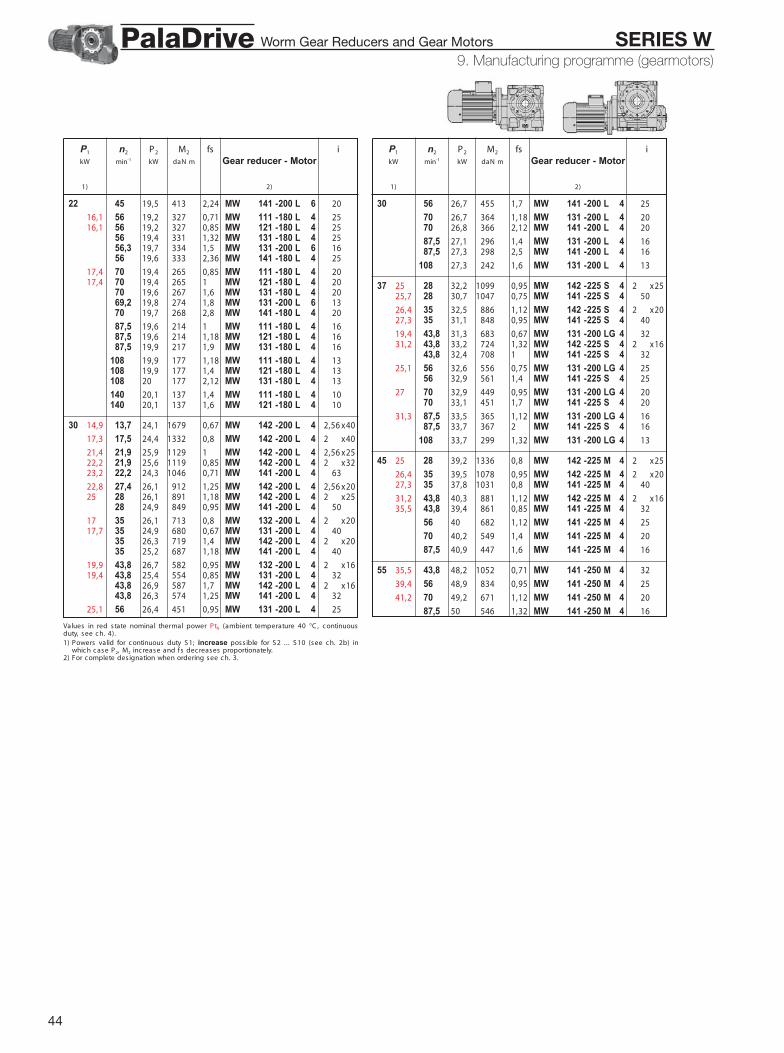
44
9 - Manufac turing programme (gearmotors )
P1 n2 P2 M2 fs ikW min-1 kW daN m Gear reducer - Motor
1) 2)
22 45 19,5 413 2,24 MW 141 -200 L 6 20
16,1 56 19,2 327 0,71 MW 111 -180 L 4 2516,1 56 19,2 327 0,85 MW 121 -180 L 4 25
56 19,4 331 1,32 MW 131 -180 L 4 2556,3 19,7 334 1,5 MW 131 -200 L 6 1656 19,6 333 2,36 MW 141 -180 L 4 25
17,4 70 19,4 265 0,85 MW 111 -180 L 4 2017,4 70 19,4 265 1 MW 121 -180 L 4 20
70 19,6 267 1,6 MW 131 -180 L 4 2069,2 19,8 274 1,8 MW 131 -200 L 6 1370 19,7 268 2,8 MW 141 -180 L 4 20
87,5 19,6 214 1 MW 111 -180 L 4 1687,5 19,6 214 1,18 MW 121 -180 L 4 1687,5 19,9 217 1,9 MW 131 -180 L 4 16
108 19,9 177 1,18 MW 111 -180 L 4 13108 19,9 177 1,4 MW 121 -180 L 4 13108 20 177 2,12 MW 131 -180 L 4 13
140 20,1 137 1,4 MW 111 -180 L 4 10140 20,1 137 1,6 MW 121 -180 L 4 10
30 14,9 13,7 24,1 1679 0,67 MW 142 -200 L 4 22,56 x40
17,3 17,5 24,4 1332 0,8 MW 142 -200 L 4 22 x40
21,4 21,9 25,9 1129 1 MW 142 -200 L 4 22,56 x2522,2 21,9 25,6 1119 0,85 MW 142 -200 L 4 22 x3223,2 22,2 24,3 1046 0,71 MW 141 -200 L 4 63
22,8 27,4 26,1 912 1,25 MW 142 -200 L 4 22,56 x2025 28 26,1 891 1,18 MW 142 -200 L 4 22 x25
28 24,9 849 0,95 MW 141 -200 L 4 50
17 35 26,1 713 0,8 MW 132 -200 L 4 22 x2017,7 35 24,9 680 0,67 MW 131 -200 L 4 40
35 26,3 719 1,4 MW 142 -200 L 4 22 x2035 25,2 687 1,18 MW 141 -200 L 4 40
19,9 43,8 26,7 582 0,95 MW 132 -200 L 4 22 x1619,4 43,8 25,4 554 0,85 MW 131 -200 L 4 32
43,8 26,9 587 1,7 MW 142 -200 L 4 22 x1643,8 26,3 574 1,25 MW 141 -200 L 4 32
25,1 56 26,4 451 0,95 MW 131 -200 L 4 25
P1 n2 P2 M2 fs ikW min-1 kW daN m Gear reducer - Motor
1) 2)
30 56 26,7 455 1,7 MW 141 -200 L 4 25
70 26,7 364 1,18 MW 131 -200 L 4 2070 26,8 366 2,12 MW 141 -200 L 4 20
87,5 27,1 296 1,4 MW 131 -200 L 4 1687,5 27,3 298 2,5 MW 141 -200 L 4 16
108 27,3 242 1,6 MW 131 -200 L 4 13
37 25 28 32,2 1099 0,95 MW 142 -225 S 4 22 x2525,7 28 30,7 1047 0,75 MW 141 -225 S 4 50
26,4 35 32,5 886 1,12 MW 142 -225 S 4 22 x2027,3 35 31,1 848 0,95 MW 141 -225 S 4 40
19,4 43,8 31,3 683 0,67 MW 131 -200 LG 4 3231,2 43,8 33,2 724 1,32 MW 142 -225 S 4 22 x16
43,8 32,4 708 1 MW 141 -225 S 4 32
25,1 56 32,6 556 0,75 MW 131 -200 LG 4 2556 32,9 561 1,4 MW 141 -225 S 4 25
27 70 32,9 449 0,95 MW 131 -200 LG 4 2070 33,1 451 1,7 MW 141 -225 S 4 20
31,3 87,5 33,5 365 1,12 MW 131 -200 LG 4 1687,5 33,7 367 2 MW 141 -225 S 4 16
108 33,7 299 1,32 MW 131 -200 LG 4 13
45 25 28 39,2 1336 0,8 MW 142 -225 M 4 22 x25
26,4 35 39,5 1078 0,95 MW 142 -225 M 4 22 x2027,3 35 37,8 1031 0,8 MW 141 -225 M 4 40
31,2 43,8 40,3 881 1,12 MW 142 -225 M 4 22 x1635,5 43,8 39,4 861 0,85 MW 141 -225 M 4 32
56 40 682 1,12 MW 141 -225 M 4 25
70 40,2 549 1,4 MW 141 -225 M 4 20
87,5 40,9 447 1,6 MW 141 -225 M 4 16
55 35,5 43,8 48,2 1052 0,71 MW 141 -250 M 4 32
39,4 56 48,9 834 0,95 MW 141 -250 M 4 25
41,2 70 49,2 671 1,12 MW 141 -250 M 4 20
87,5 50 546 1,32 MW 141 -250 M 4 16
Values in red s tate nominal thermal power PtN (ambient temperature 40 °C , c ontinuousduty, s ee c h. 4).1) Powers valid for c ontinuous duty S 1; increase poss ible for S 2 .. . S 10 (see c h. 2b) in
whic h c ase P2, M2 inc rease and fs decreases proportionately.2) For c omplete des ignation when ordering see c h. 3.
9. Manufacturing programme (gearmotors)Worm Gear Reducers and Gear Motors SERIES WPalaDrive
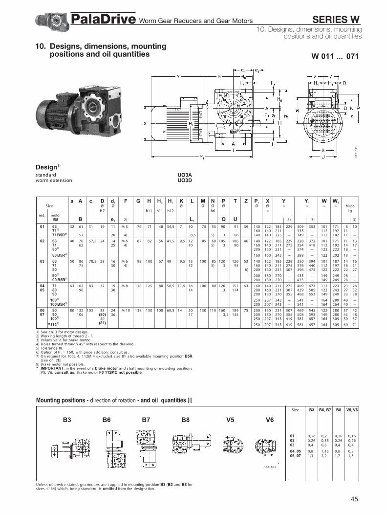
45
10. Designs, dimensions, mountingpositions and oil quantities
W 011 ... 071
UO3AUO3D
1) S ee c h. 3 for motor des ign.2) Working length of thread 2 · F.3) Values valid for brake motor.4) Holes turned through 45° with respec t to the drawing.5) Toleranc e t8.6) Option of P1 = 160, with pric e addition: c onsult us .7) On request for 100L 4, 112M 4 exc luded s ize 81 also available mounting pos ition B5R
(see c h. 2b).8) B rake motor not poss ible.* IMPORTANT: in the event of a brake motor and s haft mounting or mounting pos itions
V5, V6, consult us. B rake motor F0 112MC not possible.
a A c1 D d1 F G H H0 H1 K L M N P T Z P1 X Y Y1 W W1S ize Ø Ø Ø Ø Ø Ø Ø Ø ≈ ≈ ≈ ≈ Mass
H7 h11 h11 h12 h6 ≈ kgred. motor
B5 B e1 2) L1 Q U 3) 3) 3)
Unless otherwise stated, gearmotors are supplied in mounting pos ition B3 (B3 and B8 fors izes < 64) whic h, being standard, is omitted from the des ignation.
Mounting positions - direction of rotation - and oil quantities [l]
B3 B6, B7 B8 V5, V6S ize
01, 81 0,16 0,22 0,16 0,1602, 81 0,26 0,35 0,26 0,2603 , 81 0,46 0,62 0,42 0,42
04, 05 0,86 1,15 0,82 0,8206, 07 1,36 2,22 1,72 1,32
B3 B6 B7 B8 V5 V6
Design1)
s tandardworm extens ion
185 229 309 353 101 171 8 10211 – 335 – 112 192 11 –225 – 349 – 112 182 11 –
185 229 328 372 101 171 11 13211 275 354 418 112 192 14 17231 – 374 – 122 222 18 –
245 – 388 – 122 202 18 –
185 229 350 394 101 187 14 16211 275 376 440 112 197 18 21231 307 396 472 122 222 22 27
270 – 435 – 149 249 28 –270 – 435 – 149 249 28 –
211 275 409 473 112 223 23 26231 307 429 505 122 243 27 32270 355 468 553 149 249 33 38
343 – 541 – 164 289 40 –343 – 541 – 164 264 40 –
231 307 469 545 122 280 37 42270 355 508 593 149 280 43 48343 419 581 657 164 305 50 57
343 419 581 657 164 305 60 71
01 *163 32 61 51,5 19 11 M 50 76 71 48 34,5 7,5 10,5 75 55 190,5 91 39 140 122*1718)B5 19,5 160 140*171B5R8) 52 20 4) 8,5 5) 193,5 66 140 140
02 *163 40 70 57,5 24 14 M 60 87 82 56 41,5 9,5 12,5 85 68 105,5 106 46 140 122*1717 62 25 4) 10,5 5) 193,5 80 160 140*1808) ,5 200 160
*180 B5R8) ,5 160 160
03 *1634) 50 86 70,5 28 16 M 60 98 100 67 49,5 9,5 13,5 100 85 120,5 126 53 140 122*1717) 75 30 4) 12,5 5) 193,5 95 160 140*1807) 1,5 6) 200 160
*1908) 195 200 180*190 B5R8) 195 200 180
04 *1714) 63 102 83,5 32 19 M 80 118 125 80 58,5 11,5 16,5 100 80 120,5 151 63 160 14005 *1807) 90 30 14,5 193,5 114 200 160
*1907) 19,5 200 180
*1008) 250 207*100 B5R8) 19,5 200 207
06 *1804) 80 132 103,5 38 24 M 10 138 150 100 69,5 14,5 20,5 130 110 160,5 189 75 200 16007 *1907) 106 (80) 36 17,5 193,5 135 200 180
*1007) 40 195 250 207
*1127) (81) 19 250 207
UT.
C 6
91
UT.C 693
10. Designs, dimensions, mountingpositions and oil quantities
Worm Gear Reducers and Gear Motors SERIES WPalaDrive

46
Unless otherwise stated, gearmotors are supplied in mouting positions B3 which, beingstandard, is omitted from the designation.1) Sizes 13 and 14 in B7, mounting position with n1 > 710 min-1, carry a price addition.
W 081 ... 141
UO2A5)
a A c1 D d1 F G G0 G1 G2 H H0 H1 K L M N P T V0 ZS ize Ø Ø Ø Ø Ø Ø Ø
H7 h11 h11 h12 h6 maxred. motor
B5 B e1 2) Q U 08 *1907) 100 180 130 48 28 M 124 170 180 122 11 180 125 84,5 16 23 165 130 200,5 236 45 90
*1007) 131 42 203,5 165*1127)
*1327) 190
09 *1007) 125 225 155 60 32 M 128 205 221 148 15 225 150 99,5 18 28 215 180 250,5 287 50 106 10 *1127) 155 58 204,5 194
*1327)
*1606)
11 *1127) 160 272 187 70 38 M 148 247 255 178 15 280 180 118,5 22 33 265 230 300,5 345 60 125 12 *1327) 183 (160) 58 204,5 232
*1607)75 260
*1808) (161)
13 *1327) 200 342 235 90 48 M 168 292 324 222 20 335 225 137,5 27 40 300 250 350,5 431 80 150*1607) 214 82 305 205,5 270*1807)
*2007)
14 *1607) 250 425 287 110 55 M 208 360 379 277 20 410 280 163,5 33 50 400 350 450,5 537 80 180*1807) 250 82 3) 205,5 320*2007)
*2257) 370*2506)
P1 X Y Y1 W W1Ø Ø ≈ ≈ ≈ ≈ Mass
≈ kg
4) 4) 4)
200 180 270 355 620 705 149 325 62 67250 207 343 419 693 769 164 350 69 76250 207 343 445 693 795 164 350 79 90
300 260 402 537 772 907 196 375 104 115
250 207 343 419 769 845 164 400 103 110250 207 343 445 769 871 164 400 113 124300 260 402 537 828 963 196 425 143 159
300 315 540 – 966 – 235 425 173 –
250 207 343 445 845 947 164 465 172 183300 260 402 537 904 1039 196 490 203 219350 315 540 634 1055 1149 235 515 236 260
350 354 615 634 1130 1149 257 515 290 260
300 260 402 537 1018 1153 196 575 306 322350 315 540 634 1169 1263 235 600 339 363350 354 615 734 1244 1363 257 600 393 429
400 354 615 734 1244 1363 257 625 419 459
350 315 540 634 1279 1373 235 705 493 517350 354 615 734 1354 1473 257 705 547 583400 354 615 734 1354 1473 257 730 573 613
450 416 690 – 1439 – 292 755 633 –450 416 690 – 1439 – 292 755 667 –
Mounting positions - direction of rotation - and oil quantities [l]
B3 B6, B7 B8 V5, V6S ize
08, 081 1,9 5,4 4,2 3,5 09, 10 3,4 10,5 8,2 5,7 11, 12 5,6 18,5 15,5 10,5
13, 081 9,5 33,5 30,5 20,5 14, 081 17,3 57,5 51,5 34,5
B3 B6 B7 B8 V5 V61)
Design1)
s tandard
1) S ee c h. 3 for motor des ign.2) Working length of thread 2 · F.3) Holes turned through 22° 30’ with respec t to the drawing.4) Values valid for brake motor.5) Prearranged des ign for worm shaft extens ion (see c h. 2).6) Mounting pos ition B5R (see c h. 2b), brake motor not poss ible.7) On request for 132M 4 also available mouting pos ition B5R (see c h. 2b).8) B rake motor F0 180L not possible.* IMPORTANT: in the event of brake motor and s haft mounting or mounting pos itions V5,
V6, consult us. B rake motor F0 132MB not possible. For motor 200LG 4, X dimen-s ion increases by 73 mm, Y and Y1 dimensions increase by 110 mm and mass by 35 kg,brake motor not possible.
UT.
C 6
92
UT.C 700
08 09...14
10. Designs, dimensions, mountingpositions and oil quantities
Worm Gear Reducers and Gear Motors SERIES WPalaDrive

47
MW 012 ... 072
UO3AUO3D
1) S ee c h. 3 for motor des ign.2) Working length of thread 2 · F.3) Values valid for brake motor.4) Holes turned through 45° with respec t to the drawing.5) Toleranc e t8.6) Option of P1 = 160, with pric e addition: c onsult us .7) Mounting pos ition B5R (see c h. 2b); brake motor not poss ible.8) B rake motor F0 90LB and 90LC not possible.
a A c1 D d1 F G H H0 H1 K L M N P T Z P1 X Y Y1 W W1S ize Ø Ø Ø Ø Ø Ø Ø Ø ≈ ≈ ≈ ≈ Mass
H7 h11 h11 h12 h6 ≈ kgred. motor
B5 a1 B e1 2) L1 Q U 3) 3) 3)
Unless otherwise stated, gearmotors are supplied in mounting pos ition B3 (B3 and B8 fors izes 64) whic h, being standard, is omitted from the des ignation.
Mounting positions - direction of rotation - and oil quantities [l]
B3 B6, B7 B8 V5, V6S ize
01, 81 0,26 0,25 0,26 0,2602, 81 0,32 0,45 0,32 0,3203, 81 0,56 0,72 0,52 0,52
04, 05 1,86 1,30 1,82 1,8206, 07 1,56 2,52 2,82 1,52
UT.C 696
B3 B6 B7 B8 V5 V6
Design1)
s tandard
worm extens ion
185 229 309 353 101 172 8 10
185 229 328 372 101 183 11 13211 275 354 418 112 194 14 17
185 229 350 394 101 191 14 16211 275 376 440 112 202 18 21231 307 396 472 122 222 22 27
211 275 409 473 112 224 23 26231 307 429 505 122 234 27 32270 355 468 553 149 261 33 38
211 275 449 513 112 250 33 36231 307 469 545 122 250 37 42270 355 508 593 149 269 43 48
343 – 581 – 164 284 50 –
01 1634) 32 61 51,5 19 11 M 50 76 71 48 34,5 7,5 10,5 75 55 190,5 91 39 140 122*1 32 52 20 4) 8,5 5) 193,5 66
02 1634) 40 70 57,5 24 14 M 60 87 82 56 41,5 9,5 12,5 85 68 105,5 106 46 140 1221717) 40 62 25 4) 10,5 5) ,3 80 160 140
03 1634) 50 86 70,5 28 16 M 60 98 100 67 49,5 9,5 13,5 100 85 120,5 126 53 140 1221717) 40 75 30 4) 12,5 5) 193,5 95 160 1401807) 1,5 6) 200 160
04 1714) 63 102 83,5 32 19 M 80 118 125 80 58,5 11,5 16,5 100 80 120,5 151 63 160 14005 1807) 50 90 30 14,5 193,5 114 200 160
1908) 19,5 200 180
06 1714) 80 132 103,5 38 24 M 10 138 150 100 69,5 14,5 20,5 130 110 160,5 189 75 160 14007 1807) 50 106 (80) 36 17,5 193,5 135 200 160
1907) 40 195 200 180
1007) (81) 19 200 207
UT.
C 6
94
<
10. Designs, dimensions, mountingpositions and oil quantities
Worm Gear Reducers and Gear Motors SERIES WPalaDrive

48
Unless otherwise stated, gearmotors are supplied in mouting positions B3 which, beingstandard, is omitted from the designation.1) Sizes 08 ... 14 in mounting position B6 carry a price addition.
MW 082 ... MW 142
UO2A5)
a A c1 D d1 F G G0 G1 G2 H H0 H1 K L M N P T V0 ZS ize Ø Ø Ø Ø Ø Ø Ø
H7 h11 h11 h12 h6 maxred. motor
B5 a1 B e1 2) Q U
P1 X Y Y1 W W1Ø Ø ≈ ≈ ≈ ≈ Mass
≈ kg
4) 4) 4)
200 160 231 307 581 657 122 305 57 62200 180 270 355 620 705 149 305 63 68250 207 343 419 693 769 164 307 70 77
250 207 343 445 693 795 164 307 80 91
200 180 270 355 696 781 149 375 98 103250 207 343 419 769 845 164 375 105 112250 207 343 445 769 871 164 375 115 126
300 260 402 537 828 963 196 376 145 161
250 207 343 419 845 921 164 460 165 172250 207 343 445 845 947 164 460 175 186300 260 402 537 904 1039 196 460 206 222
350 315 540 634 1055 1149 235 460 239 263350 315 540 – 1055 – 235 460 271 –
250 207 343 419 959 1035 164 560 272 279250 207 343 445 959 1061 164 560 282 293300 260 402 537 1018 1153 196 560 310 326
350 315 540 634 1169 1263 235 560 343 367350 354 615 734 1244 1363 257 560 397 433350 354 615 – 1244 – 257 560 423 –
300 260 402 537 1141 1276 196 690 466 482350 315 540 634 1279 1373 235 690 499 523350 354 615 734 1354 1473 257 690 553 589
400 354 615 734 1354 1473 257 690 579 619450 416 690 – 1439 – 292 690 639 –
Mounting positions - direction of rotation - and oil quantities [l]
B3 B6, B7 B8 V5, V6S ize
08, 081 2,1 6,3 4,5 3,3 09, 10 3,8 11,6 8,8 6,3 11, 12 6,5 20,8 16,5 11,2
13, 081 10,4 38,5 31,5 21,2 14, 081 18,3 67,5 53,5 35,7
B3 B6 B7 B8 V5 V61)
Design1)
s tandard
1) S ee c h. 3 for motor des ign.2) Working length of thread 2 · F.3) Holes turned through 22° 30’ with respec t to the drawing.4) Values valid for brake motor.5) Prearranged des ign for worm shaft extens ion (see c h. 2).6) Mounting pos ition B5R (see c h. 2b), brake motor not poss ible.7) B rake motor not poss ible.8) B rake motor F0 132MC not possible.
08 1807) 100 180 130 48 28 M 124) 170 180 122 11 180 125 84,5 16 23 165 130 200,5 236 45 90907) 63 131 42 203,5 165
1007)
1127)
09 907) 125 225 155 60 32 M 128 205 221 148 15 225 150 99,5 18 28 215 180 250,5 287 50 106 10 1007) 80 155 58 204,5 194
1127)
1328)
11 1007) 160 272 187 70 38 M 148 247 255 178 15 280 180 118,5 22 33 265 230 300,5 345 60 125 12 1127) 100 183 (160) 58 204,5 232
1327)75
1607) (161) 260 20,5180M7)
13 1007) 200 342 235 90 48 M 168 292 324 222 20 335 225 137,5 27 40 300 250 350,5 431 80 1501127) 100 214 82 205,5 2701327)
1607) 305 20,51807) 20,52006)
14 1327) 250 425 287 110 55 M 208 360 379 277 20 410 280 163,5 33 50 400 350 450,5 537 80 1801607) 125 250 82 3) 205,5 3201807)
2007)
2256) 370
UT.
C 6
95
UT.C 701
08 09 ... 14
10. Designs, dimensions, mountingpositions and oil quantities
Worm Gear Reducers and Gear Motors SERIES WPalaDrive
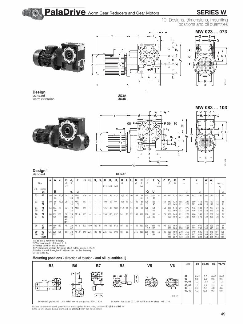
49
Unless otherwise stated, gearmotors are supplied in mounting position B3 (B3 and B8 forsizes 64) which, being standard, is omitted from the designation.
MW 023 ... 073
MW 083 ... 103
UO3AUO3D
UO2A4)
1) S ee c h. 3 for motor des ign.2) Working length of thread 2 · F.3) Values valid for brake motor.4) Prearranged des ign for worm shaft extens ion (see c h. 2).5) Holes turned through 45° with respec t to the drawing.6) Toleranc e t8.
a A c1 D d1 F G G0 G1 G2 H H0 H1 K L L1 M N P T V0 Z P1 X Y Y1 W W1S ize Ø Ø Ø Ø Ø Ø Ø Ø Ø ≈ ≈ ≈ ≈ Mass
H7 h11 h11 h12 h6 max kgred. motor
B5 B e1 2) Q U 3) 3) 3)
Mounting positions - direction of rotation - and oil quantities [l]
B3 B6, B7 B8 V5, V6S ize
02, 081 0,42 0,52 0,42 0,4203, 801 0,66 0,85 0,60 0,6004, 050 1,26 1,552 1,22 1,22
06, 070 1,76 2,85 2,32 1,82 08 ,126 2,46 6,82 4,82 3,62 09, 10 4,26 12,82 9,32 6,82
B3 B6 B7 B8 V5 V6
Design 1)
s tandardworm extens ion
Design1)
s tandard
122 185 229 347 391 101 171 11 13
122 185 229 369 413 101 187 14 16140 211 275 395 459 112 197 18 21
140 211 275 436 500 112 223 24 27160 231 307 456 532 122 243 28 33
140 211 275 476 540 112 260 34 37160 231 307 496 572 122 280 38 43
160 231 307 614 690 122 325 59 64180 270 355 653 738 149 325 65 70
180 270 355 740 825 149 375 101 106207 343 419 813 889 164 400 108 115207 343 419 813 889 164 400 114 123
02 63M 40 70 57,5 24 14 M 62 8 106 – – – 82 56 41,5 9,5 12 10 85 68 105,5 106 – 46 14062 25 5) 6) 3,5 80
03 63M 50 86 70,5 28 16 M 62 8 117 – – – 100 67 49,5 9,5 13 12 100 85 120,5 126 – 53 14071M 75 30 5) 6) 3,5 95 160
04 71M 63 102 83,5 32 19 M 82 8 145 – – – 125 80 58,5 11,5 16 14 100 80 120,5 151 – 63 16005 80M 90 30 3,5 114 200
06 71M 80 132 103,5 38 24 M 10 8 165 – – – 150 100 69,5 14,5 20 17 130 110 160,5 189 – 75 16007 80M 106 (80) 36 3,5 135 200
40(81)
08 80M 100 180 130,5 48 28 M 12 8 203 180 122 11 180 125 84,5 16,5 23 – 165 130 200,5 236 45 90 20090M 131 42 3,5 165 200
09 90M 125 225 155,5 60 32 M 12 8 249 221 148 15 225 150 99,5 18,5 28 – 215 180 250,5 287 50 106 200 10 100M 155 58 4 194 250
112M 250
S c hemi di grand. 40 .. . 81 validi anc he per grand. 100 .. . 126. S c hemes for s izes 02 ... 07 valid also for s izes 08 .. . 10.
UT.
C 6
97
UT.
C 6
98
UT.C 699
08 09 , 10
10. Designs, dimensions, mountingpositions and oil quantities
Worm Gear Reducers and Gear Motors SERIES WPalaDrive
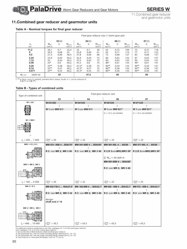
50
Table A - Nominal torques for final gear reducer
Table B - Types of combined units
Final gear reduc er s ize / i worm gear pair
03/20 04/25 06/25 07/25n2 MN2 M2max MN2 M2max MN2 M2max MN2 M2max
min-1 daN m daN m daN m daN m daN m daN m daN m daN m
11,2 20,1 0,7 33,4 32 0,7 58 63 0,72 109 75 0,72 1189 20,5 0,68 35 33,8 0,69 61 65 0,71 113 77 0,71 1234,5 21,3 0,66 38,4 37,8 0,66 68 72 0,68 127 82 0,68 137
2,24 23,9 0,64 40,2 42,9 0,64 73 80 0,65 133 87 0,65 1411,12 25 0,62 40,2 47,5 0,62 73 80 0,63 133 90 0,63 1410,56 25* 0,6 40,2 47,5 0,6 73 80* 0,61 133 90* 0,61 141
0,28 25** 0,58 40,2 47,5* 0,58 73 80** 0,59 133 90** 0,59 1410,14 25** 0,57 40,2 47,5* 0,57 73 80** 0,58 133 90** 0,58 1410,071 25** 0,55 40,2 47,5* 0,55 73 80** 0,56 133 90** 0,56 141
M2 [daN m] 25 47,5 80 90S ize
*, ** In these c ases fs required, provided that it always results 1, c an be reduc ed of1,12 (*) or 1,18 (**).
Type of c ombined unitFinal gear reduc er s ize
03 04 06 07
For initial gear reduc er performanc e see: this c atalogue c h. 7 or 9 for worm gear reduc er,and c atalogue E c h. 6 or 8 for c oaxial gear reduc er.1) An anc hor link is fitted between initial and final gear reduc er.2) The gearmotor has 140 mm motor mounting flange (dimension P 0, c h. 12).3) The gearmotor has 160 mm motor mounting flange (dimension P0, c h. 12).4) G ear reduc er in « overs ized B 5 flange» (see c h. 17 c at. E ).
W 1 + W 1
+ + + +
+ + + +
+ + + +
5) i = 63 is not admitted. 5) i = 63 is not admitted.
W 1 + MW 1
1)
iN ≈ 250 .. . 1 600 i = 20 i = 25 i = 25 i = 25
MW 1 + R 2, R 3
MN2 60 daN m
MW 1 + MR 2, MR 3 +
iN ≈ 160 .. . 4 000 i = 20 i = 25 i = 25 i = 25
MW 2 + R 2
design:shaft end Ø 14
MW 2 + MR 2, MR 3
iN ≈ 400 .. . 10 000 i = 50,7 i = 63,5 i = 63,5 i = 63,5finalefinal
finalefinal
finalefinal
finalefinal
R 2 o/or MR 2, MR 3 40R 2 o/or MR 2, MR 3 40R 2 o/or MR 2, MR 3 40R 2 o/or MR 2, MR 3 32
MW 072 - 80B 4 ... B5A/22,13)MW 062 - 80B 4 ... B5A/22,13)MW 042-80B 4 ... B5A/22,13)MW 032-71B 4 ... B5A/27,62)
finalefinal
finalefinal
finalefinal
finalefinal
R 2 o/or MR 2, MR 3 40
MW 061-80B 4 ... B5A/563)
perfor
R 2,R 3 o/or MR2,MR3 504)R 2,R 3 o/or MR2,MR3 504)R 2 o/or MR 2, MR 3 40R 2 o/or MR 2, MR 3 40
MW 071-90L 4 ... B5/56MW 061-90L 4 ... B5/56MW 041-80B 4 ... B5A/563)MW 031- 80B 4 ...B5A/703)
finalefinal
finalefinal
finalefinal
finalefinal
W 1 o/or MW 0215)W 1 o/or MW 0215)W 1 o/or MW 011W 1 o/or MW 011
W 0 71/25W 0 61/25W 0 41/25W 031/20
11.Combined gear reducerand gearmotor units
11.Combined gear reducer and gearmotor units
Worm Gear Reducers and Gear Motors SERIES WPalaDrive

51
Tabella B - Tipi di gruppi Table B - Types of combined units
Final gear reduc er s ize / i worm gear pair
08/25 09/32 11/32n2 MN2 M2max MN2 M2max MN2 M2max
min-1 daN m daN m daN m daN m daN m daN m
11,2 129 0,74 215 200 0,74 339 372 0,76 6369 133 0,73 229 208 0,73 361 391 0,75 6804,5 145 0,69 257 230 0,69 413 435 0,71 784
2,24 154 0,67 268 254 0,66 458 494 0,68 8501,12 160 0,65 268 279 0,64 468 500 0,65 8500,56 160* 0,63 268 300 0,61 468 500* 0,63 850
0,28 160** 0,61 268 300* 0,6 468 500** 0,61 8500,14 160** 0,59 268 300* 0,58 468 500** 0,59 8500,071 160** 0,57 268 300* 0,56 468 500** 0,57 850
M2 [daN m] 160 300 500S ize
*, ** In these c ases fs required, provided that it always results 1, c an be reduc ed of1,12 (*) or 1,18 (**).
Type of c ombined unit Final gear reduc er s ize
08 09 11
For initial gear reduc er performanc e see: this c atalogue c h. 7 or 9 for worm gear reduc er,and c atalogue E c h. 6 or 8 for c oaxial gear reduc er.1) An anc hor link is fitted between initial and final gear reduc er.4) G ear reduc er in « overs ized B 5 flange» (see c h. 17 c at. E ); s ize 63 has a low speed shaft
reduc ed to 28 mm: « overs ized B 5 flange - Ø 28» .5) The gearmotor has 250 mm motor mounting flange (dimension P0, c h. 12).6) The gearmotor has 300 mm motor mounting flange (dimension P0, c h. 12).7) The gearmotor has 350 mm motor mounting flange (dimension P0, c h. 12).
W 1 + W 1 W 1 + W 2
W 1 + MW 1 W 1 + MW 2
1)
iN ≈ 315 .. . 8 000 i = 25 i = 32 i = 32
MW 1 + R 2, R 3
MN2 112 daN m MN2 400 daN m
MW 1 + MR 2, MR 3
MN2 315 daN m
+
iN ≈ 200 .. . 5 000 i = 25 i = 32 i = 32
MW 2 + R 2, R 3
MW 2 + MR 2, MR 3
iN ≈ 500 .. . 12 500 i = 63,5 i = 81,1 i = 102finalefinal
finalefinal
finalefinal
R 2,R 3 o/or MR 2, MR 3 634)R 2,R 3 o/or MR 2, MR 3 634)R 2,R 3 o/or MR 2, MR 3 504)
MW 112-112M 4 ... B5/13,8MW 092-112M 4 ... B5/17,3MW 082-90L 4 ... B5/22,1
finalefinal
finalefinal
finalefinal
R 2,R 3 o/or MR 2, MR 3 63 4)
MW 111-112M 4 ... B5/43,8
perfor
R 2,R 3 o/or MR 2, MR 3 64 4)R 2,R 3 o/or MR 2, MR 3 50 4)
MW 111-132MB 4 ...B5A/43,85)MW 081-90L 4 ... B5/56
perfor
perfor
R 2,R 3 o/or MR 2, MR 3 80 4)R 2,R 3 o/or MR 2, MR 3 63 4)R 2,R 3 o/or MR 2, MR 634)
MW 111-132MB 4 ... B5/43,8MW 091-112M 4 ... B5/43,8MW 081-100LB 4 ... B5/56
finalefinal
finalefinal
finalefinal
W 1, W 2 o/or MW 1 , MW 032 W 1, W 2 o/or MW 1 , MW 042 W 1, W 2 o/or MW 1 , MW 062
W 081/25 W 091/32 W 111/32+ + +
+ + +
+ + +
+ +
11.Combined gear reducerand gearmotor units
Table B - Types of combined units
Table A - Nominal torques for final gear reducer
Worm Gear Reducers and Gear Motors SERIES WPalaDrive

52
Table B - Types of combined units
Final gear reduc er s ize / i worm gear pair
12/32 13/32 14/40n2 MN2 M2max MN2 M2max MN2 M2max
min-1 daN m daN m daN m daN m daN m daN m
11,2 442 0,76 691 730 0,78 1 201 1 190 0,79 2 0139 466 0,75 739 767 0,77 1 258 1 270 0,78 2 0724,5 516 0,71 851 851 0,73 1 487 1 440 0,73 2 467
2,24 556 0,68 921 923 0,69 1 662 1 562 0,69 2 8121,12 560 0,65 921 1 000 0,67 1 736 1 704 0,66 3 0340,56 560* 0,63 921 1 000* 0,64 1 736 1 900 0,64 3 134
0,28 560** 0,61 921 1 000** 0,63 1 736 1 900* 0,61 3 1340,14 560** 0,59 921 1 000** 0,61 1 736 1 900** 0,60 3 1340,071 560** 0,57 921 1 000** 0,58 1 736 1 900** 0,57 3 134
M2 [daN m] 560 1 000 1 900S ize
Type of c ombined unit Final gear reduc er s ize
12 13 14W 1 + W 1 W 1 + W 2
+ + +
+ + +
+ + +
+ +
W 1 + MW 1 W 1 + MW 2
1)
iN ≈ 315 .. . 10 000 i = 32 i = 32 i = 40
MW 1 + R 2, R 3
MN2 400 daN m MN2 800 daN m MN2 1 400 daN m
MW 1 + MR 2, MR 3
MN2 670 daN m
+
iN ≈ 200 .. . 6 300 i = 32 i = 32 i = 40
MW 2 + R 2, R 3
MW 2 + MR 2, MR 3
iN ≈ 500 .. . 16 000 i = 102 i = 81,8 i = 102finalefinal
finalefinal
finalefinal
R 2,R 3 o/or MR 2, MR 3 1004)R 2,R 3 o/or MR 2, MR 3 804)R 2,R 3 o/or MR 2, MR 3 634)
MW 142-180L 4 ... B5/13,7MW 132-132MB 4 ... B5/17,1MW 122-112M 4 ... B5/13,8
finalefinal
finalefinal
finalefinal
R 2,R 3 o/or MR 2, MR 3 80 4)
MW 151-132MB 4 ... B5/43,8
perfor
R 2,R 3 o/or MW 2, MR 3 100 4)R 2, R 3 o/or MR 2, MR 3 814)R 2,R 3 o/or MR 2, MR 3 64 4)
MW 141-180L 4 ... B5/35MW 131-180L 4 ... B5A/43,8 6)MW 121-132MB 4 ... B5A/43,85)
perfor
perfor
perfor
R 2,R 3 o/or MR 2, MR 3 101 4)R 2,R 3 o/or MR 2, MR 3 100 4)R 2,R 3 o/or MR 2, MR 3 80 4)
MW 141-200L 4 ... B5A/357)MW 131-180L 4 ... B5/43,8MW 121-132MB 4 ... B5/43,8
finalefinal
finalefinal
finalefinal
W 1,W 2 o/or MW 1,MW 062 W 1,W 2 o/or MW 1,MW 082
W 121/32 W 131/32
W 1,W 2 o/or MW 1,MW 092
W 141/40
< <
<
<
11.Combined gear reducerand gearmotor units
Table B - Types of combined units
Table A - Nominal torques for final gear reducer
Worm Gear Reducers and Gear Motors SERIES WPalaDrive

53
1) See relevant catalogues for design, mounting position and oil quantities of single gearreducers.
2) The coupling position of the initial gear reducer with respect to the final one should bedescribed in detail, though only in the case of 1, 2 or 3.Important: personal safety-guards are the Buyer’s responsibility (98/37/EC).
MW 1 ...+ MR 2, MR 3 ...
MW 2 ... + MR 2, MR 3 ...
W 1 ... + MW 2 ... 2)
MW 1 ...+ MR 2, MR 3 ...
MW 2 ... + MR 2, MR 3 ...
Final gear reducer size
08 ... 14
W 1 ...+ MW 1 ...2)
Final gear reducer size
03 ... 07W 1 ...+ MW 1 ...2)
12. Combined unit dimensions1) (gearmotors)
12. Combined unit dimensions1) (gearmotors)
Worm Gear Reducers and Gear Motors SERIES WPalaDrive

54
S ize
gear reduc er mot.
B5final initial
a a1 A c1 D d1 F G H H1 K M N O P P0 P1 T W1 Z X Y Y1 WØ Ø h11 h12 Ø Ø Ø 5 Ø Ø Ø Ø Mass
H7 h6≈ ≈ ≈
≈ kg
a0 a2 B e1 1) H0 L1 G0 Q U Z1
h11 L1 6) 6) 6)
03 W-1 MW-011 32
04 W-1 MW-011 32
MW-1 MR2, MR3 40
MW-2 MR2, MR3 32
W-1 63
50 40 86 70,5 28 16 M 648 76 100 49,5 9,5 100 85 116 120,5 – 140 126 1835) 53 122 185 229 253 253 101 17 19
63
63
MW-1 MR2, MR3 40
MR2, MR3 50
63
32 – 75 30 2)48 211
67 ,5 13,5 4) – 3,5160 140
952045) 39
122 185 229 463 507 101 22 2471 12,5
160 5) 140 211 275 489 553 112 25 28
63
MW-2 710607
W-1 MW-021 40 6371
08 W-1 MW-031 50
MW-1 MR2, MR3 63
MW-1MW-2
MR2, MR3 63
MW-011 MR2, MR3 80
MW-012 MR2, MR3 63
MW-1 MR2, MR3 100
MW-2 MR2, MR3 80
MR2, MR3 8081
MR2, MR3 6364
MR2, MR3 50
MR2, MR3 50
MW-032 50637180
09 W-1 MW-041 63MW-042 63
718090
1112
W-1 MW-061 80
13 W-1 MW-081 100
14 W-1 MW-091 125MW-092 125
MW-1MW-2
MR2, MR3 100101
MW-082 100
MW-062 8071809090
MR2, MR3 40 6371
71
7180
MW-1 63
MR2, MR3 40MW-2 63
186 140 140 1915) 5) 122 185 229 438 482 101 20 22
63 50 102 83,5 32 19 M 848 76 125 58,5 11,5 100 80 129 120,5 – 140 151 2055) 63 122 185 229 279 279 101 22 2432 – 90 30
48 23180 ,5 16,5 – 3,5
160 140114
2305) 39122 185 229 496 540 101 27 2914,5
160 2245) 5) 140 211 275 522 586 112 30 33
80 50 132 103,5 38 24 M 108 87 150 69,5 14,5 130 110 153 160,5 – 140 189 2505) 75 122 185 229 323 323 101 35 3740 – 106 (80) 36 48 100 ,5 20,5 – 3,5 160 135 5) 46 140 211 275 333 333 112 38 41
40 28217,5
200 140 2865) 5) 122 185 229 567 611 101 43 45(81) 48 ,5 ,5 160 5) 140 211 275 593 657 112 47 50
48 ,5 ,5 200 5) 160 231 307 613 689 122 51 56
251,5
160 140 2675) 5) 122 185 229 536 580 101 37 3948 ,5 ,5 160 5) 140 211 275 562 626 112 40 43
251,5
160 140 2505) 5) 122 185 229 536 580 101 37 3948 ,5 ,5 160 5) 140 211 275 562 626 112 40 43
100 63 180 130,5 48 28 M 128 98 180 84,5 16,5 165 130 187 200,5 – 140 236 3055) 90 122 185 229 429 429 101 58 6050 40 131 42 48 125 ,5 23,5 – 3,5 160 165 5) 53 140 211 275 439 439 112 62 65
48 ,5 ,–5 200 5) 160 231 307 459 459 122 66 71
71 347,5
250 160 3575) 5) 140 211 275 730 794 112 74 7780 48 ,5 ,5 200 5) 160 231 307 750 826 122 78 8390 48 ,5 ,5 200 5) 180 270 355 789 874 149 84 89
63 314,5
200 140 3315) 5) 122 185 229 671 715 101 63 6571 48 ,5 ,5 160 5) 140 211 275 697 761 112 67 7080 48 ,5 ,5 200 5) 160 231 307 717 793 122 71 76
63 314,5
200 140 3055) 5) 122 185 229 671 715 101 63 6571 48 ,5 ,5 160 5) 140 211 275 697 761 112 67 7080 48 ,5 ,5 200 5) 160 231 307 717 793 122 71 76
125 80 225 155,5 60 32 M 128 118 225 99,5 18,5 215 180 222 250,5 – 160 287 3755) 106 140 211 275 515 515 112 97 10063 50 155 58 48 150 ,5 28,5 – 4,5 200 194 5) 63 160 231 307 535 535 122 101 106
48 ,5 ,–5 200 5) 180 270 355 535 535 149 107 112
71 382,5
250 160 4075) 5) 140 211 275 806 870 112 110 11380 48 ,5 ,5 200 3755) 160 231 307 826 902 122 114 11990 48 ,5 ,5 200 5) 180 270 355 865 950 149 120 125
100 48 ,5 ,5 250 5) 207 343 419 938 1014 164 127 134
160 100 272 187,5 70 38 M 148 138 280 118,5 22,5 265 230 268 300,5 – 160 345 4605) 125 140 211 275 593 593 112 163 16680 50 183 (160) 58 48 180 ,5 33,5 – 4,5 200 232 5) 75 160 231 307 613 613 122 167 172
48 ,5 ,–5 200 5) 180 270 355 613 613 149 173 17875 48 ,5 ,5 250 5) 207 343 419 638 638 164 180 187
80(161)
466 ,5 300 200 5005) 5) 160 231 307 942 1018 122 188 19390 48 ,5 ,5 200 5) 180 270 355 981 1066 149 194 199
100 ,5 250 5) 5) 207 343 419 1054 1130 164 201 208112 ,5 250 5) 5) 207 343 445 1054 1156 164 211 222132 469 ,5 300 5) 5) 260 402 537 1116 1251 196 240 256
71 424 ,5 250 160 4725) 5) 140 211 275 880 944 112 167 17080 ,5 200 5) 5) 160 231 307 900 976 122 171 17690 ,5 200 5) 5) 180 270 355 939 1024 149 177 182
100 ,5 250 5) 5) 207 343 419 1012 1088 164 184 191112 ,5 250 5) 5) 207 343 445 1012 1114 164 194 205
71 424,5
250 160 4605) 5) 140 211 275 880 944 112 170 17380 ,5 200 5) 5) 160 231 307 900 976 122 174 17990 ,5 200 5) 5) 180 270 355 939 1024 149 180 185
100 ,5 250 5) 5) 207 343 419 1012 1088 164 187 194
100 200 100 342 235,5 90 48 M 168 170 335 137,5 27,5 300 250 328 350,5 – 200 431 5605) 150 160 231 307 745 745 122 290 29590 100 63 214 82 48 225 ,5 40,5 180 5,5 200 270 5) 90 180 270 355 745 745 149 296 301
100 48 ,5 ,–5 250 5) 207 343 419 770 770 164 303 310112 48 ,5 ,5 250 5) 207 343 445 770 770 164 313 324
90 574 ,5 350 200 6205) 5) 180 270 355 1161 1246 149 327 332100 ,5 250 5) 5) 207 343 419 1234 1310 164 334 341112 ,5 250 5) 5) 207 343 445 1234 1336 164 344 355132 ,5 300 5) 5) 260 402 537 1293 1428 196 374 390
80 511 ,5 300 200 5855) 5) 160 231 307 1059 1135 122 291 29690 ,5 200 5) 5) 180 270 355 1098 1183 149 297 302
100 ,5 250 5) 5) 207 343 419 1171 1247 164 304 311112 ,5 250 5) 5) 207 343 445 1171 1273 164 314 325132 514 ,5 300 5) 5) 260 402 537 1233 1368 196 344 360
80 511 ,5 300 200 5605) 5) 160 231 307 1059 1135 122 295 30090 ,5 200 5) 5) 180 270 355 1098 1183 149 301 306
100 ,5 250 5) 5) 207 343 419 1171 1247 164 308 315112 ,5 250 5) 5) 207 343 445 1171 1273 164 318 329
90 250 125 425 287,5 110 55 M 168 205 410 163,5 33,5 400 350 401 450,5 – 200 537 6905) 180 180 270 355 876 876 149 480 485100 125 80 250 82 3) 280 ,5 50,5 221 5,5 250 320 5) 106 207 343 419 895 895 164 487 494112 48 ,5 ,–5 250 5) 207 343 445 895 895 164 497 508132 48 ,5 ,5 300 5) 260 402 537 920 920 196 527 543
90 629 ,5 350 200 7255) 5) 180 270 355 1268 1353 149 484 489100 ,5 250 6905) 5) 207 343 419 1341 1417 164 491 498112 ,5 250 5) 5) 207 343 445 1341 1443 164 501 512132 ,5 300 5) 5) 267 402 537 1400 1535 196 531 547160 645 ,5 350 5) 5) 315 540 634 1554 1648 235 564 588
1) Working length of thread 2 · F.2) Holes turned through 45° with respec t to the drawing.3) Holes turned through 22° 30’ with respec t to the drawing.4) Toleranc e t8.5) Highest value is valid for MW-16) Values valid for brake motor.
12. Combined unit dimensions1) (gearmotors)
Worm Gear Reducers and Gear Motors SERIES WPalaDrive

55
* This s tandard mounting pos ition must not be stated in the des ignation.1) G reas e quantity is the s ame fores een for B 3 mounting pos ition of c at. E .
On name plate there is a * in c orres pondenc e of mounting pos ition.
C ouplingposition
–
1
2
3
- Final gear reduc er mounting pos ition
B3 B6 B7 B8 V5 V6
Initial gearmotor mounting pos ition
W 1 ... + MW 1... W 1 ... + MW 2...
W 1 ... + MW 1... W 1 ... + MW 2...
W 1 ... + MW 1... W 1 ... + MW 2...
W 1 ... + MW 1... W 1 ... + MW 2...
MW 1 ... + R 2, R 3 ... MW 2 ... + R 2, R 3 ...
Initial gear reducer or gearmotor mounting positionIn order to make eas ier the individualization of the c ombined gearreduc er and gearmotor mounting pos ition refer to following tablewhere, ac c ording to the final gear reduc er mounting pos ition and tothe initial gear reduc er or gearmotor c oupling pos ition, the mountingpositions of the same initial gear reduc er or gearmotor are s tated.
12. Combined unit dimensions1) (gearmotors)Worm Gear Reducers and Gear Motors SERIES WPalaDrive

56
13. Radial loads1) Fr1 [daN] on
high speed shaft end14. Radial loads F
r2 [daN] or axial loads F
a2[daN] on low speed shaft end
R adial loads generated on the shaft end by a drive c onnec ting gearreduc er and motor must be less than or equal to those given in therelevant table.The radial load F r1 given by the following formula refers to most c om-mon drives :
F r1 = [daN] for timing belt drive
F r1 = [daN] for V-belt drive
where: P 1 [kW] is power required at the input s ide of the gearreduc er, n1 [min-1] is the speed, d [m] is the pitc h diameter.
R adial loads given in the table are valid for overhung loads on c en-tre line of high speed shaft end, i.e. operating at a distanc e of 0,5 · e(e = shaft end length) from the shoulder. If they operate at 0,315 · emultiply by 1,25; if they operate at 0,8 · e multiply by 0,8.
4 775 · P1
d · n1
2 865 · P1
d · n1
14 - Radial loads Fr2 [daN] or axial loads Fa2
[daN] on low speed shaft end
Axial loads Fa2
Permiss ible Fa2 is shown in the c olumn where direc tion of rotation oflow speed shaft (blac k or white arrow) and direc tion of the axialforc e (solid or broken arrow) c orrespond to those of the gear reduc -er in question. Direc tion of rotation and direc tion of forc e may beestablished viewing the gear reduc er from any point, providing thesame point adopted for both.Wherever poss ible, c hoose the load c onditions c orresponding thec olumn on the right.
Radial loads F r2
R adial loads generated on the shaft end by a drive connecting gearreducer and machine must be less than or equal to those given inthe relevant table.
Normally, radial loads on low speed shaft ends are c ons iderable: infac t there is a tendenc y to c onnec t the gear reduc er to the mac hineby means of a transmiss ion with high transmiss ion ratio (economiz-ing on the gear reduc er) and with small diameters (ec onomizing onthe drive, and for requirements dic tated by overall dimensions).B earing life and wear (whic h also affec t gears unfavourably) and lowspeed shaft s trength, c learly impose limits on permiss ible radialload.
The high value whic h radial load may take on, and the importanc eof not exc eeding permiss ible values , make it nec essary to take fulladvantage of the gear reduc er’s poss ibilities .Permiss ible radial loads given in the table are therefore based on:the produc t of speed n2 [min-1] multiplied by bearing life Lh [h]required, the direc tion of rotation, the angular pos ition [°] of theload and torque M2 [daN m] required.
R adial loads given in the table are valid for overhung loads on c en-tre line of low speed shaft end, i.e. operating at a distanc e of 0,5 · E(E = shaft end length) from the shoulder. If operating at 0,315 · Emultiply by 1,25; if operating at 0,8 · E multiply by 0,8.
1) An axial load of up to 0,2 times the value in the table is permis s ible, s imultaneous lywith the radial load. If exc eeded c ons ult us .
n1
min-1
G randezza riduttore - G ear reduc er s ize
01 02 03 04, 05 06, 07 08 09, 10 11,12 13 14W 1 W 2 W 1 W 2 W 1 W 2 W 1 W 2 W 1 W 2 W 1 W 2 W 1 W 2 W 1 W 2 W 1 W 2 W 1 W 2
1 400 14 11,2 21,2 17 31,5 17 47,5 26,5 71 26,5 106 42,5 160 75 236 170 265 170 375 2501 120 15 11,8 22,4 18 33,5 18 50 28 75 28 112 45 170 80 250 180 280 180 400 265
900 16 12,5 23,6 19 35,5 19 53 30 80 30 118 47,5 180 85 265 190 300 190 425 280
710 18 14 26,5 21,2 40 21,2 60 33,5 90 33,5 132 53 200 95 300 212 335 212 475 315560 19 15 28 22,4 42,5 22,4 63 35,5 95 35,5 140 56 212 100 315 224 355 224 500 335450 20 16 30 23,6 45 23,6 67 37,5 100 37,5 150 60 224 106 335 236 375 236 530 355
355 22,4 18 33,5 26,5 50 26,5 75 42,5 112 42,5 170 67 250 118 375 265 425 265 600 400
13. Radial loads1) Fr1 [daN] on high speed shaft end
Worm Gear Reducers and Gear Motors SERIES WPalaDrive

57
14. Radial loads Fr2 [daN] or axial loads Fa2[daN] on low speed shaft end
R adial load F r2 for most c ommon drives has the following value andangular pos ition:
where: P2 [kW] is power required at the output s ide of the gear re-duc er, n2 [min-1] is the speed, d [m] is the pitc h diameter.
IMPORTANT: 0° c oinc ides with a half line lying parallel to the wormaxis , and oriented as shown above, and therefore it follows the rota-tion of the worm axis as shown below.
F r2 = [daN]
for c hain drive (lifting in general); fortiming belt drive replac e 1 910 with2 865
1 910 · P2
d · n2
F r2 = [daN]
for V-belt drive
4 775 · P2
d · n2
F r2 = [daN]
for spur gear pair drive
2 032 · P2
d · n2
F r2 = [daN]
for friction wheel drive (rubber-on-metal)
6 781 · P2
d · n2
R otazioneR otation
Worm Gear Reducers and Gear Motors SERIES WPalaDrive

58
s ize 01
1) An axial load of up to 0,2 times the value in the table is permiss ible, s imultaneously withthe radial load. If exc eeded c onsult us .
2) A radial load of up to 0,2 times the value in the table is permiss ible, s imultaneously withthe axial load. If exc eeded c onsult us .
n2 · Lh M2 Fr21) Fa2
2)
min-1 · h daN m 0 45 90 135 180 225 270 315 0 45 90 135 180 225 270 315
size 02
max 80 max 125max 180
max 112 max 180max 250
355 000 5,3 180 180 180 180 180 180 180 180 180 180 180 180 180 180 180 180 80 125
710 000 3,75 140 150 170 180 180 180 180 160 180 180 150 132 140 170 180 180 80 1252,65 150 160 180 180 180 180 180 180 180 180 170 150 150 170 180 180 80 125
900 000 3,75 125 132 160 180 180 180 170 140 180 180 140 125 125 150 180 180 80 1252,65 140 140 160 180 180 180 170 150 180 180 150 140 140 160 180 180 80 1251,9 150 150 170 180 180 180 170 160 180 180 160 150 150 160 180 180 80 125
1 120 000 2,65 125 132 150 180 180 180 160 140 180 170 140 125 125 150 170 180 80 1121,9 140 140 150 170 180 180 160 140 180 160 140 132 140 150 170 180 80 1181,32 140 150 160 170 180 170 160 150 180 160 150 140 140 150 170 180 80 118
1 400 000 2,65 118 118 140 160 180 170 150 125 180 150 125 112 118 135 160 180 80 1061,9 125 132 140 160 170 170 150 132 170 150 132 125 125 140 160 170 80 1061,32 132 132 140 160 160 160 150 140 160 150 140 132 132 140 160 170 80 106
1 800 000 2,65 106 106 125 150 170 160 140 118 170 140 118 100 106 125 150 170 71 951,9 112 118 132 150 160 150 140 125 160 140 125 112 112 125 150 160 80 951,32 118 125 132 140 150 150 140 125 150 140 125 118 118 132 140 150 80 95
2 240 000 2,65 95 100 118 140 160 150 132 106 160 132 106 90 95 112 140 160 63 851,9 106 106 118 140 150 140 132 112 150 132 112 100 106 118 140 150 71 851,32 112 112 125 132 140 140 132 118 140 132 118 112 112 118 132 140 80 90
2 800 000 2,65 85 90 106 132 150 140 118 95 150 125 95 80 85 100 132 150 56 751,9 95 100 112 132 140 140 118 106 140 125 100 95 95 106 132 140 63 801,32 100 106 112 125 132 132 118 106 132 125 106 100 100 112 125 132 71 80
3 550 000 1,9 85 90 100 118 132 125 112 95 132 112 95 85 85 100 118 132 56 711,32 95 95 106 118 125 125 112 100 125 112 100 90 95 100 118 125 63 710,95 100 100 106 118 118 118 112 100 118 112 100 95 100 106 118 125 67 75
224 000 9 250 250 250 250 250 250 250 250 250 250 250 250 250 250 250 250 112 180
450 000 6,3 200 200 236 250 250 250 250 224 250 250 212 190 200 236 250 250 112 1804,5 212 224 250 250 250 250 250 236 250 250 236 212 212 236 250 250 112 180
560 000 6,3 180 190 224 250 250 250 250 200 250 250 200 170 180 212 250 250 112 1804,5 200 200 236 250 250 250 250 212 250 250 212 190 200 224 250 250 112 1803,15 212 212 236 250 250 250 250 224 250 250 224 212 212 224 250 250 112 180
710 000 6,3 160 170 200 250 250 250 224 180 250 236 180 150 160 190 250 250 112 1604,5 180 190 212 250 250 250 224 190 250 236 190 170 180 200 250 250 112 1603,15 190 200 212 236 250 250 224 200 250 236 200 190 190 212 236 250 112 170
900 000 6,3 140 150 190 236 250 250 212 160 250 212 160 140 140 180 236 250 106 1404,5 160 170 190 224 250 236 212 180 250 212 180 160 160 190 224 250 112 1503,15 180 180 200 224 236 236 212 190 236 212 190 170 170 190 224 236 112 150
1 120 000 4,5 150 150 180 212 236 224 190 160 236 200 160 140 150 170 212 236 106 1323,15 160 160 180 212 224 212 200 170 224 200 170 160 160 180 212 224 112 1402,24 170 170 190 200 212 212 200 180 212 200 180 170 170 180 200 212 112 140
1 400 000 4,5 132 140 160 200 224 212 180 150 224 180 150 132 132 160 200 224 95 1183,15 150 150 170 190 212 200 180 160 212 180 160 140 150 160 190 212 106 1252,24 160 160 170 190 200 200 180 160 200 180 160 150 160 170 190 200 112 125
1 800 000 4,5 118 125 150 190 212 200 170 132 200 170 132 112 118 140 180 212 80 1063,15 132 140 150 180 190 190 170 140 190 170 140 132 132 150 180 200 90 1122,24 140 140 160 180 190 180 170 150 190 170 150 140 140 150 170 190 100 112
2 240 000 4,5 106 112 140 170 200 190 150 125 190 160 118 106 106 132 170 200 71 953,15 118 125 140 170 180 180 150 132 180 160 132 118 118 140 170 190 80 1002,24 132 132 150 160 170 170 150 140 170 160 140 125 132 140 160 180 90 100
2 800 000 4,5 100 100 125 160 190 180 140 112 180 150 112 90 95 118 160 190 60 903,15 112 112 132 160 170 170 140 118 170 150 118 106 112 125 150 170 71 902,24 118 125 132 150 160 160 140 125 160 150 125 118 118 132 150 170 80 95
3 550 000 3,15 100 106 125 150 160 150 132 112 160 132 112 95 100 118 140 160 63 802,24 106 112 125 140 150 150 132 118 150 132 118 106 106 125 140 150 71 851,6 118 118 125 140 150 140 132 118 150 132 118 112 118 125 140 150 75 85
14. Radial loads Fr2 [daN] or axial loads F
a2[daN] on low speed shaft end
Worm Gear Reducers and Gear Motors SERIES WPalaDrive

59
s ize 03
1) An axial load of up to 0,2 times the value in the table is permiss ible, s imultaneously withthe radial load. If exc eeded c onsult us .
2) A radial load of up to 0,2 times the value in the table is permiss ible, s imultaneously withthe axial load. If exc eeded c onsult us .
n2 · Lh M2 Fr21) Fa2
2)
min-1 · h daN m 0 45 90 135 180 225 270 315 0 45 90 135 180 225 270 315
max 160 max 250max 355
140 000 25 335 355 355 355 355 355 355 355 355 355 355 315 315 355 355 355 160 25018 355 355 355 355 355 355 355 355 355 355 355 355 355 355 355 355 160 25012,5 355 355 355 355 355 355 355 355 355 355 355 355 355 355 355 355 160 250
180 000 18 300 315 355 355 355 355 355 335 355 355 335 280 280 355 355 355 160 25012,5 335 355 355 355 355 355 355 355 335 355 355 315 335 355 355 355 160 250
9 355 355 355 355 355 355 355 355 355 355 355 355 355 355 355 355 160 250
224 000 18 265 280 355 355 355 355 355 300 355 355 300 250 250 335 355 355 160 25012,5 300 315 355 355 355 355 355 335 355 355 335 300 300 355 355 355 160 250
9 335 335 355 355 355 355 355 355 355 355 355 315 335 355 355 355 160 250
280 000 12,5 280 280 335 355 355 355 355 315 355 355 300 265 265 335 355 355 160 2509 300 315 355 355 355 355 355 335 355 355 335 300 300 335 355 355 160 250
355 000 12,5 250 265 315 355 355 355 355 280 355 355 280 236 250 300 355 355 160 2509 280 280 335 355 355 355 355 300 355 355 300 265 280 315 355 355 160 2506,3 300 300 335 355 355 355 355 315 355 355 315 280 300 335 355 355 160 250
450 000 12,5 224 236 280 355 355 355 315 250 355 335 250 212 212 265 355 355 160 2369 250 265 300 355 355 355 315 265 355 335 265 236 250 280 355 355 160 2506,3 265 280 315 335 355 355 315 280 355 335 280 265 265 300 335 355 160 2504,5 280 280 315 335 355 355 315 300 355 335 300 280 280 300 335 355 160 250
560 000 12,5 200 212 265 335 355 355 300 224 355 300 224 190 200 250 335 355 150 2129 224 236 280 335 355 355 300 250 355 300 250 212 224 265 335 355 160 2246,3 250 250 280 315 335 335 300 265 335 300 265 236 250 280 315 355 160 2364,5 265 265 280 315 335 315 300 280 335 300 280 250 265 280 315 335 160 236
710 000 12,5 180 190 236 315 355 355 265 200 355 280 200 160 170 224 315 355 132 1909 200 212 250 315 335 335 280 224 335 280 224 200 200 236 300 355 160 2006,3 224 236 265 300 315 315 280 236 315 280 236 224 224 250 300 335 160 2124,5 236 250 265 300 315 300 280 250 315 280 250 236 236 265 280 315 160 212
900 000 12,5 160 170 224 300 355 315 250 180 335 250 180 140 150 200 280 355 112 1709 180 190 236 280 315 300 250 200 315 265 200 170 180 224 280 335 140 1806,3 200 212 236 280 300 280 250 224 300 265 224 200 200 236 280 315 160 1904,5 224 224 250 265 280 280 250 236 280 265 236 212 212 236 265 280 160 190
1 120 000 9 170 170 212 265 300 280 236 190 300 236 180 160 160 200 265 315 118 1606,3 190 190 224 265 280 280 236 200 280 236 200 180 190 212 265 280 140 1704,5 200 200 224 250 265 265 236 212 265 236 212 200 200 224 250 280 150 180
1 400 000 9 150 160 200 250 280 265 212 170 280 224 170 140 140 180 250 300 100 1506,3 170 180 200 250 265 250 224 190 265 224 180 160 170 200 236 265 125 1604,5 180 190 212 236 250 250 224 200 250 224 200 180 180 200 236 250 132 160
1 800 000 9 132 140 180 236 265 250 200 150 265 200 150 125 125 160 224 280 85 1326,3 150 160 190 224 250 236 200 170 250 212 170 150 150 180 224 250 106 1404,5 170 170 190 224 236 224 200 180 236 212 180 160 160 190 224 236 118 140
2 240 000 9 118 125 160 224 250 236 180 140 250 190 132 106 112 150 212 265 75 1186,3 140 140 170 212 236 224 190 150 236 190 150 132 132 160 212 236 95 1254,5 150 160 180 200 224 212 190 160 224 190 160 150 150 170 200 224 106 132
2 800 000 9 106 112 150 200 236 224 170 125 236 180 118 95 100 132 200 250 63 1066,3 125 132 160 200 224 212 170 140 224 180 140 118 125 150 200 224 80 1124,5 140 140 160 190 212 200 170 150 212 180 150 132 140 160 190 212 95 1183,15 150 150 170 190 200 190 180 160 200 180 160 150 150 160 190 200 100 118
3 550 000 6,3 112 118 140 180 212 200 160 125 200 160 125 106 112 140 180 212 71 1004,5 125 132 150 180 200 190 160 140 190 170 132 118 125 140 180 200 85 1063,15 132 140 150 170 180 180 160 140 180 170 140 132 132 150 170 190 90 106
14. Radial loads Fr2 [daN] or axial loads F
a2[daN] on low speed shaft end
Worm Gear Reducers and Gear Motors SERIES WPalaDrive

60
s ize 04, 05
1) An axial load of up to 0,2 times the value in the table is permiss ible, s imultaneously withthe radial load. If exc eeded c onsult us .
2) A radial load of up to 0,2 times the value in the table is permiss ible, s imultaneously withthe axial load. If exc eeded c onsult us .
n2 · Lh M2 Fr21) Fa2
2)
min-1 · h daN m 0 45 90 135 180 225 270 315 0 45 90 135 180 225 270 31590 000 47,5 400 425 530 530 530 530 530 475 530 530 450 355 375 530 530 530 236 375
33,5 475 500 530 530 530 530 530 530 530 530 530 450 475 530 530 530 236 375
112 000 33,5 425 450 530 530 530 530 530 500 530 530 475 400 425 530 530 530 236 37523,6 500 500 530 530 530 530 530 530 530 530 530 475 475 530 530 530 236 375
140 000 33,5 375 425 530 530 530 530 530 450 530 530 425 355 375 475 530 530 236 37523,6 450 475 530 530 530 530 530 500 530 530 475 425 450 530 530 530 236 37517 475 500 530 530 530 530 530 530 530 530 500 475 475 530 530 530 236 375
180 000 33,5 335 375 475 530 530 530 530 400 530 530 375 315 335 425 530 530 236 37523,6 400 425 500 530 530 530 530 450 530 530 425 375 400 475 530 530 236 37517 425 450 500 530 530 530 530 475 530 530 475 425 425 500 530 530 236 37511,8 475 475 530 530 530 530 530 500 530 530 500 450 475 500 530 530 236 375
224 000 33,5 300 335 425 530 530 530 475 355 530 500 335 280 280 400 530 530 236 37523,6 355 375 450 530 530 530 500 400 530 500 400 335 355 425 530 530 236 37517 400 425 475 530 530 530 500 425 530 500 425 375 400 450 530 530 236 37511,8 425 450 475 530 530 530 500 450 530 500 450 425 425 475 530 530 236 375
280 000 23,6 315 335 425 530 530 530 450 375 530 475 355 300 315 400 530 530 236 35517 355 375 450 500 530 530 475 400 530 475 400 355 355 425 500 530 236 37511,8 400 400 450 500 530 530 475 425 530 475 425 375 400 425 500 530 236 375
355 000 23,6 280 315 375 500 530 530 425 335 530 425 315 265 280 355 500 530 236 31517 335 335 400 475 530 500 425 355 530 450 355 315 315 375 475 530 236 33511,8 355 375 400 475 500 475 425 375 500 450 375 355 355 400 475 500 236 355
450 000 23,6 250 280 355 475 530 500 400 300 530 400 280 236 250 315 450 530 200 28017 300 315 375 450 500 475 400 335 500 400 315 280 280 355 450 500 236 30011,8 335 335 375 425 475 450 400 355 450 400 355 315 315 375 425 475 236 315
8,5 355 355 375 425 450 425 400 355 450 400 355 335 335 375 425 450 236 315
560 000 23,6 236 250 315 425 500 475 355 265 500 375 265 212 224 300 425 530 170 26517 265 280 335 425 475 450 375 300 450 375 300 250 265 315 400 475 212 26511,8 300 315 355 400 425 425 375 315 425 375 315 280 300 335 400 450 236 280
8,5 315 335 355 400 425 400 375 335 425 375 335 315 315 355 400 425 236 300
710 000 17 236 250 315 400 425 400 335 265 425 355 265 224 236 300 375 450 180 25011,8 265 280 315 375 400 400 335 300 400 355 280 265 265 315 375 425 212 250
8,5 280 300 335 375 375 375 335 315 375 355 300 280 280 315 375 400 224 265
900 000 17 212 224 280 355 400 375 315 236 400 315 236 200 212 265 355 425 160 22411,8 250 250 300 355 375 375 315 265 375 315 265 236 236 280 355 400 180 224
8,5 265 265 300 335 355 355 315 280 355 315 280 250 265 300 335 375 200 236
1 120 000 17 190 200 265 335 400 355 280 224 375 300 212 180 190 236 335 400 132 20011,8 224 236 280 335 355 335 300 250 355 300 236 212 224 265 315 375 160 212
8,5 236 250 280 315 335 335 300 265 335 300 250 236 236 265 315 355 180 212
1 400 000 17 170 180 236 315 355 335 265 200 355 280 190 160 160 224 315 375 118 18011,8 200 212 250 315 335 315 265 224 335 280 224 190 200 236 300 355 140 190
8,5 224 224 265 300 315 315 280 236 315 280 236 212 224 250 300 335 160 190
1 800 000 17 150 160 212 300 335 315 236 180 335 250 170 132 140 190 280 355 95 16011,8 180 190 236 280 315 300 250 200 315 250 200 170 180 212 280 315 125 170
8,5 200 212 236 280 300 280 250 212 300 250 212 190 200 224 280 300 140 1706 212 224 236 265 280 280 250 224 280 250 224 212 212 236 265 280 150 180
2 240 000 17 132 140 200 280 300 280 224 160 315 236 150 118 125 170 265 335 80 14011,8 160 170 212 265 300 280 236 180 300 236 180 150 160 200 265 315 106 150
8,5 180 190 224 265 280 265 236 200 280 236 200 180 180 212 250 280 125 1606 200 200 224 250 265 265 236 212 265 236 212 190 200 224 250 265 140 160
2 800 000 17 118 125 180 265 265 236 200 140 280 212 132 100 106 150 250 300 67 13211,8 150 150 190 250 280 265 212 170 280 224 160 140 140 180 250 280 90 140
8,5 170 170 200 236 265 250 212 180 265 224 180 160 160 190 236 265 112 1406 180 190 212 236 250 236 212 190 250 224 190 180 180 200 236 250 125 150
3 550 000 11,8 132 140 180 236 265 250 200 150 265 200 140 118 125 160 224 280 80 1258,5 150 160 190 224 250 236 200 160 250 200 160 140 150 180 224 250 95 1256 160 170 190 212 236 224 200 180 236 200 170 160 160 180 212 236 106 132
max 236 max 375max 530
14. Radial loads Fr2 [daN] or axial loads Fa2[daN] on low speed shaft end
Worm Gear Reducers and Gear Motors SERIES WPalaDrive

61
s ize 06, 07
1) An axial load of up to 0,2 times the value in the table is permiss ible, s imultaneously withthe radial load. If exc eeded c onsult us .
2) A radial load of up to 0,2 times the value in the table is permiss ible, s imultaneously withthe axial load. If exc eeded c onsult us .
n2 · Lh M2 Fr21) Fa2
2)
min-1 · h daN m 0 45 90 135 180 225 270 315 0 45 90 135 180 225 270 31590 000 80 560 630 800 800 800 800 800 670 800 800 670 670 560 750 800 800 355 560
56 710 750 800 800 800 800 800 800 800 800 750 670 670 800 800 800 355 560
112 000 56 630 670 800 800 800 800 800 710 800 800 710 600 630 750 800 800 355 56040 710 750 800 800 800 800 800 750 800 800 750 670 710 800 800 800 355 560
140 000 56 560 600 750 800 800 800 800 630 800 800 630 530 560 710 800 800 355 56040 630 670 800 800 800 800 800 710 800 800 710 630 630 750 800 800 355 56028 710 710 800 800 800 800 800 750 800 800 750 670 710 800 800 800 355 560
180 000 56 500 530 670 800 800 800 750 560 800 800 560 450 475 630 800 800 355 56040 560 600 710 800 800 800 750 630 800 800 630 560 560 670 800 800 355 56028 630 670 750 800 800 800 750 670 800 800 670 630 630 710 800 800 355 560
224 000 56 450 475 630 800 800 800 710 530 800 710 500 400 425 560 800 800 335 50040 530 560 670 800 800 800 710 560 800 750 560 500 500 630 800 800 355 53028 560 600 670 800 800 800 710 630 800 750 630 560 560 670 800 800 355 56020 630 630 710 750 800 800 710 670 800 750 630 600 630 670 750 800 355 560
280 000 40 475 500 600 750 800 800 670 530 800 670 530 450 450 560 750 800 355 47528 530 560 630 750 800 750 670 560 800 670 560 500 530 600 750 800 355 50020 560 600 630 710 750 750 670 600 750 670 600 560 560 630 710 750 355 500
355 000 40 425 450 560 710 800 750 600 475 800 630 475 400 400 530 710 800 315 42528 475 500 560 670 750 710 630 530 750 630 530 450 475 560 670 750 355 45020 530 530 600 670 710 670 630 560 710 630 560 500 500 560 670 710 355 45014 560 560 600 670 670 670 630 560 670 630 560 530 560 600 630 670 355 475
450 000 40 375 400 500 670 750 710 560 425 750 560 425 335 355 475 630 800 265 37528 425 450 530 630 710 670 560 475 710 600 475 400 425 500 630 710 315 40020 475 500 560 630 670 630 560 500 670 600 500 450 475 530 630 670 355 42514 500 500 560 600 630 630 560 530 630 570 530 500 500 530 600 630 355 425
560 000 40 335 355 475 630 710 670 530 375 710 530 375 300 315 425 600 750 224 35528 400 400 500 600 670 630 530 425 670 530 425 375 375 475 600 670 280 35520 425 450 500 560 630 600 530 475 630 530 450 425 425 500 560 630 315 37514 450 475 500 560 600 560 530 475 600 530 475 450 450 500 560 600 335 375
710 000 40 300 315 425 560 670 630 475 335 670 500 335 265 280 375 560 710 190 31528 355 375 450 560 630 600 475 400 630 500 375 335 335 425 560 630 250 33520 400 400 475 530 600 560 500 425 560 500 425 375 375 450 530 600 280 33514 425 425 475 530 560 530 500 450 560 500 450 400 425 475 530 560 300 355
900 000 40 250 280 375 530 630 600 425 300 630 450 280 224 236 335 530 670 160 28028 315 335 400 530 600 560 450 355 560 450 355 300 315 375 500 600 212 30020 355 375 425 500 560 530 450 375 530 475 375 335 355 400 500 560 250 30014 375 400 425 500 530 500 450 400 530 475 400 375 375 425 500 530 265 315
1 120 000 28 280 300 375 500 560 530 425 315 560 425 315 265 280 355 475 560 180 26520 315 335 400 475 530 500 425 355 500 425 355 315 315 355 475 530 212 28014 355 355 400 450 500 475 425 375 475 425 375 335 355 400 450 500 236 280
1 400 000 28 250 265 355 450 530 500 375 280 530 400 280 236 250 315 450 530 160 23620 300 315 355 450 475 450 400 315 475 400 315 280 280 355 425 500 190 25014 315 335 375 425 450 450 400 335 450 400 335 315 315 355 425 475 212 250
1 800 000 28 224 236 315 425 500 450 355 250 475 355 250 200 212 280 400 500 132 21220 265 280 335 400 450 425 355 280 450 355 280 250 250 315 400 475 160 22414 280 300 335 400 425 400 355 315 425 375 315 280 280 335 400 425 190 22410 315 315 355 375 400 400 355 335 400 375 315 300 315 335 375 400 200 236
2 240 000 20 236 250 300 375 425 400 335 265 425 335 265 224 236 280 375 450 140 20014 265 280 315 375 400 375 335 280 400 335 280 250 265 300 375 400 170 21210 280 300 315 355 375 375 335 300 375 335 300 280 280 315 355 375 180 212
2 800 000 20 212 224 280 355 400 375 300 236 400 315 236 200 212 265 355 425 125 18014 236 250 300 355 375 355 315 255 375 315 265 236 236 280 335 375 150 19010 265 265 300 335 355 355 315 280 355 315 280 250 265 280 335 355 160 190
3 550 000 20 190 200 250 335 375 355 280 212 375 280 212 170 180 236 335 400 106 16014 212 224 265 315 355 335 280 236 355 300 236 212 212 250 315 355 125 17010 236 250 280 300 335 315 280 250 335 300 250 236 236 265 315 335 140 170
max 355 max 560max 800
14. Radial loads Fr2 [daN] or axial loads F
a2[daN] on low speed shaft end
Worm Gear Reducers and Gear Motors SERIES WPalaDrive

62
s ize 08
1) An axial load of up to 0,2 times the value in the table is permiss ible, s imultaneously withthe radial load. If exc eeded c onsult us .
2) A radial load of up to 0,2 times the value in the table is permiss ible, s imultaneously withthe axial load. If exc eeded c onsult us .
n2 · Lh M2 Fr21) Fa2
2)
min-1 · h daN m 0 45 90 135 180 225 270 315 0 45 90 135 180 225 270 315
90 000 160 670 750 1060 1250 1250 1250 1180 800 1250 1250 750 560 630 900 1250 1250 530 900112 850 900 1180 1250 1250 1250 1250 1000 1250 1250 950 800 850 1000 1250 1250 560 900
112 000 112 750 800 1060 1250 1250 1250 1180 900 1250 1180 850 710 750 950 1250 1250 560 90080 900 950 1120 1250 1250 1250 1180 1000 1250 1250 950 850 850 1060 1250 1250 560 90056 1000 1000 1120 1250 1250 1250 1180 1060 1250 1250 1060 950 950 1120 1250 1250 560 90040 1060 1060 1180 1250 1250 1250 1180 1120 1250 1250 1060 1000 1060 1120 1250 1250 560 900
140 000 112 670 750 950 1250 1250 1250 1060 800 1250 1120 750 630 630 900 1250 1250 530 80080 800 850 1000 1250 1250 1250 1120 900 1250 1120 900 750 800 950 1250 1250 560 85056 900 950 1060 1250 1250 1250 1120 950 1250 1120 950 850 900 1000 1250 1250 560 90040 950 1000 1060 1180 1250 1250 1120 1000 1250 1120 1000 950 950 1060 1180 1250 560 900
180 000 112 600 630 850 1250 1250 1250 1000 710 1250 1000 670 530 560 800 1180 1250 450 71080 710 750 950 1180 1250 1250 1000 800 1250 1060 800 670 710 850 1180 1250 560 75056 800 850 950 1120 1250 1180 1000 850 1250 1060 850 750 800 950 1120 1250 560 80040 850 900 1000 1120 1180 1120 1000 900 1180 1060 900 850 850 950 1120 1180 560 800
224 000 112 530 560 800 1120 1250 1180 900 630 1250 950 600 450 475 710 1120 1250 375 63080 630 670 850 1120 1250 1180 950 710 1250 950 710 600 630 800 1060 1250 500 67056 750 750 900 1060 1180 1120 950 800 1180 1000 800 710 710 850 1060 1180 560 71040 800 800 900 1060 1120 1060 950 850 1120 1000 850 750 800 900 1000 1120 560 750
280 000 80 560 630 800 1060 1180 1120 850 670 1180 900 630 530 560 710 1000 1250 425 60056 670 710 800 1000 1120 1060 900 750 1060 900 710 630 670 800 1000 1120 500 63040 710 750 850 950 1000 1000 900 750 1000 900 750 710 710 800 950 1060 560 670
335 000 80 500 560 710 950 1120 1060 800 600 1120 800 560 450 500 630 950 1180 355 56056 600 630 750 950 1000 950 800 670 1000 850 670 560 600 710 900 1060 450 56040 670 670 800 900 950 950 800 710 950 850 710 630 670 750 900 1000 500 600
450 000 80 450 475 630 900 1060 950 710 530 1060 750 500 400 425 560 850 1120 300 47556 530 560 710 850 950 900 750 600 950 750 600 500 530 670 850 1000 375 53040 600 630 710 850 900 850 750 630 900 750 630 560 600 670 850 900 425 53028 630 670 710 800 850 850 750 670 850 750 670 630 630 710 800 850 475 560
560 000 80 400 425 600 850 950 900 670 475 1000 670 450 355 375 530 800 1060 250 45056 475 530 630 800 900 850 710 560 900 710 530 450 475 600 800 950 335 47540 560 560 670 800 850 800 710 600 850 710 600 530 530 630 750 850 400 47528 600 600 670 750 800 800 710 630 800 710 630 560 600 670 750 800 425 500
710 000 56 425 450 560 750 850 800 630 500 850 670 475 400 425 530 750 900 280 42540 500 530 600 710 800 750 630 530 800 670 530 475 475 560 710 800 335 42528 530 560 630 710 750 710 630 560 750 670 560 530 530 600 710 750 375 450
900 000 56 375 400 530 710 800 750 560 450 800 600 425 355 375 475 670 850 250 37540 450 475 560 670 750 710 600 500 750 600 475 425 425 530 670 750 300 40028 500 500 560 670 710 670 600 530 710 600 530 475 475 560 630 710 335 400
1 120 000 56 335 375 475 670 750 710 530 400 750 560 375 315 315 450 630 800 212 33540 400 425 500 630 710 670 560 450 710 560 450 375 400 475 630 710 265 35528 450 475 530 600 670 630 560 475 670 560 475 425 450 500 600 670 300 375
1 400 000 56 300 335 450 630 710 670 500 355 710 500 335 265 280 400 600 750 170 30040 355 375 475 600 670 630 500 400 670 530 400 335 355 450 600 670 224 31528 400 425 500 560 630 600 530 450 630 530 450 400 400 475 560 630 265 335
1 800 000 56 265 280 400 560 630 600 450 315 670 475 300 224 236 355 560 710 140 26540 315 335 425 560 630 600 475 355 630 475 355 300 315 400 530 630 190 28028 375 375 450 530 560 560 475 400 560 500 400 355 355 425 530 600 236 300
2 240 000 40 280 315 400 530 600 560 425 335 560 450 315 265 280 355 500 600 170 26528 335 355 400 500 560 530 450 375 530 450 355 315 335 400 500 560 200 265
2 800 000 40 250 280 355 475 560 530 400 300 560 400 280 236 250 335 475 560 140 23528 300 315 375 475 500 500 400 335 500 425 335 280 300 355 450 530 180 255
3 550 000 40 224 250 315 450 530 500 355 265 530 375 250 200 212 300 450 560 118 21228 265 280 355 425 475 450 375 300 475 375 300 250 265 335 425 500 150 224
max 560 max 900max 1 250
14. Radial loads Fr2 [daN] or axial loads Fa2[daN] on low speed shaft end
Worm Gear Reducers and Gear Motors SERIES WPalaDrive

63
s ize 08 bis 3)
1) An axial load of up to 0,2 times the value in the table is permiss ible, s imultaneously withthe radial load. If exc eeded c onsult us .
2) A radial load of up to 0,2 times the value in the table is permiss ible, s imultaneously withthe axial load. If exc eeded c onsult us .
3) Values valid for taper roller bearings on low speed shaft (c h. 17).
n2 · Lh M2 Fr21) Fa2
2)
min-1 · h daN m 0 45 90 135 180 225 270 315 0 45 90 135 180 225 270 315
280 000 160 1250 1250 1250 1250 1250 1250 1250 1250 1250 1250 1250 1250 1250 1250 1250 1250 560 900112 1250 1250 1250 1250 1250 1250 1250 1250 1250 1250 1250 1250 1250 1250 1250 1250 560 900
355 000 80 1250 1250 1250 1250 1250 1250 1250 1250 1250 1250 1250 1250 1250 1250 1250 1250 560 90056 1250 1250 1250 1250 1250 1250 1250 1250 1250 1250 1250 1250 1250 1250 1250 1250 560 900
450 000 80 1250 1250 1250 1250 1250 1250 1250 1250 1250 1250 1250 1250 1250 1250 1250 1250 560 90056 1250 1250 1250 1250 1250 1250 1250 1250 1250 1250 1250 1250 1250 1250 1250 1250 560 900
560 000 80 1250 1250 1250 1250 1250 1250 1250 1250 1250 1250 1250 1250 1250 1250 1250 1250 560 90056 1250 1250 1250 1250 1250 1250 1250 1250 1250 1250 1250 1250 1250 1250 1250 1250 560 900
710 000 56 1250 1250 1250 1250 1250 1250 1250 1250 1250 1250 1250 1250 1250 1250 1250 1250 560 90040 1250 1250 1250 1250 1250 1250 1250 1250 1250 1250 1250 1250 1250 1250 1250 1250 560 900
900 000 56 1250 1250 1250 1250 1250 1250 1250 1250 1250 1250 1250 1250 1250 1250 1250 1250 560 90040 1250 1250 1250 1250 1250 1250 1250 1250 1250 1250 1250 1250 1250 1250 1250 1250 560 900
1 120 000 56 1250 1250 1250 1250 1250 1250 1250 1250 1250 1250 1250 1250 1250 1250 1250 1250 560 90040 1250 1250 1250 1250 1250 1250 1250 1250 1250 1250 1250 1250 1250 1250 1250 1250 560 90028 1250 1250 1250 1250 1250 1250 1250 1250 1250 1250 1250 1250 1250 1250 1250 1250 560 900
1 400 000 56 1180 1250 1250 1250 1250 1250 1250 1250 1250 1250 1250 1180 1180 1250 1250 1250 560 85040 1250 1250 1250 1250 1250 1250 1250 1250 1250 1250 1250 1250 1250 1250 1250 1250 560 90028 1250 1250 1250 1250 1250 1250 1250 1250 1250 1250 1250 1250 1250 1250 1250 1250 560 900
1 800 000 56 1120 1180 1250 1250 1250 1250 1250 1180 1250 1250 1180 1120 1120 1250 1250 1250 560 80040 1180 1250 1250 1250 1250 1250 1250 1250 1250 1250 1250 1180 1180 1250 1250 1250 560 85028 1250 1250 1250 1250 1250 1250 1250 1250 1250 1250 1250 1250 1250 1250 1250 1250 560 850
2 240 000 40 1120 1120 1250 1250 1250 1250 1250 1180 1250 1250 1180 1060 1120 1180 1250 1250 560 75028 1180 1180 1250 1250 1250 1250 1250 1180 1250 1250 1180 1120 1180 1250 1250 1250 560 800
2 800 000 40 1060 1060 1180 1250 1250 1250 1180 1060 1250 1180 1060 1000 1000 1120 1250 1250 560 71028 1060 1120 1180 1250 1250 1250 1180 1120 1250 1180 1120 1060 1060 1120 1250 1250 560 750
3 550 000 40 950 1000 1060 1180 1250 1180 1120 1000 1250 1120 1000 950 950 1060 1180 1250 560 67028 1000 1000 1060 1180 1180 1180 1120 1000 1180 1120 1000 1000 1000 1060 1180 1180 560 67020 1000 1060 1060 1120 1180 1120 1120 1060 1180 1120 1060 1000 1000 1060 1120 1180 560 710
max 560 max 900max 1 250
14. Radial loads Fr2 [daN] or axial loads F
a2[daN] on low speed shaft end
Worm Gear Reducers and Gear Motors SERIES WPalaDrive

64
s ize 09 , 10
1) An axial load of up to 0,2 times the value in the table is permiss ible, s imultaneously withthe radial load. If exc eeded c onsult us .
2) A radial load of up to 0,2 times the value in the table is permiss ible, s imultaneously withthe axial load. If exc eeded c onsult us .
n2 · Lh M2 Fr21) Fa2
2)
min-1 · h daN m 0 45 90 135 180 225 270 315 0 45 90 135 180 225 270 31590 000 300 800 850 1320 1800 1800 1600 1500 950 1800 1600 900 630 710 1060 1800 1800 630 1120
212 1060 1120 1400 1800 1800 1800 1600 1180 1800 1700 1180 950 1000 1320 1800 1800 800 1250
112 000 212 900 1000 1320 1800 1800 1800 1500 1060 1800 1500 1060 850 900 1180 1800 1800 750 1120150 1120 1180 1400 1800 1800 1800 1500 1250 1800 1600 1250 1060 160 1320 1700 1800 800 1180
140 000 212 800 900 1180 1700 1800 1800 1400 950 1800 1400 900 710 750 1060 1700 1800 630 1000150 1000 1060 1320 1700 1800 1800 1400 1120 1800 1500 1120 950 950 1250 1600 1800 800 1060106 1120 1180 1320 1600 1700 1700 1400 1250 1700 1500 1180 1060 1120 1320 1600 1800 800 1120
180 000 212 710 750 1060 1600 1600 1500 1250 850 1800 1320 800 600 630 950 1500 1800 530 850150 900 950 1180 1500 1800 1600 1320 1000 1700 1320 1000 800 850 1120 1500 1800 710 950106 1000 1060 1250 1500 1600 1500 1320 1120 1600 1320 1120 950 1000 1180 1500 1700 800 1000
75 1120 1120 1250 1400 1500 1500 1320 1180 1500 1320 1180 1060 1120 1250 1400 1600 800 1000
224 000 150 800 850 1060 1400 1700 1500 1180 900 1600 1250 900 710 750 1000 1400 1700 600 850106 900 950 1120 1400 1500 1500 1250 1000 1500 1250 1000 850 900 1060 1400 1600 710 900
75 1000 1060 1180 1320 1400 1400 1250 1060 1400 1250 1060 1000 1000 1120 1320 1500 800 950
280 000 150 710 750 1000 1320 1600 1500 1120 800 1500 1180 800 630 670 900 1320 1600 530 750106 850 900 1060 1320 1400 1400 1120 900 1400 1180 900 800 800 1000 1250 1500 630 800
75 900 950 1060 1250 1320 1320 1180 1000 1320 1180 1000 900 900 1060 1250 1400 710 85053 1000 1000 1120 1250 1320 1250 1180 1060 1320 1180 1060 950 1000 1060 1250 1320 800 850
350 000 150 630 670 900 1250 1500 1400 1000 710 1400 1060 710 560 560 800 1250 1500 425 670106 750 800 950 1180 1320 1250 1060 850 1320 1060 800 710 710 900 1180 1400 560 710
75 850 850 1000 1180 1250 1250 1060 900 1250 1060 900 800 800 950 1180 1320 630 75053 900 950 1000 1120 1180 1180 1060 950 1180 1060 950 900 900 1000 1120 1250 710 800
450 000 150 530 600 800 1180 1250 1180 950 630 1320 950 600 475 500 710 1120 1500 355 600106 670 710 900 1120 1250 1180 950 750 1250 1000 750 630 630 800 1120 1320 475 630
75 750 800 900 1120 1180 1120 1000 800 1180 1000 800 710 750 900 1060 1250 560 67053 800 850 950 1060 1120 1120 1000 850 1120 1000 850 800 800 900 1060 1180 600 710
560 000 150 475 500 750 1120 1060 1000 850 560 1180 900 530 400 425 630 1060 1320 300 530106 600 630 800 1060 1180 1120 900 670 1180 900 670 560 560 750 1060 1250 400 600
75 670 710 850 1000 1120 1060 900 750 1120 950 750 670 670 800 1000 1180 500 60053 750 750 850 1000 1060 1000 900 800 1060 950 800 710 750 850 1000 1060 560 630
710 000 106 530 560 750 1000 1120 1060 800 600 1120 850 600 475 500 670 950 1180 355 53075 630 630 750 950 1060 1000 850 670 1060 850 670 600 600 750 950 1060 425 56053 670 710 800 900 1000 950 850 750 1000 850 710 670 670 750 900 1000 475 560
900 000 106 450 500 670 900 1060 1000 750 530 1060 750 530 425 450 600 900 1120 300 47575 560 600 710 900 1000 950 750 630 1000 800 600 530 530 670 850 1000 375 50053 630 630 750 850 950 900 800 670 900 800 670 600 600 710 850 950 425 500
1 120 000 106 400 450 600 850 950 900 670 475 1000 710 450 355 375 530 850 1060 250 42575 500 530 670 850 950 900 710 560 950 750 560 475 500 630 800 950 315 45053 560 600 670 800 850 850 710 630 850 750 600 530 560 670 800 900 375 45037,5 600 630 710 800 850 800 710 630 800 750 630 600 600 670 750 850 425 475
1 400 000 106 355 400 560 800 850 800 630 425 900 670 400 315 335 475 750 1000 200 37575 450 475 600 750 900 850 670 500 850 670 500 425 425 560 750 900 280 40053 500 530 630 750 800 800 670 560 800 670 560 500 500 600 750 850 335 42537,5 560 560 630 710 750 750 670 600 750 670 600 530 560 630 710 800 375 425
1 800 000 75 400 425 530 710 850 750 600 450 800 630 450 355 375 500 710 850 236 35553 450 475 560 710 750 750 630 500 750 630 500 450 450 560 670 800 280 37537,5 500 530 600 670 710 710 630 530 710 630 530 500 500 560 670 750 315 375
2 240 000 75 355 375 500 670 800 710 560 400 750 560 400 315 335 450 670 800 200 31553 425 450 530 670 710 670 560 450 710 600 450 400 400 500 630 750 250 33537,5 450 475 560 630 670 670 560 500 670 600 500 450 450 530 630 710 280 355
2 800 000 75 315 335 450 630 750 670 500 375 710 530 355 280 300 400 630 750 170 30053 375 400 475 600 670 630 530 425 670 530 400 355 375 450 600 710 212 30037,5 425 450 500 600 630 630 530 450 630 560 450 400 425 475 600 670 250 315
3 550 000 75 265 300 400 600 630 600 475 315 670 475 300 236 250 355 560 750 140 26553 335 355 450 560 630 600 475 375 630 500 375 315 315 400 560 670 190 26537,5 375 400 450 560 600 560 500 425 600 500 400 355 375 450 530 630 224 280
max 800 max 1250max 1 800
14. Radial loads Fr2 [daN] or axial loads Fa2[daN] on low speed shaft end
Worm Gear Reducers and Gear Motors SERIES WPalaDrive

65
s ize 09 bis 3), 10 bis 3)
1) An axial load of up to 0,2 times the value in the table is permiss ible, s imultaneously withthe radial load. If exc eeded c onsult us .
2) A radial load of up to 0,2 times the value in the table is permiss ible, s imultaneously withthe axial load. If exc eeded c onsult us .
3) Values valid for taper roller bearings on low speed shaft (c h. 17).
n2 · Lh M2 Fr21) Fa2
2)
min-1 · h daN m 0 45 90 135 180 225 270 315 0 45 90 135 180 225 270 315
224 000 300 2000 2000 2000 2000 2000 2000 2000 2000 2000 2000 2000 2000 2000 2000 2000 2000 900 1400212 2000 2000 2000 2000 2000 2000 2000 2000 2000 2000 2000 2000 2000 2000 2000 2000 900 1400
280 000 150 2000 2000 2000 2000 2000 2000 2000 2000 2000 2000 2000 2000 2000 2000 2000 2000 900 1400106 2000 2000 2000 2000 2000 2000 2000 2000 2000 2000 2000 2000 2000 2000 2000 2000 900 1400
355 000 150 2000 2000 2000 2000 2000 2000 2000 2000 2000 2000 2000 2000 2000 2000 2000 2000 900 1400106 2000 2000 2000 2000 2000 2000 2000 2000 2000 2000 2000 2000 2000 2000 2000 2000 900 1400
450 000 150 2000 2000 2000 2000 2000 2000 2000 2000 2000 2000 2000 2000 2000 2000 2000 2000 900 1400106 2000 2000 2000 2000 2000 2000 2000 2000 2000 2000 2000 2000 2000 2000 2000 2000 900 1400
560 000 150 2000 2000 2000 2000 2000 2000 2000 2000 2000 2000 2000 2000 2000 2000 2000 2000 900 1400106 2000 2000 2000 2000 2000 2000 2000 2000 2000 2000 2000 2000 2000 2000 2000 2000 900 1400
75 2000 2000 2000 2000 2000 2000 2000 2000 2000 2000 2000 2000 2000 2000 2000 2000 900 1400
710 000 150 2000 2000 2000 2000 2000 2000 2000 2000 2000 2000 2000 2000 2000 2000 2000 2000 900 1400106 2000 2000 2000 2000 2000 2000 2000 2000 2000 2000 2000 2000 2000 2000 2000 2000 900 1400
75 2000 2000 2000 2000 2000 2000 2000 2000 2000 2000 2000 2000 2000 2000 2000 2000 900 140053 2000 2000 2000 2000 2000 2000 2000 2000 2000 2000 2000 2000 2000 2000 2000 2000 900 1400
900 000 106 1900 2000 2000 2000 2000 2000 2000 2000 2000 2000 2000 1900 1900 2000 2000 2000 900 140075 2000 2000 2000 2000 2000 2000 2000 2000 2000 2000 2000 2000 2000 2000 2000 2000 900 140053 2000 2000 2000 2000 2000 2000 2000 2000 2000 2000 2000 2000 2000 2000 2000 2000 900 1400
1 120 000 106 1800 1900 2000 2000 2000 2000 2000 1900 2000 2000 1900 1800 1800 2000 2000 2000 900 132075 1900 1900 2000 2000 2000 2000 2000 2000 2000 2000 2000 1900 1900 2000 2000 2000 900 140053 2000 2000 2000 2000 2000 2000 2000 2000 2000 2000 2000 1900 2000 2000 2000 2000 900 140037,5 2000 2000 2000 2000 2000 2000 2000 2000 2000 2000 2000 2000 2000 2000 2000 2000 900 1400
1 400 000 106 1700 1700 1900 2000 2000 2000 2000 1800 2000 2000 1800 1600 1700 1800 2000 2000 900 125075 1700 1800 1900 2000 2000 2000 2000 1800 2000 2000 1800 1700 1700 1900 2000 2000 900 132053 1800 1800 1900 2000 2000 2000 2000 1900 2000 2000 1900 1800 1800 1900 2000 2000 900 132037,5 1800 1900 2000 2000 2000 2000 2000 1900 2000 2000 1900 1800 1800 1900 2000 2000 900 1320
1 800 000 106 1500 1600 1800 2000 2000 2000 1800 1600 2000 1800 1600 1500 1500 1700 2000 2000 900 118075 1600 1600 1800 1900 2000 2000 1800 1700 2000 1800 1700 1600 1600 1700 1900 2000 900 118053 1700 1700 1800 1900 2000 1900 1800 1700 2000 1800 1700 1600 1700 1800 1900 2000 900 125037,5 1700 1700 1800 1900 1900 1900 1800 1700 1900 1800 1700 1700 1700 1800 1900 1900 900 1250
2 240 000 75 1600 1600 1800 1900 2000 1900 1800 1600 2000 1800 1600 1500 1600 1700 1900 2000 900 112053 1600 1700 1800 1900 1900 1900 1800 1700 1900 1800 1700 1600 1600 1700 1900 1900 900 118037,5 1700 1700 1800 1800 1900 1900 1800 1700 1900 1800 1700 1700 1700 1800 1800 1900 900 1180
2 800 000 75 1500 1500 1600 1800 1900 1800 1700 1500 1900 1700 1500 1400 1500 1600 1800 1900 900 106053 1500 1600 1700 1800 1800 1800 1700 1600 1800 1700 1600 1500 1500 1600 1800 1800 900 106037,5 1600 1600 1700 1700 1800 1700 1700 1600 1800 1700 1600 1600 1600 1600 1700 1800 900 1120
3 550 000 75 1320 1400 1500 1700 1800 1700 1600 1400 1800 1600 1400 1320 1320 1500 1700 1800 850 100053 1400 1400 1500 1600 1700 1700 1600 1500 1700 1600 1500 1400 1400 1500 1600 1700 900 100037,5 1500 1500 1500 1600 1700 1600 1600 1500 1700 1600 1500 1400 1500 1500 1600 1700 900 1000
max 900 max 1400max 2 000
14. Radial loads Fr2 [daN] or axial loads F
a2[daN] on low speed shaft end
Worm Gear Reducers and Gear Motors SERIES WPalaDrive
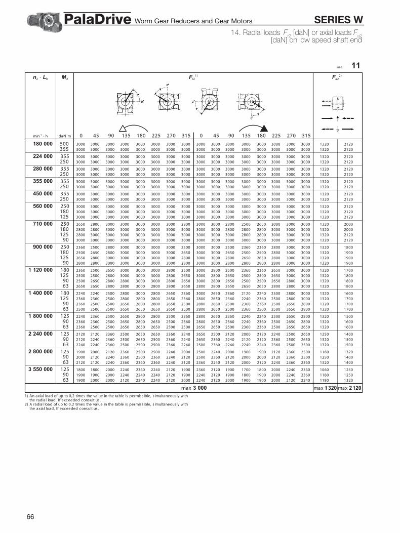
66
s ize 11
1) An axial load of up to 0,2 times the value in the table is permiss ible, s imultaneously withthe radial load. If exc eeded c onsult us .
2) A radial load of up to 0,2 times the value in the table is permiss ible, s imultaneously withthe axial load. If exc eeded c onsult us .
n2 · Lh M2 Fr21) Fa2
2)
min-1 · h daN m 0 45 90 135 180 225 270 315 0 45 90 135 180 225 270 315
180 000 500 3000 3000 3000 3000 3000 3000 3000 3000 3000 3000 3000 3000 3000 3000 3000 3000 1320 2120355 3000 3000 3000 3000 3000 3000 3000 3000 3000 3000 3000 3000 3000 3000 3000 3000 1320 2120
224 000 355 3000 3000 3000 3000 3000 3000 3000 3000 3000 3000 3000 3000 3000 3000 3000 3000 1320 2120250 3000 3000 3000 3000 3000 3000 3000 3000 3000 3000 3000 3000 3000 3000 3000 3000 1320 2120
280 000 355 3000 3000 3000 3000 3000 3000 3000 3000 3000 3000 3000 3000 3000 3000 3000 3000 1320 2120250 3000 3000 3000 3000 3000 3000 3000 3000 3000 3000 3000 3000 3000 3000 3000 3000 1320 2120
355 000 355 3000 3000 3000 3000 3000 3000 3000 3000 3000 3000 3000 3000 3000 3000 3000 3000 1320 2120250 3000 3000 3000 3000 3000 3000 3000 3000 3000 3000 3000 3000 3000 3000 3000 3000 1320 2120
450 000 355 3000 3000 3000 3000 3000 3000 3000 3000 3000 3000 3000 3000 3000 3000 3000 3000 1320 2120250 3000 3000 3000 3000 3000 3000 3000 3000 3000 3000 3000 3000 3000 3000 3000 3000 1320 2120
560 000 250 3000 3000 3000 3000 3000 3000 3000 3000 3000 3000 3000 3000 3000 3000 3000 3000 1320 2120180 3000 3000 3000 3000 3000 3000 3000 3000 3000 3000 3000 3000 3000 3000 3000 3000 1320 2120125 3000 3000 3000 3000 3000 3000 3000 3000 3000 3000 3000 3000 3000 3000 3000 3000 1320 2120
710 000 250 2650 2800 3000 3000 3000 3000 3000 2800 3000 3000 2800 2500 2650 3000 3000 3000 1320 2000180 2800 2800 3000 3000 3000 3000 3000 3000 3000 3000 2800 2800 2800 3000 3000 3000 1320 2000125 2800 3000 3000 3000 3000 3000 3000 3000 3000 3000 3000 2800 2800 3000 3000 3000 1320 2120
90 3000 3000 3000 3000 3000 3000 3000 3000 3000 3000 3000 3000 3000 3000 3000 3000 1320 2120
900 000 250 2360 2500 2800 3000 3000 3000 3000 2500 3000 3000 2500 2360 2360 2800 3000 3000 1320 1800180 2500 2650 2800 3000 3000 3000 3000 2650 3000 3000 2650 2500 2500 2800 3000 3000 1320 1900125 2650 2800 3000 3000 3000 3000 3000 2800 3000 3000 2800 2650 2650 2800 3000 3000 1320 1900
90 2800 2800 3000 3000 3000 3000 3000 2800 3000 3000 2800 2800 2800 2800 3000 3000 1320 1900
1 120 000 180 2360 2500 2650 3000 3000 3000 2800 2500 3000 2800 2500 2360 2360 2650 3000 3000 1320 1700125 2500 2500 2800 3000 3000 3000 2800 2650 3000 2800 2650 2500 2500 2650 3000 3000 1320 1800
90 2500 2650 2800 2800 3000 3000 2800 2650 3000 2800 2650 2500 2500 2650 2800 3000 1320 180063 2650 2650 2800 2800 3000 2800 2800 2650 2800 2800 2650 2650 2650 2800 2800 3000 1320 1800
1 400 000 180 2240 2240 2500 2800 3000 2800 2650 2360 3000 2650 2360 2120 2240 2500 2800 3000 1320 1600125 2360 2360 2500 2800 2800 2800 2650 2360 2800 2650 2360 2240 2360 2500 2800 3000 1320 1700
90 2360 2500 2500 2650 2800 2800 2650 2500 2800 2650 2500 2360 2360 2500 2650 2800 1320 170063 2500 2500 2500 2650 2650 2650 2650 2500 2800 2650 2500 2360 2500 2500 2650 2800 1320 1700
1 800 000 125 2240 2360 2500 2650 2800 2800 2500 2360 2800 2650 2360 2240 2240 2500 2650 2800 1320 150090 2360 2360 2500 2650 2800 2650 2500 2360 2800 2650 2360 2240 2360 2500 2650 2800 1320 160063 2360 2500 2500 2650 2650 2650 2500 2500 2650 2650 2500 2360 2360 2500 2650 2650 1320 1600
2 240 000 125 2120 2120 2360 2500 2650 2650 2360 2240 2650 2500 2120 2000 2120 2240 2500 2650 1250 140090 2120 2240 2360 2500 2650 2500 2360 2240 2650 2360 2240 2120 2120 2360 2500 2650 1320 150063 2240 2240 2360 2500 2500 2500 2360 2240 2500 2360 2240 2240 2240 2360 2500 2500 1320 1500
2 800 000 125 1900 2000 2120 2360 2500 2500 2240 2000 2500 2240 2000 1900 1900 2120 2360 2500 1180 132090 2000 2120 2240 2360 2500 2360 2240 2120 2500 2360 2120 2000 2000 2120 2360 2500 1250 140063 2120 2120 2240 2360 2360 2360 2240 2120 2360 2240 2120 2000 2120 2240 2360 2360 1320 1400
3 550 000 125 1800 1800 2000 2240 2360 2240 2120 1900 2360 2120 1900 1700 1800 2000 2240 2360 1060 125090 1900 1900 2000 2240 2240 2240 2120 1900 2240 2120 1900 1800 1900 2000 2240 2360 1180 125063 1900 2000 2000 2120 2240 2240 2120 2000 2240 2120 2000 1900 1900 2000 2120 2240 1180 1320
max 1320 max 2120max 3 000
14. Radial loads Fr2 [daN] or axial loads F
a2[daN] on low speed shaft end
Worm Gear Reducers and Gear Motors SERIES WPalaDrive

67
s ize 12
1) An axial load of up to 0,2 times the value in the table is permiss ible, s imultaneously withthe radial load. If exc eeded c onsult us .
2) A radial load of up to 0,2 times the value in the table is permiss ible, s imultaneously withthe axial load. If exc eeded c onsult us .
n2 · Lh M2 Fr21) Fa2
2)
min-1 · h daN m 0 45 90 135 180 225 270 315 0 45 90 135 180 225 270 315
180 000 500 3000 3000 3000 3000 3000 3000 3000 3000 3000 3000 3000 3000 3000 3000 3000 3000 1320 2120355 3000 3000 3000 3000 3000 3000 3000 3000 3000 3000 3000 3000 3000 3000 3000 3000 1320 2120
224 000 355 3000 3000 3000 3000 3000 3000 3000 3000 3000 3000 3000 3000 3000 3000 3000 3000 1320 2120250 3000 3000 3000 3000 3000 3000 3000 3000 3000 3000 3000 3000 3000 3000 3000 3000 1320 2120
280 000 355 3000 3000 3000 3000 3000 3000 3000 3000 3000 3000 3000 3000 3000 3000 3000 3000 1320 2120250 3000 3000 3000 3000 3000 3000 3000 3000 3000 3000 3000 3000 3000 3000 3000 3000 1320 2120
355 000 355 3000 3000 3000 3000 3000 3000 3000 3000 3000 3000 3000 3000 3000 3000 3000 3000 1320 2120250 3000 3000 3000 3000 3000 3000 3000 3000 3000 3000 3000 3000 3000 3000 3000 3000 1320 2120
450 000 355 3000 3000 3000 3000 3000 3000 3000 3000 3000 3000 3000 3000 3000 3000 3000 3000 1320 2120250 3000 3000 3000 3000 3000 3000 3000 3000 3000 3000 3000 3000 3000 3000 3000 3000 1320 2120
560 000 250 3000 3000 3000 3000 3000 3000 3000 3000 3000 3000 3000 3000 3000 3000 3000 3000 1320 2120180 3000 3000 3000 3000 3000 3000 3000 3000 3000 3000 3000 3000 3000 3000 3000 3000 1320 2120125 3000 3000 3000 3000 3000 3000 3000 3000 3000 3000 3000 3000 3000 3000 3000 3000 1320 2120
710 000 250 2650 2800 3000 3000 3000 3000 3000 2800 3000 3000 2800 2500 2650 3000 3000 3000 1320 2000180 2800 2800 3000 3000 3000 3000 3000 3000 3000 3000 2800 2800 2800 3000 3000 3000 1320 2000125 2800 3000 3000 3000 3000 3000 3000 3000 3000 3000 3000 2800 2800 3000 3000 3000 1320 2120
90 3000 3000 3000 3000 3000 3000 3000 3000 3000 3000 3000 3000 3000 3000 3000 3000 1320 2120
900 000 250 2360 2500 2800 3000 3000 3000 3000 2500 3000 3000 2500 2360 2360 2800 3000 3000 1320 1800180 2500 2650 2800 3000 3000 3000 3000 2650 3000 3000 2650 2500 2500 2800 3000 3000 1320 1900125 2650 2800 3000 3000 3000 3000 3000 2800 3000 3000 2800 2650 2650 2800 3000 3000 1320 1900
90 2800 2800 3000 3000 3000 3000 3000 2800 3000 3000 2800 2800 2800 2800 3000 3000 1320 1900
1 120 000 180 2360 2500 2650 3000 3000 3000 2800 2500 3000 2800 2500 2360 2360 2650 3000 3000 1320 1700125 2500 2500 2800 3000 3000 3000 2800 2650 3000 2800 2650 2500 2500 2650 3000 3000 1320 1800
90 2500 2650 2800 2800 3000 3000 2800 2650 3000 2800 2650 2500 2500 2650 2800 3000 1320 180063 2650 2650 2800 2800 3000 2800 2800 2650 2800 2800 2650 2650 2650 2800 2800 3000 1320 1800
1 400 000 180 2240 2240 2500 2800 3000 2800 2650 2360 3000 2650 2360 2120 2240 2500 2800 3000 1320 1600125 2360 2360 2500 2800 2800 2800 2650 2360 2800 2650 2360 2240 2360 2500 2800 3000 1320 1700
90 2360 2500 2500 2650 2800 2800 2650 2500 2800 2650 2500 2360 2360 2500 2650 2800 1320 170063 2500 2500 2500 2650 2650 2650 2650 2500 2800 2650 2500 2360 2500 2500 2650 2800 1320 1700
1 800 000 125 2240 2360 2500 2650 2800 2800 2500 2360 2800 2650 2360 2240 2240 2500 2650 2800 1320 150090 2360 2360 2500 2650 2800 2650 2500 2360 2800 2650 2360 2240 2360 2500 2650 2800 1320 160063 2360 2500 2500 2650 2650 2650 2500 2500 2650 2650 2500 2360 2360 2500 2650 2650 1320 1600
2 240 000 125 2120 2120 2360 2500 2650 2650 2360 2240 2650 2500 2120 2000 2120 2240 2500 2650 1250 140090 2120 2240 2360 2500 2650 2500 2360 2240 2650 2360 2240 2120 2120 2360 2500 2650 1320 150063 2240 2240 2360 2500 2500 2500 2360 2240 2500 2360 2240 2240 2240 2360 2500 2500 1320 1500
2 800 000 125 1900 2000 2120 2360 2500 2500 2240 2000 2500 2240 2000 1900 1900 2120 2360 2500 1180 132090 2000 2120 2240 2360 2500 2360 2240 2120 2500 2360 2120 2000 2000 2120 2360 2500 1250 140063 2120 2120 2240 2360 2360 2360 2240 2120 2360 2240 2120 2000 2120 2240 2360 2360 1320 1400
3 550 000 125 1800 1800 2000 2240 2360 2240 2120 1900 2360 2120 1900 1700 1800 2000 2240 2360 1060 125090 1900 1900 2000 2240 2240 2240 2120 1900 2240 2120 1900 1800 1900 2000 2240 2360 1180 125063 1900 2000 2000 2120 2240 2240 2120 2000 2240 2120 2000 1900 1900 2000 2120 2240 1180 1320
max 1320 max 2120max 3 000
14. Radial loads Fr2 [daN] or axial loads F
a2[daN] on low speed shaft end
Worm Gear Reducers and Gear Motors SERIES WPalaDrive

68
s ize 13
1) An axial load of up to 0,2 times the value in the table is permiss ible, s imultaneously withthe radial load. If exc eeded c onsult us .
2) A radial load of up to 0,2 times the value in the table is permiss ible, s imultaneously withthe axial load. If exc eeded c onsult us .
n2 · Lh M2 Fr21) Fa2
2)
min-1 · h daN m 0 45 90 135 180 225 270 315 0 45 90 135 180 225 270 315
140 000 1000 4500 4500 4500 4500 4500 4500 4500 4500 4500 4500 4500 4500 4500 4500 4500 4500 2000 3150710 4500 4500 4500 4500 4500 4500 4500 4500 4500 4500 4500 4500 4500 4500 4500 4500 2000 3150
180 000 1000 4500 4500 4500 4500 4500 4500 4500 4500 4500 4500 4500 4500 4500 4500 4500 4500 2000 3150710 4500 4500 4500 4500 4500 4500 4500 4500 4500 4500 4500 4500 4500 4500 4500 4500 2000 3150500 4500 4500 4500 4500 4500 4500 4500 4500 4500 4500 4500 4500 4500 4500 4500 4500 2000 3150
224 000 710 4500 4500 4500 4500 4500 4500 4500 4500 4500 4500 4500 4500 4500 4500 4500 4500 2000 3150500 4500 4500 4500 4500 4500 4500 4500 4500 4500 4500 4500 4500 4500 4500 4500 4500 2000 3150355 4500 4500 4500 4500 4500 4500 4500 4500 4500 4500 4500 4500 4500 4500 4500 4500 2000 3150
280 000 710 4500 4500 4500 4500 4500 4500 4500 4500 4500 4500 4500 4250 4500 4500 4500 4500 2000 3150500 4500 4500 4500 4500 4500 4500 4500 4500 4500 4500 4500 4500 4500 4500 4500 4500 2000 3150355 4500 4500 4500 4500 4500 4500 4500 4500 4500 4500 4500 4500 4500 4500 4500 4500 2000 3150250 4500 4500 4500 4500 4500 4500 4500 4500 4500 4500 4500 4500 4500 4500 4500 4500 2000 3150180 4500 4500 4500 4500 4500 4500 4500 4500 4500 4500 4500 4500 4500 4500 4500 4500 2000 3150
355 000 500 4500 4500 4500 4500 4500 4500 4500 4500 4500 4500 4500 4250 4500 4500 4500 4500 2000 3150355 4500 4500 4500 4500 4500 4500 4500 4500 4500 4500 4500 4500 4500 4500 4500 4500 2000 3150250 4500 4500 4500 4500 4500 4500 4500 4500 4500 4500 4500 4500 4500 4500 4500 4500 2000 3150180 4500 4500 4500 4500 4500 4500 4500 4500 4500 4500 4500 4500 4500 4500 4500 4500 2000 3150
450 000 500 4000 4250 4500 4500 4500 4500 4500 4500 4500 4500 4250 4000 4000 4500 4500 4500 2000 3150355 4250 4500 4500 4500 4500 4500 4500 4500 4500 4500 4500 4250 4250 4500 4500 4500 2000 3150250 4500 4500 4500 4500 4500 4500 4500 4500 4500 4500 4500 4500 4500 4500 4500 4500 2000 3150180 4500 4500 4500 4500 4500 4500 4500 4500 4500 4500 4500 4500 4500 4500 4500 4500 2000 3150
560 000 500 3750 4000 4500 4500 4500 4500 4500 4000 4500 4500 4000 3550 3750 4250 4500 4500 2000 3000355 4000 4250 4500 4500 4500 4500 4500 4250 4500 4500 4250 4000 4000 4500 4500 4500 2000 3000250 4250 4250 4500 4500 4500 4500 4500 4250 4500 4500 4250 4000 4250 4500 4500 4500 2000 3150180 4250 4250 4500 4500 4500 4500 4500 4500 4500 4500 4250 4250 4250 4500 4500 4500 2000 3150125 4500 4500 4500 4500 4500 4500 4500 4500 4500 4500 4500 4250 4500 4500 4500 4500 2000 3150
710 000 500 3350 3550 4250 4500 4500 4500 4250 3750 4500 4250 3550 3350 3350 4000 4500 4500 2000 2650355 4000 3750 4250 4500 4500 4500 4250 3750 4500 4250 3750 3550 3750 4000 4500 4500 2000 2800250 4000 4000 4250 4500 4500 4500 4250 4000 4500 4250 4000 3750 3750 4250 4500 4500 2000 3000180 4000 4000 4250 4500 4500 4500 4250 4000 4500 4250 4000 4000 4000 4250 4500 4500 2000 3000125 4000 4250 4250 4500 4500 4500 4250 4250 4500 4250 4250 4000 4000 4250 4500 4500 2000 3000
900 000 355 3350 3550 4000 4250 4500 4500 4000 3550 4500 4000 3550 3350 3350 3750 4250 4500 2000 2650250 3550 3750 4000 4250 4500 4250 4000 3750 4500 4000 3750 3550 3550 4000 4250 4500 2000 2650180 3750 3750 4000 4250 4250 4250 4000 3750 4250 4000 3750 3550 3750 4000 4250 4250 2000 2800125 3750 3750 4000 4250 4250 4250 4000 3750 4250 4000 3750 3750 3750 4000 4250 4250 2000 2800
1 120 000 355 3150 3350 3750 4000 4250 4250 3750 3350 4250 3750 3350 3000 3150 3550 4000 4500 2000 2500250 3350 3350 3750 4000 4250 4000 3750 3350 4250 3750 3350 3150 3350 3550 4000 4250 2000 2500180 3350 3550 3750 4000 4000 4000 3750 3550 4000 3750 3550 3350 3350 3550 4000 4000 2000 2500125 3550 3550 3750 4000 4000 4000 3750 3550 4000 3750 3550 3550 3550 3750 4000 4000 2000 2650
1 400 000 355 3000 3000 3350 4000 4000 4000 3550 3000 4000 3550 3000 2800 2800 3350 3750 4250 1900 2240250 3000 3150 3550 3750 4000 3750 3550 3150 4000 3550 3150 3000 3000 3350 3750 4000 2000 2360180 3150 3350 3550 3750 3750 3750 3550 3350 3750 3550 3350 3150 3150 3350 3750 3750 2000 2360125 3350 3350 3550 3550 3750 3550 3550 3350 3750 3550 3350 3150 3350 3350 3550 3750 2000 2360
1 800 000 355 2650 2800 3150 3550 3750 3550 3150 2800 3750 3350 2800 2500 2650 3000 3550 4000 1700 2120250 2800 3000 3150 3550 3550 3550 3150 3000 3550 3350 3000 2800 2800 3150 3550 3750 1900 2120180 3000 3000 3150 3350 3550 3350 3150 3000 3550 3350 3000 2800 3000 3150 3350 3550 2000 2240125 3000 3000 3150 3350 3350 3350 3150 3150 3350 3350 3000 3000 3000 3150 3350 3550 2000 2240
2 240 000 250 2650 2650 3000 3350 3350 3350 3000 2800 3350 3000 2650 2500 2650 3000 3350 3550 1800 2000180 2800 2800 3000 3150 3350 3150 3000 2800 3350 3000 2800 2650 2650 3000 3150 3350 1900 2000125 2800 2800 3000 3150 3150 3150 3000 2800 3150 3000 2800 2800 2800 3000 3150 3350 2000 2120
2 800 000 250 2360 2500 2800 3150 3350 3150 2800 2500 3150 2800 2500 2360 2360 2650 3150 3350 1600 1900180 2500 2650 2800 3000 3150 3000 2800 2650 3150 2800 2650 2500 2500 2800 3000 3150 1700 1900125 2650 2650 2800 3000 3000 3000 2800 2650 3000 2800 2650 2650 2650 2800 3000 3000 1800 1900
3 550 000 250 2240 2360 2650 3000 3000 3000 2650 2360 3000 2650 2360 2120 2240 2360 3000 3150 1500 1700180 2360 2360 2650 2800 3000 2800 2650 2360 3000 2650 2360 2240 2360 2500 2800 3000 1600 1800125 2360 2500 2650 2800 2800 2800 2650 2500 2800 2650 2500 2360 2360 2650 2800 3000 1700 1800
max 2 000 max 3150max 4 500
14. Radial loads Fr2 [daN] or axial loads Fa2[daN] on low speed shaft end
Worm Gear Reducers and Gear Motors SERIES WPalaDrive

69
s ize 14
1) An axial load of up to 0,2 times the value in the table is permiss ible, s imultaneously withthe radial load. If exc eeded c onsult us .
2) A radial load of up to 0,2 times the value in the table is permiss ible, s imultaneously withthe axial load. If exc eeded c onsult us .
n2 · Lh M2 Fr21) Fa2
2)
min-1 · h daN m 0 45 90 135 180 225 270 315 0 45 90 135 180 225 270 315
size 14 bisValues valid for solid low speed shaft (see ch. 17).
180 000 1900 5000 5600 6300 6300 6300 6300 6300 6000 6300 6300 5600 4500 4750 6300 6300 6300 1400 30001320 6000 6300 6300 6300 6300 6300 6300 6300 6300 6300 6300 5600 6000 6300 6300 6300 2000 3000
224 000 1320 5300 6000 6300 6300 6300 6300 6300 6000 6300 6300 6000 5000 5300 6300 6300 6300 1800 2800950 6000 6300 6300 6300 6300 6300 6300 6300 6300 6300 6300 6000 6000 6300 6300 6300 2240 3000
280 000 1320 5000 5300 6300 6300 6300 6300 6300 5600 6300 6300 5300 4500 4750 6000 6300 6300 1600 2650950 5600 6000 6300 6300 6300 6300 6300 6000 6300 6300 6000 5300 5600 6300 6300 6300 2000 2800670 6000 6300 6300 6300 6300 6300 6300 6300 6300 6300 6300 6000 6000 6300 6300 6300 2320 2800
355 000 950 5000 5300 6300 6300 6300 6300 6300 5600 6300 6300 5300 4750 5000 6000 6300 6300 1800 2500670 5600 5600 6300 6300 6300 6300 6300 6000 6300 6300 6000 5300 6000 6300 6300 6300 2120 2650475 6000 6000 6300 6300 6300 6300 6300 6000 6300 6300 6000 5600 6000 6300 6300 6300 2360 2650
450 000 950 4500 4750 5600 6300 6300 6300 6300 5000 6300 6300 5000 4250 4500 5600 6300 6300 1600 2360670 5000 5300 6000 6300 6300 6300 6300 5300 6300 6300 5300 4750 5000 6000 6300 6300 1900 2500475 5300 5600 6000 6300 6300 6300 6000 5600 6300 6300 5600 5300 5300 6000 6300 6300 2120 2500
560 000 950 4250 4500 5300 6300 6300 6300 5600 4750 6300 6000 4500 4000 4250 5000 6300 6300 1500 2240670 4750 4750 5600 6300 6300 6300 5600 5000 6300 6000 5000 4500 4500 5300 6300 6300 1700 2240475 5000 5000 5600 6000 6300 6300 5600 5300 6300 6000 5300 4750 5000 5600 6000 6300 1900 2360335 5300 5300 5600 6000 6300 6000 5600 5300 6300 6000 5300 5000 5300 5600 6000 6300 2120 2360
710 000 950 3750 4000 5000 6000 6300 6300 5300 4250 6300 5300 4250 3550 3750 4750 6000 6300 1250 2000670 4250 4500 5000 6000 6300 6000 5300 4500 6300 5600 4500 4000 4250 5000 6000 6300 1600 2120475 4500 4750 5300 6000 6000 6000 5300 4750 6000 5300 4750 4500 4500 5000 5600 6300 1800 2120335 4750 5000 5300 5600 6000 6000 5300 5000 6000 5300 5000 4750 4750 5300 5600 6000 1900 2240
900 000 670 4000 4000 4750 5600 6000 6000 5000 4250 6000 5000 4250 3750 3750 4500 5600 6300 1400 1900475 4250 4250 4750 5300 5600 5600 5000 4500 5600 5000 4500 4000 4250 4750 5300 6000 1600 2000335 4500 4500 4750 5300 5600 5300 5000 4500 5600 5000 4500 4250 4500 4750 5300 5600 1800 2000
1 120 000 670 3550 3750 4500 5300 5600 5300 4750 4000 5600 4750 3750 3350 3550 4250 5300 6000 1250 1800475 4000 4000 4500 5000 5300 5300 4750 4250 5300 4750 4000 3750 4000 4250 5000 5600 1500 1900335 4000 4250 4500 5000 5300 5000 4750 4250 5300 4750 4250 4000 4000 4500 5000 5300 1600 1900
1 400 000 670 3350 3550 4000 5000 5300 5000 4250 3550 5300 4500 3550 3150 3150 4000 4750 5600 1180 1700475 3550 3750 4250 4750 5000 5000 4250 3750 5000 4500 3750 3550 3550 4000 4750 5300 1400 1700335 3750 4000 4250 4750 4750 4750 4250 4000 4750 4500 4000 3750 3750 4250 4750 5000 1500 1800
1 800 000 670 3000 3150 3750 4500 5000 4750 4000 3350 5000 4000 3150 2800 3000 3550 4500 5300 1000 1500475 3350 3350 4000 4500 4750 4500 4000 3550 4750 4250 3550 3150 3350 3750 4500 5000 1250 1600335 3550 3550 4000 4250 4500 4500 4000 3750 4500 4250 3750 3350 3550 3750 4250 4750 1400 1600
2 240 000 475 3000 3150 3550 4250 4500 4250 3750 3350 4500 4000 3150 3000 3000 3550 4250 4750 1120 1500335 3150 3350 3750 4000 4250 4250 3750 3350 4250 3750 3350 3150 3150 3550 4000 4500 1250 1500
180 000 1900 7100 7100 7100 7100 7100 7100 7100 7100 7100 7100 7100 7100 7100 7100 7100 7100 3150 5000
224 000 1320 7100 7100 7100 7100 7100 7100 7100 7100 7100 7100 7100 7100 7100 7100 7100 7100 3150 5000
280 000 1320 7100 7100 7100 7100 7100 7100 7100 7100 7100 7100 7100 7100 7100 7100 7100 7100 3150 5000
355 000 950 7100 7100 7100 7100 7100 7100 7100 7100 7100 7100 7100 7100 7100 7100 7100 7100 3150 5000
450 000 950 7100 7100 7100 7100 7100 7100 7100 7100 7100 7100 7100 7100 7100 7100 7100 7100 3150 5000
560 000 950 7100 7100 7100 7100 7100 7100 7100 7100 7100 7100 7100 6700 7100 7100 7100 7100 3150 4500
710 000 950 6700 7100 7100 7100 7100 7100 7100 7100 7100 7100 7100 6300 6700 7100 7100 7100 3150 4250670 7100 7100 7100 7100 7100 7100 7100 7100 7100 7100 7100 7100 7100 7100 7100 7100 3150 4500
900 000 950 6700 6700 7100 7100 7100 7100 7100 6700 7100 7100 6700 6300 6700 7100 7100 7100 3150 4000670 6700 7100 7100 7100 7100 7100 7100 7100 7100 7100 7100 6700 6700 7100 7100 7100 3150 4250
1 120 000 670 6000 6300 7100 7100 7100 7100 7100 6300 7100 7100 6300 6000 6000 6700 7100 7100 3000 3750475 6300 6700 7100 7100 7100 7100 7100 6700 7100 7100 6700 6300 6300 6700 7100 7100 3150 4000335 6700 6700 7100 7100 7100 7100 7100 6700 7100 7100 6700 6700 6700 7100 7100 7100 3150 4000
1 400 000 670 5600 6000 6300 7100 7100 7100 6700 6000 7100 6700 6000 5300 5600 6300 7100 7100 2800 3550475 6000 6000 6700 7100 7100 7100 6700 6000 7100 6700 6000 6000 6000 6300 7100 7100 3150 3550335 6000 6300 6700 7100 7100 7100 6700 6300 7100 6700 6300 6000 6000 6300 7100 7100 3150 3750
1 800 000 670 5000 5300 6000 6700 7100 6700 6000 5300 7100 6300 5300 5000 5000 6000 6700 7100 2650 3150475 5300 5600 6000 6700 6700 6700 6000 5600 6700 6300 5600 5300 5300 6000 6700 7100 3000 3350335 5600 5600 6000 6300 6700 6700 6000 6000 6700 6300 6000 5600 5600 6000 6300 6700 3150 3350
2 240 000 475 5000 5300 5600 6300 6300 6300 5600 5300 6300 6000 5300 5000 5000 5600 6000 6700 2650 3150335 5300 5300 5600 6000 6300 6000 5600 5300 6300 6000 5300 5300 5300 5600 6000 6300 3000 3150
max 2 800 max 4 500max 6 300
max 3 150 max 5 000max 7 100
14. Radial loads Fr2 [daN] or axial loads F
a2[daN] on low speed shaft end
Worm Gear Reducers and Gear Motors SERIES WPalaDrive

70
Worm gear pairNumber of teeth – wormwheel z2 and worm z1, axial module mx, ref-erenc e lead angle y m, s tatic effic ienc y and worm gear pairmoment of intertia J 1 for gear reduc ers and gearmotors W 1, W 2 ,MW 1, MW 2 , MW 3 .
In the c ase of W 2 , MW 2 and MW 3 gear reduc ers and gearmotors , the moment ofinertia on the high speed shaft (dis regarding motor) is that of the worm divided by thec ylindric al gear pair total ratio squared.
Low speed shaft angular backlashA rough guide for low speed shaft angularbac klash is given in the table (the wormbeing held stationary). Values vari ac c ordingto des ign and temperature.G ear reduc ers with controlled or reducedbacklash can be supplied on request (seec h. 17), subjec t to longer delivery times andpric e addition; c hoose a higher servic e fac-tor.
1) At a distanc e of 1 m from the low speed shaft centre,angular bac klash in mm is obtained multiplying the tablevalue by 1 000 (1 rad = 3438’).
Angular bac klash [rad]1)G ear reduc ers ize
min max01 0,0030 0,011802 0,0025 0,010003 0,0020 0,0080
04, 05 0,0018 0,007106, 07 0,0016 0,0063
08 0,0013 0,0050
09, 10 0,0011 0,0045 11, 12 0,0010 0,0040 13 0,0008 0,0032
14 0,0007 0,0028
G ear reduc er s ize
i 01 02 03 04, 05 06, 07 08 09, 10 11, 12 13 14
7 z2/z1 21/3 21/3 21/3 28/4 28/4mx 2,2 2,8 3,4 3,5 4,5
m 22° 28’ 22° 29’ 22° 35’ 28° 35’ 28° 30’ – – – – –s 0,71 0,71 0,71 0,74 0,74
10 z2/z1 20/2 20/2 20/2 30/3 30/3 30/3 30/3 30/3mx 2,3 2,8 3,5 3,3 4,2 5,3 6,6 8,6
m 15° 10’ 15° 10’ 15° 7’ 19° 52’ 20° 28’ 21° 20’ 21° 53’ 23° 1’ – –s 0,65 0,65 0,65 0,69 0,7 0,7 0,7 0,72
13 z2/z1 26/2 26/2 26/2 26/2 26/2 26/2 39/3 39/3 39/3mx 1,8 2,3 2,9 3,7 4,7 5,9 5,2 6,8 8,5
m 13° 28’ 13° 14’ 13° 36’ 14° 23’ 14° 48’ 15° 24’ 18° 48’ 19° 52’ 20° 38’ –s 0,62 0,62 0,63 0,64 0,64 0,65 0,68 0,69 0,7
16 z2/z1 32/2 32/2 32/2 32/2 32/2 32/2 32/2 32/2 48/3 48/3mx 1,5 1,9 2,4 3,1 3,9 4,9 6,2 8 7,1 9
m 11° 52’ 11° 53’ 12° 4’ 12° 47’ 13° 14’ 13° 47’ 14° 7’ 14° 52’ 19° 4’ 20° 21’s 0,6 0,6 0,6 0,61 0,62 0,63 0,63 0,64 0,68 0,69
20 z2/z1 20/1 20/1 20/1 40/2 40/2 40/2 40/2 40/2 40/2 40/2mx 2,3 2,8 3,5 2,5 3,2 4,1 5,1 6,6 8,3 10,4
m 7° 41’ 7° 40’ 7° 46’ 11° 46’ 12° 1’ 12° 29’ 12° 24’ 13° 6’ 13° 36’ 14° 3’s 0,5 0,5 0,5 0,6 0,6 0,61 0,61 0,62 0,63 0,63
25 z2/z1 25/1 25/1 25/1 25/1 25/1 25/1 50/2 50/2 50/2 50/2mx 1,9 2,4 3 3,8 4,8 6,1 4,2 5,4 6,8 8,6
m 6° 55’ 6° 52’ 6° 58’ 7° 21’ 7° 34’ 7° 53’ 11° 33’ 11° 49’ 12° 28’ 13° 18’s 0,48 0,48 0,48 0,5 0,5 0,51 0,59 0,6 0,61 0,62
32 z2/z1 32/1 32/1 32/1 32/1 32/1 32/1 32/1 32/1 32/1 64/2mx 1,5 1,9 2,4 3,1 3,9 4,9 6,2 8 10,1 6,8
m 6° 6° 6° 3’ 6° 25’ 6° 38’ 6° 55’ 7° 5’ 7° 27’ 7° 43’ 11° 22’s 0,45 0,45 0,45 0,46 0,47 0,48 0,49 0,5 0,51 0,59
40 z2/z1 40/1 40/1 40/1 40/1 40/1 40/1 40/1 40/1 40/1 40/1mx 1,3 1,6 2 2,5 3,2 4,1 5,1 6,6 8,3 10,4
m 5° 12’ 5° 10’ 5° 16’ 5° 54’ 6° 2’ 6° 16’ 6° 13’ 6° 34’ 6° 50’ 7° 3’s 0,42 0,42 0,42 0,44 0,45 0,46 0,46 0,47 0,48 0,49
50 z2/z1 50/1 50/1 50/1 50/1 50/1 50/1 50/1 50/1 50/1 50/1mx 1 1,3 1,6 2,1 2,7 3,3 4,2 5,4 6,8 8,6
m 4° 29’ 4° 25’ 4° 32’ 5° 7’ 5° 15’ 5° 27’ 5° 48’ 5° 56’ 6° 15’ 6° 41’s 0,38 0,38 0,38 0,41 0,42 0,43 0,44 0,45 0,46 0,47
63 z2/z1 63/1 63/1 63/1 63/1 63/1 63/1 63/1 63/1 63/1mx 1 1,3 1,7 2,1 2,7 3,4 4,4 5,5 6,9
m – 3° 43’ 3° 50’ 4° 21’ 4° 27’ 4° 39’ 4° 57’ 5° 5’ 5° 22’ 5° 46’s 0,34 0,35 0,38 0,38 0,39 0,4 0,41 0,42 0,44
Momento di inerzia (di massa)J 1 [kg m2] sulla vite ≈
– – – – – 0,0014 0,0037 0,0078 0,0192 0,0376Moment of inertia (of mass)J 1 [kg m2] on the worm ≈
s
15. Structural and operational details
15. Structural and operational details
Worm Gear Reducers and Gear Motors SERIES WPalaDrive

71
15. Structural and operational details
Efficiency Efficiency is derived from the PN2 / PN1 ratio in the case of gearreducers (ch. 7) and P2 / P1 in the case of gearmotors (ch. 9). Thevalues obtained will be valid assuming normal working conditions,worm operating as driving member, proper lubrication, adequaterunning-in (ch. 16), and a load near to the nominal value.During the initial working period (about 50 hours) and generally atevery cold start, efficiency will be lower (by about 12% for wormswith z1 = 1; 6% for worms with z1 = 2 and 3% for worms with z1 = 3).«Static» efficiency s on starting (see table in the preceding sec-tion) is much lower than («starting friction») must be overcome atspeed 0); as speed picks up gradually, efficiency will rise corre-spondingly until the catalogue value is reached.Inverse efficiency inv, – produced by the wormwheel as driver– is always less than . It can be calculated approximately as fol-lows:
≈ 2 – 1 / ; likewise: inv ≈ 2 – 1 /
IrreversibilityA worm gear reducer or gearmotor is dynamically irreversible (thatis, it ceases to turn the instant the wormshaft receives no further stimu-lus that would keep the worm itself in rotation e.g. motor torque, iner-tia from the worm and related fan, motor flywheels, couplings, etc.)when 0,5 as inv then drops below 0.This state becomes necessary wherever there is a need for stop-ping and holding the load, even without the aid of a brake. Wherecontinuous vibration occurs, dynamic irreversibility may not beobtainable.A gear reducer or gearmotor is statically irreversible (that is,rotation cannot be imparted by way of the low speed shaft) when
s
0,5.
This is a state necessary to keep the load at standstill; taking intoaccount, however, that efficiency can increase with time spent in oper-ation, it would be advisable to assume s 0,4 ( m 5°).Where continuous vibration occurs, static irreversibility may not beobtainable.A gear reducer or gearmotor has low static reversibility (i.e. rotationmay be imparted by way of the low speed shaft with high torqueand/or vibration) when 0,5
s 0,6 (7° 30’
m 12°).
A gear reducer or gearmotor has complete static reversibility (i.e.rotation may be imparted by way of the low speed shaft) when s 0,6 ( m 12°).This state is advisable where there is a need for easy start-up of thegear reducer by way of the low speed shaft.
OverloadsSince worm gear pairs are often subject to high static and dynamicoverloads by dint of the fact that they are especially suited to bearthem, the nedd arises – more so than with other gear pairs – for ver-ifying that such overloads will always remain lower than M2 max (ch. 7).Overloads are normally generated when one has:– starting on full load (especially for high inertias and low trans-
mission ratios), braking, shocks;– irreversible gear reducers, or gear reducers with low reversibility
in which the wormwheel becomes driver due to driven machineinertia;
– applied power higher than that required; other static or dynamiccauses.
The following general observations on overloads are accompaniedby some formulae for carrying out evaluations in certain typicalinstances.Where no evaluation is possible, install safety devices which willkeep values within 2 · MN2.
Starting torqueWhen starting on full load (especially for high inertias and low trans-mission ratios) verify that M2 max is equal to or greater than startingtorque, by using the following formula:
M2 start = · M2 available – M2 required + M2 required
where:M2 required is torque absorbed by the machine through work and friction;M2 available is output torque derived from the motor’s nominal power rating;J0 is the moment of inertia (of mass) of the motor;J is the external moment of inertia (of mass) in kg m2 (gear reducers, couplings, drivenmachine) referred to the motor shaft;for other symbols see ch. 2b.
NOTE: When seeking to verify that starting torque is sufficiently high for starting, take intoaccount efficiency s when evaluating M2 available, and starting friction, if any, in evaluat-ing M2 required.
JJ + J0·
M startMN
Stopping machines with high kinetic energy (high moments ofinertia combined with high speeds) with or without braking(braking applied to wormshaft, or use of brake motor)Select a gear reducer with static reversibility ( s 0,5); if using abrake motor, verify braking stress with the following formula:
( (· i + M2 required – M2 required M2 max
where:M f is the braking torque setting (see table in ch. 2b).
s inv is static inverse efficiency (see previous heading);for other symbols see above and ch.1.
Where selection of a statically reversible gear reducer is not pos-sible (i.e. s 0,5) slowing-down should be sufficiently gradual(avoiding application of excessive stress to the unit itself) as to ensurethat:
– M2 M2 max
where:J2 [kg m2] is the moment of inertia (of mass) of the driven machine referred to the gearreducer’s low speed shaft;M2 [daN m] is torque absorbed by the machine through work and friction;
2 [rad/s2] is the low speed shaft’s angular deceleration; this may be reduced by fly-wheel fitted to the wormshaft, electric deceleration ramps, lowering of braking torque whenbraking systems are in use, etc.
2 may be arrived at theorically (within broadly safe limits) or experimentally (by testingagainst stopping time and distance etc.).If a brake motor is in use, the following formula may be used for a safe evaluation of 2:
2 =
in which the motor is presumed without load and subject to its braking torque settingMf [daN m] (see table in ch. 2b).
Operation with brake motorStating time ta and revolutions of motor a1
ta = [s]; a1 = [rad]95,5 M start –
Braking time t f and revolutions of motor f1
t f = [s]; f1 = [rad]95,5 Mf+
where:
M start [daN m] is motor starting torque · (see ch. 2b);
M f [daN m] is the braking torque setting of the motor (see ch. 2b);for other symbols see above and ch. 1.
With the gear reducer run in and operating at normal running tem-perature – assuming a regular air-gap and ambient humidity and uti-lizing suitable electrical equipment – repetition of the braking action,as affected by variation in temperature of the brake and by the stateof wear of friction surface, is approx ± 0,1 · f1.During warm-up (1 3 h, small through to large sizes), brakingtimes and distances tend to increase to the point of stabilizing at oraround values corresponding to rated catalogue efficiency.
Duration of friction surfaceAs a rough guide, the number of applications permis-sible between successive adjustments of the air-gap isgiven by the following formula:
where:W [MJ] is the work of friction between successive adjustments of the air-gap as indicated in the table. For other symbols see above.
The air-gap should measure between 0,25 minimumand 0,7 maximum; as a rough guide, 5 adjustmentscan be made.
W · 105
M f · f1
M startMN
955 · P1
n1
M2 required· invi
t f · n1
19,1(J0 + J/ inv) · n1
M2 requiredi ·
ta · n1
19,1(J0 + J/ ) · n1
10 · MfJ0 · i
J2 · 2
10
JJ + J0 / s inv
M fs inv
WMotor sizeMJ
63 10,671 1480 1890 24
100 24112 45132 67
160, 180M 90180L, 200 125
( (
inv s s
:
Worm Gear Reducers and Gear Motors SERIES WPalaDrive
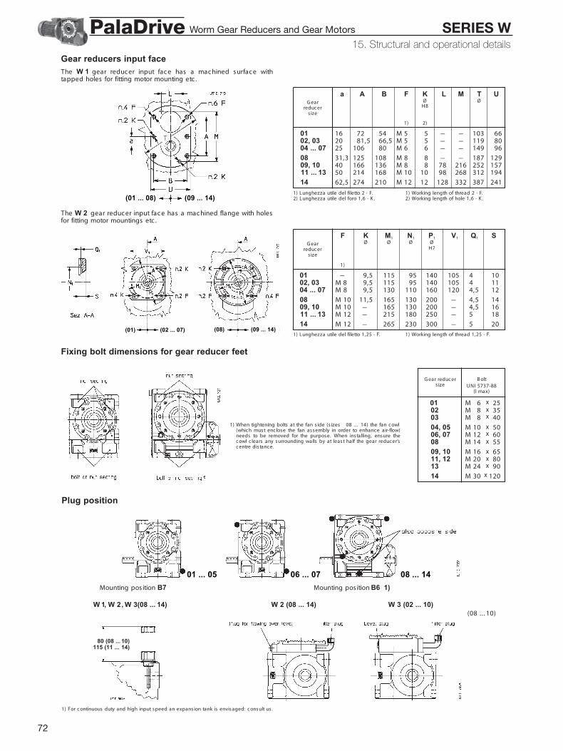
72
Gear reducers input faceThe W 1 gear reduc er input fac e has a mac hined surfac e withtapped holes for fitting motor mounting etc .
Fixing bolt dimensions for gear reducer feet
Plug position
The W 2 gear reduc er input fac e has a mac hined flange with holesfor fitting motor mountings etc .
a A B F K L M T UØ Ø
H8
1) 2)
01 16 72 54 M 5 5 – – 103 6602, 03 20 81,5 66,5 M 5 5 – – 119 8004 ... 07 25 106 80 M 6 6 – – 149 96
08 31,3 125 108 M 8 8 – – 187 129 09, 10 40 166 136 M 8 8 78 216 252 157 11 ... 13 50 214 168 M 10 10 98 268 312 194
14 62,5 274 210 M 12 12 128 332 387 241
G earreduc er
s ize
1) Lunghezza utile del filetto 2 · F.2) Lunghezza utile del foro 1,6 · K .
1) Working length of thread 2 · F.2) Working length of hole 1,6 · K .
F K M1 N1 P1 V1 Q1 SØ Ø Ø Ø
H7
1)
01 – 9,5 115 95 140 105 4 1002, 03 M 8 9,5 115 95 140 105 4 1104 ... 07 M 8 9,5 130 110 160 120 4,5 12
08 M 10 11,5 165 130 200 – 4,5 14 09, 10 M 10 – 165 130 200 – 4,5 16 11 ... 13 M 12 – 215 180 250 – 5 18
14 M 12 – 265 230 300 – 5 20
G earreduc er
s ize
1) Lunghezza utile del filetto 1,25 · F. 1) Working length of thread 1,25 · F.
1) When tightening bolts at the fan s ide (s izes 08 . . . 14) the fan c owl(whic h must enc lose the fan assembly in order to enhanc e air-flow)needs to be removed for the purpose. When installing, ensure thec owl c lears any s urrounding walls by at least half the gear reduc er’sc entre dis tanc e.
B oltG ear reduc erUNI 5737-88s ize
(l max)
01 M 6 2502 M 8 3503 M 8 40
04, 05 M 10 5006, 07 M 12 60
08 M 14 55
09, 10 M 16 65 11, 12 M 20 80 13 M 24 90
14 M 30 120
Mounting pos ition B7 Mounting pos ition B6 1)
W 1, W 2, W 3(08 ... 14) W 2 (08 ... 14) W 3 (02 ... 10)
1) For c ontinuous duty and high input speed an expans ion tank is envisaged: c onsult us .
(08 .. . 10)
(01 ... 08) (09 ... 14)
(01) (02 ... 07) (08) (09 ... 14)
01 ... 05 06 ... 07 08 ... 14
10)80 (08 ...115 (11 ... 14)
15. Structural and operational details
xxx
xxx
xxxx
Worm Gear Reducers and Gear Motors SERIES WPalaDrive

73
15. Structural and operational details
D D3 E E0 E1 E2 E3 l m m0 n rØ ØG ear reduc er
s izeH7/j6, k6 H7/h6
01 19 15 62,5 67 0 59 8 36 21 19,5 – 1,502 24 19 76,5 81 13 54 14 45 23,5 18,5 – 1,503 28 24 87 91,5 16,5 61 14 63 21,5 11,0 – 1,5
04, 05 32 27 110 – 57 34 10 70 28 – 6 1,506 38 32 134 – 71 39,5 12 90 30 – 6 1,507 40 34 134 – 71 39,5 12 90 30 – 6 1,5
08 48 41 162 – 87 46,5 14 110 35 – 7 2 09, 10 60 52 193 – 102 55 16 140 32 – 7 2 11 70 62 228 – 124 63 16 180 35 – 8 2
12 75 66 228 – 124 63 18 180 35 – 8 2 13 90 80 274 – 150 75 21 200 50 – 9 3 14 110 98 331 – 180 90 25 250 55 – 10 3
Worm Gear Reducers and Gear Motors SERIES WPalaDrive

74
GeneralB e s ure that the s truc ture on whic h gear reduc er or gearmotor isfitted is plane, levelled and s uffic iently dimens ioned in order toas s ure fitting s tability and vibration abs enc e, keeping in mind alltrans mitted forc es due to the mas s es , to the torque, to the radialand axial loads .
Pos ition the gear reduc er or gearmotor so as to allow a free passageof air for c ooling both gear reduc er and motor (espec ially at gearreduc er and motor fan s ides).
Avoid: any obstruc tion to the air-flow; heat sources near the gearreduc er that might affec t the temperature of c ooling-air and of gearreduc er for radiation; insuffic ient air rec yc le or any other fac tor hin-dering the steady diss ipation of heat.
Mount the gear reduc er so as not to rec eive vibrations .
When external loads are present use pins or loc king bloc ks , if ne-cessary.
When fitting gear reduc er and mac hine and/or gear reduc er andeventual flange B5 it is rec ommended to use locking adhesivessuch as LOC TITE on the fastening screws (also on flange matingsurfac es).
For outdoor ins tallation or in a hos tile environment protec t the gearreduc er or gearmotor with antic orros ion paint. Added protec tionmay be afforded by water-repellent greas e (es pec ially around therotary s eating of s eal rings and the ac c es s ible zones of s haftend).
G ear reduc ers and gearmotors should be protec ted wherever pos-s ible, and by whatever appropriate means , from solar radiation andextremes of weather; weather protec tion becomes essential whenhigh or low speed shafts are vertic ally disposed, or where the motoris installed vertic al with fan uppermost.For ambient temperatures greater than 40 °C or less than 0 °C , c on-sult us .
B efore wiring-up the gearmotor, make sure that motor voltage c orre-sponds to input voltage. If the direc tion of rotation is not as des ired,invert two phases at the terminals .
S tar-delta s tarting should be adopted for s tarting on no load (or witha very small load) and/or when the nec ess ity is for smooth starts , lowstarting current and limited stresses .
If overloads are imposed for long periods of time, or if shoc ks ordanger of jamming are envisaged, then motor-protec tions , elec tron-ic torque limiters , fluid c ouplings , safety c ouplings , c ontrol units orother suitable devic es should be fitted.
Where duty c yc les involve a high number of s tarts on-load, it isadvisable to utilize thermal probes (fitted on the wiring) for motorprotec tion; a thermal overload relay is unsuitable s inc e its thresholdmust be set higher than the motor’s nominal c urrent rating.
Use varis tors to limit voltage peaks due to c ontac tors .
Caution! Bearing life, good shaft and coupling running dependon alignment precision between the shafts. C arefully align thegear reduc er with the motor and the driven mac hine (with the aidof s hims if need be), interpos ing flexible c ouplings whenever pos -s ible.
Whenever a leakage of lubric ant c ould c ause heavy damages , in-crease the frequenc y of inspec tions and/or envisage appropriatec ontrol devic es (e.g.: remote oil level gauge, lubric ant for foodindustry, etc .).
In polluting surroundings , take suitable prec autions against lubri-c ant c ontamination through seal rings or other.
G ear reducer or gearmotor should not be put into service before ithas been incorporated on a machine which is conform to 98/37/E Cdirective.For brake or s pec ial motors , c ons ult us for s pec ific information.
Fitting of components to shaft endsIt is rec ommended that the bore of parts keyed to shaft ends is ma-c hined to H7 toleranc e; G 7 is permiss ible for high speed shaft endsD 55 mm, provided that load is uniform and light; for low speedshaft ends , toleranc e must be K7 when load is not uniform and light.Other details are given in the « S haft end» table (c h. 15).B efore mounting, c lean mating surfac es thoroughly and lubric ateagainst seizure and fretting c orros ion.Installing and removal operations should be c arried out with pullersand jacking screws using the tapped hole at the shaft butt-end; forH7/m6 and K 7/j6 fits it is advisable that the part to be keyed is pre-heated to a temperature of 80 100 °C .
Hollow low speed shaftFor the shaft end of mac hines where the hollow shaft of the gearreduc er is to be keyed, j6 or k6 toleranc es are rec ommended(ac c ording to requirements). Other details are given under « S haftend» and « S haft end of driven mac hine» (c h. 15).
In order to have an eas ier ins talling and removing of gear reduc ers izes 04 . . . 14 (with c irc lip groove) proc eed as per the drawings a,b, respec tively.
The system illustrated in the fig. c , d is good for axial fastening.For s izes 04 .. . 14, when shaft end of driven mac hine has no shoul-der a spac er may be loc ated between the c irc lip and the shaft enditself (as in the lower half of the fig. d).
The use of locking rings (s izes 01 .. .03, fig. e), or of locking bush(s izes 04 .. . 14 , fig. f) will permit eas ier and more ac c urate installingand removing and to eliminate bac klash between key and keyway.
The loc king rings or the loc king bush are fitted after mounting, theshaft end of the driven mac hine must be as presc ribed at c h. 15. Donot use molybdenum bisulphide or equivalent lubric ant for the lubri-c ation of the parts in c ontac t. We rec ommend the use of a lockingadhesive s uc h as LOC TITE 601. For vertic al c eiling-type mounting,c ontac t us .
A washer for installing, removing (exc luding s izes 01 .. . 03) andaxial fastening of gear reduc er (c h. 17) with or without locking ringsor locking bush (dimensions shown in the table) and a protectioncap for the hollow low speed shaft c an be supplied on request. Partsin c ontac t with the c irc lip must have sharp edges .
16. Installation and maintenance
16. Installation and maintenance
Worm Gear Reducers and Gear Motors SERIES WPalaDrive
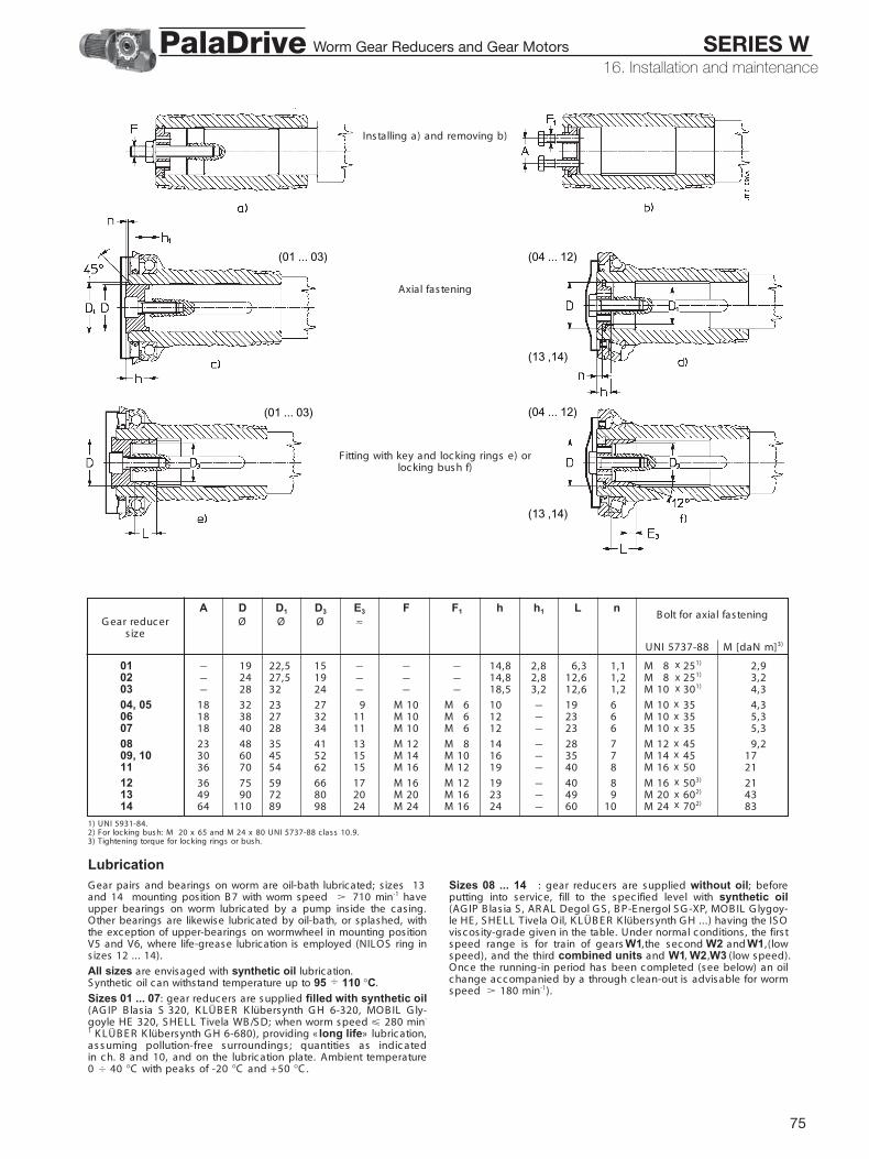
75
Installing a) and removing b)
Axial fastening
Fitting with key and loc king rings e) orloc king bush f)
(01 ... 03) (04 ... 12)
(04 ... 12)
(13 ,14)
(13 ,14)
(01 ... 03)
LubricationG ear pairs and bearings on worm are oil-bath lubricated; s izes 13and 14 mounting position B 7 with worm speed 710 min-1 haveupper bearings on worm lubricated by a pump inside the casing.Other bearings are likewise lubricated by oil-bath, or splashed, withthe exception of upper-bearings on wormwheel in mounting positionV5 and V6, where life-grease lubrication is employed (NILOS ring ins izes 12 ... 14).
All sizes are envisaged with synthetic oil lubrication.S ynthetic oil can withstand temperature up to 95 110 °C.
Sizes 01 ... 07: gear reduc ers are supplied filled with synthetic oil(AG IP B las ia S 320, K LÜB E R K lübersynth G H 6-320, MOB IL G ly-goyle HE 320, S HE LL Tivela WB /S D; when worm speed 280 min-
1 K LÜB E R K lübersynth G H 6-680), providing « long life» lubric ation,as s uming pollution-free s urroundings ; quantities as indic atedin c h. 8 and 10, and on the lubric ation plate. Ambient temperature0 40 °C with peaks of -20 °C and +50 °C .
Sizes 08 ... 14 : gear reduc ers are supplied without oil; beforeputting into servic e, fill to the spec ified level with synthetic oil(AG IP B las ia S , AR AL Degol G S , B P-E nergol S G -XP, MOB IL G lygoy-le HE , S HE LL Tivela Oil, K LÜB E R K lübersynth G H .. .) having the IS Ovisc os ity-grade given in the table. Under normal c onditions , the firs tspeed range is for train of gears W1,the sec ond W2 and W1,(lowspeed), and the third combined units and W1, W2 , W3 (low speed).Onc e the running-in period has been c ompleted (see below) an oilc hange ac c ompanied by a through c lean-out is advis able for wormspeed 180 min-1).
1) UNI 5931-84.2) For loc king bush: M 20 x 65 and M 24 x 80 UNI 5737-88 c lass 10.9.3) Tightening torque for loc king rings or bush.
A D D1 D3 E3 F F1 h h1 L nØ Ø Ø ≈ B olt for axial fastening
G ear reduc ers ize
UNI 5737-88 M [daN m]3)
01 – 19 22,5 15 – – – 14,8 2,8 6,3 1,1 M 8 251) 2,902 – 24 27,5 19 – – – 14,8 2,8 12,6 1,2 M 8 251) 3,203 – 28 32 24 – – – 18,5 3,2 12,6 1,2 M 10 301) 4,3
04, 05 18 32 23 27 9 M 10 M 6 10 – 19 6 M 10 35 4,306 18 38 27 32 11 M 10 M 6 12 – 23 6 M 10 35 5,307 18 40 28 34 11 M 10 M 6 12 – 23 6 M 10 35 5,3
08 23 48 35 41 13 M 12 M 8 14 – 28 7 M 12 45 9,2 09, 10 30 60 45 52 15 M 14 M 10 16 – 35 7 M 14 45 17 11 36 70 54 62 15 M 16 M 12 19 – 40 8 M 16 50 21
12 36 75 59 66 17 M 16 M 12 19 – 40 8 M 16 503) 21 13 49 90 72 80 20 M 20 M 16 23 – 49 9 M 20 602) 43 14 64 110 89 98 24 M 24 M 16 24 – 60 10 M 24 702) 83
16. Installation and maintenance
xxx
xxx
xxx
xxx
Worm Gear Reducers and Gear Motors SERIES WPalaDrive

76
16. Installation and maintenance
85
A mbient temperature 0 40 °C 2) – S ynthetic oilWorm speed G ear reduc er s ize
min-1
08 09 ... 12 13, 14B31), V5, V6 B6, B7, B8 B31), V5, V6 B6, B7, B8
2 800 1 400 3) 320 320 220 2201 400 1 710 3) 320 320 320 2202 710 1 355 3) 460 460 460 320
355 1 180 3) 680 680 460 460180 680 680 680
IS O visc os ity gradeMean kinematic visc os ity [c S t] at 40 °C .
1) Not s tated in name plate.2) Peaks of 10 °C above and 10 °C (20 °C for 460 c S t) below the ambient temperature
range are ac c eptable.3) For these speeds we advise to replac e oil after running-in.
Oil temperature [°C ] Oil-c hange interaval [h] - S ynthetic oil
65 18 00065 800 12 50080 950 9 000
95 110 6 300
Combined gear reducer and gearmotor units: lubrication remainsindependent, thus data relative to each s ingle gear reducer hold good.
An overall guide to oil-change interval, is given in the table, andassumes pollution-free surroundings . Where heavy overloads arepresent, halve the value.
Never mix different makes of synthetic oil; if oil-change involvesswitching to a type different from that used hitherto, then give the gearreducer a thorough c lean-out.
Running-in: a period of about 400 1 600 h is advisable, by whic htime the gear pair will have reached maximum effic ienc y (c h. 15); oiltemperature during this period is likely to reac h higher levels thanwould normally be the c ase.
Seal rings: duration depends on several fac tors suc h as draggingspeed, temperature, ambient c onditions , etc .; as a rough guide; itc an vary from 3 150 to 25 000 h.
Warning: for gear reducers s izes 08 ... 14 , befor e unscrewing thefiller plug with valve (symbol ) wait until the unit has cooled andthen open with caution.
Motor replacementAs all gearmotors are fitted with standard motors , motor replac e-ment in c ase of breakdown is extremely easy. S imply observe thefollowing instruc tions :
– be sure than the mating surfac es are mac hined under ac c urac yrating (UNE L 13501-69; DIN 42955);
– clean surfac es to be fitted, thoroughly;– c hec k and, if nec es s ary, lower the parallel key so as to leave a
c learanc e of 0,1 0,2 mm between its tip and the bottom of thekeyway; if shaft keyway is without end, lock the key with a pin;
for MW 1:– check that the fit-tolerance (push-fit) between holes hole-shaft end
is G 7/j6 for D 28 mm, F7/k6 for D 38 mm;– lubric ate surfac es to be fitted against fretting c orros ion;
for MW 2 , MW 3 :– c hec k that the fit-toleranc e (s tandard loc king) between holes and
shaft end is K 6/j6 for D 28 mm, and J 6/k6 for D 38 mm; keylength should be at least 0,9 pinion width;
– ensure that motor bearings and overhangs (dimension S ) are asshown in the table;
– mount the spacer (with rubber cement check that between keywayand motor shaft shoulder there is a grounded cylindrical part of atleast 1,5 mm) and the pinion (the latter to be preheated to a temper-ature of 80 100 °C ) on the motor, locking the assembly with either abolt to the shaft butt-end, or a stop collar;
– lubric ate the pinion toothing, and the seal ring and its rotary seat-ing with grease, assembling with extreme c are.
Shaft-mounting arrangements
Min. dynamic load c apac ity [daN] Max dimension ‘S ’Motor s ize
mm
Front R ear
63 450 335 1671 630 475 1880 900 670 20
90 1 320 1 000 22,5100 2 000 1 500 25112 2 500 1 900 28
132 3 550 2 650 33,5160 4 750 3 350 37,5180 6 300 4 500 40
200 8 000 5 600 45225 10 000 7 100 47,5
motor
groove for pullingpinion
gear reduc er
IMPOR TANT. When shaft mounted, the gearmo-tor must be supported both axially and radiallyby the shaft end of the driven mac hine, as well asanc hored against rotation only, by means of areac tion having freedom of axial movement and suffic ient clear-ance in its couplings to permit minor osc illations – always in evi-denc e – without provoking dangerous overloads on the ac tual gear-motor. Pivots and c omponents subjec t to s liding have to be proper-ly lubric ated; we rec ommend the use of a loc king adhes ive suc h asLOC TITE 601 when fitting the bolts .
The strength and shape of the c as ing offer:advantageous poss ibilities for shaft mountingeven – for instanc e – in the c ase of gearmotorwith belt drive.A few shaft mounting arrangements are shownhere with the relative details as to selec tion, andinstallation.
In c h. 17 are shown the shaft-mounting arrange-ments whic h can be supplied.
Worm Gear Reducers and Gear Motors SERIES WPalaDrive

77
S imilar to the previous arrangement fors izes 08 ... 14 (ch. 17), but us ing a fle-xible torque arm; safety devices may beinstalled to prevent acc idental overloads.The flexible torque arm may be turnedthrough 180° regardless of direction ofrotation.
R igid reac tion arrangement for variable-distanc e anc horage for s izes 04 .. . 14(c h. 17) us ing a torque arm.Where direc tion of rotation is opposite tothe one shown in the drawing, turn thetorque arm through 180°.
S emi-flexible reac tion arrangement fors izes 04 . . . 14 (c h. 17) us ing dis csprings and brac ket.
For s izes 01 .. . 10 c an be supplied (c h.17) a semi-flexible and ec onomic al reac -tion arrangement, with bolt us ing discsprings .
For the majority of normal cases , where weight force G is orthogonalor parallel to reaction R R as illustrated in the drawings , reactions arecalculated thus :
BA
– G [daN]: weight force almost equal numerically to gearmotor mass(c h. 10);
– M2 [daN m]: output torque expressed by + or – ac c ording to thedirec tion of rotation in the drawing;
– x [m]: dimension to x = G + 0,2 · Y (ch. 10);– y [m]: dimension y = 0,5 · B + (c h. 10);– xR [m]: dimension xR = 0,5 · A (drawing on the left) or xR = H + S
(drawing on the right) (c h. 10 and 17);– l, s [m]: dimension s must be the shortest poss ible;
1) reac tion R R produc ed by support R :
[daN]
2) bending moment MfA through the c ross-section of bearing A:
MfA = [G · (y + s )]2 + [R R · s ]2 [daN m]
3) radial reac tion R A produc ed by bearing A:
R A = [G · (y + s + l)]2 + [R R · (s + l)]2 [daN]
4) radial reac tion R B produc ed by bearing B :
[daN]
1l
B
B
R R = (1 / xR) · [G · x + (± M2)]
R B = MfA
l
16. Installation and maintenanceWorm Gear Reducers and Gear Motors SERIES WPalaDrive

78
Strengthened high speed shaft bearingsG ear reduc ers W 2 s izes 06 .. . 10 with iN 160 c an be suppliedwith c ylindric al roller bearings supporting the high speed shaftallowing inc reased radial loads , values x 1,6 for s izes 06 .. . 08 , x1,4 for s izes 09 and 10 (c h. 13); this des ign is s tandard for s izes11 . . . 14.
S upplementary desc ription when ordering by designation: streng-hened high speed shaft bearing.
Low speed shaftsS upplementary description when ordering by designation: stan-dard, or double extension low speed shaft.
D E D1 h L1 L2 l 2 Z ViteØ Ø B olt MassG ear
[kg]reduc ers ize
UNI 5737-88 S tandard
Double ext.
01 19 h7 30 28 4 108 138 36 78 M 6 20 0,3 0,402 24 h7 36 35 5 128 164 45 92 M 8 25 0,6 0,703 28 h7 42 35 5 148 190 63 106 M 8 25 0,8 1
04, 05 32 h7 58 47 5 184 242 70 126 M 10 30 1,2 1,506 38 h7 58 47 5 208 266 90 150 M 10 30 1,9 2,407 40 h7 58 47 5 208 266 90 150 M 10 30 2,1 2,7
08 48 h7 82 57 6 262 344 110 180 M 12 40 3,7 4,9 09, 10 60 h7 105 82 8 317 422 140 212 M 16 45 7 9,4 11 70 j6 105 82 8 355 460 180 250 M 16 45 11 14
12 75 j6 105 82 8 355 460 180 250 M 16 45 12,6 16 13 90 j6 130 102 10 430 560 200 300 M 20 60 21 28 14 110 j6 165 135 12 525 690 250 360 M 24 60 39 51
Solid low speed shaft (s ize 14 )In order to permit the high radial loads given in the ca-talogue (14 bis ), the gear reducer s ize 14 can be sup-plied with solid low speed shaft and strengthened bear-ings. Dimensions remain unchanged (miss ing the washeron shaft end).
S upplementary desc ription when ordering by designa-tion: solid low speed shaft pos. 1 or 2 or doubleextension.
Oversized hollow low speed shaftThe gear reduc ers and gearmotors s izes 01 . . . 05 and 100 c an be sup-plied with overs ized hollow low speed shaft; dimensions are ac c ordingto table on the left.
S upplementary desc ription when ordering by designation: over-sized hollow low speed shaft.
FlangeAll gear reduc ers and gearmotors c an be supplied with B5 flangehaving c learanc e holes and spigot « rec ess» .Loc king adhes ives s uc h as LOC TITE are rec ommended botharound threads and on mating surfac es .
S upplementary description when ordering by designation: flange B5.
F G H1 H2 M N P Q S V ZØ Ø Ø Ø Ø / MassG ear
kgreduc ers ize
h12 h12 H7
01 27 55 34,5 71 100 80 120 4 10 95 39 0,502 29,5 68 41,5 80 115 95 140 4 11 110 46 0,803 29,5 85 49 80 130 110 160 4,5 12 125 53 1
04, 05 11,5 80 58,5 100 165 130 200 4,5 14 152 63 206, 07 14 110 69,5 112 215 180 250 5 16 196 75 3,2
08 14 130 84,5 132 265 230 300 5 18 248 90 5,5
09, 10 188 180 99,5 150 300 250 350 6 20 290 106 8,5 11, 12 188 230 118,5 180 350 300 400 6 22 350 125 13 13 18 8 250 137,5 200 400 350 450 6 22 – 150 20
14 22 8 350 163 236 500 450 550 6 25 – 180 31
The shoulder outer diameter of the part, or of spac er abutting with the gear reduc er mustbe (1,25 1,4) · D.
D Linguetta C avaØ Parallel key K eywayG ear
b x h x l* b t t1reduc er s ize
H7
01 20 6 6 36 6 41) 22,21)
02 25 8 7 45 8 4,51) 27,71)
03 30 8 7 63 8 51) 32,21)
042), 052) 35 10 8 90 10 61) 37,31)
08 50 14 9 110 14 5,51) 53,81)
Strengthened low speed shaft bearingsG ear reducers and gearmotors s izes 04 .. . 10 can be supplied withtaper roller bearings supporting the low speed shaft, allowingincreased radial and/or axial loads. Values for s izes 08 ... 10 aregiven in ch. 14, other values , consult us .S upplementary des c ription when ordering by designation:strengthened low speed shaft bearings.
01 ... 12
13 ... 14
17. Accessories and non-standard designs
17. Accessories and non-standard designs
F G H1 H2 M N P Q S V ZØ Ø Ø Ø Ø / MassGear
kgreducersize
h12 h12 H7
01 27 55 34,5 71 100 80 120 4 10 95 39 0,502 29,5 68 41,5 80 115 95 140 4 11 110 46 0,803 29,5 85 49 80 130 110 160 4,5 12 125 53 1
04, 05 11,5 80 58,5 100 165 130 200 4,5 14 152 63 206, 07 14 110 69,5 112 215 180 250 5 16 196 75 3,2
08 14 130 84,5 132 265 230 300 5 18 248 90 5,5
09, 10 188 180 99,5 150 300 250 350 6 20 290 106 8,5 11, 12 188 230 118,5 180 350 300 400 6 22 350 125 13 13 188 250 137,5 200 400 350 450 6 22 – 150 20
14 228 350 163 236 500 450 550 6 25 – 180 31
Worm Gear Reducers and Gear Motors SERIES WPalaDrive

79
Controlled or reduced backlashG ear reducers and gearmotors with worm gear pair controlled orreduced backlash.Values are 1/2 (controlled backlash) or 1/4 (reduced backlash) thosestated on ch. 15; reduced backlash designed not poss ible for W 1and MW 1 with input speed n1 1 400 min-1.S upplementary description when ordering by designation: control-led backlash or reduced backlash.
Square flange for servomotorsMW 1 and MW 012... 072 gearmotors c an be supplied with motormouting flange when c oupling with servomotors and, only for MW1,with hub c lamp for fitting with key between gear reduc er worm shaftand motor shaft; for MW 2 firs t reduc tion pinion keyed direc tly ontomotor shaft end permits to avoid bac klash and consequently shoc kon the same keying.
C onsidering that servomotors do not have any standardised dimen-s ions , when selecting verify all c oupling dimensions stated in thetable; d dimension determines IE C stardardised motor s ize in c ata-logue gearmotor des ignation (see c h. 3 and 9).For other gearmotor dimensions see c h. 10.In c ase of motor removing, firs t loos en the hub c lamp.For the verifications of keying, motor mounting flange and motorbearing res is tanc e ac c ording to motor performanc es , speed, massand length, consult us.Controlled or reduced backlash design c an be supplied (seec h.15 and pag. 88).S ervogearmotors c omplete with sync hronous « brushless» and asyn-c hronous « vec tor» motors des igned for automation: see c at. S R .S upplementary desc ription when ordering by designation: squareflange ... – ... (s tate V1 – d dimension; e.g.: 145-24).
Gearmotor with interposed couplingG earmotors MW 111 .. . 141 c an be supplied with a c oupling readyfitted between gear reduc er and motor. This may be a s teel/plasticserrated c oupling or a flexible c oupling.This kind of gearmotor utilizes UO2B gear reduc er des ign (withreduc ed wormshaft end) to whic h a flange, a spac er and then the c ou-pling are added, in addition to the motor itself.S upplementary desc ription when ordering by designation (the sameas for gearmotors in c h. 9): gearmotor with coupling or with flexiblecoupling.
V1 F K M1 N1 P1 Q1 S d eØ Ø Ø Ø ØG ear reduc er
H7s ize1)
01 90 M 6 7 100 80 120 4 9,5 11 23
90 M 64 – 100 80 120 4 9 11 2302, 03 14 30
19 40
105 M 84 9,54 115 95 140 4 11 14 302) 19 40
120 – 9,54 130 110 160 4,5 11 19 40
04 ... 07 105 M 84 – 115 95 140 4 10 14 3019 40
3) 120 M 84 9,54 130 110 160 4,5 12 19 4024 50
145 – 11,54 165 130 195 4,5 12 19 4024 5028 60
G randezza - S ize
gear reduc er motorG
11, 12 180 330
13 180, 200 375
14 180, 200 440225, 250 B5R 470
.
1) Working length of thread 1,5 · F.2) For s ize 40, d = 11 and 14 only.3) For s ize 63 and 64 with V1 = 145 d = 24
only.
17. Accessories and non-standard designs
V1 F K M1 N1 P1 Q1 S d eØ Ø Ø Ø ØGear reducer
H7size1)
01 90 M 6 7 100 80 120 4 9,5 11 2390 M 64 – 100 80 120 4 9 11 23
02, 03 14 3019 40
105 M 84 9,54 115 95 140 4 11 14 302) 19 40
120 – 9,54 130 110 160 4,5 11 19 4004 ... 07 105 M 84 – 115 95 140 4 10 14 30
19 403) 120 M 84 9,54 130 110 160 4,5 12 19 40
24 50145 – 11,54 165 130 195 4,5 12 19 40
24 5028 60
1) Working length of thread 1,5 · F.2) For size 40, d = 11 and 14 only.3) For size 63 and 64 with V1 = 145 d = 24
only.
Worm Gear Reducers and Gear Motors SERIES WPalaDrive

80
It is better if this arrangement is applied on s ides 1.
S upplementary desc ription when ordering by designation: reac-tion bolt using disc springs.
S upplementary desc ription when ordering by designation: reac-tion bolt using disc springs and bracket.
S upplementary desc ription when ordering by designation: rigid(for torque arm pos itioning, see c h. 16) or flexible torque armusing bracket.
Hollow low speed shaft washerAll gear reduc ers and gearmotors c an be supplied with washer, c ir-c lip (exc luding s izes 01 .. . 03), bolt for axial fastening and protec tionc ap (c h. 16).
S upplementary desc ription when ordering by designation: hollowlow speed shaft washer.
Shaft-mounting arrangementsS ee tec hnic al explanations at c h. 16.
For dimensions A, B see c h. 8 and 10.
T F R M2B olt Disc spring Ø 1) 2)
G earreduc er
s ize
UNI 5737-88 DIN 2093 daN m
01 M 6 x 40 A 18 n. 2 8 10 8 4,9 –02 M 8 x 55 A 25 n. 2 10 14 11 6,5 –03 M 8 x 55 A 25 n. 2 10 14 11 6,5 20
04, 05 M 12 x 70* A 35,5 n. 2 14 17 20 8,8 31,506, 07 M 12 x 90 A 35,5 n. 3 18 25 16 10,8 56
08 M 16 x 110 A 50 n. 2 23 32 20 13,1 100
09, 10 M 16 x 110 A 50 n. 2 23 32 20 13,1 160
1) Theoretic al value: toleranc e 0 -1.2) For higher M2 values , utilize 2 reac tion
bolts or the arrangement with brac ket(see below).
* Modified bolt.
T F S U RB olt Disc spring Ø 1)G ear
reduc ers ize
UNI 5737-88 DIN 2093
04, 05 M 12 x 70* A 35,5 n. 1 14 17 20 38 23 6,806, 07 M 12 x 90 A 35,5 n. 2 18 25 20 38 23 8,8
08 M 16 x 110 A 50 n. 2 25 32 20 50 30 13,1
09 M 16 x 110 A 50 n. 2 25 32 20 50 30 13,1 11, 12 M 20 x 130 A 63 n. 3 23 38 24 65 40 17,9 13 M 24 x 160 A 80 n. 2 29 48 30 80 48 20,7
14 M 30 x 200 A 100 n. 2 37 60 36 100 40 26,2
1) Theoretic al value: toleranc e 0 -1.* Modified bolt.
f O S L X Y Z lØ Ø ≈G ear
reduc ers ize
04, 05 12 280 350 38 14 – – – 5006, 07 12 280 350 38 14 – – – 56
08 16 410 510 50 17 52 242 84 74
09 16 410 510 50 17 52 242 84 74 11, 12 22 580 680 65 24 64 285 147 92 13 28 580 680 80 30 88 305 137 113
14 28 580 680 100 30 88 305 137 141
17. Accessories and non-standard designs
f O S L X Y Z lØ Ø ≈Gear
reducersize
04, 05 12 280 350 38 14 – – – 5006, 07 12 280 350 38 14 – – – 56
08 16 410 510 50 17 52 242 84 74 09 16 410 510 50 17 52 242 84 74 11, 12 22 580 680 65 24 64 285 147 92 13 28 580 680 80 30 88 305 137 113 14 28 580 680 100 30 88 305 137 141
f O S L X Y Z lØ Ø ≈Gear
reducersize
04, 05 12 280 350 38 14 – – – 5006, 07 12 280 350 38 14 – – – 56
08 16 410 510 50 17 52 242 84 74 09 16 410 510 50 17 52 242 84 74 11, 12 22 580 680 65 24 64 285 147 92 13 28 580 680 80 30 88 305 137 113 14 28 580 680 100 30 88 305 137 141
Worm Gear Reducers and Gear Motors SERIES WPalaDrive

81
Hollow low speed shaft washer with locking ringsor bushAll gear reduc ers and gearmotors c an be supplied with washer, c ir-c lip (exc luding s izes 01 .. . 03), loc king rings (s izes 01 .. . 03) or loc k-ing bush (s izes 04 ... 14 ), bolt for axial fastening and protec tionc ap (c h. 16).
S upplementary desc ription when ordering by designation: hollowlow speed shaft washer with locking rings or bush.
Hollow low speed shaft protectionG ear reduc ers and gearmotors , s izes 01 .. . 12 , c an be suppliedwith only the protec tion c ap for the area not utilized by the hollow lowspeed shaft (c h. 16).
S upplementary desc ription when ordering by designation: hollowlow speed shaft protection.
Gear reducer design ATEX II 2 G/D and 3 G/DWorm gear reduc ers may be supplied ac c ording to E uropean C om-munity Direc tive ATE X 94/9/E C in order to be used in potentiallyexplos ive atmospheres of c ategory 2 G/D (for operation in zones1 (G = gas ), 21 (D = dus t): pres enc e of probable explos ive atmo-s phere) and 3 G/D (for operation in zones 2 (G = gas ) 22 (D =dus t): pres enc e of improbable explos ive atmos phere) with s urfac etemperature 135 °C (T4).Thes e are the main variations of the produc t:– Viton® seal rings ;– metal plugs ;– absenc e of plastic parts ;– spec ial name plate with ATE X mark and indic ation of applic ation limits ;For c ategory 2 G /D also:– double seal rings on low speed shaft;– thermal probes for monitoring temperature of oil and/or bearings ,
if any (see end of paragraph) or thermostats for the c ontrol ofmaximum oil temperature.
The Atex installation and maintenance handbook (with the addi-tional doc umentation, if any) is integral part of the supply of eac hgear reduc er; every indic ation s tated in it mus t be c arefully applied.In c as e of nec es s ity c ons ult us .
Selection of products of category 2 G/D and 3 G/DDetermine the s ize of gear reduc er as indic ated in c h. 6 c ons ideringfollowing additional indic ations :a) maximum input speed n1 1 500 min-1.
b) service factor requested determined ac c ording to c h. 5 inc rea-sed with the factors s tated in table 1 - never lower than 0,85.
Verify thermal power P t bas ing on: P tN (see tab. pag. 92), c orrec ti-ve fac tor (s ee table 2) and c orrec tive fac tors of c atalogue (see c h.4).
Additional desc ription when ordering by designation:Design ATEX II 3 G/D T4 or ATEX II 2 G/D T4Optional sensors (thermal probes or thermostats ) may be availablein order to reduc e the interval of c ontrols : this solution is advisablewhen the gear reduc er or gearmotor has diffic ult ac c ess .Minimum c ontrol intervals :– 1 month without optional sensors ;– 3 month with optional sensors .For more information see the installation and maintenanc e hand-book U.T.D 123 and/or c onsult us .
Table 1. Corrective factor fs
2 G/D 3 G/D
C orrec tive fac tor offs required 1,25 1,12
Table 2. ft corrective factor for Pt
2 G/D 3 G/D
C orrec tive fac tor offt (thermal power) 0,8 0,9
17. Accessories and non-standard designsWorm Gear Reducers and Gear Motors SERIES WPalaDrive

82
1) For worm speed nxintemediate between two stated values (nsup, ninf), selec t the nearestlower value or interpolate.
2) For nworm 90 min-1, c onsult us .
grand. 04, 05
grand. 01
grand. 03
grand. 06, 07 grand. 08
grand. 11, 12grand. 09, 10
grand. 13
P tN for gear reducers and gearmotors
7 10 13 16 20 25 32 40 50 63
grand. 02
7 10 13 16 20 25 32 40 50 63 7 10 13 16 20 25 32 40 50 63
7 10 13 16 20 25 32 40 50 63 7 10 13 16 20 25 32 40 50 63
nvite2)
worm
min-1
nvite2)
worm
min-1
1 400 4,15 3,59 3,04 2,82 2,58 2,1 1,83 1,66 1,49 1,321 120 3,82 3,28 2,76 2,54 2,34 1,82 1,65 1,5 1,35 –
900 3,51 2,99 2,51 2,31 2,11 1,65 1,49 1,36 1,23 –
710 3,17 2,7 2,27 2,09 1,91 1,49 1,35 1,23 1,11 –560 2,89 2,46 2,06 1,89 1,75 1,36 1,22 1,13 – –450 2,67 2,28 1,9 1,75 1,61 1,24 1,13 1,05 – –
355 2,47 2,09 1,73 1,6 1,49 1,14 1,04 – – –280 2,31 1,94 1,61 1,49 – 1,06 0,96 – – –224 2,11 1,8 1,5 – – 0,99 – – – –
180 1,98 1,69 1,4 – – – – – – –140 1,8 – – – – – – – – –112 – – – – – – – – – –
7 10 13 16 20 25 32 40 50 63
7 10 13 16 20 25 32 40 50 63 7 10 13 16 20 25 32 40 50 63
7 10 13 16 20 25 32 40 50 63
1 400 – 9,8 8,5 7,8 7,2 5,7 5,1 – – –1 120 – 8,5 7,3 6,6 6,2 4,84 4,32 – – –
900 – 7,2 6,2 5,6 5,3 4,12 3,67 3,4 – –
710 – 6,2 5,3 4,8 4,45 3,5 3,11 2,87 – –560 – 5,3 4,49 4,08 3,79 2,97 2,64 2,44 – –450 – 4,59 3,9 3,54 3,3 2,56 2,3 – – –
355 – 4,02 3,41 3,09 2,89 2,24 2,01 – – –280 – 3,55 3,01 2,76 2,57 1,99 1,79 – – –224 – 3,18 2,69 2,44 – 1,78 1,59 – – –
180 – 2,88 2,42 2,21 – 1,6 – – – –140 – 2,52 2,12 – – 1,4 – – – –112 – 2,25 1,9 – – – – – – –
grand. 14
1 400 – – – 48,5 41,2 39,4 35,5 27,3 25,7 23,21 120 – – – 42,2 36 34 30,2 23,8 22,1 19,7
900 – – – 36,8 31 29,6 25,9 20,4 18,9 16,8
710 – – – 31,2 26,4 25 22,2 17,3 16 14,4560 – – – 26,9 22,8 21,4 18,8 14,9 13,6 12,2450 – – – 23,4 19,7 18,6 16,3 12,8 11,8 10,6
355 – – – 20,2 17 15,9 14 11 10,1 9,1280 – – – 17,7 14,9 14 12,3 9,6 8,9 8224 – – – 15,8 13,1 12,4 11 8,5 7,9 7,2
180 – – – 14,2 11,8 11,1 9,8 7,7 7,1 6,4140 – – – 12,5 10,3 9,8 – 6,7 6,2 –112 – – – 11 9,1 8,6 – 5,9 5,6 –
90 1) – – – 9,9 8,3 7,8 – 5,4 5 –
1 400 – – 33,1 31,3 27 25,1 19,4 17,7 16,2 14,51 120 – – 28,6 26,9 23,2 21,5 16,7 15 13,9 12,3
900 – – 24,7 23,1 20 18,3 14,5 12,8 11,7 10,5
710 – – 21,2 19,9 17 15,7 12,2 10,9 10 8,9560 – – 18,2 17 14,5 13,4 10,4 9,3 8,5 7,6450 – – 15,8 14,7 12,6 11,6 9 8 7,3 6,5
355 – – 13,7 12,7 10,8 10 7,7 6,9 6,3 5,7280 – – 12 11,2 9,5 8,8 6,8 6,1 5,6 –224 – – 10,7 10 8,5 7,8 6 5,4 5 –
180 – – 9,6 9 7,6 7 5,4 4,85 4,52 –140 – – 8,4 7,8 6,6 6,1 4,74 4,25 3,93 –112 – – 7,5 7,1 5,9 5,5 4,17 3,83 – –
901) – – 6,8 6,3 5,3 4,93 3,79 3,46 – –
1 400 – 15,2 14 12,2 11,2 10,4 8 7,1 6,6 5,91 120 – 13,1 11,9 10,3 9,5 8,8 6,7 6 5,6 –
900 – 11,3 10,2 8,9 8,1 7,5 5,8 5,1 4,76 –
710 – 9,6 8,7 7,5 6,9 6,4 4,89 4,36 4,03 –560 – 8,3 7,4 6,4 5,8 5,4 4,17 3,7 3,44 –450 – 7,2 6,4 5,6 5,1 4,7 3,6 3,21 2,99 –
355 – 6,2 5,6 4,81 4,4 4,11 3,12 2,81 – –280 – 5,5 4,99 4,27 3,92 3,64 2,77 2,49 – –224 – 4,91 4,46 3,81 3,49 3,24 2,48 2,23 – –
180 – 4,42 3,98 3,4 3,11 – 2,21 2,01 – –140 – 3,9 3,51 3,01 2,75 – 1,97 – – –112 – 3,48 3,14 2,68 – – 1,75 – – –
90 1) – 3,14 2,85 – – – – – – –
1 400 – 23,4 21,8 18,9 17,4 16,1 12,5 11,4 10,3 9,31 120 – 20,2 18,9 16,3 14,9 13,8 10,8 9,7 8,7 7,8
900 – 17,4 16,1 13,9 12,7 11,8 9,1 8,3 7,5 6,7
710 – 15 13,8 11,8 10,8 10 7,7 7 6,3 5,7560 – 12,8 11,8 10,1 9,2 8,5 6,6 6 5,4 4,82450 – 11,1 10,2 8,7 8 7,4 5,7 5,1 4,67 4,17
355 – 9,6 8,8 7,5 6,9 6,4 4,81 4,44 4,05 3,65280 – 8,5 7,8 6,7 6,1 5,6 4,32 3,94 3,6 –224 – 7,6 7 5,9 5,4 5 3,86 3,51 3,23 –
180 – 6,9 6,3 5,4 4,86 4,49 3,48 3,16 2,89 –140 – 6 5,5 4,63 4,26 – 3,02 2,78 2,32 –112 – 5,4 4,92 4,16 3,81 – 2,71 2,5 – –
90 1) – 4,81 4,42 3,74 3,43 – 2,46 2,25 – –
1 400 1,14 0,93 0,84 0,77 0,6 0,55 0,49 – – –1 120 1,04 0,84 0,76 0,69 0,55 0,49 0,45 – – –
900 0,94 0,76 0,7 0,64 0,5 0,46 – – – –
710 0,87 0,7 0,63 0,58 0,45 0,41 – – – –560 0,8 0,64 – – 0,41 – – – – –450 – – – – 0,38 – – – – –
1 400 1,72 1,4 1,29 1,18 0,92 0,84 0,76 0,68 – –1 120 1,58 1,28 1,16 1,06 0,83 0,76 0,68 0,62 – –
900 1,43 1,16 1,05 0,96 0,75 0,69 0,63 – – –
710 1,31 1,05 0,96 0,88 0,69 0,63 0,57 – – –560 1,2 0,96 0,88 0,81 0,63 0,58 – – – –450 1,1 0,89 0,82 0,75 0,58 0,54 – – – –
355 1,01 0,81 – – 0,53 – – – – –280 – – – – 0,5 – – – – –
1 400 2,73 2,34 1,97 1,81 1,67 1,3 1,17 1,08 0,96 –1 120 2,49 2,13 1,79 1,64 1,5 1,17 1,06 0,97 – –
900 2,28 1,93 1,62 1,48 1,37 1,06 0,95 0,88 – –
710 2,07 1,75 1,46 1,34 1,24 0,96 0,87 – – –560 1,9 1,61 1,34 1,23 – 0,88 0,8 – – –450 1,76 1,48 1,24 1,14 – 0,82 – – – –
355 1,62 1,37 1,13 1,04 – 0,74 – – – –280 1,51 1,27 1,06 – – – – – – –
7 10 13 16 20 25 32 40 50 63
1 400 0,82 0,67 – – 0,44 – – – – –1 120 – 0,61 – – 0,4 – – – – –
900 – – – – – – – – – –
710 – – – – – – – – – –560 – – – – – – – – – –450 – – – – – – – – – –
u viteworm
u viteworm
nvite2)
worm
min-1
u vitewormnvite
2)
worm
min-1
u viteworm
nvite2)
worm
min-1
nvite2)
worm
min-1
u viteworm
u viteworm
nvite2)
worm
min-1
u vitewormnvite
2)
worm
min-1
nvite2)
worm
min-1
u viteworm
u vitewormnvite
2)
worm
min-1
u viteworm
17. Accessories and non-standard designsWorm Gear Reducers and Gear Motors SERIES WPalaDrive

83
– – motor featuring: d.c . supply; s ingle-phase; explos ion-proof; withsecond shaft end; with non-standard protec tion, voltage andfrequenc y; provided with devic es against overloads and over-heating;
– – motor without fan c ooled by natural convection (s ize 63 .. .112); des ign for textile industry.
– G ear reduc ers and gearmotors with mechanical torque limiteron output shaft, gear reducer s izes 01 ... 11 (exc luding s ize 81).
– G ear reduc er des ign with mec hanic al friction type torque limiter(fric tion surfac es without asbestos), c ompac t and with high trans-miss ible torque – up to 300 daN m – and top quality s tandards .
– It protects the drive from accidental overloads by exc luding theeffect of intertia loads transmitted from up-line masses and, also ifthe gear reducer is irrevers ible (the torque limiter being mounted onthe output shaft), inertia loads transmitted from down-line masses .
– When the transmitted torque tends to exc eed the setting value thedrive « s lips» although it remains engaged with torque equal tothe limiter setting value; s lipping stops as soon as the load returnsto normal; in the c ase of very brief overloads the driven mac hinewill c ontinue normal operation (after dec elating or s topping) with-out requiring reset proc edures .
Miscellaneous– E xpansion tank for c ontinuous duty and high speed running of
gear reduc ers and gearmotors W 2 08 ... 14 and W 3 08 ... 10mounting pos ition B6.
– G ear reduc ers and gearmotors s izes 08 ... 14 supplied filledwith synthetic oil.
– G earmotors with:– – HFV (also s ingle-phase) brake motor with d.c . safety and/or
parking brake (s izes 63 .. . 132) having overall dimensionsnearly the same of a standard motor and braking torque Mf MN,maximum ec onomy;
– – two-speed motor, HF standard motor, F0 and HFV brakemotors : 2.4, 2.6, 2.8, 2.12, 4.6, 4.8, 6.8 poles ;
– – FV0 brake motor for traverse movements: 2, 2.4, 2.6, 2.8,2.12 poles (always with low noise d.c . brake, see pic ture);
Motors: the following table c ontains the minimum requirementsnec essary for motors to be installed with gear reduc ers in areaswith potentially explos ive athmospheres and motors whic h c an besupplied by R oss i Motoriduttori.
Zone Required category of equipment1) Motor supplied by Rossi Motoriduttori
Gear reducer Motor Standard With brake
1
212
22
2 G /D3)
3 G /D
2 G E E xe2 G E E xd2 G E E xde
2 D IP65
3 G E E xn3 D IP542)
with thermistors orP t100
–
2 G /D E E xd IIB T4 (135°C ) 2 G /D E E xd4) IIB T4 (135°C )
3 D 135°C IP555)
1) The devic es suitable for zone 1 are also suitable for zone 2; s imilarly the devic es suita-1) ble for zone 21 are also suitable for zone 22.2) For c onduc tive dusts motor must be 2 D IP65.3) Whenever the level switc h is present, the c ategory will be 2G there fore the gear reduc er
is not suitable for zone 21.4) Also E E xde available.5) It c annot be supplied with independent c ooling fan.
c onsult us
17. Accessories and non-standard designsWorm Gear Reducers and Gear Motors SERIES WPalaDrive

84
MLS / MLA
mounted between gear r
e
duc erand motor or motor-variator
MLS / MLA
mounted onto c ombined units
MLAfric tion
MLSballs
* on request
****
– Hollow low speed shaft with ac me-type thread.
– G earmotors with interpos ed c ompac t c lutc h-brake or fluidc oupling/brake unit.
– S emi-flexible and hydrodynamic couplings .– S pec ial paint options :– – external, single-compound: antirus t zinc primer plus blue
R AL 5010 DIN 1843 synthetic paint (exc luding s izes 01 .. . 07);– – external, dual-compound: dual-c ompound epoxy-polyamidic
antirus t primer plus dual-c ompound blue R AL 5010 DIN 1843polyurethane enamel (exc luding s izes 01 .. . 07).
– S pec ial seal rings ; double seal (exc luding s izes 01 .. . 03).– For high transmiss ion ratios combined units can be also obtained
with initial gearmotor MW 012 with final gear reduc er s ize 81andwith initial gearmotor MW 013 for final gear reduc er s ize 100.
The system, as the unit is mounted externally to the gear pair, will notafter if the direc tion of rotation c hanges and it does not affec t therigidity and meshing prec is ion between worm and worm wheel(this is important to ensure the c orrec t transmiss ion of torque andthe limitation of undue bac klash between teeth through time). Thesystem also permits shaft mounting with the limiter mounted ex-ternally (eas ily access ible) or in the intermediate position (bettersafety protec tion). It c an be interposed, in the combined units,between initial worm gear reduc er and final worm gear reduc er,s izes 08 ... 14 .
On reques t s lide detec tor. For more details s ee specific literature.
– MLA and MLS unit, mechanical torque limiter on input shaft,motor s izes 80 ... 200 (180 for MLS ).
– Mec hanic al torque limiter unit to be interposed between gearreduc er and B 5 mounting pos ition motor s tandardized to IE C or(wide belt or planetary motor-variator) or, in combined units, bet-ween the initial gear reduc er and the final worm gear reduc er,s izes 03 ... 14 .
– Axially ultra-c ompac t des ign: exc ellent load bearing with life lubri-cated double row angular contact ball bearings (motor s ize 112)or « O» disposed taper roller bearings .
– The unit protec ts the drive from ac c idental overloads by exc ludinginertia loads trasmitted from up-line masses and if the gear redu-c er is revers ible (the torque limiter being on the input shaft), iner-tia loads transmitted from down-line masses .
– LA unit is friction type (fric tion surfac es without asbestos).When the transmitted torque tends to exc eed the setting, the drive« s lips» although it remains engaged and transmits torque equalto the limiter setting value; s lipping stops as soon as the loadreturns to normal; in the c ase of very brief overloads the drivenmac hine will c ontinue normal operation (after dec elerating orstopping) without requiring reset proc edures .
– LS unit is ball type. When the transmitted torque tends to exc eedthe setting, the drive is « disengaged» so it does not remainc onnec ted. The driven mac hine will therefore stop.
– LA and LS units are mec hanic ally interc hangeable. On requests lide detec tor. For more details see specific literature.
E xternal limiter mounting Intermediate limiter mountingLimiter mounting onto
c ombined units
on request on request
17. Accessories and non-standard designsWorm Gear Reducers and Gear Motors SERIES WPalaDrive

Worm Gear Reducers and GearMotors NOTEPalaDrive
85

Worm Gear Reducers and GearMotors NOTEPalaDrive
86


![Motoriduttori pendolari Helical parallel gearmotors · 2016-06-21 · Motoriduttori pendolari Helical parallel gearmotors. D1 oriduttotM FT H ors FT 0616A Pagina / Page ... [Hz] Frequenza](https://static.fdocuments.in/doc/165x107/5e308a03da4cf45f607b3a28/motoriduttori-pendolari-helical-parallel-2016-06-21-motoriduttori-pendolari-helical.jpg)