Workload distribution in satellites Final Presentation Performed by :Grossman Vadim Maslovksy Eugene...
32
Workload distribution in satellites Final Presentation Performed by : Grossman Vadim Maslovksy Eugene Instructor: Rivkin Inna Spring 2004
-
date post
21-Dec-2015 -
Category
Documents
-
view
214 -
download
0
Transcript of Workload distribution in satellites Final Presentation Performed by :Grossman Vadim Maslovksy Eugene...
Workload distribution in satellitesFinal Presentation
Performed by : Grossman Vadim
Maslovksy Eugene
Instructor: Rivkin Inna
Spring 2004

An introduction
Several I/O peripherals require lots of “attention”
Degrading the overall performance
Some systems should prioritize computational power over I/O latency
We were appointed to design a system that would enable that
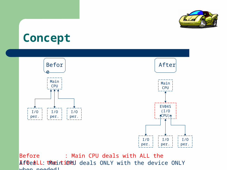
Concept
Before
Main CPU
I/O per.
I/O per.
I/O per.
Before : Main CPU deals with ALL the I/O ALL the time!
After
EV04S (I/O CPU)
Main CPU
I/O per.
I/O per.
I/O per.
After : Main CPU deals ONLY with the device ONLY when needed!

What can we improve?
Implement the I/O protocols elsewhere– Using an I/O CPU
Reduce the number of distractions– Less interrupts– I/O CPU polling– Using Buffers

The chosen solution
Advantages:– Faster access from the PPC– Less load on the busses
Disadvantages:– More complex design– More hardware needed
PLB OPB
Main CPU
I/O CPU
PLB2OPB
EV04S

Multiple devices
How about several I/O peripherals?
A unified device1) Use one “communication line” and protocol
Several devices2) A device for each peripheral
3) Groups of 3 on a single IPIF
The 2nd and 1st solutions were implemented

Architecture diagram
DLMB
PPCPPC
MBMB I/O #1 I/O #2 I/O #3
OPB
PLB
Bram + Controller
PLB2OPB
ILMB
Bram + Controller
EV04SEV04SEV04SEV04S
MB Intc PPC Intc
EV04SEV04S

Deeper and deeper
IPIFIPIF
IPIFIPIF
Control Control UnitUnit
Buffers Buffers UnitUnit
OPB
PLB
PPC int.
MB int.
64 bits
32 bits

The buffers
FIFO
FIFO
64 bits
32 bits
32 bits
MUX32 bits
Co
ntro
l in
Asynchronous FIFO cores Double FIFO sets + a mux \ switch
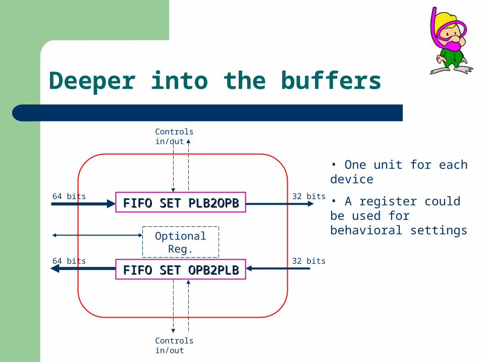
Deeper into the buffers
• One unit for each device
• A register could be used for behavioral settingsFIFO SET PLB2OPB FIFO SET PLB2OPB
FIFO SET OPB2PLB FIFO SET OPB2PLB
Controls in/out
Controls in/out
64 bits
64 bits
32 bits
32 bits
Optional Reg.

Deeper into the controls
PLB
Controller
FIFO SET PLB2OPBFIFO SET PLB2OPB
FIFO SET OPB2PLBFIFO SET OPB2PLB
OPB
Controller
OPB clkR_req
W_req
Ack
Err
Busy
PLB clk
R_reqW_req
AckErr
Busy
PLB clk OPB clk
PLB clk OPB clk
W_
en
Ack
/Err
Fu
ll
Co
un
twrite read
R_
en
Ack
/Err
Em
pty
Co
un
t
W_
en
Ack/E
rr
Fu
ll
Co
un
t
writeread
R_
en
Ack/E
rr
Em
pty
Co
un
t
MB int. PPC int.
PLB
IPIF
PLB
IPIF
OP
B IP
IFO
PB
IPIF
RetryWait
Empty Empty

Deeper into the FIFO set
FIFO 1FIFO 1
FIFO 2FIFO 2
64 bits
32 bits
32 bits
MUX32 bits
ControllerPLB2OPB set
R_en 1
R_en 2
W_en
MUX
From each FIFO
OPB clk
PLB clk
R_en
W_en
From upper level
R_
ack
W_
ack
Fu
ll
Em
pty
To upper level
Counter
R_
ack
W_
ack
Fu
ll1
Em
pty
Counter
ControllerThe controller:
• Create multiple control signals
• Manage the read switching
Controller

Deeper into the FIFO set
FIFO 1FIFO 1
FIFO 2FIFO 2
64 bits
32 bits
32 bits
DEC32 bits
ControllerOPB2PLB set
ControllerThe controller:
• Create multiple control signals
• Manage the write switching
Controller
OPB clk
PLB clk
W_en
R_en
From upper level
R_
ack
W_
ack
Fu
ll
Em
pty
To upper level
Counter
From each FIFO
R_
ack
W_
ack
Fu
ll1
Em
pty
Counter
W_en 1
W_en 2
R_en
MUX

Implemented buffers
VHDL
HDLDesigner– State machines– Interconnections
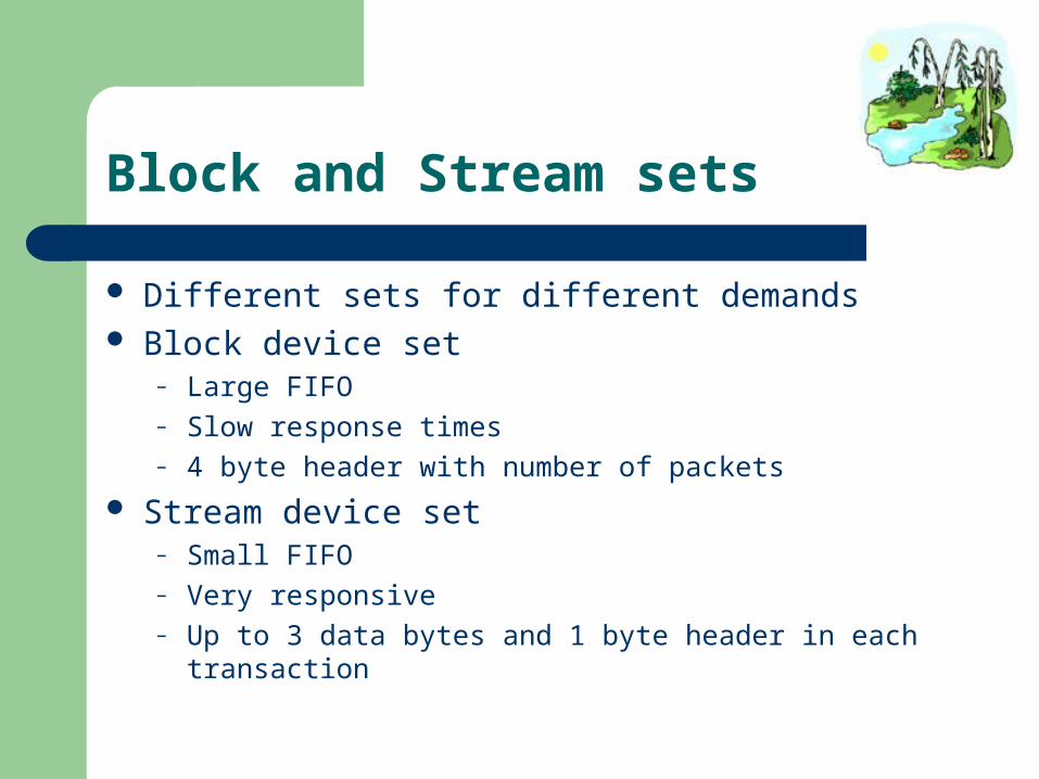
Block and Stream sets
Different sets for different demands Block device set
– Large FIFO– Slow response times– 4 byte header with number of packets
Stream device set– Small FIFO– Very responsive– Up to 3 data bytes and 1 byte header in each transaction

FIFO set driver
Implemented functions include:– Read– Write– Empty check
Different functions for different sides

Issues
Expected issues
Unexpected issues

No full / empty indication
Problem: The CPUs are unaware of the Sets’ status
Exceptions? Arbitration control - Wait? Retry? Retry ignored by PLB IPIF Retry for OPB, Wait for PLB
Prevents crashes in extreme cases

Empty Controllers
Does not help with Interrupts We must empty the set after any interrupt Must have an empty indicator
Empty ports from FIFO sets Accessed via IPIFs on different buses 32 FIFO sets can be connected to one empty
controller Asserted between packets

Different behavioral settings
Different set Different behavior Multiple cores are cumbersome Change setting via EDK

PCI & ALI support
Usage of PCI & ALI bridge– Initialization– Configuration
Serial Port Driver Two devices conflicts … Timing Problems with SW of MB Thanks to Igor and Leonid for keyboard code and
PCI & ALI support Very bad documentation of these issues by
and Xillinx

Serial Port Driver
Driver for both Serial ports– Initialization and configuration function
Can choose which of the two ports to initialize Settings configuration for the chosen port
– Byte Send/Receive/Check functions– String Send/Receive/FIFO-Check functions
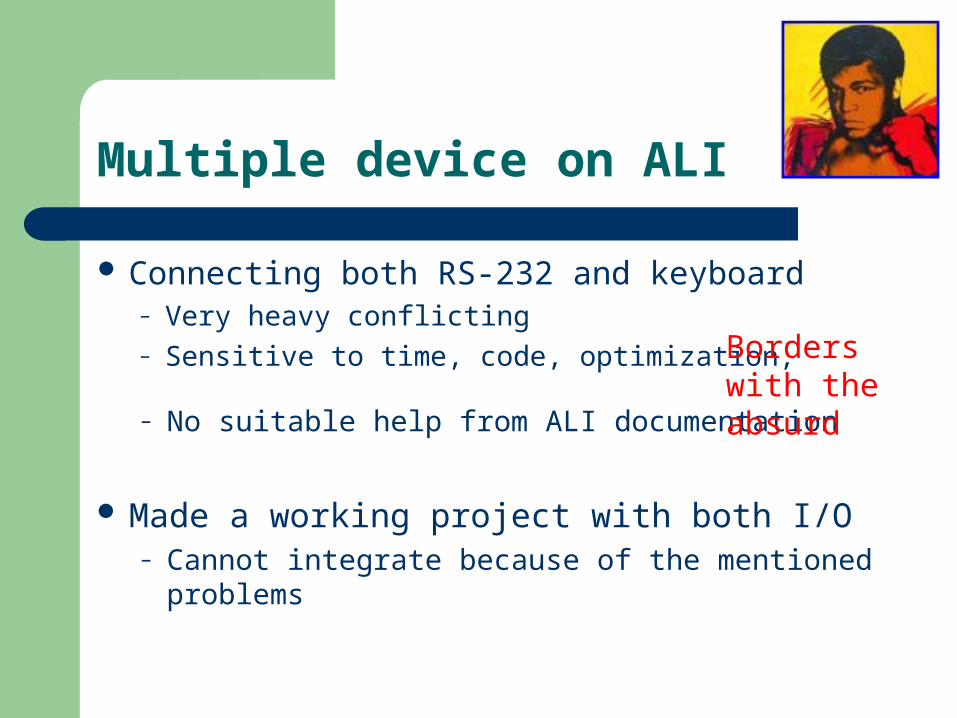
Multiple device on ALI
Connecting both RS-232 and keyboard– Very heavy conflicting– Sensitive to time, code, optimization,
– No suitable help from ALI documentation
Made a working project with both I/O– Cannot integrate because of the mentioned
problems
Borders with the absurd
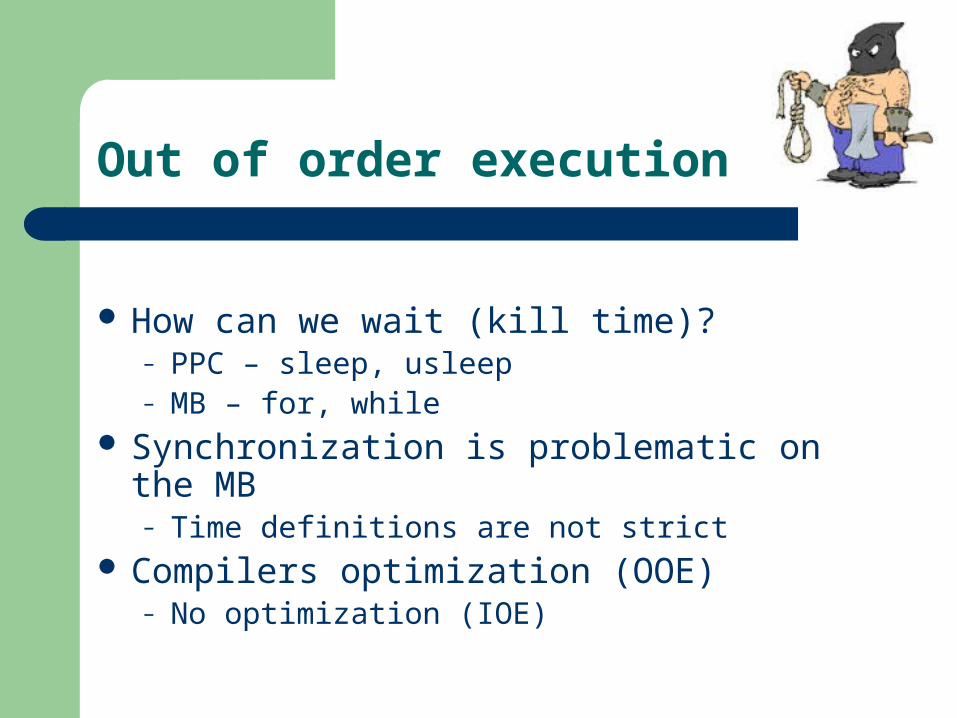
Out of order execution
How can we wait (kill time)?– PPC – sleep, usleep – MB – for, while
Synchronization is problematic on the MB– Time definitions are not strict
Compilers optimization (OOE)– No optimization (IOE)

64 bit transactions
PPC 32 bit Architecture PLB supports 64 bit data transactions PPC supports 32/64 bit PLB data interface 64bit transactions made through PPC cache
– Needs configuration and much work– A topic for a new project
is 64 bit Ready
Interrupts…
Indicate:– Sufficient data is awaiting– Data awaits sufficient time
Behavioral settings– Trigger – Charger– Not empty time out– Write stop time out

Current project status
PPC and MB system Two settings of buffers (8Kbit \ 256bit) Operation controllers, interrupts UART and virtual I/Os used

Demonstration
We transmit over 2 channels:– Block FIFO – file or keyboard– Stream FIFO – generated by counter
One reads from the UART (keyboard, file) Second, reads from a memory and writes
back
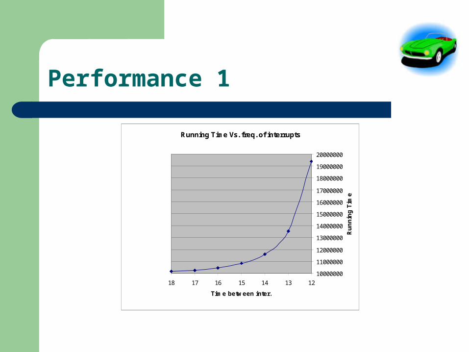
Performance 1
Running Time Vs. freq. of interrupts
10000000
11000000
12000000
13000000
14000000
15000000
16000000
17000000
18000000
19000000
20000000
12131415161718
Time between inter.
Ru
nn
ing
Tim
e

Performance 2
MB cannot handle with fast Interrupts The system stops responding before it
becomes useful. For slower interrupts, the time is constant MB is giving advantage in poling

Possible future improvements
Using the cache to perform 64bit transactions Better / more stable systems with PCI Timing / synchronizations with MB Arbitration issues Burst mode Exceptions

Note : the trademarks and registered trademarks of the products appearing in this presentation are hereby recognized as being the property of their respective owners.
Thank you for your attention!
Thanks