Wood Waste Recovery: Size Reduction Technology Studyinfohouse.p2ric.org/ref/13/12639.pdf · Wood...
72
Wood Waste Recovery: Size Reduction Technology Study NIST MEP Environmental Program
Transcript of Wood Waste Recovery: Size Reduction Technology Studyinfohouse.p2ric.org/ref/13/12639.pdf · Wood...

Wood Waste Recovery:
Size Reduction Technology Study
NIST MEP
Environmental Program

WOOD WASTE SIZE REDUCTION
TECHNOLOGY STUDY
FINAL REPORT
Prepared for
CWCA division of the Pacific NorthWest Economic Region (PNWER)
2200 Alaskan Way, Suite 460
Seattle, Washington 98121
December 1997
Prepared by
Re-Sourcing Associates, Inc.
CPM Consultants, Inc.
in partnership with
Boise Cascade Corporation
This recycled paper is recyclable
Copyright © 1997 CWC. All rights reserved. Federal copyright laws prohibit reproduction, in whole or in part, in any printed,mechanical, electronic, film or other distribution and storage media, without the written consent of the CWC. To write or call forpermission: CWC, Alaskan Way, Suite 460, Seattle, Washington 98121, (206) 443-7746.
DisclaimerCWC disclaims all warranties to this report, including mechanics, data contained within and all other aspects, whether expressed orimplied, without limitation on warranties or merchantability, fitness for a particular purpose, functionality, data integrity, or accuracyof results. This report was designed for a wide range of commercial, industrial and institutional facilities and a range of complexity andlevels of data input. Carefully review the results of this report prior to using them as the basis for decisions or investment.
Report No. CDL-97-3

TABLE OF CONTENTS
EXECUTIVE SUMMARY ...............................................................................................................1
1.0 SUPPLY OF SECONDARY WOOD FIBER ..........................................................................4
1.1 MILL RESIDUALS ............................................................................................................... 5
1.1.1 Clean Manufacturing Residuals ......................................................................................... 5
1.1.2 Remanufacturing Residuals ............................................................................................... 5
1.2 URBAN WOOD (MANUFACTURED AND CONSTRUCTION WOOD)......................... 6
1.2.1 Pallets and Crates ............................................................................................................ 6
1.2.2 Construction and Demolition Wood.................................................................................. 7
1.3 GREEN WOOD.................................................................................................................... 8
1.3.1 Forestry Residuals............................................................................................................ 8
1.3.2 Agricultural Wood.............................................................................................................8
1.3.3 Land Clearing Wood........................................................................................................ 8
2.0 WOOD WASTE PROCESSING SYSTEMS......................................................................... 9
2.1 HISTORICAL INFLUENCES ON WOOD WASTE PROCESSING SYSTEMS................ 9
2.1.1 Influence of the Solid Waste Industry.................................................................................9
2.1.2 Influence of the Forest Products Industry...........................................................................9
2.2 CURRENT WOOD WASTE PROCESSING SYSTEMS....................................................10
2.3 NEW DEVELOPMENTS.....................................................................................................12
3.0 VALUE-ADDED MARKETS FOR SECONDARY WOOD FIBER ..................................13
3.1 MARKET DYNAMICS .......................................................................................................13
3.2 THE IMPORTANCE OF SIZE REDUCTION TECHNOLOGIES ......................................15
3.3 REVIEW OF VALUE-ADDED APPLICATIONS...............................................................15
3.3.1 Pulp & Paper..................................................................................................................16
3.3.2 Reconstituted Panelboard................................................................................................17
3.3.3 Fiber and Composite Applications...................................................................................17
3.3.4 Mid-Value Applications ..................................................................................................18
3.3.5 Biomass Fuel Applications...............................................................................................18
4.0 SIZE REDUCTION EQUIPMENT ASSESSMENT............................................................19
4.1 PRIMARY SIZE REDUCTION............................................................................................19
4.2 SECONDARY SIZE REDUCTION.....................................................................................20

4.2.1 Re-Chipping ...................................................................................................................21
4.3 SIZE REDUCTION EQUIPMENT TYPES..........................................................................23
4.3.1 Chippers.........................................................................................................................23
4.3.2 Hogs...............................................................................................................................26
4.3.3 Hammermills ...................................................................................................................28
4.3.4 Shredders .......................................................................................................................29
4.3.5 Hybrid Size Reduction Equipment....................................................................................30
4.4 MATRIX OF EQUIPMENT TYPES ...................................................................................32
5.0 SCREENING EQUIPMENT ASSESSMENT......................................................................33
5.1 FLAT OSCILLATING (CIRCULAR MOTION).................................................................33
5.1.1 Free Suspended Screens .................................................................................................33
5.1.2 Controlled Throw Screens...............................................................................................34
5.2 SHAKER AND VIBRATORY SCREENS/CONVEYORS..................................................34
5.2.1 Screen Applications ........................................................................................................34
5.2.2 Vibratory Screening/Conveying .......................................................................................35
5.2.3 Vibratory Taper-Slot & De-Stoning Screens ...................................................................36
5.3 DISC SCALPING SCREENS..............................................................................................36
5.4 TROMMEL SCREENS........................................................................................................38
5.4.1 Dry Trommel Screens .....................................................................................................38
5.4.2 Wet Trommel Screens.....................................................................................................39
5.5 VAT TYPE WASHING SYSTEMS .....................................................................................39
5.6 HYBRID CLEANERS/CLASSIFIERS/DEBARKERS .........................................................40
5.7 AIR CLASSIFICATION/SEPARATION.............................................................................41
6.0 CHIP SAMPLING & PRODUCTION TESTS.....................................................................42
6.1 CHIP SAMPLING PROCEDURES .....................................................................................42
6.1.1 Sub-sample Collection....................................................................................................42
6.1.2 Compositing....................................................................................................................43
6.2 SAMPLE ASSESSMENT....................................................................................................43
6.3 TESTING OBJECTIVES......................................................................................................47
6.4 TEST # 1 - EVALUATION OF HOGGED FIBER SAMPLE..............................................48
6.4.1 Test Objectives...................................................................................................................48

6.4.2 Description .....................................................................................................................48
6.4.3 Findings ..........................................................................................................................49
6.5 TEST # 2 - EVALUATION OF CHIPPING EQUIPMENT.................................................50
6.5.1 Test Objectives...............................................................................................................50
6.5.2 Description .....................................................................................................................50
6.5.3 Findings ..........................................................................................................................50
6.6 TEST # 3 - EVALUATION OF HYBRID EQUIPMENT.....................................................51
6.6.1 Test Objectives...............................................................................................................51
6.6.2 Description .....................................................................................................................51
6.6.3 Findings ..........................................................................................................................51
6.7 TEST # 4-A EVALUATION OF RE-CHIPPING EQUIPMENT (SEPTEMBER 1996).......52
6.7.1 Test Objectives...............................................................................................................52
6.7.2 Description .....................................................................................................................52
6.7.3 Findings ..........................................................................................................................52
6.8 TEST # 4-B EVALUATION OF RE-CHIPPING EQUIPMENT (APRIL 1997)..................52
6.8.1 Test Objectives...............................................................................................................52
6.8.2 Description .....................................................................................................................53
6.8.3 Findings ..........................................................................................................................53
6.9 TEST #4-C EVALUATION OF RE-CHIPPING EQUIPMENT (JUNE 97: NICHOLSONROTODRUM RE-CHIPPER @ NICHOLSON - SYDNEY, BC) .............................................53
6.9.1 Test Objectives...............................................................................................................53
6.9.2 Description .....................................................................................................................54
6.9.3 Findings ..........................................................................................................................54
7.0 CONCLUSIONS AND RECOMMENDATIONS FOR SECONDARY WOOD FIBERRECOVERY............................................................................................................................55
7.1 TECHNICAL BARRIERS ....................................................................................................55
7.2 RECOMMENDATIONS TO OVERCOME TECHNICAL BARRIERS..........................56
7.2.1 Modified Tooling.............................................................................................................56
7.2.2 Chipper Feed System......................................................................................................57
7.2.3 Equipment Operation......................................................................................................58
7.3 FUTURE DIRECTIONS.......................................................................................................58

8.0 ACKNOWLEDGMENTS ......................................................................................................59
9.0 BIBLIOGRAPHY...................................................................................................................60

1
EXECUTIVE SUMMARY
The critical steps in processing wood waste for recovery are size reduction and contaminant removal.
This study is focused on engineered size reduction strategies that may allow processed wood waste to
penetrate feedstock markets for high value fiber products, and includes contextual references to
interdependent contaminant removal technologies. A broad range of alternatives for wood waste size
reduction are considered in this report, within the realm of processing to meet the requirements of
various end-use applications. Fiber market applications for recycled wood include the manufacturing of
various pulp and paper products as well as engineered wood panels and other products, discussed in
subsequent sections.
Size reduction technologies for processing recovered wood wastes for recycling use in fiber market
applications must be designed to produce fiber particles that meet specific manufacturing requirements.
In the forest products industry, most manufactured fiber applications, including both paper and wood,
are designed to begin with a “virgin” wood chip. A virgin wood chip is a wafer-like particle of wood
fiber which is produced through some type of whole-log chipping process. Size reduced chunks of
recovered wood waste are commonly referred to as chips, but often have very different characteristics.
Technologies conventionally applied to the size reduction of recovered wood wastes tend to sacrifice
cutting surface tolerances for durability of equipment. This has been necessary because recycled wood
typically contains embedded contamination in the form of metals or inorganic grit which must be freed
by grinding. One of the objectives of this study has been to consider current alternatives which may
allow processors to balance these attributes to achieve high quality reduction in an economically viable
manner. Chippers, hogs and hybrid reduction equipment are reviewed and contrasted within this study
as the principal reduction alternatives.
This study places an emphasis on identifying appropriate size reduction technologies for handling post-
consumer and post-commercial sources of wood waste. Examples of such wood waste sources of
include remanufacturing trim, pallets or crates, and wood recovered from construction and demolition
activities. These represent the wood waste types which are the most difficult to process such that they

2
approximate the attributes and quality of virgin chips, and represent a significant waste management
concern.
Accomplishments in the European markets, where industry has been working at the recovery of low
value wood wastes longer than domestic markets, because of a more acute timber scarcity, have
inspired research on this project. Certain German wood recycling facilities have been found to have
developed direct chipping of contaminated wood wastes using specially designed chippers with
modified tooling to produce recycled wood chips. While economic conditions in other parts of the
world may warrant more or less investment in recycling solutions than that which is viable under
domestic market conditions, the German example is one model which demonstrates the ability to
address processing needs through engineering.
In assessing the major categories and specific types of size reduction equipment currently available to
processors, it is clear that ongoing innovation in equipment design is occurring. Given a long-term
decline in the availability of timber resources, increased emphasis and allocation of capital toward
residuals recovery is being made by the forest products industry. Equipment manufacturers are
beginning to respond to the specific requirements of the wood waste recovery industry.
As explained by this study, many of the common waste streams of recoverable wood have significantly
different attributes from the whole log sources used in traditional chip production. Those differences
include the presence of foreign or non-wood contaminants, and often substantially lower moisture
content of recovered wood sources. The ramifications of such attributes and other considerations are
discussed in this study in order to provide criteria for the design and selection of size reduction
technologies.
During an industry expert focus group meeting held by the Recycling Technology Assistance Program of
the Clean Washington Center on December 9, 1996, fiber procurement managers pointed to quality
concerns as the principal reason for their limited consumption of recovered wood fiber. Chief among
quality concerns was the physical disparities of processed wood waste from the accustomed virgin
wood chips. Many in the industry now recognize that quality of recycled wood fiber is a function of the

3
type of reduction and level of ancillary processing applied. These experts generally agreed that market
opportunities for recovered wood fiber in high-value fiber products will continue to grow as long term
supply tightens, but placed emphasis on the need to diminish the gap in geometry attributes between
recovered and virgin wood chips, while maintaining a price discount relative to virgin chips.
The study concludes that chipping and hybrid reduction technologies offer the greatest potential for
processors to bring product closer in quality to that of virgin wood chips, thus developing a more stable
market position within the framework of market demand for chips from residuals. Several technical
barriers currently exist which have inhibited the use of such size reduction technologies in handling this
waste stream. Those include: unsuitable chipper cutter (knife type) and feeding methodology to control
the workpiece while it is being chipped.
This study discusses ways in which effective chipping, which requires that wood be cut across the grain
at a relatively shallow angle, might be achieved in processing the targeted urban wood wastes and other
wood residuals.
The authors of this study have several years of experience in the wood processing industry, and have
sought to consolidate information from industry experts, however, it is recognized that there are great
number of variations in size reduction applications, all of which may not be recognized by this study.
This project has been conducted in conjunction with other industry efforts to compile information about
wood waste processing. Information about size reduction technologies was provided to the Best
Practices in Wood Waste Recycling Project completed for the Clean Washington Center, in May 1997,
and preliminary findings of this study were presented at the subsequent Best Practices Workshops. The
Best Practices in Wood Waste Recycling Manual, produced by International Resources Unlimited for
the Clean Washington Center addresses reference information about size reduction and other wood
recycling.

4
1.0 SUPPLY OF SECONDARY WOOD FIBER
Waste wood is found in many places. This section provides a brief working context of the major supply
streams of recoverable wood wastes. It is important to understand the differences in wood waste types
and generation sources as they relate to size reduction. Each attribute of a given stream of recoverable
fiber has some influence on how it reacts in the size reduction process. Important attributes to be
considered include typical levels of contamination such as rock and grit, metals, and other foreign
materials; as well as moisture content, and physical dimensions of the unprocessed material.
One of the fundamental distinctions that can be made with regard to wood waste streams is between
“green” wood and “dry” wood. “Green” wood refers to fiber that has not been dried, while “dry”
wood refers to fiber that has been dried. Green wood typically has a moisture content by weight of 50
percent or more (wet basis), contrasted with dry wood which typically has a moisture content of 10 to
25 percent by weight (wet basis). Moisture content influences the way fiber fractures or cuts in the size
reduction process. The natural resiliency of green wood fiber can facilitate a smooth slicing action when
being chipped, but may inhibit fracturing when being hogged to produce a coarse and fibrous particle.
Dry wood fiber, conversely, will tend to shatter even under sharp reduction workpieces such as the
knives of a chipper, creating a different set of size reduction challenges.
Moisture content is only one of the distinctions between wood waste streams. Dry wood includes two
major categories: mill residuals and the broad “urban” wood waste stream. The chief distinction
between these two categories is the level of contamination. Mill residuals generally are defined as post-
industrial or post-commercial waste materials, while urban wood waste is typically defined as post-
consumer waste material. Post-consumer wood waste has been recovered after completing its intended
use.
Green wood has three sub-categories: forestry residuals, agricultural wood, and land clearing debris.
This category is more difficult to fit under a conventional definition of recycled material, but represents a
large waste stream that has historically been burned or left behind to rot. This type of material is not
altogether dissimilar from conventional whole log timber processed through debarking and chipping

5
equipment for pulp chips, but requires special handling and size reduction configurations to handle short
or irregular sizes.
1.1 MILL RESIDUALS
Mill residuals historically have been processed internally by waste wood generators to fuel biomass
combustion power sources. As discussed in the next section, due to its high quality, much of this stream
is increasingly being directed to value-added use in either the pulp and paper industry where it can be
re-chipped for use as pulp furnish, or to the panelboard sector for use in products such as
particleboard.
1.1.1 Clean Manufacturing Residuals
Clean manufacturing residuals are those materials generated by the primary manufacturing of wood
products, such as trim ends from dimensional lumber sawing. Typically, these residuals represent the
cleanest stream of waste wood in terms of the presence of foreign contaminants. While broadly
classified in this report as “dry” wood, this sub-category of mill residuals can include some green fiber
sources. As a general rule, a very high fraction of such residuals are recovered either for energy use or
fiber applications. Even bark residuals historically have been processed and marketed for landscaping
material.
1.1.2 Remanufacturing Residuals
Remanufacturing residuals are the materials that result from the assembly of cabinets, furniture, trusses,
or other mostly wood products. This stream is very similar to the clean manufacturing residuals
described above, but may also include some foreign materials such as plastic laminates or paints.
Even as the use of manufacturing and remanufacturing residuals as new product raw material continues
to grow, significant quantities continue to be used as biomass (hog) fuel.
According to the 1994 Washington State Directory of Biomass Combustion Facilities, prepared by the
Washington State Energy Office, more than 3.4 million bone dry tons of wood residuals were used as

6
biomass fuel in Washington State alone, during 1993. This number represents additional fiber supply
which may become available as increased tonnage is diverted for use as a raw material. Of the top ten
boilers in Washington consuming wood as hog fuel in 1993, nine were configured to use other fuel
sources as well, six of which included natural gas.
1.2 URBAN WOOD (MANUFACTURED AND CONSTRUCTION WOOD)
Urban wood fiber encompasses a broad range of wood types found throughout today’s economic
landscape . With the increased scarcity of timber resources, large timber beams and posts are
increasingly salvaged from demolition projects for reuse. Despite this practice, substantial quantities of
wood are discarded from both demolition and new construction projects. Salvage networks for pallets
and crates have developed in most urban hubs. In total, however, the infrastructure for recovery and
size reduction processing of urban wood waste is still largely undeveloped in most regions.
Urban wood is typically dry and often hardened from age, presenting a special challenge for controlled
size reduction. Moisture levels in recovered urban wood vary seasonally, depending on storage and
climate. End users in the Pacific Northwest report testing loads as low as 7 percent wet basis in the
summer and as high as 25 percent wet baiss in the winter, though those figures do not represent a
controlled test of the same fiber source.
1.2.1 Pallets and Crates
This category includes wood pallets, wood crates and packaging lumber. Nails or other metal fasteners
are common contaminants. This stream varies in species composition across the country, with a
majority comprised of hardwood species. Pallet recovery and repair is on the rise, but even these
businesses generate extensive wood residuals from broken and non-standard pallets.

7
1.2.2 Construction and Demolition Wood
Construction and demolition wood consists of mostly softwood species dimensional lumber and
engineered wood from construction and demolition activity, including the following categories:
New Dimensional Solid Lumber Scraps
New dimensional solid lumber scraps includes trim ends, off-spec materials, and other solid wood
residuals from framing and related construction activities. The material may include wood painted with
latex or oil based paints.
New Reconstituted or Otherwise Engineered Wood Products.
New reconstituted or otherwise engineered wood products may contain cured adhesives as the product
binder. This includes plywood, Oriented Strandboard (OSB), particleboard, Medium Density
Fiberboard (MDF), waferboard, and other fiberboard or products thereof. The material may also
include wood painted with latex or oil based paints.
Sorted Demolition Wood
Sorted demolition wood is wood generated by demolition or renovation activity, which has been
segregated. This material may include incidental amounts (usually under five percent per load) treated
wood waste or non-wood materials. It does not include lead-based painted or asbestos laden
materials.
High tipping fees at disposal sites and restrictions on open burning are driving building and demolition
contractors to seek less expensive options, such as recycling, for their debris and construction scrap.
Some regions have seen the development of new service vendors, such as on-site construction recycling
sub-contractors, which make wood recycling increasingly convenient and attractive to the construction
industry. Additionally, new front-end sorting and segregation practices and technologies are developing
to allow increased recovery of wood fiber from the mixed demolition waste stream.

8
1.3 GREEN WOOD
1.3.1 Forestry Residuals
Forestry residuals consist of short log sections, tops, small diameter trees and other material typically left
behind after a logging operation is completed. This includes not only the material left in the forest, but
also wood residuals piled at interim staging areas. Whether this is a source of “recycled” wood is
debatable, but this is clearly an area where large amounts of usable fiber are left behind and mechanisms
for increased recovery are beginning to develop. Accurate supply tonnage data is not available, but
information from industry sources indicates that the yield from traditional forestry clean-up practices has
been as little as a third of the total volume of cellulose fiber available after whole logs are harvested.
Management practices for increasing the recovery of forest residuals are now developing, and are
expected to be implemented over the next 10 to 20 years.
1.3.2 Agricultural Wood
Agricultural generators of wood residuals include orchard operators who routinely generate prunings
and whole fruit trees when making species transitions. This material has traditionally been burned or
buried on site. However, expanding environmental regulations such as Clean Air Act requirements are
making those practices less feasible. With these changes, orchard residuals represent a new secondary
wood supply available for mulch and other applications. The average rate of generation is estimated at
approximately 3 tons/acre/year, according to industry representatives in Washington State.
1.3.3 Land Clearing Wood
Land clearing wood consists of woody vegetation from land clearing activity, such as stumps, log
sections, and other woody vegetation containing less than ten percent soils or rock. This is the “L”
component of the CDL acronym used to refer to the construction and demolition (C&D) waste stream
in some parts of the country. Such debris is limited to those areas where forested lands are used for
new development, often near growing urban areas.

9
2.0 WOOD WASTE PROCESSING SYSTEMS
Waste wood represents a tremendous volume of fiber which has yet to be fully realized as a viable
secondary fiber source. Utilization of mill residuals has been increasing over the past several decades,
to the point where they are now used in many value-added products. Recovery of forestry residuals is
much less mature in its development, but remains a tremendous potential resource. Urban wood waste
represents a large frontier of discarded wood fiber that has only recently begun to be tapped as a
material source for industry.
2.1 HISTORICAL INFLUENCES ON WOOD WASTE PROCESSING SYSTEMS
There are two major influences that have guided much of the development of the wood recycling
industry: the solid waste handling sector and the forest products industry. Both sides approach wood
recycling with different objectives, but together form a diverse industry.
2.1.1 Influence of the Solid Waste Industry
The major objectives of solid waste handlers with regard to wood recycling are twofold: process wood
to divert material from the waste stream and to achieve high volume, low cost size reduction for
transportation efficiency. Indeed many companies ground C&D debris for years just to maximize the
efficiency of trucking waste to the landfill.
Much of the size reduction equipment used by the solid waste industry to handle wood was developed
to handle size reduction of a broad range of waste materials, not limited to wood for waste handling. By
dedicating grinding equipment to wood waste, and processing to meet end-use requirements (such as
hog fuel), the waste industry has successfully achieved their goal of finding a low-cost disposal
alternative.
2.1.2 Influence of the Forest Products Industry
Conversely, the forest products industry approaches wood waste recovery from an entirely different
perspective. While low-cost, high-volume size reduction is generally a shared objective, consideration

10
of wood waste recovery is a means to an end of developing diverse supply portfolios. Size reduction in
the industry generally is determined from very specific chip requirements. The result is a thorough
operating familiarity with a broad range of equipment types.
One of the major wood processors in
the Northwest is a family owned
business. At one time, the business
operated three whole log chipping
facilities. Today, two of those
facilities have been closed and
replaced by the company with two
urban wood waste recovery
operations. Such processors are able
to draw on a long history of size
reduction experience, while adapting
to an entirely different stream of raw materials.
2.2 CURRENT WOOD WASTE PROCESSING SYSTEMS
Wood waste processing consists primarily of sorting, size reduction, and then screening for contaminant
removal and sizing. The elements must all work together in order to form a successful wood processing
operation. The old adage “garbage in, garbage out,” generally holds true when describing size
reduction, so receiving practices and sorting are important pre-cursors to the size reduction process.
Innovative processing configurations employing size reduction equipment (usually hogs) in various ways
with ancillary feeding, screening, and cleaning equipment have allowed dramatic improvements in the
ability to remove contamination from wood waste. Contaminant removal continues to be key to the
successful high grading of low value wood wastes. However, the next step in approximating the
characteristics of virgin wood chips is narrowing the gap in chip consistency and quality.
Construction &Demolition
Debris Handlers
Chippers Hoggers
•• Swing Hammer Hogs Swing Hammer Hogs•• Mass Rotor Hogs Mass Rotor Hogs
•• Tub Grinders Tub Grinders•• Shredders Shredders
Size ReductionTechnologies
Wood Recycling Industry
•• Hybrid Technologies Hybrid Technologies
Forestry /Logging
Companies

11
The primary size reduction step (see Section 4) is generally designed to produce a distribution of
materials without excess “fines” or “overs” which fall outside the desired size distribution of the end
product. However, screening of material subsequent to the size reduction step is important in order to
assure product quality.
Oversized materials are typically re-directed through the primary reduction step or sent to a secondary
reduction step. Besides engineering the size reduction step to produce the desired size of particles, it
must also be designed to free embedded contaminants for removal (see Section 5).
In the Pacific Northwest, a
well capitalized wood waste
recycling industry has
developed. The largest and
most sophisticated processors
have begun to serve the pulp
and paper and reconstituted
panelboard markets with
secondary wood fiber, gaining
experience processing
secondary wood to tight
market specifications.
Two Northwest wood recyclers, in particular, operate sophisticated processing lines with extensive
contaminant removal capabilities. These facilities have the ability to meet tight fiber market
specifications for contamination. Processing activity goes well beyond size reduction to include manual
sorting, multi-stage magnetic separation, air classification, screening for contaminant removal, water
separation, and screening for accurate sizing.
Even with the sophisticated levels of processing applied at these facilities, processed secondary wood
fiber continues to exhibit a lack of uniform physical characteristics and as a result, is having difficulty
GenerationSector
CollectionSystem
Receiving /Sorting
Size Reduction
Screening
MagneticSeparation
Metal Recycle
ChipCleaning:
Screening,Separation
Market

12
successfully penetrating high value fiber markets. The lack of uniform physical characteristics is a direct
function of the size reduction process for recovered wood wastes. A focus group of industry experts on
the utilization of secondary wood fiber held by the Recycling Technology Assistance Program (ReTAP)
on December 9, 1996, reaffirmed that concerns over uniformity and consistency in secondary wood
fiber supply continue to be of significance.
2.3 NEW DEVELOPMENTS
While there are no “turn-key” systems currently available to process waste wood feedstocks to fiber
market specifications, equipment manufacturers are moving in that direction. Existing processors serving
fiber markets typically assemble systems using equipment from three or more vendors and experiment
with a wide range of screening technologies to reach desired output specifications. Such technologies
may include electro-magnetic separation, vibratory screens, trommels, air knives, air classifiers, water
separation, disc screens or manual picking lines. The industry is now driving the development of new
types of equipment. These technologies are discussed in greater detail in sections 4 and 5 of this report.
Hogs are slowly evolving toward the ability to provide a more consistent shape of “chip” with cleaner
edges. Chippers are concurrently evolving to where they can handle the divergent nature of wood
waste feedstocks with greater capacity, reliability, and flexibility. Wood waste processors can now
choose among a wide range of equipment types and sizes, including large stationary or smaller, mobile
size reduction equipment.
While equipment continues to improve, processing remains capital intensive. Obtaining attractive
financing and operating at a high percentage of capacity remain key to long-term economic viability.
Since end-users are increasing their processing requirements, costs must be carefully controlled to
maintain processor economics. In addition, wood waste transportation costs are high, and while
improving, new options need to be developed to expand the processing from a local to a regional basis.

13
3.0 VALUE-ADDED MARKETS FOR SECONDARY WOOD FIBER
Traditionally, raw wood has been abundant in many parts of the country, particularly in the Northwest,
and wood waste has not been considered valuable enough to process and recycle. Industrial wood
waste was recovered and burned in boilers as a low value hog fuel. Most construction, demolition and
land clearing debris was burned or buried on site, or hauled to a disposal site.
Today, many of the major mills still operate boilers that are powered by biomass combustion energy
from hog fuel made from mill residuals. However, high quality mill residuals and non-saw grade timber
often go to pulp chip applications, and more recently, to a growing number of engineered wood
applications.
These newer mill residual applications, combined with the decreasing supply of virgin timber available
for milling, have created a shortage of mill residuals. At the same time, demand for chips in engineered
wood products and pulp and paper applications continues to grow. As a result, the industry has seen
the value of chips increase markedly. The differential value of wood chips in production applications
versus combustion has caused mills to largely divert their mill residuals from hog fuel uses to higher value
uses.
3.1 MARKET DYNAMICS
Like many domestic natural resources, cyclical market conditions periodically boost the short-term
supply of virgin wood chips, however, the long-term trend is generally anticipated to reveal increased
scarcity. In the Northwest, curtailment of harvests on federally-owned forests since the late 1980s has
created a decrease in overall supply. As the demand for wood chips in this region has begun to exceed
conventional supply, end-users have begun to consider alternative fiber sources.
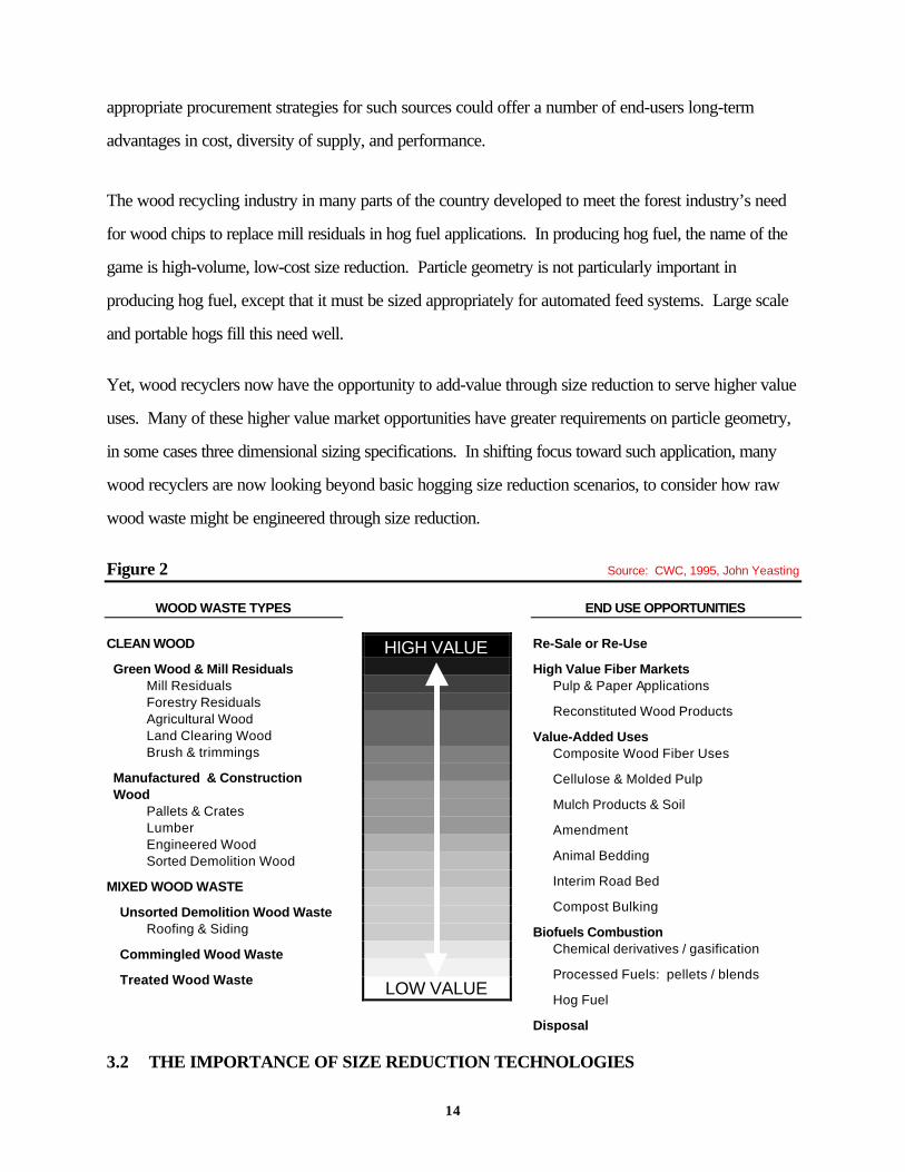
Many mills have begun taking sophisticated approaches toward utilizing wood chips from a variety of
secondary sources for high value uses and to meet hog fuel needs to power their boilers. Figure 2
illustrates relative values of both wood waste generation streams and end market uses. While low virgin
chip prices have currently depressed the use of recycled wood in fiber applications, the development of
14
appropriate procurement strategies for such sources could offer a number of end-users long-term
advantages in cost, diversity of supply, and performance.
The wood recycling industry in many parts of the country developed to meet the forest industry’s need
for wood chips to replace mill residuals in hog fuel applications. In producing hog fuel, the name of the
game is high-volume, low-cost size reduction. Particle geometry is not particularly important in
producing hog fuel, except that it must be sized appropriately for automated feed systems. Large scale
and portable hogs fill this need well.
Yet, wood recyclers now have the opportunity to add-value through size reduction to serve higher value
uses. Many of these higher value market opportunities have greater requirements on particle geometry,
in some cases three dimensional sizing specifications. In shifting focus toward such application, many
wood recyclers are now looking beyond basic hogging size reduction scenarios, to consider how raw
wood waste might be engineered through size reduction.
Figure 2 Source: CWC, 1995, John Yeasting
WOOD WASTE TYPES
CLEAN WOOD
Green Wood & Mill ResidualsMill ResidualsForestry ResidualsAgricultural WoodLand Clearing WoodBrush & trimmings
Manufactured & Construction Wood
Pallets & CratesLumberEngineered WoodSorted Demolition Wood
MIXED WOOD WASTE
Unsorted Demolition Wood WasteRoofing & Siding
Commingled Wood Waste
Treated Wood Waste
HIGH VALUE
LOW VALUE
END USE OPPORTUNITIES
Re-Sale or Re-Use
High Value Fiber MarketsPulp & Paper Applications
Reconstituted Wood Products
Value-Added UsesComposite Wood Fiber Uses
Cellulose & Molded Pulp
Mulch Products & Soil
Amendment
Animal Bedding
Interim Road Bed
Compost Bulking
Biofuels CombustionChemical derivatives / gasification
Processed Fuels: pellets / blends
Hog Fuel
Disposal
3.2 THE IMPORTANCE OF SIZE REDUCTION TECHNOLOGIES

15
During an industry expert focus group meeting held by the Recycling Technology Assistance Partnership
of the Clean Washington Center on December 9, 1996, fiber procurement managers pointed to quality
concerns as the principal reason for their limited consumption of recovered wood fiber. Chief among
quality concerns was the physical disparities of processed wood waste from virgin wood chips. Many
in the industry now recognize that quality of recycled wood fiber is a function of the type of reduction
and level of ancillary processing applied.
Industry experts explain that the globalization of virgin wood chip markets and cyclical pricing patterns
influence short-term chip procurement decisions. However, given the long-term pressures on the supply
of virgin fiber, the general consensus of industry experts was that market opportunities for recovered
wood fiber in high-value fiber products will continue to grow. Emphasis, however, was placed on the
need to diminish the gap in geometry attributes between recovered and virgin wood chips. At the same
time, the costs of size reduction and ancillary processing must be controlled to give recovered wood
chips a price advantage over virgin chips, necessary to justify procurement.
3.3 REVIEW OF VALUE-ADDED APPLICATIONS
Applications for fiber from secondary wood sources continue to grow. For example, the ability of the
industry to fiberize wood for uses such as new composite products, cellulose insulation and molded pulp
is improving. To better understand the specific quality requirements of wood chips as they relate to
sizing for these new applications, as well as existing higher value applications, mill representatives were
informally interviewed during this study. The geometry of recovered wood chips has ramifications that
are specific to many of the fiber manufacturing applications, as well as those which are common among
several applications.

16
3.3.1 Pulp & Paper
There are several technologies that can be employed in the production of wood pulp for use in paper
manufacturing. Two major processes represented by industry representatives contacted are: Thermo-
Mechanical Pulping (TMP) and Chemical Thermo-Mechanical Pulping (CTMP). CTMP, also known
as semi-chem digesting, is a newer and more prevalent process today. It employs chemicals that aid in
the breakdown, or fiberization, of the wood chips. Each of these processes employ large refiner plates,
where the fiber is compressed between large counter rotating discs operating at very close tolerances.
These refiners have a very low tolerance to any non-wood materials that may cause damage to the
plates, requiring that recyclers provide very clean material.
The size of chips entering the pulping process has several ramifications. The length and orientation of
cut largely determine the length of fibers in the finished pulp. The thickness, width and coarseness of the
chip determine resident time or length of the pulping process. The width and coarseness also influence
how well the chips perform in large automated storage, conveying and feeding mechanisms. Overly
coarse chips, such as the typical hogged fiber chunk, are subject to bridging (fibers adhering to each
other), which can cause costly clogging of such systems.
Beyond the importance of chip uniformity for proper feeding, most mill representatives explain that the
pulping process can accommodate a range of chip sizes. However, it is important that there is a level of
consistency in the chip characteristics, so that pulping reactions can be predicted with confidence.
Semi-chem digesters have a greater ability to handle coarse fiber particles since the greater surface area
allows rapid chemical and moisture penetration, but still require consistency in size.
Many of the pulp users that have successfully utilized chips from recovered wood fiber have revised
sizing requirements for processors downward, to effectively minimize the variation between individual
particles. This is balanced with sacrificing fiber length. Most pulp producers today utilize significant
quantities of post-consumer paper fiber in some grades of pulp. Secondary wood fiber may serve as a
source of post-consumer fiber offering longer and stronger fibers than those of shorter waste paper
fibers.

17
3.3.2 Reconstituted Panelboard
Reconstituted panelboard is a broad category of engineered composite wood products that includes
particleboard, MDF, OSB, plywood, hardboard, and several others. Representatives of this industry
explain that fiber geometry can be one of the greatest limiting factors in their consideration of chips from
recovered wood fiber, depending on the application.
Currently, the only panelboard producers able to utilize secondary wood fiber in manufacturing are
those producing particleboard, MDF, or hardboard. These products employ finely sized fiber particles
as a manufacturing input, and have a recent tradition of utilizing mill residuals as the source of this fiber.
Such residuals, along with other lower value wood waste sources can be processed through either
hogging or chipping equipment, along with subsequent secondary reduction steps such as flaking or
fiberization to approximate the characteristics or feedstocks from virgin fiber sources.
Other applications, such as OSB and oriented strand lumber (OSL), rely more heavily on tight chip
sizing requirements to achieve the engineered attributes of the finished product. In the case of OSB and
OSL, clean-edge, wafer-like chips of specified lengths are required. Since chips of such geometry
cannot currently be produced from waste wood, these applications use only virgin wood chips from
whole-log sources. This market generally pays less for feedstock material than pulp and paper
producers because of slightly less stringent requirements on species type and other attributes.
3.3.3 Fiber and Composite Applications
Cellulose insulation and molded pulp products are emerging markets for recovered wood. These uses
employ a fiberization process. Additionally, several new composite wood products are on the horizon
which may offer potential for utilization of recovered wood, including cement-fiber, thermoplastic-fiber
and others. The specification for wood fiber in such uses will be dependent on the characteristics of the
desired product. Due to secondary size reduction steps required for most of these applications, they
will typically have the same low tolerance to metals, dirt, rock or sand as pulp applications, but may
offer broader tolerances for trace amounts of materials such as plastics, laminates or fiberglass which
are not acceptable in pulp processes.
18
According to one major project considering recovered wood fiber in a plastic-wood composite
application, chip geometry is also important. The process involves flaking as a final size reduction step.
Flaking takes the fiber particles down to roughly .015 inches thickness with a desired length of 1 inch.
If poor quality (overly coarse or highly fractured) chips are fed to this process, an excessive amount of
fines or sawdust size material will be produced, adding significantly to material costs.
3.3.4 Mid-Value Applications
In addition to the high and low value applications for recycled wood waste, a number of mid-value
applications exist. Among these are: animal bedding, interim road beds, mulch and soil amendments,
bulking agents for compost production, chemical derivatives, and processed fuel pellets or blends. Each
of these end uses may have value in particular situations. For instance, interim road bed applications
may make sense for the utilization of rural land clearing wood debris or forestry residuals. Most of
these applications have relatively limited requirements on chip geometry, with the exception of animal
bedding, which is desired to have clean, smooth edges.
3.3.5 Biomass Fuel Applications
Biomass combustion of wood for energy, also known as hog fuel, has been a common use of secondary
wood due to a historical abundance of wood residuals. Industrial conversion to lower cost fuels such as
natural gas and the increased stringency of air quality control requirements have significantly eroded long
term demand for hog fuel in the Northwest. As this market declines, Washington processors serving
this market will have to find other markets, such as compost, for low grade waste wood chips. The
alternative for processors is to make the necessary capital investment to bring chips up to the
specifications for higher value markets.
4.0 SIZE REDUCTION EQUIPMENT ASSESSMENT
Size reduction equipment is perhaps the most important element of wood waste processing systems as
defined in Section 2. Size reduction equipment determines the size and shape of the wood particles that
are produced. The types of size reduction used depend on the end-use markets being served. Most

19
wood recovery operations use primary size reduction and cleaning, and many add secondary size
reduction and additional cleaning stages. Some wood recovery operations are now using hybrid size
reduction technology instead of, or in combination with, primary or secondary size reduction.
Re-chipping technologies may be employed as a secondary size reduction stage in recycled wood
processing. This technology may provide the ability to take recycled wood fiber which has been
processed through primary reduction and screened for contamination, to a state of greater uniformity in
sizing. Alternatively, a simplified process may be developed which directly chips contaminated wood
waste.
The types of equipment discussed in this section typically employ either very sharp tooling (knives) to
slice the wood fiber (chippers) or more blunt tooling which reduces the wood particles through impact
force (hogs, shredders, hammermills), or a combination of the tooling (hybrid equipment). Each type of
size reduction equipment has variations in how material is fed through the equipment, speed of
operation, and several other design characteristics.
4.1 PRIMARY SIZE REDUCTION
The primary size reduction philosophy to date has been to select primary processing machinery that fits
with the quantity, quality, and range of materials that are to be processed. This philosophy is still sound.
However, processing techniques and developing technologies must be utilized to allow recyclers to
better customize wood waste products to best serve the variety of end markets , with the additional
objective of optimizing the market value of the products.
Current practices for primary reduction of C&D wood materials employ the use of large hogs; generally
swing hammer, fixed hammer, and mass-rotor types. Typically, primary reduction equipment and set-
up is selected so that it will maximize the amount of processed materials in the desired size range, while
minimizing fines and overs. This is often difficult due to the extreme variation in raw materials
processed. Seasoned recyclers have experimented with the type of hog, and the size of bottom grate
employed, that will provide the highest percentage of accepts in the desired size range. The target size

20
range for primary reduction in the industry is generally < 3", with some restrictions to the amount of
"fines" depending on the end user. Hogs and other reduction equipment which employ more blunt
tooling have characteristically greater durability for handling feedstocks with contamination. However,
this type of equipment produces wood particles which are less uniform and less consistent than actual
“chip” specifications allow. These particles have very coarse geometry.
Newer equipment that has design characteristics of both types of equipment, known as hybrid size
reduction equipment, employs semi-sharp cutting surfaces with high durability to produce particles
which are more uniform in nature and capable of handling today’s broader range of feedstocks. Hybrid
equipment is increasingly being used in place of traditional primary size reduction equipment.
In general, reduction equipment such as chippers, which employ sharp tooling, have a greater sensitivity
to contaminants which dull the cutting surface and reduce efficiency. For this reason, chippers are
generally not used as primary size reduction equipment for recycled wood waste.
4.2 SECONDARY SIZE REDUCTION
In-line secondary reduction (or provisions to recycle “overs” to the primary hog) is often essential to
ensure compliance with product specification and to maximize wood fiber recovery.
Following primary reduction, tramp metal removal equipment is usually employed to remove "free"
tramp metals (metal that has been separated from the parent wood piece in the primary reduction
process). These magnets (depending on the type and strength) may also remove some wood where
metal remains lodged in the wood piece, however, this will generally be a very small percentage of the
total material processed.
Following first stage metal removal, the processed material is generally screened by variety of screen
types (refer to section 5 for description of screen types). The primary screening process will remove
the fines as well as separate the overs, as defined by the targeted product application. It is these overs
that are then directed back to the primary hog for final reduction. The product from this secondary

21
process will again require de-metalling and screening before joining the accepts flow from the primary
screen(s).
4.2.1 Re-Chipping
Re-chipping has been part of the forestry based industry almost since the inception of primary chipping,
at least for the past 50 years. As the demand for chips started to grow along with the growth of
chemical based pulping, it quickly became apparent that chip quality and consistency were major
factors, not only in final pulp quality, but in overall fiber recovery (ratio of finished pulp tonnage to raw
fiber into the process).
Research has been completed over the years by research groups, suppliers, and end users on chipping
theory, and equipment control parameters (angle of cut, knife angles and clearances, etc.). Refinements
based on the research have focused on trying to optimize chipping technology to produce the preferred
chip. The preferred chip, initially for chemical pulping, and later for mechanical refining, consists of a
chip with smooth cut ends, clean shear surfaces, and within a very tight thickness tolerance range of
4mm to 7mm (TAPPI Journal “Chip Thickness Control with a Conventional Screening System,” pp.
293-296, Sept. 1991).
It was quickly found that a number of variables, both equipment related as well as raw material related,
can have a significant impact on the so called "perfect" chip. Even under the best of conditions and
chipper set-up, a fairly wide range of chip sizes are produced, from very fine material to large slivers
(overs). Primary chip producers, whether an integral part of the primary process, or chipping plants
producing on contract, screen the chips to remove the unwanted fines (generally less than 3/16") and
also for the overs (generally greater than 2").
The re-chipper was developed in order to capture this > 2" fraction (along with the ability to process
small broken log chunks/slivers or "fishtails" recovered from the sawdust waste conveyors). It was
quickly found that chipping small chunks of wood was not only challenging, but the results were

22
generally very poor. Despite the poor performance, many of the re-chipper configurations that were
developed are still in use in one form or another.
Three principal types of re-chippers have been developed: the straight drum-type, "V"-drum type, and
conventional disc. These machines, all of which use knives to chip virgin wood, utilize various numbers
of knives and angles, and different feed geometries, to try and align and hold the small chunks of wood
as they enter the knife cutting zone.
V-drum chippers, used for a number of years, have fallen out of favor due to their longer set-up time
and higher maintenance costs (more susceptible to tramp metal damage than the disc or straight drum
chipper). The trend for a number of years was toward disc chippers with a secondary spout above the
primary spout, designed specifically to handle overs. This configuration is usually used with closed loop
chipping, screening, re-chipping systems, where the chips are pneumatically conveyed to the screen
overhead and the overs fall directly back into the small overs chute. The disadvantage is that the chips
have to be re-screened, a costly and time consuming step.
The trend today is more to the straight drum chipper since it provides the capacity for a wider range of
feedstock sizes, and can handle broken ends and trim falldown along with a substantial flow of overs.
The key here is that a bottom screen is used, which with appropriate experimentation and selection of
opening size, can ensure a high level of acceptable chips on a one-pass-through.
Wood recyclers to date generally have not employed chipper technology in their operations for the
purpose of primary reduction of CDL materials. More recently, however, recyclers are becoming
increasingly aware of final product value ranges, which provides significant premiums for well formed
and clean chips. Many recyclers have implemented sort tables and conveyors where clean materials are
diverted (hand picked) to a separate line(s), allowing separate processing of this portion. The downside
here is the significantly higher processing costs (primarily labor) allocated to a very small percentage of
the overall material processed. This generally has not been found to be economical.

23
The challenge for the industry is to develop systems and equipment that enable a large component of the
CDL waste stream to be chipped at the primary stage rather than ground by conventional hogs. This is
particularly true if the desired product is chips that approximate the size, geometry, and value of typical
virgin wood pulp chips.
4.3 SIZE REDUCTION EQUIPMENT TYPES
There are three very basic types of size reduction equipment which are used to process wood residuals,
and many new types emerging which include multiple characteristics. These are chippers, hogs,
hammermills and shredders.
4.3.1 Chippers
Chippers have a long history of use with clean traditional feedstocks such as whole logs and mill
residuals. This type of equipment produces wood particles which we know as “chips” with two
surfaces and clean edges of specified dimensions.
Disc Type Chippers. Disc type chippers have been used for many decades for primary reduction of
logs to quality chips for the production of pulp and paper products. These chippers range in size from
the whole log chippers of 140" to 150" in diameter with 2500 hp direct coupled synchronous motors, to
the 48" size, belt driven with 150 to 200 hp induction motors for chipping waste wood in the sawmill
(trim ends, off-cuts and edgings for the production of residual chips).
Disc chippers have been refined to some degree over the years, however, the basic principle of cutting
chips of varying fiber length (depending on the end use) at an angle diagonally to the grain, has not
changed significantly. Tooling has become more sophisticated with various "throw-away" knife systems,
along with refinement of machine set-up and materials to reduce the maintenance costs in operating this
type of equipment.
Disc type chippers are supplied in two basic configurations, 1) Horizontal feed, and 2) Gravity or drop
spout feed.

24
Horizontal Feed Disc Chippers. Horizontal feed chippers are generally employed where the material
to be chipped is longer than 8 feet, particularly tree length chipping operations. However, there are
hundreds of smaller horizontal feed waste wood chippers operating in sawmill plants which handle all
lengths from short blocks to full length
edgings up to 20 feet long. This is a
matter of economics, and is a relatively
efficient way of handling this type of
clean mill residual material, unless it is
chipped directly as part of the primary
sawing and integral chipping process.
Although this type of chipper is in
extensive use, one of the drawbacks,
due to the mix of size and shapes of
the material going into it, is the variable geometry of the chips produced, and the amount of fines losses.
There is substantial motion of the feed materials in the throat of this type of chipper, leading to
inconsistent sizing of the resulting chip, versus a comparable chip from a single solid piece being chipped
(in the same type of chipper).
To try and better control this action at the chipper knife face, several chipper manufacturers have
produced machines where the chipper disc is canted over on an angle towards the infeed conveyor.
This configuration has a tendency to "hold" the wood chunks better against the disc face because of the
compound chipping angle. The wood not only approaches the disc at an angle in the horizontal plane,
but is also cut on an angle in the vertical plane by the cant angle of the disc (this angle can be as much as
15 to 20 degrees). This action is intended to approximate the action from a drop spout chipper for
short wood.
Drop Spout Disc Chipper Basic design of this chipper is the same as the horizontal feed chipper,
except that the disc is fitted with a spout which approaches the disc at an angle of about 38 to 42
degrees (vertical plane). The disc is also maintained at a fairly standard angle in the horizontal plane,
Disc Chipper Profile
Angled Infeedchute
ObliqueShearingCuttingKnife

25
which provides a compound cutting angle on the wood being chipped. The chip is cut diagonally across
the grain in the flat direction (width of the chip) and again diagonally across the grain in the thickness
direction.
Drop spout chippers have been extensively used, to chip short pulp wood (8'), in the pulp and paper
industry on a world wide basis for many decades because of the high chip quality and reduced fines
produced with this configuration.
Chip discharge from the chipper housing can be by direct gravity discharge to a collector conveyor
under the chipper; directly behind the chipper through the back of the chipper housing; or pneumatically
discharged from the top of the chipper by fitting the disc with fan blades to provide pneumatic
conveyance. This latter method has been widely used due to the convenience, smaller foot print and
lower capital cost, however, not without some sacrifice in delivered chip quality in the form of additional
fines.
Drum Type Chippers . Drum type chippers are far less prevalent than the disc, however, have been
seeing increased use in processing waste virgin or residual wood in the last 20 years. The main reason
for their increased use is that the size of the finished product, specifically the amount of oversized chips
(or chunks) can be controlled by employing a basket screen on the bottom of the drum chipper. For
the primary processor, this can eliminate the need to screen the chips before shipment to the end user.
Generally all disc chipper-produced chips must be screened to remove slivers (or overs) before being
acceptable to the end user. A drum chipper can generally produce a more consistent chip while dealing
with a wide range of feed stock.
Another advantage of the drum chipper is its ability to process a wider size range of raw material. A
disc chipper capable of handling the same larger block size range would not be economically viable, and
would not be a wise choice, given the geometry of short waste material.

26
Drum chippers can also be supplied
in horizontal feed with a multiple
feed roll system, or alternatively a
gravity feed system. However, the
gravity feed system on the drum
chipper is generally perpendicular to
the drum shaft axis. There is no
advantage to skewing the infeed, in
the horizontal plane, on a drum type
chipper because of the way the
material is delivered to the knife
cutting circle (very randomly because of the shortness and randomness of the wood chunks).
4.3.2 Hogs
As a general note, "hogs" have been synonymous with the wood processing industry for many years,
and relates to their ability to take a wide range of raw material, under very wide surge conditions and
convert it into a product suitable for fuel to fire a power boiler (to a < 3" specification).
Swing Hammer. This type of hog has been used and has been preferred in the forest products industry
for many years because of the robust design, its ability to tolerate fairly large contaminants (both metal
and mineral), its ease of maintenance and minimum field set-up time for maintenance personnel.
These types of hogs can and do operate for extended periods of time with little maintenance attention,
other than necessary lubrication requirements. In many cases it is only after the machine fails to meet the
production demands and/or the quality of hog fuel falls below the minimum requirement that the machine
is shut down for service.
Fixed Hammer. The fixed hammer hog is a fairly recent aberration from the swing hammer machines,
and has been an attempt by some manufacturers (some fairly new in the field) to get higher energy into
Drum Chipper Profile
Cutting Knife
In Feed
Screen

27
the workpiece. The result, in effect, models the performance of the mass rotor hog, discussed below.
Use of this type of hog is very application specific, and is generally not used where a high percentage of
large mineral contaminants are expected. A typical application is for the reduction of reject large cross
section engineered wood product materials for recycling into the process or for fuel purposes.
Fixed hammer hogs usually have either replaceable hammer face inserts, or the ability to have the whole
hammer replaced when worn out.
Punch & Die. Punch and die hogs are as the name implies; the rotor is fitted with close tolerance fixed
cutters, while the anvil, in the work zone, is fitted with a die pattern that matches the fixed cutters. This
type of hog is very effective and efficient, however is very sensitive to mineral contaminants. It also has
a much longer set-up time and maintenance costs than a comparable-sized swing hammer hog. As
such, this type of hog is no longer used as the primary hog in large wood processing facilities.
Mass Rotor. The mass rotor hog is fairly new, was develop in the last 10 years, and now is finding
wide use as the primary reduction hog in many operations. The mass rotor hog is as the name implies;
the rotor is made up of a very heavy shaft, to which is fitted flame cut and machined solid steel plates
(plate up to 12" thick). The plates are cut so as to provide a machined surface for mounting replaceable
wear bars.
There are now approximately a dozen manufacturers of this type of hog (half a dozen major
manufacturers), each stressing the uniqueness of their specific design. These hogs are also available in a
full range of capacities from a few tons to over 150 tons per hour (TPH).
Knife Hogs. Knife hogs are also as the name implies, and employ knives for the reduction action
rather than impact per the previous types. Knife hogs are not in wide use today, however, were used in
specialized applications, such as the hogging of western red cedar bark, and some eucalyptus species in
Australia. This type of hog, if used in a highly contaminated application, often results in prohibitively
expensive operation and maintenance costs.
4.3.3 Hammermills

28
In the wood processing industry, hammermills are generally used in association with secondary
manufacturing, or as a secondary process in a primary manufacturing process. An example would be
the hammermilling of screened dry fines
in a panelboard plant for use as fuel for
a wood dust burner to fire the drying
system.
Although hammermills are available in
some very large sizes, they are
generally employed in size reduction
processes where there are no
significant contaminants, and where the
size of the finished product is fairly small. Final size is controlled by the use of screens on the bottom of
the machine. This type of equipment also generally requires pneumatic scavenging to provide air flow
through the machine as well as ensure efficient throughput capacity.
Grinders or Pulverizers are sometimes used interchangeably with hammermill nomenclature, and is highly
dependent on the type of industry (and history) in which the equipment has been employed.
Hammermills are generally run at rotor speeds two to three times faster than typical hog applications (up
to 3600 rpm). Hogs in the wood processing industry generally have a 1200 rpm limit, with many of the
larger units running in the 700 to 900 rpm range.
4.3.4 Shredders
Shredders are another class of reduction machine and the name covers a very wide range and type of
machine.
Low Speed High Torque. This type of machine has been available for the last 15 to 20 years,
however, it has only been in the last 10 years that it is finding wider use. This increase has been mostly
Impact Hammer Mill ProfileImpact Hammer Mill Profile
Heavy DutyHeavy DutyGridGrid
HammerHammer

29
attributable to environmental issues; landfill tipping fees, and restrictions on the types of materials that
may be landfilled. One of the major applications for shredders is that of tire shredding.
Low speed high-torque shredders can also be used for the reduction of waste or residual wood. They
are limited severely, however, in throughput capacity (relative to a large hammer or mass rotor type
hog) because of the slow rotor
speeds. Typically these machines
have two rotors as illustrated at
right, with rotor speeds < 20 rpm.
Because of the design and accuracy
of the intermeshing discs, these
machines have the capability of
applying very high shear loads to the
material being reduced. The pull-
through tip forces of this type of shredder can reach up to 200,000 lbs. with the use of dual hydraulic
systems, allowing reduction of a wide range of metal and synthetic products (recycled carpets for
example).
Infeed
Accepts
High TorqueCounter-RotatingDiscs
Shear Shredder

30
High Speed Shredders. There are a wide variety of machines in operation that have been tagged with
the shredder name, however, most of these machine can fit into the "Hammermill" category, either in the
vertical or horizontal configuration. Again the name given to any particular type of reduction machine is
highly dependent on industry experience, the function required of the machine, and the product
produced.
4.3.5 Hybrid Size Reduction Equipment
Hybrid size reduction equipment refers to equipment which seeks to combine the durability of hogging
equipment with the high-quality cutting action of chipping equipment. Principally, these types of
equipment seek to employ workpiece cutting surfaces which are sharper than those of a hog, but
capable of withstanding the wear experienced in high volume processing. The reduction action of this
equipment is not designed to slice wood like a chipper, but rather to use a combination of impact force
and cutting action to produce wood chunks with cleaner edges than the typical coarse shredded
geometry. New equipment designs and modifications to conventional equipment continue to emerge
and are being driven by the needs of a diverse wood waste processing industry.
In processing various forms of wood wastes and residuals, operational efficiency must be balanced with
desired quality output. Due to wear caused by the contaminants present in typical wood waste streams,
the use of chipping equipment as used to produce chips from logs and clean residuals is seldom feasible
with lower grade wood wastes. As a result, hogging equipment, which is more resistant to such wear,
must be used in the majority of wood waste processing applications. This equipment achieves cost
effective size reduction, but produces coarse wood particles rather than true chips. As the industry
seeks to move these lower grade wood waste materials to product applications requiring specific chip
characteristics, there is a need for equipment which can combine precision tooling without sacrificing
durability required to resist wear.

31
Rotary Knife Hog Designs.
Rotary knife hogs employ a design similar to that of a swing-hammer hog, only with “knives” mounted
on the rotor rather than hammers. These knives are not as sharp as those found in a chipper design, but
achieve a cleaner cutting action than that of a hog. The knives cut materials against an anvil or breaker
bar and force material out through heavy steel grates. These machines can tolerate a broader spectrum
of contaminants than chippers, but generally require relatively clean feed materials, as excessively
contaminated feedstocks can result in prohibitively expensive operation and maintenance costs.
Pan and Disc Design
Another hybrid size reduction design, called
“pan & disc” has been developed by a
Washington manufacturer, Universal Refiner
Corp. of Montesano, WA. This machine
employs a cutting disc fitted with sharp cutting
teeth, rather than conventional hammers.
According to product literature, one of the
design criteria was to address safety concerns
associated with rotary hog mechanisms used
in the common tub grinders.
The Universal Refiner design, found in their “Contender” model grinders, is a mobile unit, similar in size
to large tub grinders, but is hopper fed with the cutting action occurring deep within the machine.
Discharge grates on the perimeter of the bottom pan control particle size and allow hard contaminants to
pass through without being forced against the cutting disc. The machines employ a rotor speed lower
than conventional hogs, geared for high torque.

32
4.4 MATRIX OF EQUIPMENT TYPES
Equip. Type / Mfrs Reduction workpieceSpeed (RPM) Typical Feedstock
Sensitivity to Contaminants
Geometry of Particle Produced
ChippersDisc Chippers replaceable knives High high clean edge, two-
sided
Slant disc / horiz. feed whole logs
Drop spout / gravity feed clean residuals
Drum Chippers replaceable knives High high clean edge, two-sided
Horizontal feed whole logs
Drop feed / gravity feed clean residuals
HogsSwing Hammer swinging hammers Mod urban wood waste,
stumps/LC debrislow coarse, multi-
surface
Fixed Hammer fixed hammers Mod urban wood waste, stumps/LC debris
low coarse, multi-surface
Punch & Die fixed impact surfaces Mod urban wood waste, stumps/LC debris
moderate coarse, multi-surface
Mass Rotor rotating impact surface Mod urban wood waste, stumps/LC debris
low coarse, multi-surface
ShreddersLow Speed, High Torque dual rotor cutting discs Low urban wood waste,
stumps/LC debrislow coarse, multi-
surface
High Speed swinging hammers, shredder hooks, knives or shearing tools
High urban wood waste, stumps/LC debris
low coarse, multi-surface
Other / Hybrid Size ReductionKnife Hogs semi-sharp hammers Mod urban wood waste,
stumps/LC debrismoderate semi-coarse
V-Rotor Hog offset rotor hammers Mod moderate semi-course
Horizontal Feed Mill fixed tooth drum Mod moderate semi-course
Pan & Disc Grinder cutting disc w/ blade hammers
Low moderate semi-course
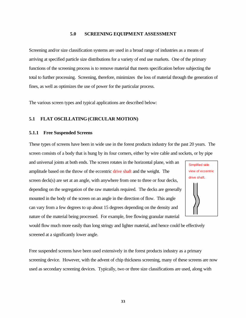
33
5.0 SCREENING EQUIPMENT ASSESSMENT
Screening and/or size classification systems are used in a broad range of industries as a means of
arriving at specified particle size distributions for a variety of end use markets. One of the primary
functions of the screening process is to remove material that meets specification before subjecting the
total to further processing. Screening, therefore, minimizes the loss of material through the generation of
fines, as well as optimizes the use of power for the particular process.
The various screen types and typical applications are described below:
5.1 FLAT OSCILLATING (CIRCULAR MOTION)
5.1.1 Free Suspended Screens
These types of screens have been in wide use in the forest products industry for the past 20 years. The
screen consists of a body that is hung by its four corners, either by wire cable and sockets, or by pipe
and universal joints at both ends. The screen rotates in the horizontal plane, with an
amplitude based on the throw of the eccentric drive shaft and the weight. The
screen deck(s) are set at an angle, with anywhere from one to three or four decks,
depending on the segregation of the raw materials required. The decks are generally
mounted in the body of the screen on an angle in the direction of flow. This angle
can vary from a few degrees to up about 15 degrees depending on the density and
nature of the material being processed. For example, free flowing granular material
would flow much more easily than long stringy and lighter material, and hence could be effectively
screened at a significantly lower angle.
Free suspended screens have been used extensively in the forest products industry as a primary
screening device. However, with the advent of chip thickness screening, many of these screens are now
used as secondary screening devices. Typically, two or three size classifications are used, along with
Simplified side
view of eccentric
drive shaft.

34
fines discharge on the bottom tray. These screens come in a wide range of sizes; ranging from an
approximately 25 square foot deck area to over 300 square feet.
5.1.2 Controlled Throw Screens
Motion on controlled throw screens is much the same as the free suspended horizontal oscillating
screen. With controlled throw screens, however, the screen body is point connected at the corners (or
at a minimum of two corners) through a male/female type raceway that accurately controls the throw
(circular motion) of the screen. Rotex, a very large manufacturer of this type of screen, uses a three
suspension screen with the drive acting as one of the control points at the infeed end of the screen.
One of the advantages claimed for this type of screen is that due to accurate control of the throw, the
screen can provide higher dynamic action on the material and thereby improve the screening efficiency
and the capacity for equivalently- sized screens. However, this type of screen generally requires a
higher initial investment , and may be subject to higher maintenance requirements after extended use.
5.2 SHAKER AND VIBRATORY SCREENS/CONVEYORS
5.2.1 Screen Applications
These screens are characterized by a vertical and forward lifting action, with this motion being derived
from eccentric shafts, mounted and driven in the horizontal plane. Alternatively, the driving action may
be provided by an electric vibrator mounted at the appropriate angle. Drives can either be overhead,
underslung, or sometimes separate units mounted on each side of the screen body.
Typically these screens are mounted on coil springs or synthetic fiber leafs to provide resistance and
spring-back to the driving force being applied.
Shaker and vibratory screens have been more prominently used in the mining, metals, foundry, and
construction industries than the forest products industry due to their much more aggressive action, and
ability to act effectively as feeders as well as screens. However, these types of screens are now finding

35
use in the waste wood reclamation industry as a means of providing a very robust primary separation of
highly contaminated virgin waste materials (tree stumps for example).
5.2.2 Vibratory Screening/Conveying
This technology is now many decades old, and is effectively used in most of the primary processing
industries: forest products, pulp & paper, mining, metal products, coal production, foundries,
construction materials, chemicals, power plants, sanitary processing systems, foods and general
manufacturing, for example.
The philosophy in employing this technology is to effect efficient classification while the raw material is
being conveyed to the next step in the process, thereby minimizing additional handling, equipment, and
costs. This type of system has been extensively used in the sawmill industry for waste wood chipper
infeeds. Typically, waste wood collection conveyor systems in the lower floors of sawmills collect not
only waste wood, but all the sawdust as well. This sawdust not only chokes the chipper, and adds
unnecessary fines to the chips, but can cause accelerated wear on the knives and wear components in
the chipper. A vibratory screener/conveyor, rather than a belt on the infeed to the chipper, discharges
the sawdust before the chipper throat, thereby reducing the chipper loading and wear. Similarly, chips
discharging from the bottom of the chipper may be collected on a vibratory screener/conveyor, whereby
the fines are screened while the chips are conveyed to the takeaway belt to the storage bin or process.
These systems have been fitted with fiberglass trough sections to facilitate the installation of metal
detection devices to protect the process equipment from metal contamination.
Again these systems come in a wide range of size/capacities, either in dynamically balanced construction
for simple bolt-down, or unbalanced, requiring a mass foundation for the resistance loading.
5.2.3 Vibratory Taper-Slot & De-Stoning Screens

36
The action of these screens is the same vertical/forward action of those previously covered, however,
additional features have been added to provide a wider range of material separation.
These features include tapered slots, or finger screens that widen in the direction of material flow,
thereby minimizing any plugging of the slots. This type of screen is generally used for heavy duty coarse,
and widely variable raw materials, such as log yard waste, made up of rocks, gravel bark and wood
chunks of various sizes. The first section of the de-stoner typically provides a coarse scalping and side
shear to discharge log chunks ranging in size from less than a foot up to 10 or 12 feet long. Material
continuing on the screen is then progressively screened by size, and also by weight, at the air-knife
section once the material has been characterized by size. The air-knife section consists of an opening in
the conveyor bottom with an adjustable air knife opening to blow the lighter materials downstream to
continue on the conveyor. The heavier material, rocks, metals, and saturated wood/knots drop-out by
gravity to a side discharge on the conveyor. These types of systems are available in a single or twin air-
knife configuration to provide for a wide range of classification and cleaning.
It should be noted that this system, along with other screening systems, can only clean “free”
contaminants from the parent material, or those contaminants that can be shaken loose in the vibratory
action. In the forest products industry, wet materials are generally much more difficult to screen and
clean than dry material.
5.3 DISC SCALPING SCREENS
Disc scalping screens have been in use for approximately 50 years in some form or another. They
consist of a series of parallel shafts, perpendicular to the material flow, with a series of offset interspacial
discs mounted in overlapping rows on the shafts. Successive shafts, or groups of shafts, are generally
run at higher speeds to provide a "pulling" or separation in the direction of material flow (material flows
perpendicular to the shaft axis).

37
Depending on the desired results, the type, consistency, and contamination of the material being
processed, the disc scalping screen can take on the necessary characteristics to meet the needs of a
particular industry or materials to be processed.
Shafts may be solid, tightly spaced, with small discs, or large pipe torque tubes with large discs and
wide spacing to effect either very fine or alternatively coarse separation depending on requirements.
Discs can also have a variety of contours on the perimeter, as well as different thicknesses, depending
on the materials and the application. Adjacent discs can also be different diameters to facilitate a more
turbulent action of the material on the discs.
In the initial years of chip thickness screening and slicing in the pulp and paper industry, precision disc
screens of various types were used as the primary screen to remove pulp chips greater than 6 to 7 mm
thick (thick chips were then sliced to 7 mm nominally before rejoining the stream to the pulping process.
Because of the tight
tolerance of the shafts and
disc spacing and high
capacity continuous use,
these screens experienced
high maintenance due to
the continuous scrubbing
of wood between the
discs. Although quite a
number of these screens
are still in use, the
machinery suppliers to
this industry have now developed new generation separation systems that are equally refined with regard
to processing capabilities, but much lower in operational and maintenance costs.
Infeed
Rejects
Accepts
Disc Scalping Screen

38
Scalping-type screening systems lend themselves very well to the primary sorting requirements in the
area of waste wood recovery as this is a relatively cost effective way to remove unwanted product size
and contaminants, prior to primary processing.
5.4 TROMMEL SCREENS
5.4.1 Dry Trommel Screens
Trommel or revolving drum screens have been used for many years in many of the primary industries for
cleaning and classification of a wide variety of materials.
These screens can be supplied in a wide range of diameters and lengths, from 3' diameter by 8' long to
12' diameter by 60' long. As many of these types of screens are now mounted on mobile platforms
(fifth wheel low beds), sizes are generally in the 6 to 8' diameter by 30 to 40' long. This type of screen
can be fitted with a wide variety of screen
opening sizes and types; either woven wire
or punched plate. In the longer lengths, the
screen can achieve size classification by
using mesh or opening sizes that are
graduated from small to large as the material
moves toward the discharge end. When
dividers or chutes are placed beneath each
section of the trommel, wood particles
passing through each section of the screen can be effectively segregated. This type of screen is now
being utilized quite extensively for dry cleaning (removal of fines) as well as for classification of mulch
products.
One of the many advantages of the trommel screen is its simplicity; a drum supported on trunnions and
driven at a variety of speeds. The screening action is also excellent because of the lifting and cascading
action of the material. This feature is particularly useful when processing wet and hard to untangle
Rejects& contaminants
Infeed
Accepts
Trommel Screen

39
materials, as well as materials of very wide size range. Trommel screens are used almost exclusively in
the Oriented Strand Board industry to separate fines from the long wood strands after the drying
process. Other types of screens do not provide enough action to separate the fines from the surface of
the wood strands.
5.4.2 Wet Trommel Screens
Trommel screens, because of their action (lifting and cascading) make excellent washers to clean dirt
contaminated materials and de-water them.
The internal construction of the wet system is slightly different than the dry, in that the wet has an internal
ribbon screw to control the forward flow of the wet material. The screen is also fitted with a water
nozzle header to deluge the material as it cascades down the screen.
The disadvantage of this type of system is that very significant water pickup (with wood fiber and bark)
occurs in the process, and if the material is to be used in an application that requires dry material, this
cleaning method may be cost prohibitive.
5.5 VAT TYPE WASHING SYSTEMS
A number of vat-type wood debris washing systems have been developed in the past few years to
address logyard debris clean-up problems. These systems are quite generic in that they consist of a
water containment tub, an overhead means of agitating and moving the floating debris forward, and a
grit collector conveyor that discharges the heavies and rocks; a chain conveyor extracts the cleaned
material from the water bath.
These systems can be very effective in removing rocks, as well as grit that is not imbedded in the surface
of the wood. However, they are generally restricted to use in warmer weather due to freeze-up and
conveyor icing problems in the colder northern climates. Dry systems are also generally preferred for
mobile systems due to environmental considerations.

40
5.6 HYBRID CLEANERS/CLASSIFIERS/DEBARKERS
In the past ten years a a significant amount of time and effort has been spent by those directly involved in
the wood debris recovery industry and equipment suppliers to customize equipment to meet the
demanding needs of this industry, and at the same time try to keep costs under control.
A number of machines that have been developed, and are in use, draw from fairly old and well
developed technology. These include heavy duty rotary drum systems that are a combination of drum
debarker technology and heavy duty trommel screens; combination systems utilizing heavy duty disc
screens followed by conventional drum debarkers; or fixed body debarkers with internal rotors.
There is also another hybrid cleaner/classifier/debarker now finding its way into the market, the Deal
Processor. This patented
machine combines heavy duty
scalping screen technology with
the positive tumbling action found
in drum debarkers. Its multi-
shaft, disc rotors are configured
with the rotor axis in the
longitudinal direction, and the
shafts increasing in elevation, in
section across the machine in the
direction of rotation of the rotors.
Rotors also increase in speed in
the direction of rotation and the
higher elevation. Disc spacing is
fixed at time of manufacture to
effect the piece size classification desired. The operation of the Deal Processor is characterized by
aggressive tumbling of the wood debris material providing quick separation of the waste materials that
Infeed
RockDrop-out
Accepts
Differentialspeed off-set
rotor mounteddiscs
Hybrid Screening Technologies:The Deal ProcessorTM

41
fall between the overlapping discs. The woody material retained above the rotors is effectively cleaned
and debarked as it tumbles, in drum operation fashion toward the discharge. Like a drum debarker, the
discharge is also fitted with an adjustable gate to control the level of material in the machine and the
dwell time to effect the level of cleaning and debarking desired.
5.7 AIR CLASSIFICATION/SEPARATION
Air separation systems that use the density of the materials in a typical mixture have been used for many
years. These systems have been used extensively in chip classification systems after sizing (screening for
size distribution) to remove high density materials such as wet knots and rocks. These systems use a
crude adjustable air nozzle system with an updraft air flow to lift the acceptable product and allow the
"heavies" to drop out into a reject hopper.
Air classification systems can be a very cost effective means of removing heavy contaminants from
classified material in conjunction with pneumatic conveyance to the next stage in the process.

42
6.0 CHIP SAMPLING & PRODUCTION TESTS
Following assembly of initial data on the types of size reduction equipment available, several samples of
processed fiber were gathered. Production tests were designed and executed with the assistance of
Northwest wood processors to assess individual operating parameters. The overriding objective of this
research has been to identify those control parameters with the greater influence on the ability to high
grade currently low value wood waste materials. This section describes the sampling procedures,
overall testing objectives, and the details of each the six individual tests conducted. The methodology
employed for each test is included in the appropriate test description.
6.1 CHIP SAMPLING PROCEDURES
During the course of this study, chip samples were taken from several Northwest wood processing
facilities, each representing different variations in primary reduction equipment used. With dissimilar
facility access and configuration in each case, adaptive sampling procedures were necessary for the
purpose of obtaining a representative sample from each location. The following basic sampling
strategies were used at each facility.
Sampling of processed wood waste chips was achieved directly from storage locations such as
stockpiles, or from conveying units such as a conveyor belts. In each case, a set of sub-samples was
collected (typically 5 gallon buckets) to form a composite sample.
6.1.1 Sub-sample Collection
1) Sampling from conveying units: During chip processing, material samples were taken from conveyer
units at ten minute intervals to ensure that samples were representative of the range of incoming
feedstock. The conveying unit was not stopped to allow sample collection.
2) Sampling from storage piles: Samples were collected at three to five locations from the chip piles in
the storage areas, including the top third, mid third, and bottom third of the stored material.
Material was also retrieved at different depths within the pile.

43
6.1.2 Compositing
The collected sub-samples were combined into a composite sample. The composite sample was then
sub-divided into smaller sample sizes using a quartering procedure. Quartering was conducted on a
clean surface so that foreign material was not introduced.
6.2 SAMPLE ASSESSMENT
Sample # 1: Fixed-Hammer Hog
Nominal Size: 3-inch minus
Produced Geometry: Coarse & fibrous
Comments: Large distribution of small splinters

44
Sample # 2: Swing Hammer Hog
Nominal Size: 3 ½ -inch minus
Produced Geometry: Coarse & fibrous
Comments: Large distribution of small splinters
Sample # 3: Mass Rotor Hog
Nominal Size: 3-inch minus
Produced Geometry: Coarse
Comments: less lengthy chunks than other hogs
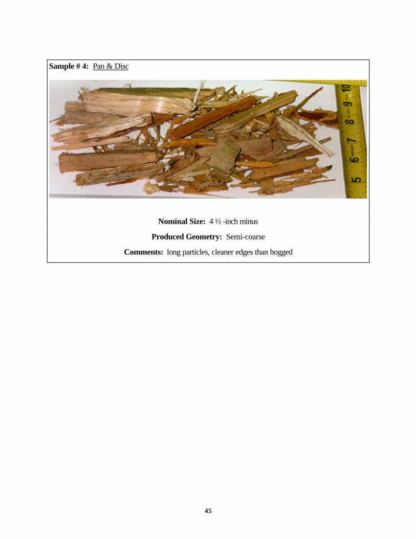
45
Sample # 4: Pan & Disc
Nominal Size: 4 ½ -inch minus
Produced Geometry: Semi-coarse
Comments: long particles, cleaner edges than hogged

46
The samples shown above, along with several other samples collected, illustrate the range of physical
characteristics that processed urban wood “chips” may have, depending on the reduction process used.
Note the similarity of appearance between the various hogged fiber samples number 1, 2 and 3. The
fiber particles seen in these samples can be broadly characterized as coarse and fibrous in nature. The
coarse characteristic refers to the irregular surface geometry produced by the blunt force reduction
action of the hogging process. The fibrous characteristic refers to the way the particles have separated
with the longitudinal grain of the wood and the frayed ends of each particle.
Sample number 4 shows particles produced in a hybrid reduction process termed “pan & disc” by the
manufacturer. These particles are generally coarse and fibrous like samples 1-3, but show fewer frayed
ends and cleaner edges of each particle. This is judged to be a result of the sharper tooling used in the
reduction mechanism, creating more cutting or slicing action, rather than the ripping action of more blunt
tooling (hammers).
Sample # 5: Disc Rechipper
Nominal Size: 2-inch minus
Produced Geometry: Two-sided
Comments: overly fractured

47
Sample number 5 shows particles created in a controlled feed chipping test, using a drop-feed disc
chipper. Note that these particles have a wafer-like geometry. While the particles in this sample do not
have a uniform thickness or width, the overall geometry is reasonably consistent. The parameters of the
test in which these chips were produced is described in the section below. Several issues regarding the
application of chipping technologies to urban wood waste reduction are discussed elsewhere in this
report. The significance of this sample is its demonstration of the ability to produce a particle from the
highly varied geometry of unprocessed urban wood wastes that more closely resembles the geometry of
a virgin wood chip.

48
6.3 TESTING OBJECTIVES
Given the capital intensive nature of wood processing equipment, the ability to customize tests to control
desired parameters is greatly limited. However, tests were designed to draw on currently available
resources within the Northwest wood recycling industry, with minor modifications to process setups.
The following objectives guided test design:
1. Employ Currently Available Technology In Any System Design.
While new technologies continue to develop, it is necessary to develop short-term strategies for
improving industry size reduction practices. Testing and use of this technology, however, needs to
address the following considerations:
• Modified feeding to control the workpiece. The basic chipping principle involves slicing a
piece of wood from a larger mass. This process has been refined to achieve very specific
geometry results because that larger mass (whole logs, for example) can be carefully controlled.
Testing ways of controlling the feed of waste wood in a similar manner, offers the potential for
dramatic improvement in how that fiber is size reduced.
• Modified tooling should be considered that might produce immediate performance results with
currently available equipment.
• Contamination removal practices must be considered in assessing the performance of size
reduction technologies.
• Maintenance protocols need also be addressed, as residual handling equipment has often
historically been left to run until it no longer feeds, rather than rigorously maintained.
2. Maximize Fiber Yield

49
As discussed in earlier sections of this report, maximizing fiber yield, or the amount of wood pieces
meeting production requirement after processing the raw waste wood materials, is a constant challenge.
Fines are a natural byproduct of size reduction, but often cannot be used in the same manufacturing
process, and are in-turn burned or directed to an alternative use at significant cost. In engineering size
reduction processes, the industry seeks to minimize such “fall-down” or fiber loss.
3. Minimize Handling Steps
This is interrelated with maximizing the fiber yield, as each time wood fiber is handled there is typically
some loss. Minimizing handling steps is also critically important to controlling both fixed and variable
process costs in terms of capital equipment and labor costs.6.4
6.4 TEST # 1 - EVALUATION OF HOGGED FIBER SAMPLE
6.4.1 Test Objectives
• Assess the geometry of fiber produced by a typical fixed hammer hog system with ancillary screen
sizing.
• Quantify general size distribution in fraction of overs, accepts and fines produced in a single pass
through system
• Spot check moisture content of a representative sample of processed urban wood fiber
6.4.2 Description
A trial run was conducted at Northwest Wood and Fiber and Recovery (NWWFR) in Auburn,
Washington during August 1996. The NWWFR system configuration consists of a horizontal-feed,
fixed-hammer hog with 3” X 5” discharge grates.
All discharge areas were swept clean. The production process was restarted and a roughly 6,000-
pound sample was run. The sample was reduced in the hog and passed over a flat circular motion
(Rotex-type) screen fitted with a 5/16-inch punched plate and a 1 ½-inch punched plate. This screened
fraction was then weighed to establish percent by weight of the original sample.

50

51
The configuration of the NWWFR system produces three separate size fractions of wood:
1.) fines (-5/16-inch punch plate) -3/8-inch particle size
2.) accepts (+5/16-inch - 1 ½-inch punch plate) +3/8-inch - 3-inch particle size
3.) overs, (+1 ½-inch punch plate) +3-inch particle size
6.4.3 Findings
• Weights were taken of each separate size fraction after the test run, and it was found that 85% of
the sample was accepts, 11% of the sample was fines, and only 4% of the sample was overs. The
following table represents the individual data for each size fraction of wood from the NWWFR
(Auburn) facility
• The urban wood material was tested to be 18 percent wet basis
Table. Relative quantities, ratios, and moisture content of processed sample
Total Pounds Percent of Total Moisture Content(Wet Basis)
Overs (+3 inch) 235 lbs. 4% 17%
Accepts
(+3/8 inch - 3 inch)
5060 lbs. 85% 18%
Fines (-3/8 inch) 631 lbs. 11% 22%
• The size distribution produced in a single pass through the mill, with relatively large discharge grates,
was smaller than anticipated, with only 4 percent by weight retained on the 1 ½” round punch plate.
This demonstrates the way dry wood fiber fractures, or shatters when being hogged.

52
6.5 TEST # 2 - EVALUATION OF CHIPPING EQUIPMENT
6.5.1 Test Objectives
• Evaluate the potential for direct reduction of urban wood via chipping.
• Simulate a modified feed system where oriented pre-crushed wood chunks enter the cutting zone in
a controlled manner
6.5.2 Description
A test was conducted in March 1997 at Northwest Wood & Fiber Recovery using a drop-spout 12
knife disc chipper. In order to safeguard the chipping equipment for the purposes of this test, a
representative sample of urban wood, including pallets, dimensional lumber and plywood was selected
by hand, and all nails and other inorganic contaminants were removed. The sample was then configured
in bundles tied with twine to simulate a feed system where precrushed pieces would be mechanically
oriented and compressed.
Similar type processing is done in certain European wood recycling facilities, first precrushing the urban
wood and then using a modified feed system to orient and contain the pieces as they move into the
cutting plane. These systems use drum style chippers and also may employ modified tooling, including
knife cutting angles, and require more frequent maintenance due to hard contaminants in urban wood.
The sample of roughly 750 pounds. was then fed by hand into the drop spout. Both the anvil setting
(clearance between anvil and knives) and knife quality (sharpness) of the chipper at the time of the test
were known to be outside of optimal operating parameters.
6.5.3 Findings
All of the sample was successfully chipped, and no large pieces were able to pass through without being
reduced, as is typical when feeding smaller pieces. While this test did not address difficulties associated
with retooling to handle embedded inorganic contaminants, it demonstrates the importance of controlled
feed in obtaining successful chipping of urban wood.

53
6.6 TEST # 3 - EVALUATION OF HYBRID EQUIPMENT
6.6.1 Test Objectives
• The objective of this test was to assess the geometry of urban wood fiber processed with this
equipment.
• Further, this test was designed to evaluate the maximum obtainable particle size distribution, that
would continue to provide the reduction needed to free a large fraction of embedded metal
contamination (nails, screws, etc.).
6.6.2 Description
A test was conducted at Rainier Wood Recyclers of Kent, Washington in April 1997. Rainier uses a
Contender grinder from Universal Refiner that employs a patented Pan & Disc reduction system. The
Universal Refiner design orients the wood as it is reduced allowing it to achieve the longitudinal
fracturing of the raw urban wood necessary to free a majority of the embedded metals for subsequent
removal, through the use of magnets and other ancillary cleaning and screening. This test was able to
produce a fiber particle that was 7-inch minus, no overs, with 15 percent fines production, for a yield of
85 percent.
6.6.3 Findings
• The geometry of fiber chunks produced by this equipment are clearly less coarse than fiber from a
conventional hog (see sample #4 above).
• Longitudinal fiber fracturing successfully freed a high percentage of the embedded metal
contamination. No large chunks of dimensional lumber with screws or nails were evident.

54
6.7 TEST # 4-A EVALUATION OF RE-CHIPPING EQUIPMENT (SEPTEMBER 1996)
6.7.1 Test Objectives
• Assess the performance of a straight-knife drum chipper in handling the over size chunks produced
by primary reduction through a fixed hammer hog.
6.7.2 Description
For this test, a 500 pound sample of overs (+3-inch ) taken from Northwest Wood & Fibre
Recovery’s, Auburn hog line was processed in a drop-spout straight-knife drum (SKD) re-chipper.
The sample was first washed in a standard chip washer at a Boise Cascade particleboard mill. The
infeed belt to the chipper was fitted with a magnet to extract ferrous metal before the material was fed
into the chipper. Additionally, during the course of feeding the sample through the chipper,
approximately 2-3 dozen wood pieces with nails and/or staples imbedded within were extracted. The
approximate moisture content of the overs being fed into the chipper was 15% on a wet basis.
6.7.3 Findings
• Particles produced were more coarse than the desired two-sided wafer like chips produced by
conventional chipping.
• Two factors were suspected of causing the poor performance:
• Lack of particle orientation achieved during feeding
• Very low moisture content led to “shattering” effect of brittle material during chipping.
6.8 TEST # 4-B EVALUATION OF RE-CHIPPING EQUIPMENT (APRIL 1997)
6.8.1 Test Objectives
• Assess the performance of a straight knife drum in handling urban wood processed to 7 inch minus
through primary reduction in a pan and disc system.
• Test modified feeding options, including vibratory in-feed conveyor, coupled with alignment ribs in
drop feed spout.

55
• Test influence of cutting tolerance settings on consistency of size.
6.8.2 Description
For this test, a 300 pound sample of 7-inch minus urban wood fiber from Rainier Wood Recyclers was
run in a drop-spout straight-knife drum (SKD) re-chipper. In this test, a vibratory feed conveyor was
employed to orient pieces prior to entering the infeed opening, and the drop-spout was modified with
ribbing to maintain piece orientation.
Two runs were conducted. In the first run, the anvil was set to produce an 1 1/2-inch minus chip.
Several particles were allowed to pass through the equipment without being properly chipped, yielding
an average particle geometry that was not significantly improved from that of the original sample. For
the second test run on this machine, the knife projection was adjusted to produce a smaller chip. With
the tighter tolerances, a more uniform quality chip was successfully produced.
6.8.3 Findings
• Particle orientation is a significant control parameter in the chipping process. Chunks reduced in
this test were cut more uniformly than those in Test 4-A.
• Control of workpiece also appears to be of significant importance, short pieces tend to bounceand
loose orientation upon entering the cutting zone.
6.9 TEST #4-C EVALUATION OF RE-CHIPPING EQUIPMENT (JUNE 97: NICHOLSON
ROTODRUM RE-CHIPPER @ NICHOLSON - SYDNEY, BC)
6.9.1 Test Objectives
• Assess the performance of a rotodrum chipper in handling urban wood processed to 7 inch minus
through primary reduction in a pan and disc system.
• Assess the shattering effect in a tight tolerance cutting zone
• Assess chip quality and cut orientation in a rotodrum versus a straight-knife chipper

56
6.9.2 Description
For this test, a 350 pound sample of 7-inch minus urban wood fiber from Rainier Wood Recyclers
(from TEST #3) was run in a drop-spout rotodrum re-chipper. This drum chipper machine has 52 tri-
edged knives mounted in an offset pattern across the drum. The rotodrum works against a serrated
anvil along with a bottom grate to control sizing, although a majority of the accepts are directed by the
knives into the drum and discharged from the core.
6.9.3 Findings
• The fiber sample processed in this test shattered under the knives of the re-chipper rather than being
cut, demonstrating again the influence of low moisture content on reduction performance of urban
wood waste, even under sharp tooling.

57
7.0 CONCLUSIONS AND RECOMMENDATIONS FOR SECONDARY WOOD
FIBER RECOVERY
The wood recycling industry is facing a time when biomass fuel markets are declining due to long term
shifts in fuel sources and air quality considerations, while access to fiber markets is limited by the ability
of processors to engineer the reduction process to meet specifications. Hogging technologies are clearly
appropriate for a wide range of applications, including biomass fuel, mulch, and several other mid-value
applications discussed above that do not require extensive quality control or sizing. In regions of the
country where those markets are prevalent, such hog based wood recycling systems are likely to
continue to be long-term viable. However, in parts of the country where fiber markets exist, there is an
emphasized need to develop new systems.
Based on the process tests conducted and fiber samples evaluated in the course of this study, it is
believed that chipping and hybrid reduction technologies offer the greatest potential for processors to
bring product closer in quality to that of virgin wood chips, thus developing a more stable market
position within the framework of market demand for chips from residuals.
7.1 TECHNICAL BARRIERS
Technical barriers that currently exist are that of unsuitable chipper cutter (knife type) and feeding
methodology to control the workpiece while it is being chipped. Many years of experience tells us that
in order to produce a quality chip there are some basic criteria that must be met:
• the workpiece must be held as secure as possible
• knives must be kept in good condition (sharp)
• machine set-up must be maintained (anvil condition and setting).
None of these conditions can be met employing standard currently available chippers. However, there
has not previously been a major push by the industry to develop equipment which achieves these
objectives in the processing of historically low value waste wood. Current chipping and re-chipping
technologies have served the forest based industries well for many decades, however it is now

58
imperative that these technologies be reassessed with the objective of possible modifications to better
serve and to be more directly applicable to the recyclers needs, either in primary or secondary
recovery applications.
7.2 RECOMMENDATIONS TO OVERCOME TECHNICAL BARRIERS
The first step to help overcome technical barriers is to test current state-of-the-art available tooling
metallurgy, not only that which has been generic to wood chipping (sawing) applications, but tooling
metallurgy in general, used in may industries; mining, roadbuilding, construction, metals, etc.
Extensive research and development work has been focused on hard-rock tunnelling, and roadway
scarification to develop cutter technology that would withstand this harsh environment. It is from this
technology that we should draw from to develop customized tooling suitable and applicable to chipper
application for primary and secondary size reduction of CDL materials.
There are a number of steps that are recommended to firstly gain acceptance of this concept, and
secondly to prove that it is economically viable, cost competitive, and can give the desired results.
7.2.1 Modified Tooling
Conceptually and technically there is no reason why systems cannot be developed to provide effective
size reduction of CDL materials, employing chipper technology, with the end product objective being
that of a chip approximating size and quality of a pulp-type chip. The absence of chipping technologies
in domestic wood waste processing is most likely because of the economics, both real and perceived.
Modified tooling and downtime for knife changing have real costs which must be compared with the
marginal increase in value that may be realized for chips of higher quality. With increases in long-term
chip pricing and expanding infrastructure for the recovery of urban wood wastes, we may be reaching a
point in the domestic industry where the application of such technology will be considered economically
feasible, as it has in other parts of the world such as Eastern Europe.

59
The catalyst to effect this type of change is the identification of a real need within the industry and
acknowledged support (financial) for such a program. With this, the equipment manufacturers / suppliers
could then proceed with a test pilot program (contributing to the cost) to progressively test chipper
designs, by gradually introducing metal contaminated wood in conventional chippers that have been
outfitted with modified tooling for increased durability. Such a system would not tolerate large tramp
metal chunks, however, by far the largest percentage of metal contaminants found in urban wood wastes
take the form of nails, staples, small brackets, and steel banding.
7.2.2 Chipper Feed System
Whether chipping is used for primary or secondary reduction, (re-chipping), the key to producing a
quality chip is control of the workpiece while it is in the cutting zone. As an example, this is rather easy
to achieve while chipping whole virgin pulp logs as the mass of the log relative to the cutting forces is
such that there is little movement of the log at the knife face while it is being cut. On the other hand, if we
look at trying to chip a waste pallet for example, the first challenge is how can, or should it be fed to the
chipper. Effective chipping requires that wood be cut across the grain at a relatively shallow angle,
certainly not parallel to the grain which could happen in a large throat chipper processing CDL materials
not properly prepared for chipping.
The challenge here, when dealing with bulky, fabricated woody materials, is to develop a feed system
that would be able to accept bulk loading, as is the present practice with the feed systems to large
primary hogs. Such a feed system could compress and align the fiber generally in the longitudinal
direction (direction of feed and perpendicular to the knife cutting circle), and positively hold the material
mass as it is fed into the knife circle.
We believe that this feed concept is conceptually sound both for potential chipper application for
primary reduction as well as for secondary, re-chipping. The feed system would be different, however,
the concept of alignment of fiber and holding it while cutting would be the same.

60
Material sizing is interdependent with a modified feed system, in that primary sizing is a function of the
ability to align and hold the material as it is being chipped. The quality of chip is directly impacted by the
tooling configuration, amount of metal contamination, moisture level and species of wood. If a heavy
duty drum-type chipper is employed, it can be fitted with a grizzly or basket screen on the bottom to
minimize overs in the finished product.
7.2.3 Equipment Operation
Proper operation of size reduction equipment is often assumed, however, in practice, residual recovery
equipment is often managed much less stringently than other manufacturing equipment. Poor
maintenance practices lead to reduced through-put rates, and dramatically degraded geometry of
reduced material . The following recommendations are made by equipment vendors and industry
engineers:
• Operators must understand wood waste recovery equipment and know their particular machine.
This includes what proper cutting tolerances are, and the various means of adjustment.
• Develop and follow routine maintenance schedules which match the type of materials and
corresponding wear that the equipment experiences.
• Train operations staff on what perform indicators to look for, that should trigger inspections and
adjustments.
7.3 FUTURE DIRECTIONS
This study has identified operating parameters to be considered in developing appropriate size reduction
strategies for wood waste recovery. Research in the industry is ongoing, and will require time to evolve.
Critical to this development is communication between wood waste generators, collectors, processors,
and end-users about process requirements. Technology transfer occurring between the different
elements which comprise the wood processing industry, is encouraged, and will speed this process.

61
8.0 ACKNOWLEDGMENTS
This report was prepared by the Clean Washington Center, with funding from the state of Washington
and the U.S. Commerce Department’s National Institute of Standards and Technology (NIST). The
Clean Washington Center is the Managing Partner of the Recycling Technology Assistance Partnership
(ReTAP), an affiliate of NIST’s Manufacturing Extension Partnership (MEP).
The Center would like to gratefully acknowledge the following for their work as the principal authors of
this report:
1. John Yeasting, Re-Sourcing Associates, Inc., 6100 Southcenter Blvd. Seattle, Washigton
98188. (206) 246-9821
2. Al Hume, CPM Consultants, Inc., 4th Floor - 509 Richards Street, Vancouver, B.C. Canada
V6B 2Z6. (604) 684-1911.
In addition, valuable in-kind support was provided by the following companies:
1. Boise Cascade Corporation, One Jefferson Place, Boise, Idaho 83728. (208) 384-6161
2. Northwest Wood & Fibre Recovery, Dan Walsh, 32300 148th Way SE, Auburn, WA 98002.
(253) 939-5497.
3. Rainier Wood Recyclers , Bob Sargent, 27529 Covington Way SE, Kent, WA 98042. (253)
630-3565
4. VK Brunette, Ian Corrigall, 330 Edworthy Way, New Westminster, B.C., Canada, V3L 5G5
5. Nicholson Manufacturing Company, 3670 East Marginal Way S., Seattle, Washington 98134.
(206) 682-2752.
62
9.0 BIBLIOGRAPHY
9.1 ARTICLES BY AUTHOR
A. Simons Ltd. “Review of State-of-the-Art Technology: Chip Preparation,” AF-IndustrinsProcesskonsult AB., Towards Kraft Mill 2000, Book 2: 5-7 (Oct. 1991).
Agricultural Experiment Station, Oregon State University. “Technical and Economic Considerations forUtilizing Industrial and Urban Wood Wastes as Wood Fiber Extenders in Oregon’s PanelboardPlants.”, Special Report 940, October 1994.
American Forest & Paper Association. “National Wood Recycling Directory.” First Edition, January,1996.
Aquino, John T. “The Tale of the Tub Grinder.” In Waste Age, April 1996, pp 114.
Biocycle. “Recovery Options for Wood and C&D.” In Biocycle “Diverting Wood from Landfills”issue, July 1995, pp. 30.
Biryukov, M. V. Petri, V. N. “Effect of Cutting Speed on Properties of Chips for Production of Pulp”VUZ, Lesn. Zh. no. 2: 59-61 (1983). [Russ.] cf. ABIPC 55: abstr. 7846. [Engl. transl. Available]
Blackman, T. “Recycling: Not Just for Papers and Bottles Anymore” Forest Industries, For. Ind. 118,no. 8: 18-19 (Oct. 1991).
Brickner, Robert H. “Researching Debris Generation.” In Recycling Today, September 1995, pp.46-53.
Brooks, S. H. W. “Valuable Products That Can Be Manufactured from Urban-Generated WoodFiber, Glass, and Plastic” Recycling Symp. (New Orleans) Notes: 373-376 (TAPPI; Feb. 28-March 4,
Broughton, Anne Claire. “New Heights in C&D Recycling.” In Recycling Today, March 1996, pp.28.
Conrad, Paul. “Urban Wood Markets in the Northwest.” In Biocycle, November 1995, pp. 70.
Davis, Eugene, “Investigation of Alternative Markets for Recycled Wood.” Prepared for MetropolitanService District, Portland, OR, 1993.
Davis, Patricia. “In the Chips: Ponderay Valley Fibre, Inc.” Forest Product Equipment Magazine,September 1996.

63
Dubois, M. “Chips Produced at Sawmills; Manufacturing Chips Off-Site” Auburn University, 1994TAPPI Chip Preparation and Quality Short Course: Course Notes (TAPPI Press)
Dubois, M. R., Wagner, F. G. “Sawmill Chip Survey in the Southeastern US: Analysis of Processesand Chip Quality” Mississippi State University. TAPPI Pulping Conf. (Orlando) (Book 1): 481-484 (Nov. 3-7, 1991).
Edelman, J. S. “Effect of Disk Speed on Sawmill-Residue Wood-Chip Quality” Virginia PolytechnicInstitute & State University, Pulping Conf. (Boston) Proc. (Book 1): 375-380 (TAPPI; Nov. 1-5,1992).
Environmental Protection Agency. “Paper Products Recovered Materials Advisory Notice (RMAN).”Document Number EPA530-Z-96-005, May 1996.
Firmin, Larry. “Recycling in the Construction Industry: New Uses for C&D Waste.” In WasteBusiness Magazine, January/February 1996, pp. 5-8.
Fryer, Alex P. “Shortage of wood pulp forces forays into foreign forests.” In Puget Sound BusinessJournal, March 24-30, 1995,.pp 4.
Grant, Bob. “Taking the Long View Column.” In Encore, a newsletter of Longview FibreCompany, San Francisco, CA, Summer 1995.
Harler, Curt. “Pulling Down Profits From Wood Debris.” In Recycling Today, March 1996, pp. 56.
Horne-Brine, Preston. “Washington Pioneers Wood Recycling.” In Recycling Today, May 1995, pp.50.
Howard, J. “Debarking and Chipping; Taking the Show on the Road” Finning Ltd., Mill Prod. News6, no. 5: 12-13 (September/October 1995).
Ingham, Daniel. “Is there a tub grinder in your future?” In Resource Recycling, August 1995, pp 30.
Kerstetter, James D. and Deshaye, Joyce A. “1994 Washington State Directory of Biomass EnergyFacilities” Washington State Energy Office, March 1994.
Kuhn, Dr. D.C.S. “Wood Fibre and Particulate Motion in Complex Flows.” The Department ofChemical Engineering and Applied Chemistry, University of Toronto, 1996.
Lumpkin, Russ. “Wood Waste Recovery Services: Grinding Out An Idea” Forest ProductsEquipment Magazine, August 1996.
Manfredi, Frank. “Grinders come out of the woods.” In Machinery Outlook, 1996.

64
Marrs, Gevan R. “Chip Screening Performance Index.” Presentation Paper, Research andDevelopment Project Manager, Weyerhaeuser Paper Company, Tacoma, Washington.
McElvenny, Jim J. “Adding Value to Recycled Wood.” In C&D Debris Recycling, Spring 1995, pp.6.
McPhee, Marnie. “C&D Recycling in the Home Court.” In. Biocycle, March 1996, pp.30
O’Brien, Kathleen. “Business Built on Construction Recycling.” In In Business, November/December1995, pp. 37.
O'Connor, B. “Chip Preparation Methods and Their Application on Frozen Chips” Consilium BulkInc., TAPPI Pulping Conf. (Toronto) Proc. (Book 2): 873-878 (Oct. 14-17, 1990).
Popov, N.I. “Wear-Resistant Chipper Knives with Inserted Elements” ; TsNIIMOD. Vereshchagin,D. Yu.; TsNIIMOD., Derevoobrab. Promst. no. 2: 3-4 (1992). [Russian]
Porter, Doug. “The Life and Times of a Wood Recycling Company.” In Biocycle, April 1996, pp. 36.
Puikki, Reino. “Harvest systems and wood quality: Effects from stump to final product.” CanadianPulp & Paper Association (CPPA) Woodlands Paper, Lakehead University School of Forestry.
Robinson, M. “Chipping,” Carthage Machine Co., Chip Preparation Quality Seminar SaratogaSprings, NY Notes: 119, 121-204 (CPPA/TAPPI, June 23-24)
Robinson, M. D. “Optimizing Chip Quality Through Understanding and Controlling Chipper DesignCharacteristics” Carthage Machine Co., TAPPI Pulping Conf. (Seattle) Proc. (Book 1): 325-338 (Oct. 22-25, 1989).
Stoves, G. D. “Chip Thickness Control with a Conventional Screening System Using Chip GradingTechniques” Rust International Corp, Tappi Journal. 74, no. 9: 293-296 (Sept. 1991).
Stringer, G. E. “Knife Holder for Wood Chippers” Can. pat. 1,262,622. Issued Nov. 7, 1989. 4claims. 15 p. Cl.29-36. Filed: Can. appln. 512,65
Stuart, W. B. “Effect of Trim Block Length on Chip Quality” Virginia Polytechnic Institute & StateUniversity, Pulping Conf. (Atlanta) Proc. (Book 2): 735-740 (TAPPI; Nov. 1-3, 1993).
Stuart, W. B. “Factors Affecting Sawmill-Residue Chip Quality” Virginia Polytechnic Institute & StateUniversity, TAPPI Pulping Conf. (Orlando) (Book 1): 485-492 (Nov. 3-7, 1991).
White, Kathleen. “Growing with Wood Waste.” In Waste Age, May 1995, pp. 59.

65
9.2 ARTICLES BY TITLE
“A Maturing Infrastructure,” Recycling Today, August 1995
“Achievement and Significance of Optimal Chip Quality,” TAPPI Journal, February 1996
“Chip Thickness Screening with and Oscillating Bar Screen,” TAPPI Journal, November 1991
“Fundamental Aspects of Wood Chipping,” TAPPI Journal, October 1995
“Mining the Urban Forest,” Wood and Wood Products, May 1996
“Quantification of Factors Affecting Chip Quality from Disc Chippers,” TAPPI Journal, October 1992
“Reciprocating Blade Screen for Improved Chip Thickness Screening,” TAPPI Journal, June 1993
“TAPPI Chip Preparation and Quality Short Course,” TAPPI Journal, June 1996
“Trends in Chip Thickness Screening,” TAPPI Journal, September 1990
“Triangular Hammers Improve Shredder’s Efficiency,” Design News, June 3, 1991
“Wood Waste - Not the Same Old Grind,” Wood and Wood Products, June 1996
“Wood Waste Chipper, etc. Guide,” Waste Age, March 1995, March 1996
9.3 OTHER REFERENCE SOURCES
Personal Communication with Lanse Richardson, Fiber Procurement Manager, Boise CascadeCorporation, December 1996, and February 1997.
Personal Communication with Terry Gillis, General Manager, Recovery One, Tacoma, WA, February1997.
Personal Communication with Carl Simpson, Fiber Procurement Manager, Stone ConsolidatedNewsprint Mill, Steilacoom, WA, May 1997.
Personal Communication with Duane Good, Regional Fiber Procurement, Boise Cascade Corporation,April 1997.
Personal Communication with Bill Wright, Heartwood Consulting, April 1997.

66
Specifications and Information Discussions:• Port Townsend Paper, Port Townsend, Washington• Simpson Tacoma Kraft, Tacoma, Washington• Smurfit Newsprint Company, Eugene, Oregon• Willamette Industries, Eugene, Oregon
Product Literature and Informational Discussions:• Acrowood Corporation, Everett Washington• BlowApCo, Germantown, Wisconsin• Deal Processor - see Valon Kone Brunette, Ltd.• Diamond Z Manufacturing, Nampa, Idaho• Jeffrey / Indresco, Marietta, Georgia• Pallman Pulverizers, Clifton, New Jersey• Peterson Pacific, Eugene, Oregon• Universal Refiner, Montesano, Washington• Universal Wear Parts, Mississippi• Valon Kone Brunette, Ltd., Vancouver, British Columbia, CANADA• West Salem Machinery, Salem, Oregon• Williams Patent Crusher, St. Louis, Missouri