Wns-00284 Antenna Sweep Test-NEW
45
Wireless Network Services AASSTS: MOP and Acceptance Requirements AT&T WIRELESS CONFIDENTIAL & PROPRIETARY Use pursuant to Company instructions © 2002 AT&T Wireless Services, Inc. 1 Document WNS-00284 Rev. 3.0 10/24/02 AWS Antenna Systems Sweep Testing Standard: MOP and Acceptance Requirements Document Number WNS-00284 Rev. 3.0 10/24/02 Overview This document describes the method of procedures for antenna system sweep testing and acceptance requirements for all AWS antenna and coax systems – Global Positioning System (GPS), Location Measurement Unit (LMU), Angle of Arrival (AOA), and Base Transceiver Station (BTS) Systems. It focuses on the use of standard setup and calibration techniques to establish the necessary criteria that determines the validity of the antenna systems being tested. Recording and saving the data is important for future sweep tests. The Antenna Systems Site Submission Forms are the documents that should be used to record sweep test results and system configuration data. Contents 1. Purpose of Antenna System Sweep Testing............................................ 7 2. Antenna System Testing Process ............................................................ 8 3. Antenna System Test Sceniros .............................................................. 10 3.1 New Antenna System .................................................................... 10 3.2 Existing Antenna System............................................................... 10 3.3 LMU Antenna System.................................................................... 10 3.4 GPS Antenna System.................................................................... 11
-
Upload
tonyislammahazam -
Category
Documents
-
view
90 -
download
6
description
sweep test
Transcript of Wns-00284 Antenna Sweep Test-NEW
Wireless Network Services AASSTS: MOP and Acceptance Requirements
AT&T WIRELESS CONFIDENTIAL & PROPRIETARY Use pursuant to Company instructions
© 2002 AT&T Wireless Services, Inc. 1 Document WNS-00284 Rev. 3.0 10/24/02
AWS Antenna Systems Sweep Testing Standard: MOP and Acceptance Requirements
Document Number WNS-00284 Rev. 3.0 10/24/02
Overview
This document describes the method of procedures for antenna system sweep testing and acceptance requirements for all AWS antenna and coax systems – Global Positioning System (GPS), Location Measurement Unit (LMU), Angle of Arrival (AOA), and Base Transceiver Station (BTS) Systems. It focuses on the use of standard setup and calibration techniques to establish the necessary criteria that determines the validity of the antenna systems being tested.
Recording and saving the data is important for future sweep tests. The Antenna Systems Site Submission Forms are the documents that should be used to record sweep test results and system configuration data.
Contents 1. Purpose of Antenna System Sweep Testing............................................ 7 2. Antenna System Testing Process ............................................................ 8 3. Antenna System Test Sceniros .............................................................. 10
3.1 New Antenna System .................................................................... 10 3.2 Existing Antenna System............................................................... 10 3.3 LMU Antenna System.................................................................... 10 3.4 GPS Antenna System.................................................................... 11
Wireless Network Services AASSTS: MOP and Acceptance Requirements
AT&T WIRELESS CONFIDENTIAL & PROPRIETARY Use pursuant to Company instructions
© 2002 AT&T Wireless Services, Inc. 2 Document WNS-00284 Rev. 3.0 10/24/02
3.5 AOA Antenna System.................................................................... 11 4. Tools and Equipment.............................................................................. 12 5. Antenna System Test Cases.................................................................. 13
5.1 Return Loss of Antenna: Verify Antenna Quality........................... 13 5.2 Return Loss - 50Ω LOAD: Verify System Cable Quality ............... 14 5.3 DTF - 50Ω LOAD: Check System Cable Components.................. 15 5.4 Return Loss - SHORT: Measure System Cable Insertion Loss .... 16 5.5 DTF - SHORT: Measure System Cable Length ............................ 17 5.6 Return Loss – Verify Complete Antenna System.......................... 18 5.7 DTF – Measure Complete Antenna System.................................. 20 5.8 Verify Quality of Additional Jumpers.............................................. 21 5.9 Miscellaneous RF Equipment Verification..................................... 21
6. Reporting and Deliverables .................................................................... 22 7. Appendix A: Sample Site Turn-over Package........................................ 23 8. Appendix B: SiteMaster Setup and Calibration Procedure .................... 31
8.1 Return Loss Mode – “A”, “B”, or “C” SiteMaster® Model .............. 31 8.2 Distance-to-Fault (DTF) Setup ...................................................... 33
9. Appendix C: Existing System - Sweep Test M&P’s ............................... 34 9.1 Pre-Sweep Requirements ............................................................. 34 9.2 Pre-Sweep Without Planned Tower Top Work.............................. 34
9.2.1 Free Up Complete Antenna System..................................... 34 9.2.2 Re-Use Complete Antenna System ..................................... 36
9.3 Pre-Sweep With Planned Tower Top Work................................... 36 9.3.1 Free Up Complete Antenna System..................................... 37 9.3.2 Re-Use Complete Antenna System ..................................... 39
9.4 Waivers or Variances .................................................................... 39 10. Appendix D: All Test Sceniero Limit References ................................... 40 11. Appendix E: Typical Cable Loss Reference Tables ............................... 41 12. Appendix F: Antenna System Site Submission Forms........................... 42
Wireless Network Services AASSTS: MOP and Acceptance Requirements
AT&T WIRELESS CONFIDENTIAL & PROPRIETARY Use pursuant to Company instructions
© 2002 AT&T Wireless Services, Inc. 3 Document WNS-00284 Rev. 3.0 10/24/02
Figures
Figure 1: Antenna System Test Suite Process ............................................... 9 Figure 2: Test Cable System Quality ............................................................ 14 Figure 3: Measure System Cable Insertion Loss.......................................... 16 Figure 4: Verify Complete Antenna System - Basic...................................... 18 Figure 5: Return Loss w/50Ω Load - Example Sweep.................................. 24 Figure 6: Distance to Fault w/50Ω Load - Example Sweep......................... 25 Figure 7: Return Loss w/Short - Example Sweep........................................ 26 Figure 8: Distance to Fault w/Short - Example Sweep ................................. 27 Figure 9: Return Loss Complete Antenna System – Example1 Sweep ....... 28 Figure 10: Return Loss Complete Antenna System – Example 2 Sweep .... 29 Figure 11: Distance to Fault Complete Antenna System - Example Sweep 30 Figure 12: Verify Complete Antenna System w/Duplexer ............................ 35 Figure 13: Verify Complete Antenna System w/Duplexer & Diplexer........... 38
Tables
Table 1: Antennas – Loss Value Limit .......................................................... 13 Table 2: Cellular Uplink and Downlink Frequency Ranges .......................... 31 Table 3: PCS Uplink and Downlink Frequency Ranges ............................... 32 Table 4: GPS Uplink Frequency Ranges...................................................... 32 Table 5: Test Scenieros – Loss Value Limit ................................................. 40 Table 6: Andrew – Typical Cable Loss Values ............................................. 41 Table 7: Commscope – Typical Cable Loss Values ..................................... 41 Table 8: RF Components – Typical Loss Values.......................................... 41
Wireless Network Services AASSTS: MOP and Acceptance Requirements
AT&T WIRELESS CONFIDENTIAL & PROPRIETARY Use pursuant to Company instructions
© 2002 AT&T Wireless Services, Inc. 4 Document WNS-00284 Rev. 3.0 10/24/02
Document Revision History
Date Revision Description Approved By
03/01/01 1.0 First release. Sidney Roberts
03/12/01 1.1 Section 2.8 added to document. Sidney Roberts
04/06/01 1.2 Additional 1900 info added. Sidney Roberts
07/20/01 2.0 Document revised and rewritten.
Re-issued for review.
Out for Review Only.
08/30/01 2.1 Additional diagrams included and an example site sweep turnover package is included.
Sidney Roberts
02/05/02 2.2 Revised tables, RL parameters and Section 6. Added Appendix B. Revised Site Submission Form.
Sidney Roberts
02/08/02 2.3 Technical editor revisions.
Added Appendix C for the Antenna Feedline System Site Submission Form.
Sidney Roberts
09/10/02 2.4 Additional process flow diagram, updates to existing systems sweep and clarification of Antenna Quality Tests, GPS and LMU added.
Out for Review
10/02/02 2.5 AOA section added, GPS/LMU and AOA Site Submission Forms
Out for Review
10/18/02 2.6 Additional comments from review. Issued to Technical Writing Team
Ray Butler
10/24/02 3.0 Updated front matter, fixed some links, and some general edits
Ray Butler
Wireless Network Services AASSTS: MOP and Acceptance Requirements
AT&T WIRELESS CONFIDENTIAL & PROPRIETARY Use pursuant to Company instructions
© 2002 AT&T Wireless Services, Inc. 5 Document WNS-00284 Rev. 3.0 10/24/02
Contacts
For questions or comments about this document’s technical content or to request changes to the document, contact:
Gregory Long, AT&T Wireless Services WNS National Radio Technology Support desk: 425-580-8633 e-mail: mailto:[email protected]
Acknowledgments
We are pleased to acknowledge the contributions of the following individuals who provided their expertise to make this document possible.
• Brett Seriani, AT&T Wireless • Mark Zamalloa, Arva Hudson
• Mike Glidewell, Bechtel • Bob Francis, Bechtel
• Greg Scharosch, AT&T Wireless • Karl Beck, AT&T Wireless
• Dr. Russell Dearnley, Andrew Corp.
Trademarks
The following trademarks or registered trademarks for products are discussed in this document:
SiteMaster ® is a registered trademark of Anritsu, Inc.

Wireless Network Services AASSTS: MOP and Acceptance Requirements
AT&T WIRELESS CONFIDENTIAL & PROPRIETARY Use pursuant to Company instructions
© 2002 AT&T Wireless Services, Inc. 6 Document WNS-00284 Rev. 3.0 10/24/02
For Additional Copies
This document and other WNS documents are available from the WNS Online Library at:
http://wns.sc.attws.com/wns_library/default.htm
If you do not have access to the Intranet location, or if you have difficulty printing the document, contact:
WNS National Librarian desk: 425-702-2823 e-mail: [email protected]
mail to: WNS National Librarian Wireless Network Services AT&T Wireless Services, Inc. PO Box 97059 Redmond, WA 98073-9759
Note: Printed copies of this information are uncontrolled and could be obsolete.
Copyright © 2002 by AT&T Wireless Services, Inc.
All rights reserved. No part of the contents of this document may be reproduced or transmitted in any form without the written permission of the publisher.
Wireless Network Services AASSTS: MOP and Acceptance Requirements
AT&T WIRELESS CONFIDENTIAL & PROPRIETARY Use pursuant to Company instructions
© 2002 AT&T Wireless Services, Inc. 7 Document WNS-00284 Rev. 3.0 10/24/02
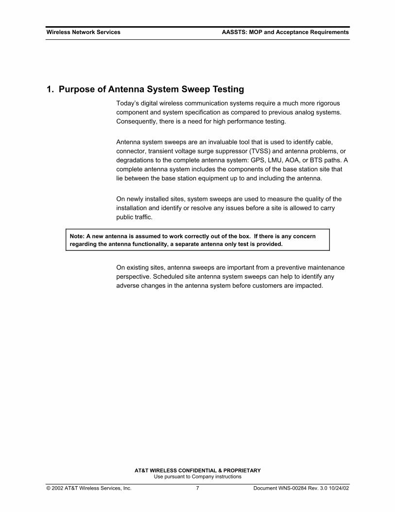
1. Purpose of Antenna System Sweep Testing Today’s digital wireless communication systems require a much more rigorous component and system specification as compared to previous analog systems. Consequently, there is a need for high performance testing.
Antenna system sweeps are an invaluable tool that is used to identify cable, connector, transient voltage surge suppressor (TVSS) and antenna problems, or degradations to the complete antenna system: GPS, LMU, AOA, or BTS paths. A complete antenna system includes the components of the base station site that lie between the base station equipment up to and including the antenna.
On newly installed sites, system sweeps are used to measure the quality of the installation and identify or resolve any issues before a site is allowed to carry public traffic.
Note: A new antenna is assumed to work correctly out of the box. If there is any concern regarding the antenna functionality, a separate antenna only test is provided.
On existing sites, antenna sweeps are important from a preventive maintenance perspective. Scheduled site antenna system sweeps can help to identify any adverse changes in the antenna system before customers are impacted.
Wireless Network Services AASSTS: MOP and Acceptance Requirements
AT&T WIRELESS CONFIDENTIAL & PROPRIETARY Use pursuant to Company instructions
© 2002 AT&T Wireless Services, Inc. 8 Document WNS-00284 Rev. 3.0 10/24/02
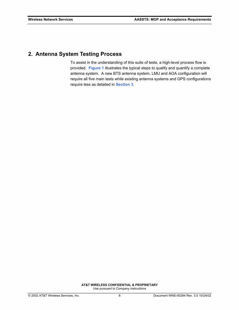
2. Antenna System Testing Process To assist in the understanding of this suite of tests, a high-level process flow is provided. Figure 1 illustrates the typical steps to qualify and quantify a complete antenna system. A new BTS antenna system, LMU and AOA configuration will require all five main tests while existing antenna systems and GPS configurations require less as detailed in Section 3.

Wireless Network Services AASSTS: MOP and Acceptance Requirements
AT&T WIRELESS CONFIDENTIAL & PROPRIETARY Use pursuant to Company instructions
© 2002 AT&T Wireless Services, Inc. 9 Document WNS-00284 Rev. 3.0 10/24/02
Figure 1: Antenna System Test Suite Process
Conduct Test:"Verify System Cable Quality"
Section 5.2
Conduct Test:"Check System Cable Components"
Section 5.3
Begin
Are all the AntennasNew?
Is antenna betterthan Table 1 criteria?
Are all componentsbetter than -25dB
criteria?
Is Coax System betterthan -20dB criteria?
No
Does Antenna Systempass -15.5 dB criteria?
Yes
Yes
Yes
No
Yes
No
Replace Bad Antenna
No
No
Testing Complete
Log Jumpers & MainFeedline Cable Lengths
Log InsertionLoss Value
FixFault
FixFault
CompleteReports
Conduct Test on reused Antenna:"Verify Antenna Quality "
Section 5.1
Conduct Test:"Measure System Cable Insertion Loss"
Section 5.4
Conduct Test:"Measure System Cable Length"
Section 5.5
Conduct Test:"Verify Complete Antenna System Quality"
Section 5.6
Conduct Test:"Measure Complete Antenna System"
Section 5.7
Yes
Wireless Network Services AASSTS: MOP and Acceptance Requirements
AT&T WIRELESS CONFIDENTIAL & PROPRIETARY Use pursuant to Company instructions
© 2002 AT&T Wireless Services, Inc. 10 Document WNS-00284 Rev. 3.0 10/24/02
3. Antenna System Test Sceniros The purpose is to provide guidance required when performing sweep tests for New, Existing, LMU, GPS, or AOA Antenna Systems.
3.1 New Antenna System Perform sweep test Section 5.2 and Section 5.4 through Section 5.7 at the appropriate frequency band, Table 2 or Table 3. Complete BTS Antenna System Site Submission Form.
The results of sweep tests shall be provided to AWS, or AWS’s authorized representative, as part of the site turnover documentation in accordance with Section 6.
3.2 Existing Antenna System Refer to Appendix C - Section 9. Complete BTS Antenna System Site Submission Form.
The results of sweep tests shall be provided to AWS, or AWS’s authorized representative, as part of the site turnover documentation in accordance with Section 6.
3.3 LMU Antenna System Perform sweep test Section 5.2 and Section 5.4 through Section 5.7 at the appropriate frequency band, Table 2 or Table 3. Complete GPS/LMU Antenna System Site Submission Form.
The results of sweep tests shall be provided to AWS, or AWS’s authorized representative, as part of the site turnover documentation in accordance with Section 6.
Wireless Network Services AASSTS: MOP and Acceptance Requirements
AT&T WIRELESS CONFIDENTIAL & PROPRIETARY Use pursuant to Company instructions
© 2002 AT&T Wireless Services, Inc. 11 Document WNS-00284 Rev. 3.0 10/24/02
3.4 GPS Antenna System Perform sweep test Section 5.2, Section 5.4, and Section 5.5 at the appropriate GPS frequency range, Table 4. Complete GPS/LMU Antenna System Site Submission Form.
The results of sweep tests shall be provided to AWS, or AWS’s authorized representative, as part of the site turnover documentation in accordance with Section 6.
3.5 AOA Antenna System Perform sweep test Section 5.2 and Section 5.4 through Section 5.7 at the appropriate frequency band, Table 2 or Table 3. Complete AOA Antenna System Site Submission Form.
Note: Bypass the Calibration Splitter for all Calibration Antenna System tests.
The results of sweep tests shall be provided to AWS, or AWS’s authorized representative, as part of the site turnover documentation in accordance with Section 6.
Wireless Network Services AASSTS: MOP and Acceptance Requirements
AT&T WIRELESS CONFIDENTIAL & PROPRIETARY Use pursuant to Company instructions
© 2002 AT&T Wireless Services, Inc. 12 Document WNS-00284 Rev. 3.0 10/24/02
4. Tools and Equipment There are several manufacturers for spectrum and network analyzers. AT&T Wireless will not disqualify any manufacturer nor sweep testing results that are completed using equipment other than what is outlined in this standard document. Currently, this document recommends the use of either the S331/332 A/B/C, S235/251 A/B/C, S400A SiteMaster® models manufactured by Anritsu, Inc. (formerly Wiltron).
Other equipment required to complete the sweep tests:
• Precision 7/16 DIN 50 Ω Open/Short/Load
• One 7/16 DIN (or N) male-to-female adapter
• One 7/16 DIN female-to-female adapter
• Two-way radio for communication between the testing technicians located at the top of the antenna support structure and at the testing point
• 10’-0” long, ½”diameter coax jumper with one 7/16 DIN male connector located at each end of the jumper. (This is only required if the bottom jumper is not already installed into the antenna feedline system.)
• Connector torque wrench, i.e. Andrew Part#: 244377
Test equipment shall be allowed to stabilize in test environment prior to calibration for a minimum of thirty minutes, and shall be recalibrated at a minimum of every two hours and after any change in environment, to ensure accuracy.
NOTE: ENSURE ALL CALIBRATION EQUIPMENT IS CLEAN AND VOID OF ANY DEBRIS OR ANY OBVIOUS SIGNS OF MECHANICAL DAMAGE OR DEFECTS.
CAUTION: IT IS REQUIRED THAT ALL SITEMASTER® & LOAD EQUIPMENT BE CERTIFIED AND VERIFIED BY AN AUTHORIZED CALIBRATION FACILITY ON AN ANNUAL BASIS. IF REQUESTED, PROOF OF CALIBRATION SHALL BE SUBMITTED TO AWS OR AWS’s DESIGNATED REPRESENTATIVE.

Wireless Network Services AASSTS: MOP and Acceptance Requirements
AT&T WIRELESS CONFIDENTIAL & PROPRIETARY Use pursuant to Company instructions
© 2002 AT&T Wireless Services, Inc. 13 Document WNS-00284 Rev. 3.0 10/24/02
5. Antenna System Test Cases
5.1 Return Loss of Antenna: Verify Antenna Quality This step is strongly recommended for all antennas, but only required to verify the quality of a reused antenna that is being installed. By testing all antennas before mounting onto the antenna support structure eliminates any possibility of rework and cost that may occur due to a faulty antenna.
1. Configure the SiteMaster® for RETURN LOSS by either recalling the saved Return Loss Setup for the frequency band of interest or performing the steps outlined in Section 8.1.
2. Set LIMIT LINE based upon antenna type, Table 1.
Table 1: Antennas – Loss Value Limit
Antenna Type Return Loss Frequency Range
Omni & AOA -14 dB 824 MHz – 892 MHz
or
1850 MHz – 1975 MHz
Cellular Panel -16.5 dB 824 MHz – 892 MHz
PCS Panel -17 dB 1850 MHz – 1975 MHz
UMTS/PCS Panel -15 dB 1710 MHz – 2150 MHz
3. Verify CAL ON is displayed at top left of display.
4. For Panels, ensure that antenna is elevated at least 3’-0” above the ground, away from any metalic objects and in a face-up position. For optimal results when positioning Omnis, place antenna in a vertical orientation clear of any obstacles.
5. Locate the peaks across the entire manufactureres band (between M1 & M2 receive and M3 & M4 transmit) and verify that the sweep in these bands are below the return loss value limit line defined in Table 1.
6. Verify all antennas are acceptable prior to installation.
Wireless Network Services AASSTS: MOP and Acceptance Requirements
AT&T WIRELESS CONFIDENTIAL & PROPRIETARY Use pursuant to Company instructions
© 2002 AT&T Wireless Services, Inc. 14 Document WNS-00284 Rev. 3.0 10/24/02
5.2 Return Loss - 50Ω LOAD: Verify System Cable Quality
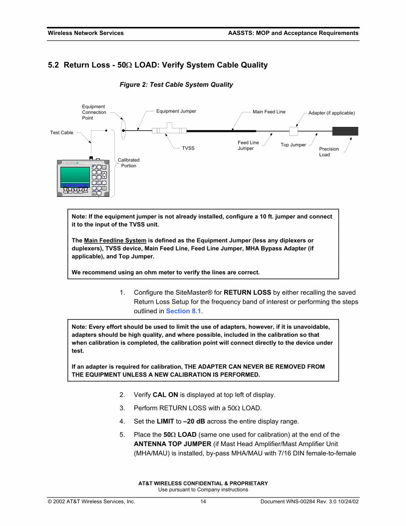
Figure 2: Test Cable System Quality
Site Master S331A
STARTCAL
3
RECALLDISPLAY
0
1
MARKER
8
AUTOSCALE
2
SAVESETUP
5RECALLSETUP
6
CAL 4
LIMIT
7
SAVEDISPLAY
9
ONOFF
ESCAPECLEAR
RUNHOLD
ENTER
.
FREQ POWER
DIST SCALE
OPT
Site Master S331ASite Master S331A
STARTCAL
3STARTCAL
3
RECALLDISPLAY
0RECALLDISPLAY
0
11
MARKER
8MARKER
8
AUTOSCALE
2
AUTOSCALE
2
SAVESETUP
5SAVESETUP
5RECALLSETUP
6RECALLSETUP
6
CAL 4CAL 4
LIMIT
7LIMIT
7
SAVEDISPLAY
9SAVEDISPLAY
9
ONOFFONOFFONOFF
ESCAPECLEARESCAPECLEAR
RUNHOLDRUN
HOLD
ENTER
ENTER
.
FREQ POWER
DIST SCALE
OPT
FREQFREQ POWER
POWER
DISTDIST SCALE
SCALE
OPT
OPT
Equipment Jumper Adapter (if applicable)
PrecisionLoad
Feed LineJumper
Top Jumper
Main Feed Line
TVSS
Test Cable
EquipmentConnectionPoint
CalibratedPortion
Note: If the equipment jumper is not already installed, configure a 10 ft. jumper and connect it to the input of the TVSS unit.
The Main Feedline System is defined as the Equipment Jumper (less any diplexers or duplexers), TVSS device, Main Feed Line, Feed Line Jumper, MHA Bypass Adapter (if applicable), and Top Jumper.
We recommend using an ohm meter to verify the lines are correct.
1. Configure the SiteMaster® for RETURN LOSS by either recalling the saved Return Loss Setup for the frequency band of interest or performing the steps outlined in Section 8.1.
Note: Every effort should be used to limit the use of adapters, however, if it is unavoidable, adapters should be high quality, and where possible, included in the calibration so that when calibration is completed, the calibration point will connect directly to the device under test.
If an adapter is required for calibration, THE ADAPTER CAN NEVER BE REMOVED FROM THE EQUIPMENT UNLESS A NEW CALIBRATION IS PERFORMED.
2. Verify CAL ON is displayed at top left of display.
3. Perform RETURN LOSS with a 50Ω LOAD.
4. Set the LIMIT to –20 dB across the entire display range.
5. Place the 50Ω LOAD (same one used for calibration) at the end of the ANTENNA TOP JUMPER (if Mast Head Amplifier/Mast Amplifier Unit (MHA/MAU) is installed, by-pass MHA/MAU with 7/16 DIN female-to-female

Wireless Network Services AASSTS: MOP and Acceptance Requirements
AT&T WIRELESS CONFIDENTIAL & PROPRIETARY Use pursuant to Company instructions
© 2002 AT&T Wireless Services, Inc. 15 Document WNS-00284 Rev. 3.0 10/24/02
adapter) and measure RETURN LOSS.
6. If the value is above the –20 dB limit line anywhere across the sweep range, use the DISTANCE-TO-FAULT, Section 5.3 as a troubleshooting aid to identify the questionable component and repair or replace as necessary. Remeasure RETURN LOSS and verify the reading is below the –20 dB limit line across the entire sweep range.
7. Using marker function place M2 to peak.
8. SAVE THE DISPLAY to memory and record PEAK value of M2 on Antenna Feedline System Site Submission Form.
a. Press SAVE DISPLAY key (#9 key) and enter name (“B” Models) or choose memory location 1-40 (“A” or earlier models).
b. Press ENTER.
9. Proceed to Section 5.4.
5.3 DTF - 50Ω LOAD: Check System Cable Components 1. Configure SiteMaster® for DTF – RETURN LOSS by either recalling the
saved DTF SETUP for the frequency band of interest or performing the steps outlined in Section 8.2.
2. Using DTF AID verify:
a. CABLE type is correct (predominant cable type installed).
b. D1 and D2 (D2 should be set to at least 20% greater than the maximum line length to test).
c. RESOLUTION is set to 130 points Greater than 300 ft. RES=517 pts.
d. Select CALIBRATION VALID from display and press ENTER.
3. Set the LIMIT to –25 dB across the entire display range.
4. If the value is above the –25 dB limit line anywhere across the sweep range, identify the questionable component and repair or replace as necessary.
5. SAVE THE DISPLAY to memory.
a. Press SAVE DISPLAY key (#9 key) and enter name (“B” Models) or choose memory location 1-40 (“A” or earlier models).
b. Press ENTER.
6. Return to Section 5.2.

Wireless Network Services AASSTS: MOP and Acceptance Requirements
AT&T WIRELESS CONFIDENTIAL & PROPRIETARY Use pursuant to Company instructions
© 2002 AT&T Wireless Services, Inc. 16 Document WNS-00284 Rev. 3.0 10/24/02
5.4 Return Loss - SHORT: Measure System Cable Insertion Loss
Figure 3: Measure System Cable Insertion Loss
Site Master S331A
STARTCAL
3
RECALLDISPLAY
0
1
MARKER
8
AUTOSCALE
2
SAVESETUP
5RECALLSETUP
6
CAL 4
LIMIT
7
SAVEDISPLAY
9
ONOFF
ESCAPECLEAR
RUNHOLD
ENTER
.
FREQ POWER
DIST SCALE
OPT
Site Master S331ASite Master S331A
STARTCAL
3STARTCAL
3
RECALLDISPLAY
0RECALLDISPLAY
0
11
MARKER
8MARKER
8
AUTOSCALE
2
AUTOSCALE
2
SAVESETUP
5SAVESETUP
5RECALLSETUP
6RECALLSETUP
6
CAL 4CAL 4
LIMIT
7LIMIT
7
SAVEDISPLAY
9SAVEDISPLAY
9
ONOFFONOFFONOFF
ESCAPECLEARESCAPECLEAR
RUNHOLDRUN
HOLD
ENTER
ENTER
.
FREQ POWER
DIST SCALE
OPT
FREQFREQ POWER
POWER
DISTDIST SCALE
SCALE
OPT
OPT
Equipment Jumper Adapter (if applicable)
PrecisionShort
Feed LineJumper
Top Jumper
Main Feed Line
TVSS
Test Cable
EquipmentConnectionPoint
CalibratedPortion
Note: If the equipment jumper is not already installed, configure a 10 ft. jumper and connect it to the input of the TVSS unit.
The Main Feedline System is defined as the Equipment Jumper (less any diplexers or duplexers), TVSS device, Main Feed Line, Feed Line Jumper, MHA Bypass Adapter (if applicable), and Top Jumper.
1. Configure the SiteMaster® for RETURN LOSS by either recalling the saved Return Loss Setup for the frequency band of interest or performing the steps outlined in Section 8.1.
2. Verify CAL ON is displayed at top left of display.
3. Place the SHORT (same one used for calibration) at the end of the ANTENNA TOP JUMPER (if MHA/MAU is installed, by-pass MHA/MAU with 7/16 DIN female-to-female adapter) and measure RETURN LOSS.
4. Select AUTO SCALE to zoom in display.
5. Using the Marker function of the SiteMaster®, place M1 to PEAK and M2 to VALLEY.
6. Determine cable loss by adding M1+M2 value and dividing by four:
(M1+M2/4 = one-way cable insertion loss)
7. Record value in SITE SUBMISSION FORM.
Wireless Network Services AASSTS: MOP and Acceptance Requirements
AT&T WIRELESS CONFIDENTIAL & PROPRIETARY Use pursuant to Company instructions
© 2002 AT&T Wireless Services, Inc. 17 Document WNS-00284 Rev. 3.0 10/24/02
8. SAVE THE DISPLAY to memory.
a. Press SAVE DISPLAY key (#9 key) and enter name (“B” Models) or choose memory location 1-40 (“A” or earlier models).
b. Press ENTER.
9. Proceed to Section 5.5.
5.5 DTF - SHORT: Measure System Cable Length
1. Configure SiteMaster® for DTF – RETURN LOSS by either recalling the saved DTF SETUP for the frequency band of interest or performing the steps outlined in Section 8.2.
2. Using DTF AID verify:
a. CABLE type is correct (predominant cable type installed).
b. D1 and D2 (D2 should be set to at least 20% greater than the maximum line length to test).
c. RESOLUTION is set to 130 points Greater than 300 ft. RES=517 pts.
d. Select CALIBRATION VALID from display and press ENTER.
3. Measure & record cable lengths by placing M1 to peak and recording cable length value in the Antenna System Site Submission Form. Should be at or near zero dB and is the length for the entire cable line as measured.
4. SAVE THE DISPLAY to memory.
a. Press SAVE DISPLAY key (#9 key) and enter name Model “B” or choose memory location 1-40 Model “A” or earlier.
b. Press ENTER.
5. Proceed to Section 5.6.

Wireless Network Services AASSTS: MOP and Acceptance Requirements
AT&T WIRELESS CONFIDENTIAL & PROPRIETARY Use pursuant to Company instructions
© 2002 AT&T Wireless Services, Inc. 18 Document WNS-00284 Rev. 3.0 10/24/02
5.6 Return Loss – Verify Complete Antenna System
Figure 4: Verify Complete Antenna System - Basic
Site Master S331A
STARTCAL
3
RECALLDISPLAY
0
1
MARKER
8
AUTOSCALE
2
SAVESETUP
5RECALLSETUP
6
CAL 4
LIMIT
7
SAVEDISPLAY
9
ONOFF
ESCAPECLEAR
RUNHOLD
ENTER
.
FREQ POWER
DIST SCALE
OPT
Site Master S331ASite Master S331A
STARTCAL
3STARTCAL
3
RECALLDISPLAY
0RECALLDISPLAY
0
11
MARKER
8MARKER
8
AUTOSCALE
2
AUTOSCALE
2
SAVESETUP
5SAVESETUP
5RECALLSETUP
6RECALLSETUP
6
CAL 4CAL 4
LIMIT
7LIMIT
7
SAVEDISPLAY
9SAVEDISPLAY
9
ONOFFONOFFONOFF
ESCAPECLEARESCAPECLEAR
RUNHOLDRUN
HOLD
ENTER
ENTER
.
FREQ POWER
DIST SCALE
OPT
FREQFREQ POWER
POWER
DISTDIST SCALE
SCALE
OPT
OPT
Test Cable
EquipmentJumper
MHA/MAU(if applicable)
Feed LineJumper Top Jumper
Main Feed Lline
Antenna
TVSS
EquipmentConnectionPoint
CalibratedPortion
Note: The Complete Antenna System is defined to include the following equipment: Equipment jumper, TVSS device, Main Feed Line, Feed Line Jumper, MHA/MAU (if applicable), Top Jumper, and Antenna.
Note: If the equipment jumper is not already installed, configure a 10 ft. jumper and connect it to the input of the TVSS unit.
Wireless Network Services AASSTS: MOP and Acceptance Requirements
AT&T WIRELESS CONFIDENTIAL & PROPRIETARY Use pursuant to Company instructions
© 2002 AT&T Wireless Services, Inc. 19 Document WNS-00284 Rev. 3.0 10/24/02
1. Connect the Antenna to the Top jumper. If a MHA exists, connect Main Fead Line jumper to the MHA input and Top jumper to the MHA output, Figure 4, measure RETURN LOSS.
2. Set LIMIT LINE to –15.5 dB across entire display.
3. If antenna system does not include a MHA or Duplexer, proceed to Step 6.
4. With a MHA and/or a Duplexer in-line, verify between markers (M3 and M4 Transmit) that the display is below the –15.5 dB LIMIT LINE.
5. With only a Duplexer in line, MHA not included, also verify between markers (M1 and M2 Receive) that the display is below the –15.5 dB LIMIT LINE, Proceed to Step 7.
6. With-out a MHA or Duplexer in line, verify between markers (M1 and M4) that the display is below the –15.5 dB LIMIT LINE.
Note: Contact Equipment Vendor if the above results fail to meet the required –15.5 dB goal.
7. SAVE THE DISPLAY to memory.
a. Press SAVE DISPLAY key (#9 key) and enter name (“B” Models) or choose memory location 1-40 (“A” or earlier models).
b. Press ENTER.
8. Proceed to Section 5.7.

Wireless Network Services AASSTS: MOP and Acceptance Requirements
AT&T WIRELESS CONFIDENTIAL & PROPRIETARY Use pursuant to Company instructions
© 2002 AT&T Wireless Services, Inc. 20 Document WNS-00284 Rev. 3.0 10/24/02
5.7 DTF – Measure Complete Antenna System 1. Configure SiteMaster® for DTF – RETURN LOSS by either recalling the
saved DTF SETUP for the frequency band of interest or performing the steps outlined in Section 8.2.
2. Using DTF AID verify:
a. CABLE type is correct (predominant cable type installed).
b. D1 and D2 (D2 should be set to at least 20% greater than the maximum line length to test).
c. RESOLUTION is set to 130 points Greater than 300 ft. RES=517 pts.
d. Select CALIBRATION VALID from display and press ENTER.
3. Display DISTANCE-TO-FAULT for the entire antenna feedline system. This sweep will be used in the future as a baseline to track any changes in the cable system and to increase the ability to identify potential problems early and correctly.
4. SAVE the DISPLAY to memory.
a. Press SAVE DISPLAY key (#9 key) and enter name (“B” Models) or choose memory location 1-40 (“A” or earlier models).
b. Press ENTER.
5. Testing Complete.
6. Proceed to Section 6.
Wireless Network Services AASSTS: MOP and Acceptance Requirements
AT&T WIRELESS CONFIDENTIAL & PROPRIETARY Use pursuant to Company instructions
© 2002 AT&T Wireless Services, Inc. 21 Document WNS-00284 Rev. 3.0 10/24/02
5.8 Verify Quality of Additional Jumpers Using the same tests outlined in Section 5.2, verify the quality of all additional jumpers or provide copies of manufacturing test data.
For LMR-240 cables used on TDMA BTS ports use an N (m) to TNC (f) adapter and SMA (f) load.
5.9 Miscellaneous RF Equipment Verification 1. The MHA/MAU is to be verified at Depot level prior to distribution to the field.
2. Using the same tests outlined in Section 5.2, verify all miscellaneous RF equipment (diplexers, duplexers, filters, etc.), at minimum, meet the manufacturer’s specifications. These tests need to be performed prior to installation into the antenna feedline system. Copies of these tests should be included when submitting final sweep test results.
Wireless Network Services AASSTS: MOP and Acceptance Requirements
AT&T WIRELESS CONFIDENTIAL & PROPRIETARY Use pursuant to Company instructions
© 2002 AT&T Wireless Services, Inc. 22 Document WNS-00284 Rev. 3.0 10/24/02
6. Reporting and Deliverables The appropriate completed Antenna System Site Submission Form(s) -
“BTS”, “GPS/LMU”, and “AOA” shall be faxed to the AWS Construction Manager or AWS’s designated representative, within 24 hours of completion of the tests.
Each antenna path shall have at least 5 graphs, except GPS systems:
1. Return Loss – 50Ω LOAD, Section 5.2
2. Return Loss – SHORT, Section 5.4
3. Distance-to-Fault – SHORT, Section 5.5
4. Return Loss – Complete Antenna System, Section 5.6
5. Distance-to-Fault – Complete Antenna System, Section 5.7
Three (3) hard copies (printouts) of tests performed for all AT&T Wireless antennas, miscellaneous RF equipment, and pre-manufactured jumpers located at the site. Two (2) sets shall be provided to the AWS Construction Manager or AWS’s designated representative and one (1) set shall remain safely at the site.
One (1) soft copy (electronic copy) of the tests performed for all AT&T Wireless antennas located at the site shall be provided to the AWS Construction Manager or AWS’s designated representative.
Filename format should follow this guideline: <Base Station Site Name>.dat
Where the “Base Station Site Name” is the naming convention that is provided by the local AWS team.
A completed Site Submission Form Set. All fields must be completed. Any missing data must be explained in the Notes section.
It is strongly recommended that all technicians operating test equipment shall obtain or attend a certified user’s training class before operating the equipment that is required in order to perform the required tests. Class scheduling can be obtained at: http://www.us.anritsu.com/products/testnmeasure/rfnmic/sitemaster/

Wireless Network Services AASSTS: MOP and Acceptance Requirements
AT&T WIRELESS CONFIDENTIAL & PROPRIETARY Use pursuant to Company instructions
© 2002 AT&T Wireless Services, Inc. 23 Document WNS-00284 Rev. 3.0 10/24/02
7. Appendix A: Sample Site Turn-over Package
The purpose of Appendix A is to provide an example of format and layout of completed sweeps in the Site Turn-over Package. Each antenna system tested will have a set of sweeps as defined in Section 6.
Wireless Network Services AASSTS: MOP and Acceptance Requirements
AT&T WIRELESS CONFIDENTIAL & PROPRIETARY Use pursuant to Company instructions
© 2002 AT&T Wireless Services, Inc. 24 Document WNS-00284 Rev. 3.0 10/24/02
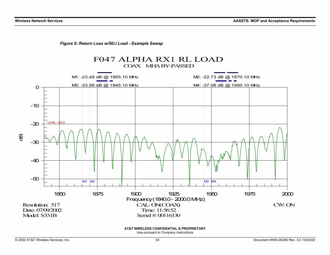
Figure 5: Return Loss w/50Ω Load - Example Sweep
-50
-40
-30
-20
-10
0
1850 1875 1900 1925 1950 1975 2000
Limit : -20.0
M1 M2 M3 M4
F047 ALPHA RX1 RL LOADCOAX MHA BY-PASSED
Model: S331B Serial #: 00116130Date: 07/09/2002 Time: 11:56:52Resolution: 517 CAL: ON(COAX) CW: ON
dB
Frequency (1840.0 - 2000.0 MHz)
M1: -23.48 dB @ 1865.10 MHz M2: -22.73 dB @ 1870.10 MHz
M3: -33.98 dB @ 1945.10 MHz M4: -37.08 dB @ 1950.10 MHz

Wireless Network Services AASSTS: MOP and Acceptance Requirements
AT&T WIRELESS CONFIDENTIAL & PROPRIETARY Use pursuant to Company instructions
© 2002 AT&T Wireless Services, Inc. 25 Document WNS-00284 Rev. 3.0 10/24/02
Figure 6: Distance to Fault w/50Ω Load - Example Sweep
-50
-45
-40
-35
-30
-25
-20
-15
-10
-5
0
0 10 20 30 40 50 60 70 80 90 100 110
Limit : -25.0
F047 ALPHA RX1 DTF LOADCOAX MHA BY-PASSED
Model: S331B Serial #: 00116130 Prop.Vel:0.890Date: 07/09/2002 Time: 11:57:39 Ins.Loss:0.013dB/ftResolution: 517 CAL: ON(COAX) CW: ON
dB
Distance (0.0 - 110.0 Feet)
Wireless Network Services AASSTS: MOP and Acceptance Requirements
AT&T WIRELESS CONFIDENTIAL & PROPRIETARY Use pursuant to Company instructions
© 2002 AT&T Wireless Services, Inc. 26 Document WNS-00284 Rev. 3.0 10/24/02
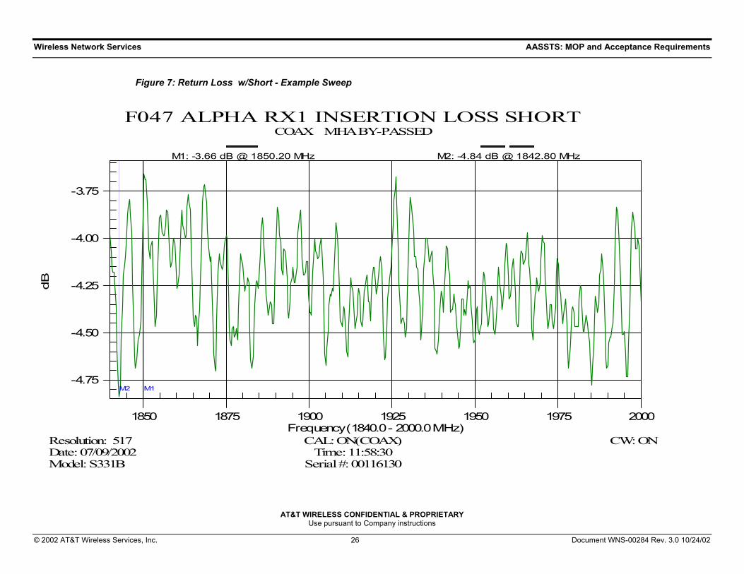
Figure 7: Return Loss w/Short - Example Sweep
-4.75
-4.50
-4.25
-4.00
-3.75
1850 1875 1900 1925 1950 1975 2000
M1M2
F047 ALPHA RX1 INSERTION LOSS SHORTCOAX MHA BY-PASSED
Model: S331B Serial #: 00116130Date: 07/09/2002 Time: 11:58:30Resolution: 517 CAL: ON(COAX) CW: ON
dB
Frequency (1840.0 - 2000.0 MHz)
M1: -3.66 dB @ 1850.20 MHz M2: -4.84 dB @ 1842.80 MHz
Wireless Network Services AASSTS: MOP and Acceptance Requirements
AT&T WIRELESS CONFIDENTIAL & PROPRIETARY Use pursuant to Company instructions
© 2002 AT&T Wireless Services, Inc. 27 Document WNS-00284 Rev. 3.0 10/24/02
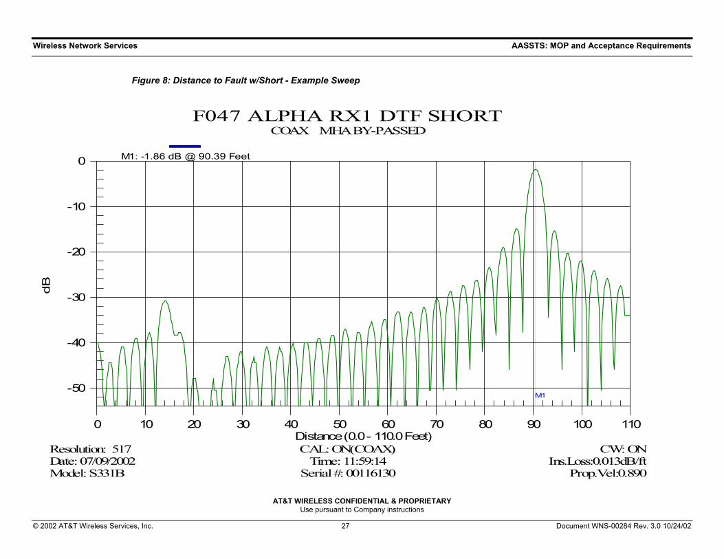
Figure 8: Distance to Fault w/Short - Example Sweep
-50
-40
-30
-20
-10
0
0 10 20 30 40 50 60 70 80 90 100 110
M1
F047 ALPHA RX1 DTF SHORTCOAX MHA BY-PASSED
Model: S331B Serial #: 00116130 Prop.Vel:0.890Date: 07/09/2002 Time: 11:59:14 Ins.Loss:0.013dB/ftResolution: 517 CAL: ON(COAX) CW: ON
dB
Distance (0.0 - 110.0 Feet)
M1: -1.86 dB @ 90.39 Feet
Wireless Network Services AASSTS: MOP and Acceptance Requirements
AT&T WIRELESS CONFIDENTIAL & PROPRIETARY Use pursuant to Company instructions
© 2002 AT&T Wireless Services, Inc. 28 Document WNS-00284 Rev. 3.0 10/24/02
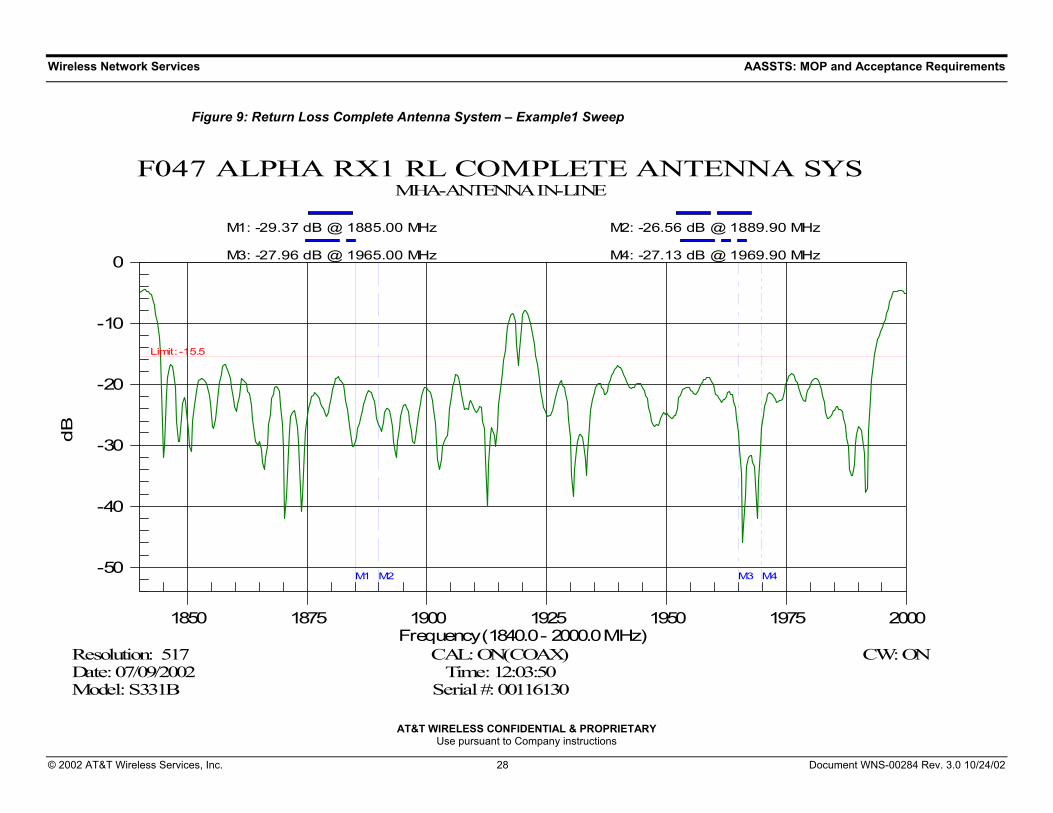
Figure 9: Return Loss Complete Antenna System – Example1 Sweep
-50
-40
-30
-20
-10
0
1850 1875 1900 1925 1950 1975 2000
Limit : -15.5
M1 M2 M3 M4
F047 ALPHA RX1 RL COMPLETE ANTENNA SYSMHA-ANTENNA IN-LINE
Model: S331B Serial #: 00116130Date: 07/09/2002 Time: 12:03:50Resolution: 517 CAL: ON(COAX) CW: ON
dB
Frequency (1840.0 - 2000.0 MHz)
M1: -29.37 dB @ 1885.00 MHz M2: -26.56 dB @ 1889.90 MHz
M3: -27.96 dB @ 1965.00 MHz M4: -27.13 dB @ 1969.90 MHz

Wireless Network Services AASSTS: MOP and Acceptance Requirements
AT&T WIRELESS CONFIDENTIAL & PROPRIETARY Use pursuant to Company instructions
© 2002 AT&T Wireless Services, Inc. 29 Document WNS-00284 Rev. 3.0 10/24/02
Figure 10: Return Loss Complete Antenna System – Example 2 Sweep
-50
-40
-30
-20
-10
0
1850 1875 1900 1925 1950 1975 2000
Limit : -15.5
M1 M2 M3 M4
Site ID Sector ID Cable ID COMPLETE ANTENNA SYSTEMTVSS- ANTENNA IN-LINE
Model: S331B Serial #: 00050168Date: 07/13/2002 Time: 15:57:20Resolution: 259 CAL: ON(COAX) CW: ON
dB
Frequency (1840.0 - 2000.0 MHz)
M1: -32.40 dB @ 1865.40 MHz M2: -27.13 dB @ 1870.40 MHz
M3: -30.17 dB @ 1945.40 MHz M4: -25.85 dB @ 1950.40 MHz

Wireless Network Services AASSTS: MOP and Acceptance Requirements
AT&T WIRELESS CONFIDENTIAL & PROPRIETARY Use pursuant to Company instructions
© 2002 AT&T Wireless Services, Inc. 30 Document WNS-00284 Rev. 3.0 10/24/02
Figure 11: Distance to Fault Complete Antenna System - Example Sweep
-50
-45
-40
-35
-30
-25
-20
-15
-10
-5
0
0 10 20 30 40 50 60 70 80 90 100 110
F047 ALPHA RX1 DTF COMPLETE ANTENNA SYSMHA-ANTENNA IN-LINE
Model: S331B Serial #: 00116130 Prop.Vel:0.890Date: 07/09/2002 Time: 12:04:32 Ins.Loss:0.013dB/ftResolution: 517 CAL: ON(COAX) CW: ON
dB
Distance (0.0 - 110.0 Feet)

Wireless Network Services AAFSST: MOP and Acceptance Requirements
AT&T WIRELESS CONFIDENTIAL & PROPRIETARY Use pursuant to Company instructions
© 2002 AT&T Wireless Services, Inc. 31 Document WNS-00284 Rev. 3.0 10/24/02
8. Appendix B: SiteMaster Setup and Calibration Procedure
8.1 Return Loss Mode – “A”, “B”, or “C” SiteMaster® Model 1. Connect test port extension cable to reflection port and ensure connection is
tight.
2. Press ON/OFF to turn on SiteMaster®.
3. Press ENTER.
4. Press MODE.
5. Select FREQ – RETURN LOSS.
6. Select F1 soft key and type reference Table 2, Table 3, or Table 4.
7. Press ENTER.
8. Select F2 soft key and type reference Table 2, Table 3, or Table 4.
9. Press ENTER.
10. Press MARKERS.
11. Select M1 soft key.
12. Select EDIT soft key and set M1 to value as noted in the appropiate table.
13. Select BACK soft key. Model “B” only.)
14. Perform the same process setting M2, M3, and M4 as noted in the appropiate table.
Table 2: Cellular Uplink and Downlink Frequency Ranges
Cellular Frequency
Band
F1 Soft Key
F2 Soft Key
Uplink Frequency Range (MHz) Markers 1 & 2
Downlink Frequency Range (MHz) Markers 3 & 4
A 810 910 824 – 847 868 - 892
B 810 910 835 – 850 880 - 895
Wireless Network Services AAFSST: MOP and Acceptance Requirements
AT&T WIRELESS CONFIDENTIAL & PROPRIETARY Use pursuant to Company instructions
© 2002 AT&T Wireless Services, Inc. 32 Document WNS-00284 Rev. 3.0 10/24/02
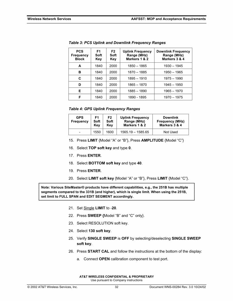
Table 3: PCS Uplink and Downlink Frequency Ranges
PCS Frequency
Block
F1 Soft Key
F2 Soft Key
Uplink Frequency Range (MHz) Markers 1 & 2
Downlink Frequency Range (MHz) Markers 3 & 4
A 1840 2000 1850 – 1865 1930 – 1945
B 1840 2000 1870 – 1885 1950 – 1965
C 1840 2000 1895 – 1910 1975 – 1990
D 1840 2000 1865 – 1870 1945 – 1950
E 1840 2000 1885 – 1890 1965 – 1970
F 1840 2000 1890 - 1895 1970 – 1975
Table 4: GPS Uplink Frequency Ranges
GPS Frequency
F1 Soft Key
F2 Soft Key
Uplink Frequency Range (MHz) Markers 1 & 2
Downlink Frequency (MHz)
Markers 3 & 4
- 1550 1600 1565.19 – 1585.65 Not Used
15. Press LIMIT Model “A” or “B”, Press AMPLITUDE Model “C”
16. Select TOP soft key and type 0.
17. Press ENTER.
18. Select BOTTOM soft key and type 40.
19. Press ENTER.
20. Select LIMIT soft key Model “A” or “B”, Press LIMIT Model “C”.
Note: Various SiteMaster® products have different capabilities, e.g., the 251B has multiple segments compared to the 331B (and higher), which is single limit. When using the 251B, set limit to FULL SPAN and EDIT SEGMENT accordingly.
21. Set Single LIMIT to -20.
22. Press SWEEP Model “B” and “C” only.
23. Select RESOLUTION soft key.
24. Select 130 soft key.
25. Verify SINGLE SWEEP is OFF by selecting/deselecting SINGLE SWEEP soft key.
26. Press START CAL and follow the instructions at the bottom of the display:
a. Connect OPEN calibration component to test port.
Wireless Network Services AAFSST: MOP and Acceptance Requirements
AT&T WIRELESS CONFIDENTIAL & PROPRIETARY Use pursuant to Company instructions
© 2002 AT&T Wireless Services, Inc. 33 Document WNS-00284 Rev. 3.0 10/24/02
b. Press ENTER.
c. Connect SHORT calibration component to test port.
d. Press ENTER.
e. Connect LOAD calibration component to test port.
f. Press ENTER.
27. Press SAVE SETUP.
28. Press UP/DOWN cursor control to select memory location.
29. Press ENTER.
8.2 Distance-to-Fault (DTF) Setup 1. Press MODE.
2. Select DTF – RETURN LOSS.
3. Select DTF AID soft key.
4. Set D1 and D2 to desired points by using the CURSOR UP/DOWN to highlight the corresponding section and press ENTER. Use keypad to enter value and select ENTER.
Note: D2 should be set to at least 20% farther than the known maximum cable length.
5. Verify RES=130 pts Greater than 300 ft. RES=517 pts.
6. Set CABLE=LDF5-50A, LDF6-50A, or LDF7-50A, or equivalent, as desired.
7. Select CALIBRATION VALID – CONTINUE.
8. Press MARKER.
9. Select ALL OFF soft key.
10. Press SAVE SETUP.
11. Press UP/DOWN cursor control to select memory location.
12. Press ENTER.
Wireless Network Services AAFSST: MOP and Acceptance Requirements
AT&T WIRELESS CONFIDENTIAL & PROPRIETARY Use pursuant to Company instructions
© 2002 AT&T Wireless Services, Inc. 34 Document WNS-00284 Rev. 3.0 10/24/02
9. Appendix C: Existing System - Sweep Test M&P’s The purpose of Appendix C is to provide guidance required when performing sweep tests at sites where existing coaxial cable is re-used for new technologies or where complete antenna systems are reconfigured for new technologies.
9.1 Pre-Sweep Requirements Prior to performing any work on existing cables used for new technologies, or for reconfiguration of the existing technologies antenna system, a pre-sweep test shall be performed. The results of the pre-sweep can then be used to:
• Verify and document the condition of the existing antenna system. • Determine the necessity of any corrective action required on the antenna
system that may be required, such as replacement of connectors.
All pre-sweep tests shall be performed at the frequency of the existing antenna system.
The results of all pre-sweep tests shall be provided to AWS, or AWS’s authorized representative, as part of the site turnover documentation in accordance with Section 6.
9.2 Pre-Sweep Without Planned Tower Top Work
At sites where there is no requirement for tower top work such as antenna replacement, addition of MHA/MAU, or diplexers, the pre-sweep test shall be performed in accordance with Section 5.6 and Section 5.7 at the frequency band of intended use, Table 2 or Table 3.
9.2.1 Free Up Complete Antenna System Perform a pre-sweep test on the existing antenna system to be duplexed at
the appropriate band.
If the pre-sweep test does not meet the pass/fail limits as established in Section 5.6, the tester shall perform a distance to fault test in accordance with Section 5.7.
The distance to fault test results shall then be used to determine the component within the system where the fault exists. The following criteria
Wireless Network Services AAFSST: MOP and Acceptance Requirements
AT&T WIRELESS CONFIDENTIAL & PROPRIETARY Use pursuant to Company instructions
© 2002 AT&T Wireless Services, Inc. 35 Document WNS-00284 Rev. 3.0 10/24/02
shall be used as a guideline to determine the requirement:
1. If bottom-side jumper, connector or TVSS are the source of the fault, they shall be replaced.
2. If the main coaxial cable, or topside jumper, connector or antenna is the source of the fault, notify AWS or AWS’s authorized representative of the fault. The bottom-side reconfiguration work shall continue as planned.
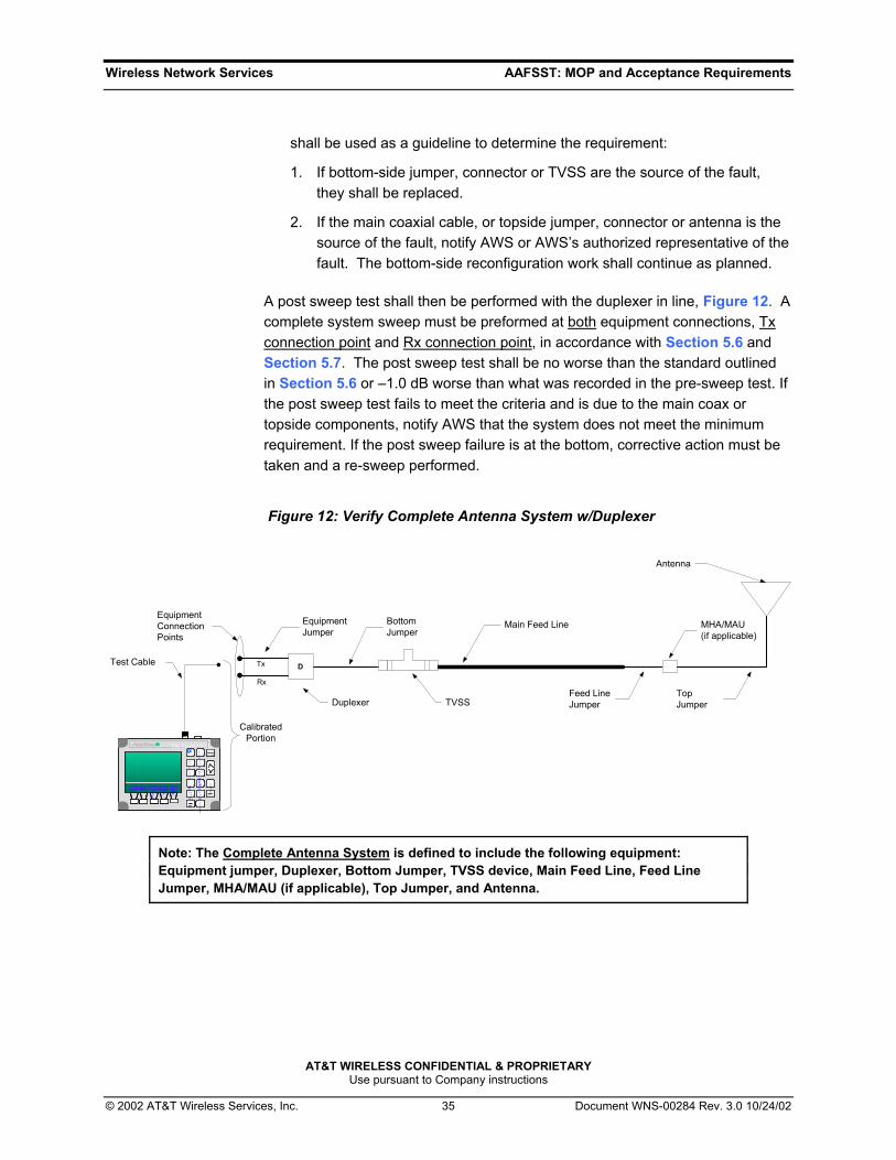
A post sweep test shall then be performed with the duplexer in line, Figure 12. A complete system sweep must be preformed at both equipment connections, Tx connection point and Rx connection point, in accordance with Section 5.6 and Section 5.7. The post sweep test shall be no worse than the standard outlined in Section 5.6 or –1.0 dB worse than what was recorded in the pre-sweep test. If the post sweep test fails to meet the criteria and is due to the main coax or topside components, notify AWS that the system does not meet the minimum requirement. If the post sweep failure is at the bottom, corrective action must be taken and a re-sweep performed.
Figure 12: Verify Complete Antenna System w/Duplexer
Test Cable
BottomJumper
Feed LineJumper
Main Feed Line
Antenna
TVSS
DTx
Rx
Duplexer
EquipmentJumper
EquipmentConnectionPoints
Site Master S331A
STARTCAL
3
RECALLDISPLAY
0
1
MARKER
8
AUTOSCALE
2
SAVESETUP
5RECALLSETUP
6
CAL 4
LIMIT
7
SAVEDISPLAY
9
ONOFF
ESCAPECLEAR
RUNHOLD
ENTER
.
FREQ POWER
DIST SCALE
OPT
Site Master S331ASite Master S331A
STARTCAL
3STARTCAL
3
RECALLDISPLAY
0RECALLDISPLAY
0
11
MARKER
8MARKER
8
AUTOSCALE
2
AUTOSCALE
2
SAVESETUP
5SAVESETUP
5RECALLSETUP
6RECALLSETUP
6
CAL 4CAL 4
LIMIT
7LIMIT
7
SAVEDISPLAY
9SAVEDISPLAY
9
ONOFFONOFFONOFF
ESCAPECLEARESCAPECLEAR
RUNHOLDRUN
HOLD
ENTER
ENTER
.
FREQ POWER
DIST SCALE
OPT
FREQFREQ POWER
POWER
DISTDIST SCALE
SCALE
OPT
OPT
TopJumper
MHA/MAU(if applicable)
CalibratedPortion
Note: The Complete Antenna System is defined to include the following equipment: Equipment jumper, Duplexer, Bottom Jumper, TVSS device, Main Feed Line, Feed Line Jumper, MHA/MAU (if applicable), Top Jumper, and Antenna.

Wireless Network Services AAFSST: MOP and Acceptance Requirements
AT&T WIRELESS CONFIDENTIAL & PROPRIETARY Use pursuant to Company instructions
© 2002 AT&T Wireless Services, Inc. 36 Document WNS-00284 Rev. 3.0 10/24/02
9.2.2 Re-Use Complete Antenna System
Perform a pre-sweep test on the existing antenna system to be used at the appropriate frequency band.
If the pre-sweep test does not meet the pass/fail limits as established in Section 5.6, the tester shall perform a distance to fault test in accordance with Section 5.7.
The distance to fault test results shall then be used to determine the component within the system where the fault exists. The following criteria shall be used as a guideline to determine the site requirements:
1. If bottom-side jumper, connector or TVSS are the source of the fault, they shall be replaced.
2. If top-side jumper, connector, or antenna is the source of the fault, and the pre-sweep test was no worse than the pass/fail limit, proceed with the work and notify AWS or AWS’s authorized representative that the antenna system does not meet the requirements. Tower top work may be required to correct the fault at the direction of AWS.
3. If main coaxial cable is the source of the fault, notify AWS or AWS’s authorized representative of the fault. The main coaxial cable may be replaced, with AWS approval.
Prior to the installation of any new jumper cables each shall be sweep tested in accordance with Section 5.8.
After the work has been completed a post sweep test shall then be performed in accordance with Section 5.6 and Section 5.7.
9.3 Pre-Sweep With Planned Tower Top Work At sites where there is planned tower top work such as antenna replacement, addition of MHA/MAUs or Diplexers, the pre-sweep test shall be performed in accordance with Section 5.6.
The pre-sweep test shall be performed prior to completing any tower top work.

Wireless Network Services AAFSST: MOP and Acceptance Requirements
AT&T WIRELESS CONFIDENTIAL & PROPRIETARY Use pursuant to Company instructions
© 2002 AT&T Wireless Services, Inc. 37 Document WNS-00284 Rev. 3.0 10/24/02
9.3.1 Free Up Complete Antenna System Perform a pre-sweep test on the cable(s) to be duplexed.
If the pre-sweep test does not meet the pass/fail limits as established in Section 5.6, the tester shall perform a distance to fault test in accordance with Section 5.7.
The distance to fault test results shall then be used to determine the component within the system where the fault exists. The following criteria shall be used as a guideline to determine the site requirements:
1. If bottom-side jumper, connector or TVSS, is the source of the fault, it shall be replaced.
2. If top-side jumper, connector, is the source of the fault, replace the defective jumper or connector
3. If the existing TDMA antenna is the source of the fault, proceed with the work and notify AWS or AWS’s authorized representative that the TDMA antenna does not meet the requirement. The TDMA antenna may be replaced to correct the fault at the direction of AWS.
4. If main coaxial cable is the source of the fault, notify AWS or AWS’s authorized representative of the fault. The main coaxial cable may be replaced, with AWS approval.
Prior to the installation of any new jumper cables, duplexers, or diplexers, each of the individual components shall be sweep tested in accordance with Section 5.8 and Section 5.9.
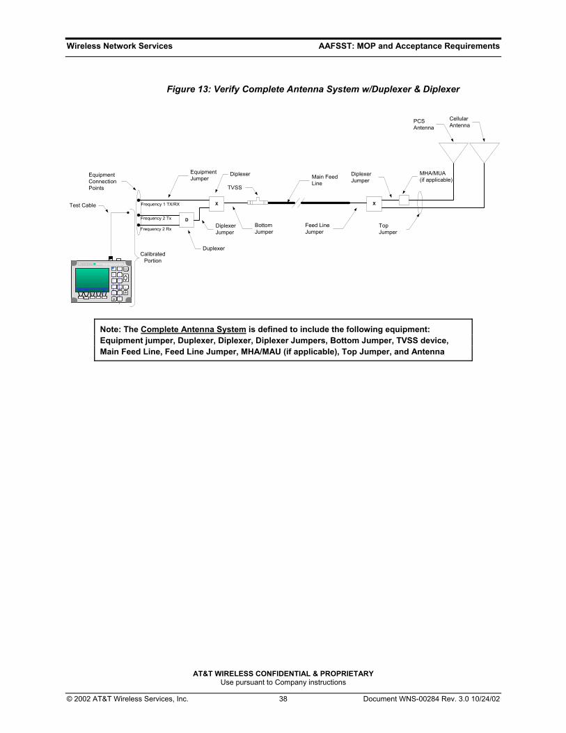
A post sweep test shall be performed with the duplexer and diplexers in line, Figure 13. A complete system sweep must be preformed at all three equipment connections using the appropriate frequencies, Frequency 1 Tx/Rx connection point, Frequency 2 Tx connection point and Frequency 2 Rx connection point, in accordance with Section 5.6 and Section 5.7. The post sweep test shall be no worse than the standard outlined in Section 5.6 or –1.0 dB worse than what was recorded in the pre-sweep test.
Wireless Network Services AAFSST: MOP and Acceptance Requirements
AT&T WIRELESS CONFIDENTIAL & PROPRIETARY Use pursuant to Company instructions
© 2002 AT&T Wireless Services, Inc. 38 Document WNS-00284 Rev. 3.0 10/24/02
Figure 13: Verify Complete Antenna System w/Duplexer & Diplexer
Site Master S331A
STARTCAL
3
RECALLDISPLAY
0
1
MARKER
8
AUTOSCALE
2
SAVESETUP
5RECALLSETUP
6
CAL 4
LIMIT
7
SAVEDISPLAY
9
ONOFF
ESCAPECLEAR
RUNHOLD
ENTER
.
FREQ POWER
DIST SCALE
OPT
Site Master S331ASite Master S331A
STARTCAL
3STARTCAL
3
RECALLDISPLAY
0RECALLDISPLAY
0
11
MARKER
8MARKER
8
AUTOSCALE
2
AUTOSCALE
2
SAVESETUP
5SAVESETUP
5RECALLSETUP
6RECALLSETUP
6
CAL 4CAL 4
LIMIT
7LIMIT
7
SAVEDISPLAY
9SAVEDISPLAY
9
ONOFFONOFFONOFF
ESCAPECLEARESCAPECLEAR
RUNHOLDRUN
HOLD
ENTER
ENTER
.
FREQ POWER
DIST SCALE
OPT
FREQFREQ POWER
POWER
DISTDIST SCALE
SCALE
OPT
OPT
Test Cable
BottomJumper
MHA/MUA(if applicable)
Feed LineJumper
TopJumper
Main FeedLine
PCSAntenna
TVSS
D
XX
DiplexerJumper
CellularAntenna
Frequency 1 TX/RX
Frequency 2 Tx
Duplexer
DiplexerEquipmentConnectionPoints
EquipmentJumper
Frequency 2 Rx DiplexerJumper
CalibratedPortion
Note: The Complete Antenna System is defined to include the following equipment: Equipment jumper, Duplexer, Diplexer, Diplexer Jumpers, Bottom Jumper, TVSS device, Main Feed Line, Feed Line Jumper, MHA/MAU (if applicable), Top Jumper, and Antenna
Wireless Network Services AAFSST: MOP and Acceptance Requirements
AT&T WIRELESS CONFIDENTIAL & PROPRIETARY Use pursuant to Company instructions
© 2002 AT&T Wireless Services, Inc. 39 Document WNS-00284 Rev. 3.0 10/24/02
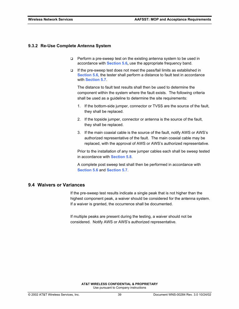
9.3.2 Re-Use Complete Antenna System
Perform a pre-sweep test on the existing antenna system to be used in accordance with Section 5.6, use the appropriate frequency band.
If the pre-sweep test does not meet the pass/fail limits as established in Section 5.6, the tester shall perform a distance to fault test in accordance with Section 5.7.
The distance to fault test results shall then be used to determine the component within the system where the fault exists. The following criteria shall be used as a guideline to determine the site requirements:
1. If the bottom-side jumper, connector or TVSS are the source of the fault, they shall be replaced.
2. If the topside jumper, connector or antenna is the source of the fault, they shall be replaced.
3. If the main coaxial cable is the source of the fault, notify AWS or AWS’s authorized representative of the fault. The main coaxial cable may be replaced, with the approval of AWS or AWS’s authorized representative.
Prior to the installation of any new jumper cables each shall be sweep tested in accordance with Section 5.8.
A complete post sweep test shall then be performed in accordance with Section 5.6 and Section 5.7.
9.4 Waivers or Variances If the pre-sweep test results indicate a single peak that is not higher than the highest component peak, a waiver should be considered for the antenna system. If a waiver is granted, the occurrence shall be documented.
If multiple peaks are present during the testing, a waiver should not be considered. Notify AWS or AWS’s authorized representative.

Wireless Network Services AAFSST: MOP and Acceptance Requirements
AT&T WIRELESS CONFIDENTIAL & PROPRIETARY Use pursuant to Company instructions
© 2002 AT&T Wireless Services, Inc. 40 Document WNS-00284 Rev. 3.0 10/24/02
10. Appendix D: All Test Sceniero Limit References
Table 5: Test Scenieros – Loss Value Limit
Test Type Test Number Return Loss Limit
Frequency Range
Return Loss of Antenna Section 5.1 Table 1 Specific
Return Loss - 50Ω LOAD Section 5.2 -20.0 dB All
DTF - 50Ω LOAD Section 5.3 -25.0 dB All
Return Loss – Short Section 5.4 Appendix E All
Return Loss – Complete Antenna System
without a Duplexer or Diplexer or MHA Section 5.6 -15.5 dB All
Return Loss – Complete Antenna System with a Duplexer or Diplexer or MHA
Section 5.6 -15.5 dB Specific
Wireless Network Services AAFSST: MOP and Acceptance Requirements
AT&T WIRELESS CONFIDENTIAL & PROPRIETARY Use pursuant to Company instructions
© 2002 AT&T Wireless Services, Inc. 41 Document WNS-00284 Rev. 3.0 10/24/02
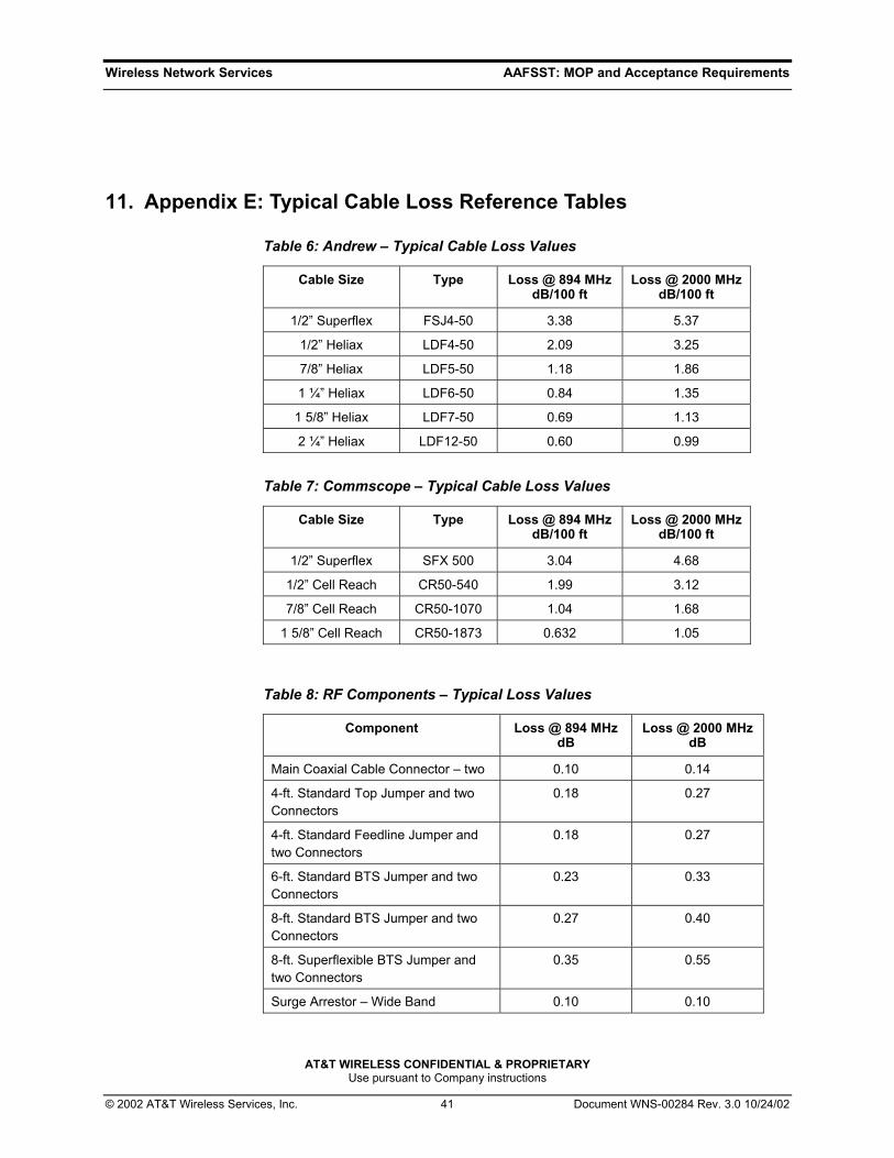
11. Appendix E: Typical Cable Loss Reference Tables
Table 6: Andrew – Typical Cable Loss Values
Cable Size Type Loss @ 894 MHz dB/100 ft
Loss @ 2000 MHz dB/100 ft
1/2” Superflex FSJ4-50 3.38 5.37
1/2” Heliax LDF4-50 2.09 3.25
7/8” Heliax LDF5-50 1.18 1.86
1 ¼” Heliax LDF6-50 0.84 1.35
1 5/8” Heliax LDF7-50 0.69 1.13
2 ¼” Heliax LDF12-50 0.60 0.99
Table 7: Commscope – Typical Cable Loss Values
Cable Size Type Loss @ 894 MHz dB/100 ft
Loss @ 2000 MHz dB/100 ft
1/2” Superflex SFX 500 3.04 4.68
1/2” Cell Reach CR50-540 1.99 3.12
7/8” Cell Reach CR50-1070 1.04 1.68
1 5/8” Cell Reach CR50-1873 0.632 1.05
Table 8: RF Components – Typical Loss Values
Component Loss @ 894 MHz dB
Loss @ 2000 MHz dB
Main Coaxial Cable Connector – two 0.10 0.14
4-ft. Standard Top Jumper and two Connectors
0.18 0.27
4-ft. Standard Feedline Jumper and two Connectors
0.18 0.27
6-ft. Standard BTS Jumper and two Connectors
0.23 0.33
8-ft. Standard BTS Jumper and two Connectors
0.27 0.40
8-ft. Superflexible BTS Jumper and two Connectors
0.35 0.55
Surge Arrestor – Wide Band 0.10 0.10

Wireless Network Services AAFSST: MOP and Acceptance Requirements
AT&T WIRELESS CONFIDENTIAL & PROPRIETARY Use pursuant to Company instructions
© 2002 AT&T Wireless Services, Inc. 42 Document WNS-00284 Rev. 3.0 10/24/02
12. Appendix F: Antenna System Site Submission Forms
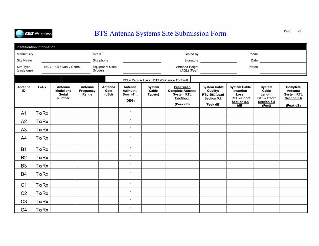
BTS Antenna Systems Site Submission Form
Page ___ of ___
Identification Information
Market/City Site ID Tested by Phone
Site Name Site phone Signature Date
Site Type (circle one)
850 / 1900 / Dual / Comb. Equipment Used (Model)
Antenna Height (AGL) (Feet)
Notes
RTL= Return Loss : DTF=Distance To Fault
Antenna ID
Tx/Rx Antenna Model and
Serial Number
Antenna Frequency
Range
Antenna Gain (dBd)
Antenna Azimuth / Down-Tilt
(DEG)
System Cable
Type(s)
Pre-Sweep Complete Antenna
System RTL Section 9
(Peak dB)
System Cable Quality:
RTL-50Ω Load Section 5.2
(Peak dB)
System Cable Insertion
Loss: RTL – Short Section 5.4
(dB)
System Cable
Length: DTF – Short Section 5.5
(Feet)
Complete Antenna
System RTL Section 5.6
(Peak dB)
A1 Tx/Rx /
A2 Tx/Rx /
A3 Tx/Rx /
A4 Tx/Rx /
B1 Tx/Rx /
B2 Tx/Rx /
B3 Tx/Rx /
B4 Tx/Rx /
C1 Tx/Rx /
C2 Tx/Rx /
C3 Tx/Rx /
C4 Tx/Rx /
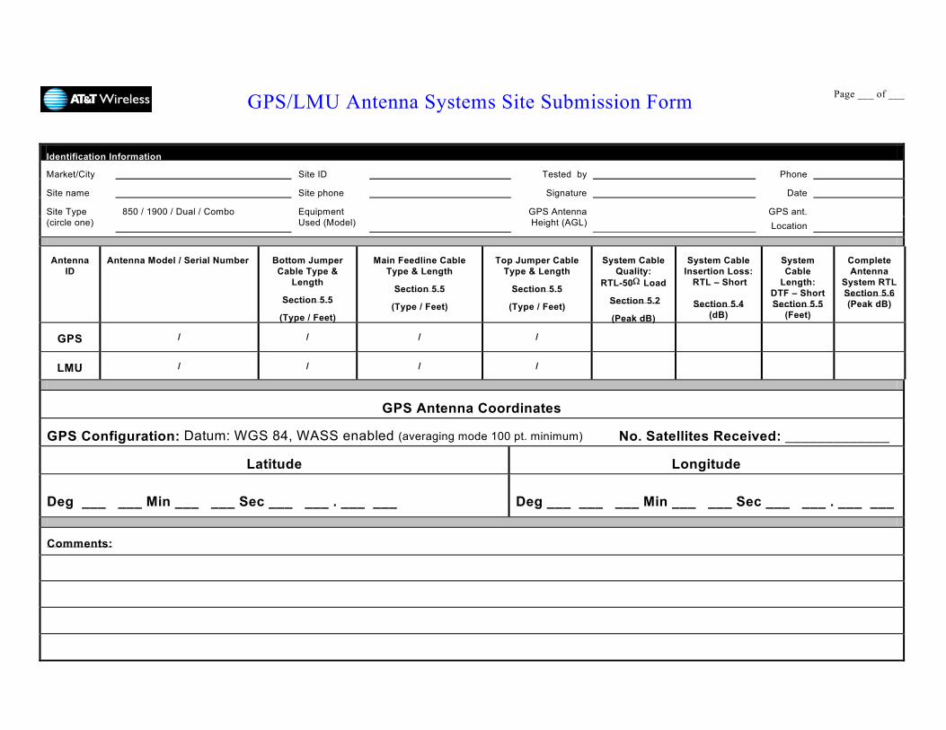
GPS/LMU Antenna Systems Site Submission Form
Page ___ of ___
Identification Information
Market/City Site ID Tested by Phone
Site name Site phone Signature Date
Site Type (circle one)
850 / 1900 / Dual / Combo Equipment Used (Model)
GPS Antenna Height (AGL)
GPS ant. Location
Antenna ID
Antenna Model / Serial Number Bottom Jumper Cable Type &
Length
Section 5.5
(Type / Feet)
Main Feedline Cable Type & Length
Section 5.5
(Type / Feet)
Top Jumper Cable Type & Length
Section 5.5
(Type / Feet)
System Cable Quality:
RTL-50Ω Load
Section 5.2
(Peak dB)
System Cable Insertion Loss:
RTL – Short
Section 5.4 (dB)
System Cable
Length: DTF – Short Section 5.5
(Feet)
Complete Antenna
System RTL Section 5.6 (Peak dB)
GPS / / / /
LMU / / / /
GPS Antenna Coordinates
GPS Configuration: Datum: WGS 84, WASS enabled (averaging mode 100 pt. minimum) No. Satellites Received: _____________
Latitude Longitude
Deg ___ ___ Min ___ ___ Sec ___ ___ . ___ ___
Deg ___ ___ ___ Min ___ ___ Sec ___ ___ . ___ ___
Comments:

AOA Antenna Systems Site Submission Form
Page ___ of ___
Identification Information
Market/City Site ID Tested by Phone
Site Name Site phone Signature Date
Site Type (circle one)
850 / 1900 Equipment Used (Model)
AOA Antenna Height (AGL) (Ft)
Notes
AOA
Antenna ID Port
Port Type
AOA Antenna Model and
Serial Number
Antenna Frequency Range
AOA Antenna Azimuth and
Down-Tilt
(DEG)
System Cable Quality: RTL-50Ω
Load
Section 5.2
(Peak dB)
System Cable Insertion Loss:
RTL – Short
Section 5.4
(dB)
System Cable Length:
DTF - Short Section 5.5
(Feet)
Complete Antenna System
RTL Section 5.6
(Peak dB)
A1 Rx
A2 Rx
A3 Rx
A4 Rx
A5 CAL
B1 Rx
B2 Rx
B3 Rx
B4 Rx
B5 CAL
C1 Rx
C2 Rx
C3 Rx
C4 Rx
C5 CAL