WLAN Express Setup and Best Practices Deployment · PDF fileWLAN Express Setup and Best...
27
WLAN Express Setup and Best Practices Deployment Guide WLAN Express Setup and Best Practices Deployment Guide 2 Introduction 2 Supported Controllers and APs 4 Installing WLC 5 RF Profiles Configurations 16 Monitoring Dashboards 17 Best Practices Configurations 20
Transcript of WLAN Express Setup and Best Practices Deployment · PDF fileWLAN Express Setup and Best...

WLAN Express Setup and Best Practices Deployment Guide
WLAN Express Setup and Best Practices Deployment Guide 2
Introduction 2
Supported Controllers and APs 4
Installing WLC 5
RF Profiles Configurations 16
Monitoring Dashboards 17
Best Practices Configurations 20

Revised: April 29, 2015,
WLAN Express Setup and Best Practices Deployment Guide
IntroductionIn release 8.1 of UnifiedWLC software, Cisco introduces a new simplified first time out of box installation and configuration interfacefor 2500, 5500, 7500, and 8500 wireless series controllers. The goal of this deployment guide is to provide a set of instructions tohelp easily setup a WLC to operate in a small, medium, or large network wireless environment, where access point(s) can join andtogether as a simple solution and provide various services, such as corporate employee or guest wireless access on the network.
With thisWLAN Express setup software release, there is a new GUI simplified controller express setup in addition to two legacyways to configure the Unified Wireless LAN Controller:
• Traditional command line interface (CLI) via serial console
• Updated method using network connection directly to the WLC GUI setup wizard
This guide provides instruction only for using the WLAN Express GUI setup wizard. Note that the WLAN Express Setup can beused only for the first time in out of box installations or when controller configuration is reset to factory defaults.
Configuring WLCThe general steps to configure the WLC are as follows:
2

Procedure
Step 1 Complete the configuration checklist.Step 2 Unpack, connect, and power on the WLC.Step 3 Connect a client machine to Service Port of the WLC with an Ethernet cable.Step 4 Open a client web browser to access the WLC startup GUI.Step 5 Enter the settings from the completed configuration checklist.Step 6 Disconnect the WLC from client machine and connect to the network switch.Step 7 Connect access point(s) to the network switch.
Access points join the WLC, and the configured wireless network become available.Step 8 Connect wireless client(s) to the available network.
Configuration Checklist
The following checklist helps you to make the installation process easier, while using the GUI wizard to configure the WLC. Whilemost of the information from the list is mandatory, there is some information that is optional (*). Take a moment to fill out:
• Network switch requirement (see above reference for switch configuration example):
◦WLC switch port number assigned
◦WLC assigned switch port
◦Is the switch port configured as trunk?
◦Is there a management VLAN? Management VLAN ID
◦Is there a guest VLAN? Guest VLAN ID
•WLC Settings:
◦New admin account name
◦Admin account password
◦System name for the WLC
◦The current time zone
◦Is there a NTP server available? NTP server IP address
◦WLC Management Interface:
◦IP address
◦Subnet mask
◦Default gateway
◦Management VLAN ID
3

• Corporate Wireless Network
• Corporate wireless name/SSID
• Is a RADIUS server required?
• Security authentication option to select:
◦WPA/WPA2 Personal
◦Corporate pass phrase (PSK)
◦WPA/WPA2 Enterprise)
◦RADIUS server IP address and shared secret
◦Is a DHCP server known? DHCP server IP address
• Guest Wireless Network - optional:
◦Guest wireless name/SSID
◦Is a password required for guest?
◦Guest pass phrase (PSK)
◦Guest VLAN id (use id)
◦Guest networking:
◦IP address
◦Subnet mask
◦Default gateway
• Advanced option—Configure RF Parameters for Client Density as Low, Medium, or High.
Supported Controllers and APsThe following controllers and APs are supported:
• Cisco 2500, 5500, 7500, 8500 series wireless LAN controller.
• Cisco WLC 8.1 supported APs; see 8.1 Release Notes for the list of supported APs.
4

Installing WLC
Procedure
Step 1 Connect a PC laptop's wired Ethernet port directly to Service Port of the WLC ( see the following figure for Service Portlocation). The port LEDs blink to indicate that both machines are properly connected.
Figure 1: Service Port Location
Figure 2: Sample of Initial Wireless Network Configuration; IP Addresses Used as an Example
It may take several minutes for the WLC to fully power on to make the GUI available to the PC. Do not autoconfigure controller.
Note
5

The LEDs on the front panel provide system status:
• The system is not ready – LEDs is OFF
• The controller is ready – LED is solid green
Step 2 Configure DHCP option on the Laptop that you are connecting to the Service port. This assigns an IP address to yourLaptop from the Controller service port 192.168.1.X or you can assign a static IP address 192.168.1.X to your Laptop toaccess the WLC GUI; both options are supported.The following figure shows an example of the Mac Laptop getting an IP address from the DHCP service port for the initialconfiguration of the controller.
6

The following figure shows an example of network settings on Windows PC (Start > Run > CMD > ipconfig).
Step 3 Upon confirming that there is an IP address of 192.168.1.x assigned to your computer, open a web browser (preferablyChrome and Safari) and open the URL: http://192.168.1.1.The following screen appears in your browser.
7
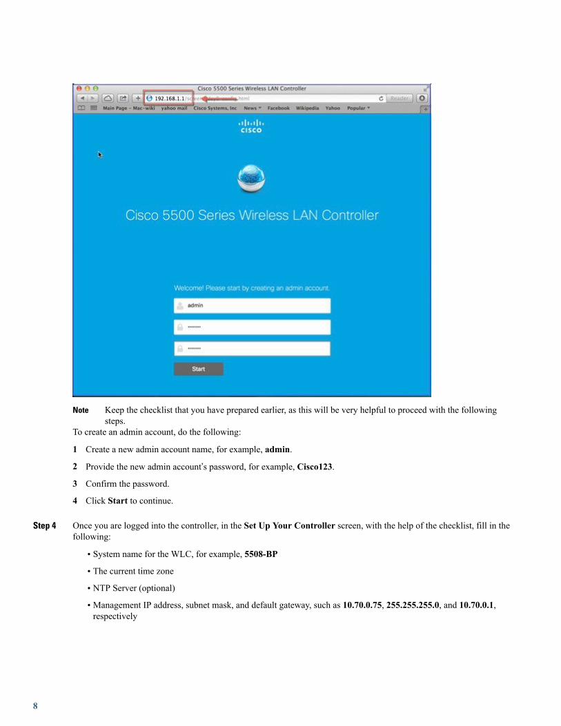
Keep the checklist that you have prepared earlier, as this will be very helpful to proceed with the followingsteps.
Note
To create an admin account, do the following:
1 Create a new admin account name, for example, admin.
2 Provide the new admin account’s password, for example, Cisco123.
3 Confirm the password.
4 Click Start to continue.
Step 4 Once you are logged into the controller, in the Set Up Your Controller screen, with the help of the checklist, fill in thefollowing:
• System name for the WLC, for example, 5508-BP
• The current time zone
• NTP Server (optional)
• Management IP address, subnet mask, and default gateway, such as 10.70.0.75, 255.255.255.0, and 10.70.0.1,respectively
8

• Management VLAN ID (see checklist), if left unchanged (or 0), then the network switch port must be configuredwith a native VLAN X0
The wizard will attempt to import the clock information (date and time) from the computer via JavaScript. It ishighly recommended that you confirm this before continuing. Access points rely on correct clock settings to beable to join the WLC.
Figure 3: Sample configuration for 5508
Note
Step 5 In the Create Your Wireless Networks screen, in the Employee Network area, with the help of the checklist, fill in thefollowing:
• Network name/SSID, for example, cisco-bp
• Security, for example,WPA/WPA2 Personal
9

WPA/WPA2 Personal—Provide a pass phrase (PSK /for example, Cisco123 and confirm the pass phrase)•
• Provide the DHCP server address (for example, 10.70.0.1). If left empty, the DHCP processing is bridged to themanagement interface.
Figure 4: Example of an Employee Network Configured with WPA/WPA2 Personal Using PSK (pre-shared key / pass phrase) for5508-bp
Step 6 (Optional) In the Create Your Wireless Networks screen, in the Guest Network area, with the help of the checklist, fillin the following:
• Network name/SSID, for example, bp-guest
• Security, for example,Web Consent
10
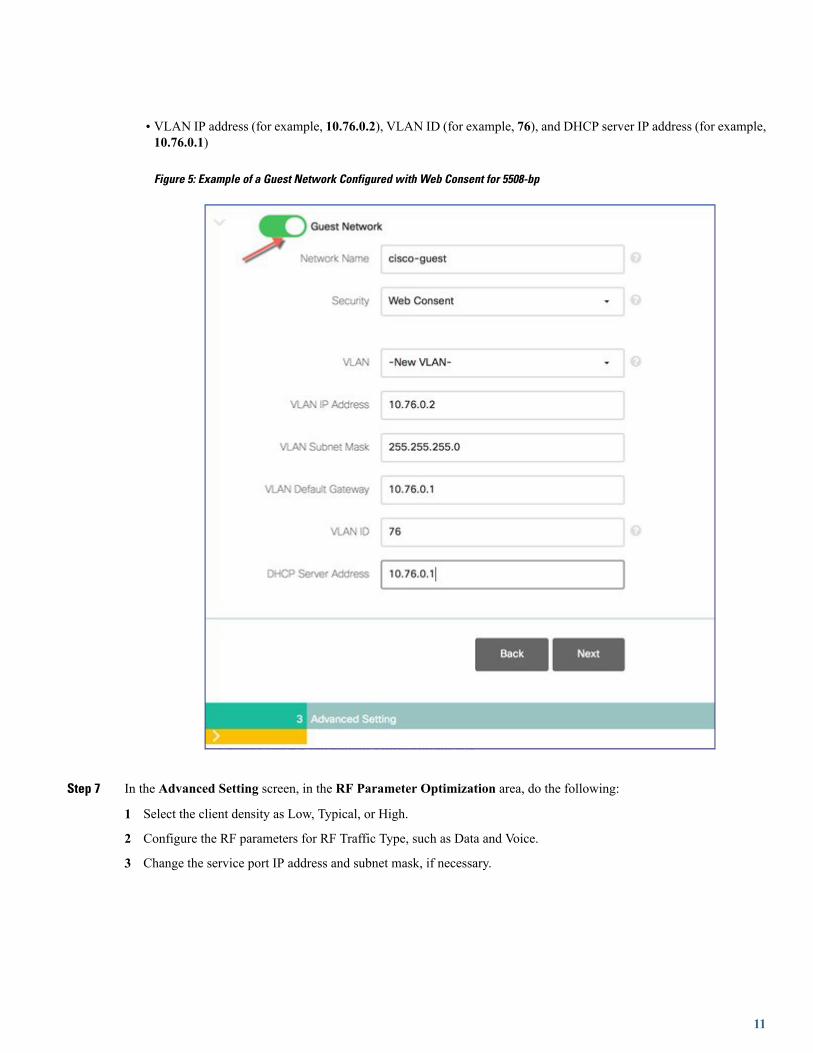
• VLAN IP address (for example, 10.76.0.2), VLAN ID (for example, 76), and DHCP server IP address (for example,10.76.0.1)
Figure 5: Example of a Guest Network Configured with Web Consent for 5508-bp
Step 7 In the Advanced Setting screen, in the RF Parameter Optimization area, do the following:
1 Select the client density as Low, Typical, or High.
2 Configure the RF parameters for RF Traffic Type, such as Data and Voice.
3 Change the service port IP address and subnet mask, if necessary.
11
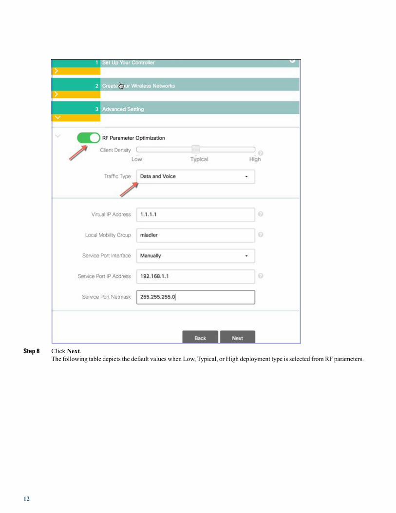
Step 8 Click Next.The following table depicts the default values when Low, Typical, or High deployment type is selected from RF parameters.
12
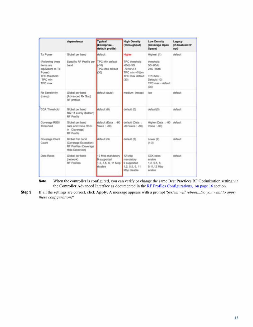
When the controller is configured, you can verify or change the same Best Practices RF Optimization setting viathe Controller Advanced Interface as documented in the RF Profiles Configurations, on page 16 section.
Note
Step 9 If all the settings are correct, click Apply. A message appears with a prompt 'System will reboot...Do you want to applythese configuration?'
13

14

Step 10 Click OK to apply final settings.The WLC reboots automatically. A confirmation page will show that 'The controller has been fully configured and willnow restart'. If this message does not appear, do the following:
1 Disconnect your computer from the WLC service port and connect it to Switch port.
2 Connect the WLC port 1 to the switch configured trunk port.
3 Connect access points to the switch if not already connected.
15
4 Wait until the access points join the WLC.
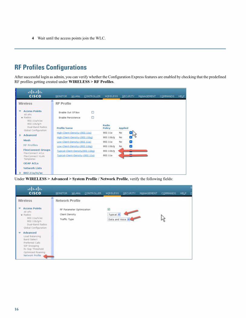
RF Profiles ConfigurationsAfter successful login as admin, you can verify whether the Configuration Express features are enabled by checking that the predefinedRF profiles getting created underWIRELESS > RF Profiles.
UnderWIRELESS > Advanced > System Profile / Network Profile, verify the following fields:
16

It is recommended to use RF and Network profiles configuration even if the WLAN Express setup wasnot used initially or if the controller was upgraded from the software prior to release 8.1.
Note
Monitoring DashboardsIn release 8.1 of the Wireless LAN Controller, a new Dashboard interface is introduced when initiating a Web UI connectivity to thecontroller. Previously, when connecting to the controller Management Interface, the user was able to see a summary of the controllermonitor interface. In the web browser, enter the IP address of the management interface as previously configured and enter the admincredentials that were created earlier, that is, Login Name: admin and password Cisco123.
In release 8.1, a new interface is added to present the system administrator with additional practical at glance information. This newMonitoring interface contains several Dashboards and monitoring options. Upon connecting to the controller management interface,the Network Summary page is first displayed. The administrator can spend some time to explore this page, and then log into theWLC to access web UI and dashboard.
17

As shown in the left pane, theMonitoring interface allows you to chooseNetwork Summary,Wireless Dashboard, orBest Practices.Network Summary has additional submenus to monitor the access points and clients.
The following is a screenshot from the Access Points submenu, where the monitoring page displays information about 2.4 GHz and5 GHz access points. The information gives the administrator a Bird’s Eye view on the access point's valuable details.
18

While choosing AP Performance underWireless Dashboard, charts are displayed about various AP performance statistics, suchas Channel Utilization - Top APs, Interference - Top APs, Client Load - Top APs, and Coverage Bottom APs.
Few additional icons are available in the upper right corner of the dashboard as in the following figure.
19

Click icon to view the additional options.
Click to view the legacy controller interface as shown in the following figure.
The icon takes you back to the Dashboard Monitoring interface.Note
Click Home to view the information about:
• Network Summary
• Access Points
• Clients
•Wireless Dashboard
• AP Performance
• Client Performance
• Best Practices
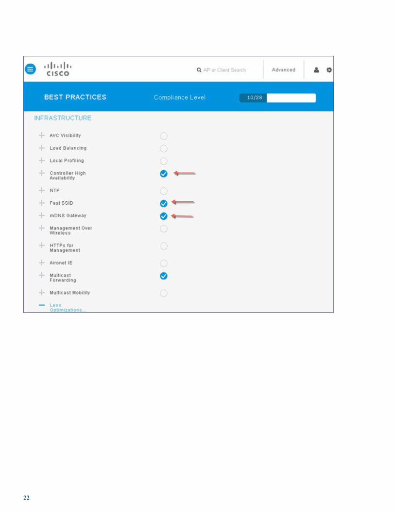
Best Practices ConfigurationsClick Best Practices to view the information about:
• Infrastructure
20

• Security
• RF Management
Few best practices parameters are configured by default as recommended by Cisco wireless experts. The level of compliance 10/28represents this setting.
21
22

You can click the + icon to select a recommended best practice parameter, read an expert recommendation, and click Fix it Now orlater reverse the BP configuration option by clicking Restore Default. Following is an example of BP Local Profiling configuration.
23

If you click Learn More, the Monitoring interface displays the Cisco Best Practices Configuration and Deployment Guide as in thefollowing figure.
The following table shows all best practices recommendations in release 8.1.
8.1Feature
Yes( 2504 only)AVC Visibility
YesmDNS Snooping
YesNew MDNS Profile for printer, http
24

8.1Feature
YesLocal Profiling
YesBand Select
YesDHCP Proxy
YesSecure Web access
Yes (configurable)Virtual IP 192.0.2.1
YesRRM-DCA Auto
YesRRM-TPC Auto
YesCleanAir Enabled
YesEDRRM Enabled
YesChannel Width 40 MHz
YesAironet IE Disabled
NoManagement over Wireless
Yes (network profile)2.4 Low Data Rates Disabled
Yes (network profile)Load Balancing
YesRogue Threshold Enabled
YesClient Exclusion Enabled
YesFastSSID Enabled*
YesInfra MFP
YesMulticast Forwarding Mode
YesSNMPv3 (delete default)
YesMobility Name
YesRF Group same as Mobility Name
YesDHCP Required on Guest WLAN
Yes5 GHz Channel Bonding*
25

© 2015 Cisco Systems, Inc. All rights reserved.

Europe HeadquartersAsia Pacific HeadquartersAmericas HeadquartersCisco Systems International BVAmsterdam, The Netherlands
Cisco Systems (USA) Pte. Ltd.Singapore
Cisco Systems, Inc.San Jose, CA 95134-1706USA
Cisco has more than 200 offices worldwide. Addresses, phone numbers, and fax numbers are listed on theCisco Website at www.cisco.com/go/offices.