ERLN/WLA 2012 WLA Security Summit Nashville, Tennessee March 23, 2012 1.

WLA-500AP
WISP Client Router Mode
User’s Manual

Copyright Statement
No part of this publication may be reproduced, stored in a retrieval system, or transmitted in any form or by any means, whether electronic, mechanical, photocopying, recording or oth-erwise without the prior writing of the publisher. Windows 95/98/Me and Windows 2000 are trademarks of Microsoft Corp. Pentium is trademark of Intel. All copyright is reserved.
AirLive WLA-5000AP WISP+Client Router Mode 1

AirLive WLA-5000AP WISP+Client Router Mode 2
TABLE OF CONTENT
INTRODUCING THE WISP CLIENT ROUTER MODE ...............................................................................................................................3 OVERVIEW OF THE WLA-5000AP.................................................................................................................................................................4 WISP CLIENT ROUTER MODE APPLICATIONS..............................................................................................................................................4
Accessing the Internet .................................................................................................................................................................................4 Accessing Servers from the Public Network ...............................................................................................................................................5
A SECURITY OVERVIEW .................................................................................................................................................................................5 WLA-5000AP FEATURES .............................................................................................................................................................................5 SETTING UP THE DEVICE ................................................................................................................................................................................6
INSTALLING THE WLA-5000AP.................................................................................................................................................................7 WHAT’S IN THE BOX?......................................................................................................................................................................................7 A PHYSICAL LOOK AT THE BACK PANEL .........................................................................................................................................................8 A PHYSICAL LOOK AT THE FRONT PANEL .......................................................................................................................................................9 CONNECTING THE CABLES ...........................................................................................................................................................................10 HIGH LEVEL CONFIGURATION STEPS REQUIRED FOR THE WLA-5000AP ..............................................................................................10 SETTING UP A WINDOWS PC OR WIRELESS CLIENT AS DHCP CLIENTS...................................................................................................10 CONFIGURING A PC RUNNING MS-WINDOWS 95/98/ME: .........................................................................................................................11 CONFIGURING A PC RUNNING MS-WINDOWS XP/2000: ..........................................................................................................................11 CONFIRMING YOUR PC’S IP CONFIGURATION:...........................................................................................................................................11 CONNECTING MORE DEVICES THROUGH A HUB TO THE WLA-5000AP ................................................................................................12
BASIC CONFIGURATION OF THE WLA-5000AP .................................................................................................................................13 LOGGING ON .................................................................................................................................................................................................14 SETUP WIZARD .............................................................................................................................................................................................14
Set up your Local Time Zone and Date/Time ...........................................................................................................................................15 Configure the ISP profile ..........................................................................................................................................................................15 Device IP Settings .....................................................................................................................................................................................19 Configure Your Wireless LAN Connection ...............................................................................................................................................20 Finish Setup Wizard and Save Your Settings............................................................................................................................................23
ADVANCED SETTINGS ...............................................................................................................................................................................25 PASSWORD SETTINGS ..................................................................................................................................................................................26 SYSTEM MANAGEMENT ................................................................................................................................................................................27 SNMP SETTINGS..........................................................................................................................................................................................29 DHCP SERVER SETTINGS ...........................................................................................................................................................................31 MULTIPLE DMZ .............................................................................................................................................................................................33 VIRTUAL SERVER SETTINGS ........................................................................................................................................................................34 SPECIAL APPLICATIONS...............................................................................................................................................................................35 IP FILTERING SETTINGS ...............................................................................................................................................................................36 IP ROUTING SETTINGS .................................................................................................................................................................................38 WIRELESS SETTINGS ....................................................................................................................................................................................39 DYNAMIC DNS SETTINGS ............................................................................................................................................................................40
MANAGING YOUR WLA-5000AP..............................................................................................................................................................42 HOW TO VIEW THE DEVICE STATUS ............................................................................................................................................................42 HOW TO VIEW THE SYSTEM LOG.................................................................................................................................................................43 DHCP CLIENT TABLE ...................................................................................................................................................................................44 BRIDGE TABLE ..............................................................................................................................................................................................44 RADIO TABLE.................................................................................................................................................................................................45 UPGRADING FIRMWARE................................................................................................................................................................................46 HOW TO SAVE OR RESTORE CONFIGURATION CHANGES .........................................................................................................................48 HOW TO RESTORE THE SYSTEM SETTINGS TO THE FACTORY DEFAULTS ...............................................................................................49 HOW TO REBOOT YOUR WLA-5000AP .....................................................................................................................................................50 WHAT IF YOU FORGOT THE PASSWORD?...................................................................................................................................................51
SPECIFICATION ............................................................................................................................................................................................52

I
Tvc
Chapter
1 ntroducing the WISP Client Router Mode
his manual gives a basic introduction to WISP Client Router Mode. It pro-ides information to configure the WLA-5000AP to operate in common appli-ations such as connecting to the Internet.
We’ll describe how to use your web browser to configure the WLA-5000AP and to perform various management functions, e.g. upgrading the software, or viewing the system log, a task that can be useful in ongoing operations.
This manual consists of the following chapters and appendixes:
Chapter One, Introduction, summarizes features and capabilities of the WLA-5000AP.
Chapter Two, Installing the WLA-5000AP, gives steps you should follow to install the WLA-5000AP and configure your PCs.
Chapter Three, Configuring the WLA-5000AP, describes how to log in to the Web Manager, the browser screen, and steps needed to configure your WLA-5000AP for specific applications. It gives easy-to-follow instructions for quick Internet access and provides a guide to basic WLA-5000AP con-figuration.
Chapter Four, Advanced Configuration, provides information on advanced router configuration.
Chapter Five, Managing your WLA-5000AP, explains other management features of the WLA-5000AP.
3

Overview of the WLA-5000AP
The WISP Client Router mode that sits between your local Ethernet network and a remote network (e.g., the Internet). The WLA-5000AP contains a 10/100Mbps Ethernet switch for connection to PCs on your local wired network, and two wireless interfaces for connection to your local wireless network: one supports 802.11a, another can be configured to support either both 802.11b and 802.11g or 802.11g only (both radios support a data rate of up to 54 Mbps).
Data comes into the WLA-5000AP from the local wired and wireless LAN and then is “routed” to the Internet, and vice versa.
WISP Client Router mode Applications
A C C E S S I N G T H E I N T E R N E T
The most common use of the WISP Client Router mode is to provide shared Internet access to allow everyone on your LAN to surf the web and send/receive emails or files. The WISP Client Router mode can automatically acquire a public IP address when connecting to the Internet. In turn, it will
AirLive WLA-5000AP WISP+Client Router Mode 4
automatically assign IP addresses to PCs (requesting DHCP client devices) on your LAN - you don’t have to apply for and assign IP addresses to PCs on your network.
A C C E S S I N G S E R V E R S F R O M T H E P U B L I C N E T W O R K
If you want special servers to be accessible to remote users across the Internet (e.g., an e-mail server, an FTP server, or a web server), you can configure the WLA-5000AP to proxy the service using its (public) IP address. It means a remote user can access the server by using the WLA-5000AP’s IP address. Upon receiving a request, the WLA-5000AP will re-direct the request to the actual server on your local network.
A Security Overview
More and more people are concerned about protecting your local network from the Internet. The WLA-5000AP provides several ways to keep your network secure:
Devices on your wired or wireless network are assigned private IP addresses; therefore remote users from the Internet cannot see nor access them.
The WLA-5000AP implements IP packet filtering with SPI (Stateful Packet Inspection) capabili-ties, which you can use to selectively filter (discard) packets to/from the Internet.
You can selectively restrict management from remote devices.
To address the growing security concern in a wireless LAN environment, different levels of security can also be enabled in the WLA-5000AP, including:
To disable SSID broadcast so to restrict association to only client stations that are already pre-configured with correct SSIDs
To enable WEP (Wireless Encryption Protocol) encryption to implement privacy of your data To enable WPA (WiFi Protected Access) to assure authorized access as well as to implement pri-
vacy of your data. WPA comes with PSK (Pre-Shared Key) for SOHO users.
WLA-5000AP Features
High performance 11 Mbps (802.11b) or 54Mbps (802.11a/g) data rate Wi-Fi, WPA certificated interoperability Web-based, SNMP v1/v2, Telnet management WPA with Pre-Shared Key Support WPA with TKIP Support WPA with Advanced Encryption Standard (AES) support 152-bit WEP support (Atheros Proprietary) S/W (station/receiver based) DMZ support VPN pass through support Advanced NAT/Firewall features Special applications support including MSN Messenger6.0, Netmeeting… etc 802.1d Spanning Tree Protocol support
RoHS complied
5

Setting Up the device
A local PC on either the wired or wireless LAN network can manage the WLA-5000AP. To do this, the WLA-5000AP must have an IP address, which can be statically configured, or is dynamically ob-tained from a DHCP server on the LAN.
AirLive WLA-5000AP WISP+Client Router Mode 6

I
Tstfo
nstalling the WLA-5000AP
his section describes the installation procedure for your WLA-5000AP. It arts with a summary of the content of the package you have purchased, llowed by steps of how to connect and power up your WLA-5000AP.
Finally, it describes how to configure a Windows PC to communicate with your WLA-5000AP.
Chapter
2 What’s in the Box?
The WLA-5000AP package comes with the following items:
One WLA-5000AP
One 5V DC/2A power adapter with a barrel connector
One CD contains WLA-5000AP User’ Guide
7

A physical look at the back panel
The following illustration shows the rear panel of WLA-5000AP.
(1) 1 RJ-45 10/100 Switch connectors for connecting to PCs and workstations or connecting external Ethernet hub, or switch with auto-sensing.
(2) 1 DC 5V/2A power connector for connecting through a DC power adapter (included as part of the product) to the wall power outlet.
(3) 1 Reset button to restore the device back to the factory settings.
AirLive WLA-5000AP WISP+Client Router Mode 8

A physical look at the front panel
The LEDs on the front of the WLA-5000AP reflect the operational status of the unit.
WLA-5000AP LED Description
Label LAN WAN 11g (WLAN) 11a (WLAN) Power
Steady Green Link is active Link is active Link is active Link is active System boot-up OK
OFF No LAN connec-tion No connection Radio off Radio off No Power
Flashing Green XMT/RCV Data XMT/RCV Data XMT/RCV Data XMT/RCV Data Under boot-up
9
Connecting the Cables
Follow these steps to install your WLA-5000AP:
Step 1. Connect ADSL/Cable modem to the Wireless Router WAN port using CAT5 UTP LAN cable.
Step 2. Connect a PC/Workstation to one of the LAN ports of the Wireless Router.
Step 3. Connect one end of the DC adapter to the Wireless Router and plug the other end into an electrical outlet.
High Level Configuration Steps Required for the WLA-5000AP
This section describes configuration required for the WLA-5000AP before it can work properly in your network.
Normally, devices on both LANs (except for servers) are configured to obtain their IP addresses automatically. Depending on whether there is a separate DHCP server available in your LAN envi-ronment network, thus to determine if you need to enable the built-in DHCP server in the Wireless Router. The following configuration step assumes that the router’s built-in DHCPS will be used.
Additionally, since you need to perform various configuration changes to the WLA-5000AP, including the SSID, Channel number, the WEP key, etc., it is necessary to associate a fixed IP address with the WLA-5000AP, which is why the WLA-5000AP will be shipped with a factory default private IP ad-dress of 192.168.1.1 (and a network mask of 255.255.255.0).
Setting up a Windows PC or wireless client as DHCP clients
The following will give detailed steps of how to configure a PC or a wireless client to “obtain IP ad-dresses automatically”. For other types of configuration, please refer to the corresponding user manual.
For the case of using a LAN attached PC, the PC must have an Ethernet interface installed properly, be connected to the WLA-5000AP either directly or through an external LAN switch, and have TCP/IP installed and configured to obtain an IP address automatically from a DHCP server in the network.
AirLive WLA-5000AP WISP+Client Router Mode 10

For the case of using a wireless client, the client must also have a wireless interface installed properly, be physically within the radio range of the WLA-5000AP, and have TCP/IP installed and configured to obtain an IP address automatically from a DHCP server in the network.
Configuring a PC running MS-Windows 95/98/Me:
1. Click the Start Button, and select Settings. 2. Click the Control Panel. The Win95/98/Me Control Panel will appear. 3. Open the Network setup window by double-clicking the Network icon. 4. Check your list of Network items. If TCP/IP is already installed, proceed to step 5. Otherwise:
(You may need your Windows CD to complete the installation of TCP/IP.) Click the ADD button. In the Network Component Type dialog box, select Protocol. In the Select Network Protocol dialog box, select Microsoft. In the Network Protocols area of the same dialog box, select TCP/IP and click OK.
5. With TCP/IP installed, select TCP/IP from the list of Network Components. 6. In the TCP/IP window, check each of the tabs and verify the following settings:
Bindings: Select Client for Microsoft Networks and Files and printer sharing for Microsoft Networks
Gateway: All fields are blank. DNS Configuration: Select Disable DNS. WINS Configuration: Select Use DHCP for WINS Resolution. IP address: Select the Obtain IP address automatically radio button.
7. Reboot the PC.
Configuring a PC running MS-Windows XP/2000:
1. Click the Start button, and choose Control Panel (in Classic View). 2. In the Control Panel, double-click Network Connections. 3. Double-click Local Area Connection. 4. In the LAN Area Connection Status window, select Internet Protocol (TCP/IP) and click Proper-
ties. 5. Select the Obtain an IP address automatically and the Obtain DNS server address automatically
radio buttons. 6. Click OK to finish the configuration.
Confirming your PC’s IP Configuration:
There are two tools useful for finding out a computer's IP address and default gateway:
WINIPCFG (for Windows 95/98/Me) Select the Start button, and choose Run. Type winipcfg, and a window will appear listing the IP configuration. You can also type winipcfg in the MS-DOS prompt.
11

The procedure required to set a static IP address is not too much different from the procedure re-quired to set to “obtain IP addresses dynamically” - except that instead of selecting “obtain IP ad-dresses dynamically, you should specify the IP address explicitly.
Connecting More Devices Through A Hub To The WLA-5000AP
The Wireless Router provides four LAN ports to allow up to four PCs or Workstations to be connected to it directly. If you want to connect more devices, you can connect an external hub or switch to any of the LAN ports using a LAN cable.
AirLive WLA-5000AP WISP+Client Router Mode 12

Basic Configuration of the WLA-5000AP
This section contains basic configuration procedure for the WLA-5000AP. It also describes how to set up the WISP Client Router mode for Internet Ac-cess operation, and how to set up the LAN configuration.
Chapter
3 The WLA-5000AP is designed so that all basic configuration may be easily invoked through the a standard Web browser such as Internet Explorer. Currently only the Internet Explorer 6.0 (or above) is supported.
To access the WLA-5000AP’s management interface for the first time, enter the default IP ad-dress of the WLA-5000AP in your Web browser http://192.168.1.1/.
Note: The IP address of your PC must be in the same IP subnet as the WLA-5000AP. It is preferred that you con-figure the PC to obtain an IP address automatically from the WLA-5000AP.
The Home Page of the WLA-5000AP screen will appear, with its main menu displayed on the screen, showing the following top-level choices: Setup Wizard, Device Status, System Tools, Ad-vanced Settings, and Help. Selecting any will allow you to navigate to other configuration menus.
13

Logging On
When you attempt to access a configuration screen from the browser menu, an administrator login screen will appear, prompting you to enter your password to log on. Once you are logged in, you will not be asked to log in again unless your “session” expires such as due to inactivity timeout.
If you are logging in for the first time after you received your WLA-5000AP you should use the factory default password, “airlive” to log in. (You should change it as soon as after you log in.)
Characters you type (as your password) will be echoed back as a string of asterisks (“*”) for security reasons. After you enter the password, clicking the LOG ON button will begin the password verifica-tion process and, if successful, your configuration session can begin.
Note: Should there be no settings or access on the web management screen, system will logout auto-matically in 10 minutes.
Setup Wizard
The Setup Wizard will guide you through a series of configuration screens to set up the basic configu-ration of your WLA-5000AP At the end of the Setup Wizard screens, you should press the “FINISH” button, and all your configuration modifications will take effect.
AirLive WLA-5000AP WISP+Client Router Mode 14

S E T U P Y O U R L O C A L T I M E Z O N E A N D D A T E / T I M E
After logging in, the Time Settings page appears. The router time will first be set to the local time of the PC (on which the browser is running). If this time is not correct, modify the appropriate fields as necessary, and then click “NEXT”.
C O N F I G U R E T H E I S P P R O F I L E
In the following configuration screen, as with the usual convention, radio buttons are used to make a selection when only one out of multiple mutually exclusive choices can be selected, while square check boxes can be used to select multiple non-mutually-exclusive choices.
When configuring the device for Internet access, decide which one of the following multiple choices to select (through radio buttons):
1. You can use a static IP address provided by your ISP to connect to the Internet. In this case, you need to configure the following information:
• IP Address Assigned by Your ISP: the IP address of the WAN interface of your router.
• IP Subnet Mask: the IP subnet mask of the WAN interface of your router.
• ISP Gateway IP Address: the IP address of your ISP’s Gateway.
• DNS IP Address: the IP address of the DNS server.
15
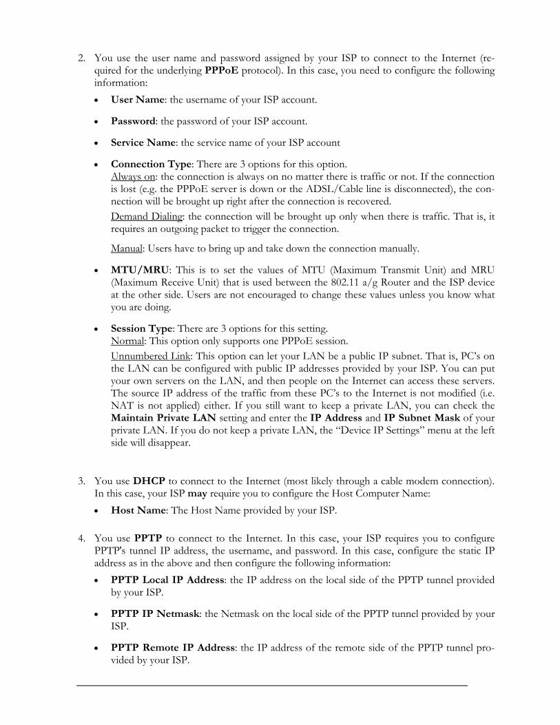
2. You use the user name and password assigned by your ISP to connect to the Internet (re-quired for the underlying PPPoE protocol). In this case, you need to configure the following information: • User Name: the username of your ISP account.
• Password: the password of your ISP account.
• Service Name: the service name of your ISP account
• Connection Type: There are 3 options for this option. Always on: the connection is always on no matter there is traffic or not. If the connection is lost (e.g. the PPPoE server is down or the ADSL/Cable line is disconnected), the con-nection will be brought up right after the connection is recovered. Demand Dialing: the connection will be brought up only when there is traffic. That is, it requires an outgoing packet to trigger the connection.
Manual: Users have to bring up and take down the connection manually.
• MTU/MRU: This is to set the values of MTU (Maximum Transmit Unit) and MRU (Maximum Receive Unit) that is used between the 802.11 a/g Router and the ISP device at the other side. Users are not encouraged to change these values unless you know what you are doing.
• Session Type: There are 3 options for this setting. Normal: This option only supports one PPPoE session. Unnumbered Link: This option can let your LAN be a public IP subnet. That is, PC’s on the LAN can be configured with public IP addresses provided by your ISP. You can put your own servers on the LAN, and then people on the Internet can access these servers. The source IP address of the traffic from these PC’s to the Internet is not modified (i.e. NAT is not applied) either. If you still want to keep a private LAN, you can check the Maintain Private LAN setting and enter the IP Address and IP Subnet Mask of your private LAN. If you do not keep a private LAN, the “Device IP Settings” menu at the left side will disappear.
3. You use DHCP to connect to the Internet (most likely through a cable modem connection). In this case, your ISP may require you to configure the Host Computer Name: • Host Name: The Host Name provided by your ISP.
4. You use PPTP to connect to the Internet. In this case, your ISP requires you to configure PPTP's tunnel IP address, the username, and password. In this case, configure the static IP address as in the above and then configure the following information: • PPTP Local IP Address: the IP address on the local side of the PPTP tunnel provided
by your ISP.
• PPTP IP Netmask: the Netmask on the local side of the PPTP tunnel provided by your ISP.
• PPTP Remote IP Address: the IP address of the remote side of the PPTP tunnel pro-vided by your ISP.
AirLive WLA-5000AP WISP+Client Router Mode 16

• User Name: the username of your ISP account.
• Password: the password of your ISP account.
• Idle time: The Idle Timeout is the number of seconds of "inactivity" before the PPTP connection is taken down. Its value should be between 0 to 60 minutes, with 5 (minutes) being the default value, and 0 meaning the connection will never time out.
5. Cloned MAC Address: Some ISPs expect a PC to be connected to their service, and use the MAC address of this PC’s LAN card for identification purposes. By checking the following “Cloned MAC address” square check box, your WLA-5000AP allows a MAC address to be configured and “cloned” in the router to simulate a PC.
If the device is a PC based on WIN 95/98/Me, you can run winipcfg to find out the MAC Address of its LAN card. If the device is a PC based on WIN 2000/NT/XP, you need to run "ipconfig/all" to find out the MAC address of its LAN card.
17

AirLive WLA-5000AP WISP+Client Router Mode 18
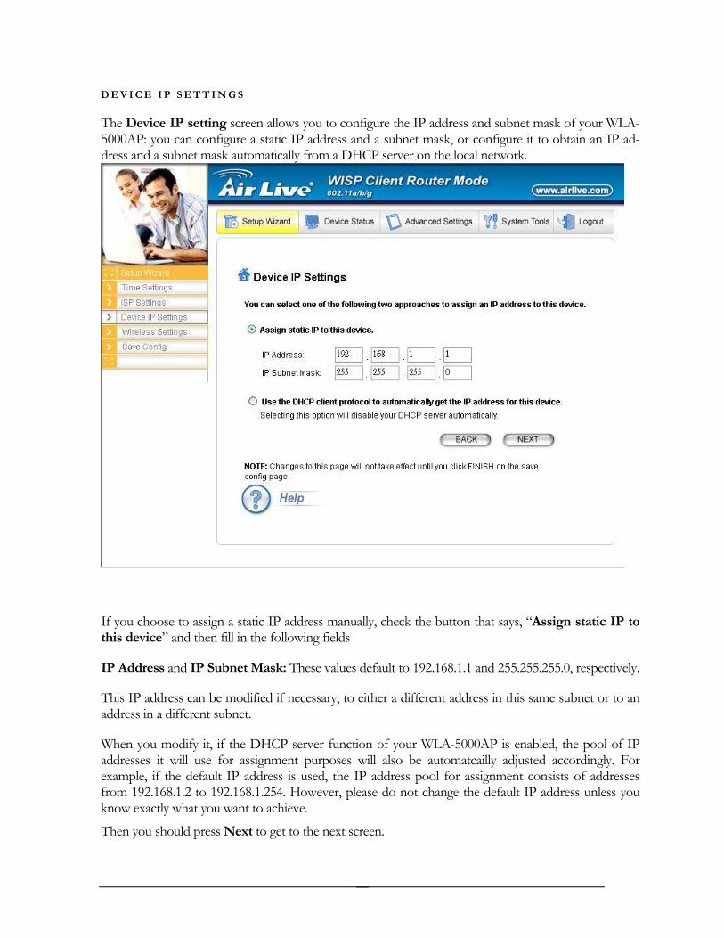
D E V I C E I P S E T T I N G S
The Device IP setting screen allows you to configure the IP address and subnet mask of your WLA-5000AP: you can configure a static IP address and a subnet mask, or configure it to obtain an IP ad-dress and a subnet mask automatically from a DHCP server on the local network.
If you choose to assign a static IP address manually, check the button that says, “Assign static IP to this device” and then fill in the following fields
IP Address and IP Subnet Mask: These values default to 192.168.1.1 and 255.255.255.0, respectively.
This IP address can be modified if necessary, to either a different address in this same subnet or to an address in a different subnet.
When you modify it, if the DHCP server function of your WLA-5000AP is enabled, the pool of IP addresses it will use for assignment purposes will also be automatcailly adjusted accordingly. For example, if the default IP address is used, the IP address pool for assignment consists of addresses from 192.168.1.2 to 192.168.1.254. However, please do not change the default IP address unless you know exactly what you want to achieve.
Then you should press Next to get to the next screen.
19

If you choose to use an external DHCP Server to automatically assign an IP address to your WLA-5000AP check the button that says, “Use the DHCP protocol to automatically get the IP address for this device”, and then press Next to the next screen.
When an IP address is dynamically assigned to the router, its value can change depending on the IP ad-dress assignment policy used by the DHCP server in the network. Since you need to use an IP address to control and manage your WLA-5000AP, without the knowledge of its IP address, in order to access it, you will need to use UPnP (Universal Plug and Play) or other management tools that do not depend on a fixed IP address.
It is strongly recommended that you select the manual static IP address.
C O N F I G U R E Y O U R W I R E L E S S L A N C O N N E C T I O N
In the following configuration screen, you can configure wireless related parameters of your WLA-5000AP:
Network Name (SSID): The SSID is the network name used to identify a wireless network. The SSID must be the same for all devices in the wireless network. Several Routers on a network can have the same SSID. The SSID can be up to 32 characters long. This SSID is used for both radios (i.e. 802.11a and 802.11 b/g).
Disable SSID Broadcasting: An access point periodically broadcasts its SSID, along with other in-formation, which allows client stations to learn its existence while searching for Routers in the wireless network. Select Disable if you do not want the device to broadcast the SSID.
Regulatory Domain: This place shows the regulatory domain where the device is running. This field cannot be changed by regulation.
WLAN standard for Radio 1/2: Here you can set the configuration for each radio.
Mode: For the radio 1, you can select it to run the 802.11a protocol. For the radio 2, you can select it to run the 802.11g only protocol or the 802.11b/g (mix mode)
– allowing both 802.11b and 802.11g to co-exist.
Channel: Select the channel from the available list to match your network settings. All devices in the wireless network must use the same channel and share the total bandwidth available.
Note: The available channels are different from country to country and for different WLAN mode.
Security Policy: You can select different security policy to provide association authentication and/or data encryption.
AirLive WLA-5000AP WISP+Client Router Mode 20

WEP
You can use WEP encryption to protect your data when you are transmitting data in the wireless net-work. There are 3 types of keys: 64 (WEP64), 128 (WEP128), and 152 (WEP152) bits. You can con-figure up to 4 keys using either ASCII or Hexadecimal format.
Key Settings: For WEP64 and WEP128, you can enter a “Passphrase” (a key of up to 32 alphanu-merical characters), choose 64-bit, and press the Generate button to generate four WEP64 keys in the entries below, or choose 128-bit, and press the Generate button to generate one WEP128 key in the first entry.
Alternatively, and for WEP152, you can manually configure each of them.
When you manually configure a key, the length for a WEP64 key must be equal to 5, for a WEP128 key it must be equal to 13, and for a WEP152 key it must be equal to 16. Once you enable the WEP function, please make sure that exactly the same WEP key is configured in both the Wireless Router and client stations.
You can define a key using ASCII or hex characters. A WEP128 ASCII key looks like "An ASCII key!" (13 characters), while a WEP64 hex key looks like "44-12-24-A8-B2" (5 bytes) and “11-22-33-44-55-66-77-88-99-00-A3-BB-2C” as WEP128 hex key. Each set of hexadecimal numbers should be sepa-rated by “-“(dash).
Key Index: You have to specify which of the four keys will be active.
Please note that some Wireless Client Cards allow hexadecimal characters only.
21

WPA-PSK
Wi-Fi Protected Access (WPA) with Pre-Shared Key (PSK) provides better security than WEP keys. It does not require a RADIUS server in order to provide association authentication, but you do have to enter a shared key for the authentication purpose. The encryption key is generated automatically and dynamically.
WPA2-PSK
WPA2 is an improvement on the WPA-PSK standard, and is simply using a shared password for ac-cess to the network..
AirLive WLA-5000AP WISP+Client Router Mode 22
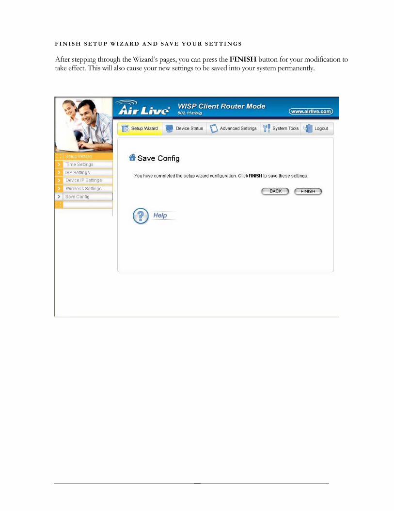
F I N I S H S E T U P W I Z A R D A N D S A V E Y O U R S E T T I N G S
After stepping through the Wizard’s pages, you can press the FINISH button for your modification to take effect. This will also cause your new settings to be saved into your system permanently.
23

Alternatively, you can also click the “BACK” button to go back to previous configuration screens for more changes.
Note: If you change the router’s IP address to a different IP network address space, as soon as you click on FINISH you will no longer be able to communicate with your WLA-5000AP You need to change your IP address and then re-boot your computer in order to resume the communication.
AirLive WLA-5000AP WISP+Client Router Mode 24
Chapter
4 Advanced Settings
This section contains advanced setting procedures for the WLA-5000AP. It describes modifications that normally you may not need for basic system operation. One exception is changing your password: it is highly recommended that you change the default factory setting as soon as you start to use your WLA-5000AP
25

Password Settings
Your WLA-5000AP comes with a default factory password of “airlive”. After you start using the AP, you should change the default password.
To change the password, press the Password Settings button to enter the Password Settings screen, enter the current password followed by the new password twice. The entered characters will appear as asterisks.
If you forgot the password, the only way to recover it is to return the device to its default state as shipped from the factory. To restore the password to the default password, please refer to the section, "What if I forgot the Password?" in the user manual.
26
System Management
Clicking the System Management button allows system related parameters to be configured for the WLA-5000AP.
Remote Management: The remote management feature allows you to manage your WLA-5000AP remotely through the use of an HTTP browser.
The system allows you to (1) allow remote management from all WAN IP addresses, to (2) allow remote management from up to two WAN IP addresses, or to (3) disallow remote manage-ment from any WAN IP addresses.
System Administration: The router allows you to designate special port numbers other than the stan-dard 80 for http for remote management. It also allows you to specify the duration of idle time (inac-tivity) before a web browser session times out. The default time-out value is 10 minutes.
UPnP: The router's Universal Plug and Play (UPnP) feature allows a Windows XP/ME PC to dis-cover the router and automatically show an icon in the task bar on the screen. You can double-click the icon to access the router directly (without having to specify its IP address).
Disable Ping: "Ping" is a utility for testing the connectivity. Response to a ping can be disabled, such as when you do not want the router to be accessed (e.g., attacked) from the Internet.
Syslog: Syslog is an IETF (Internet Engineering Task Force - the Internet standards body)-conformant standard for logging system events (RFC-3164). When the WLA-5000AP encounters an error or warning condition (e.g., a log-in attempt with an invalid password), it will create a log in the system log table. To be able to remotely view such system log events, you need to check the Enable Syslog box, configure the IP address of a PC where a Syslog daemon is running in the background. When doing so, the WLA-5000AP will send logged events over the network to the PC for future view-ing.
Syslog server IP address: The IP address of the PC where the Syslog daemon is running.
27

AirLive WLA-5000AP WISP+Client Router Mode 28

SNMP Settings
This screen allows you to configure SNMP parameters including the system name, the location and contact information. Additionally, you can configure the WLA-5000AP to send SNMP Traps to re-mote SNMP management stations. Traps are unsolicited alert messages that WLA-5000AP sends to remote management stations.
System Name: A name that you assign to your WLA-5000AP. It is an alphanumeric string of up to 30 characters.
System Location: Description of where your WLA-5000AP is physically located. It is an alphanu-meric string of up to 60 characters.
System Contact: Contact information for the system administrator responsible for managing your WLA-5000AP. It is an alphanumeric string of up to 60 characters.
Community String For Read: If you intend the router to be managed from a remote SNMP man-agement station, you need to configure a read-only “community string” for read-only operation. The community string is an alphanumeric string of up to 15 characters.
29
Community String For Write: For read-write operation, you need to configure a write “community string”.
A trap manager is a remote SNMP management station where special SNMP trap messages are gener-ated (by the router) and sent to in the network.
You can define trap managers in the system.
You can add a trap manager by entering a name, an IP address, followed by pressing the ADD but-ton.
You can delete a trap manager by selecting the corresponding entry and press the DELETE SE-LECTED button.
You enable a trap manager by checking the Enable box in the corresponding entry or disable the trap manager by un-checking the Enable box.
AirLive WLA-5000AP WISP+Client Router Mode 30

DHCP Server Settings
The DHCP server option allows the WLA-5000AP to assign IP addresses to DHCP client devices on your wired or wireless LAN to obtain IP addresses automatically.
If you want the Router to act as a DHCP server and assign private IP addresses to requesting DHCP clients on the LAN, you need to check the Enable DHCP Server box.
31

You can select one of the following two ways to assign IP addresses:
Assigns IP addresses to wired or wireless clients from the following range:
When IP addresses are assigned to a requesting DHCP client, after the “lease time”, the cli-ent is expected to renew the lease. Its default value is 10080 minutes.
The from and to range of IP addresses to be assigned to requesting DHCP clients can be configured manually, with the default being 2 to 254.
After you enter the information, you should press APPLY.
Assigns the following IP address to the client with the following MAC address:
You can also specify the IP address to be assigned to a device with a pre-configured MAC ad-dress.
You can add such a mapping by entering a MAC address, and the IP address to be assigned, fol-lowed by pressing the ADD button. Up to 20 mappings can be added.
You can delete a mapping by selecting the corresponding entry and press the DELETE SE-LECTED button.
DHCP Table: Press this button will cause the screen to jump to DHCP client table page.
AirLive WLA-5000AP WISP+Client Router Mode 32
Multiple DMZ
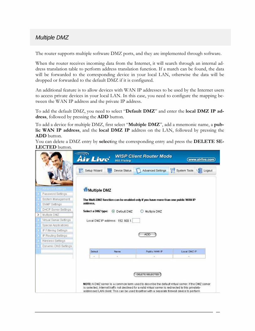
The router supports multiple software DMZ ports, and they are implemented through software.
When the router receives incoming data from the Internet, it will search through an internal ad-dress translation table to perform address translation function. If a match can be found, the data will be forwarded to the corresponding device in your local LAN, otherwise the data will be dropped or forwarded to the default DMZ if it is configured.
An additional feature is to allow devices with WAN IP addresses to be used by the Internet users to access private devices in your local LAN. In this case, you need to configure the mapping be-tween the WAN IP address and the private IP address.
To add the default DMZ, you need to select “Default DMZ” and enter the local DMZ IP ad-dress, followed by pressing the ADD button. To add a device for multiple DMZ, first select “Multiple DMZ”, add a mnemonic name, a pub-lic WAN IP address, and the local DMZ IP address on the LAN, followed by pressing the ADD button. You can delete a DMZ entry by selecting the corresponding entry and press the DELETE SE-LECTED button.
33
Virtual Server Settings
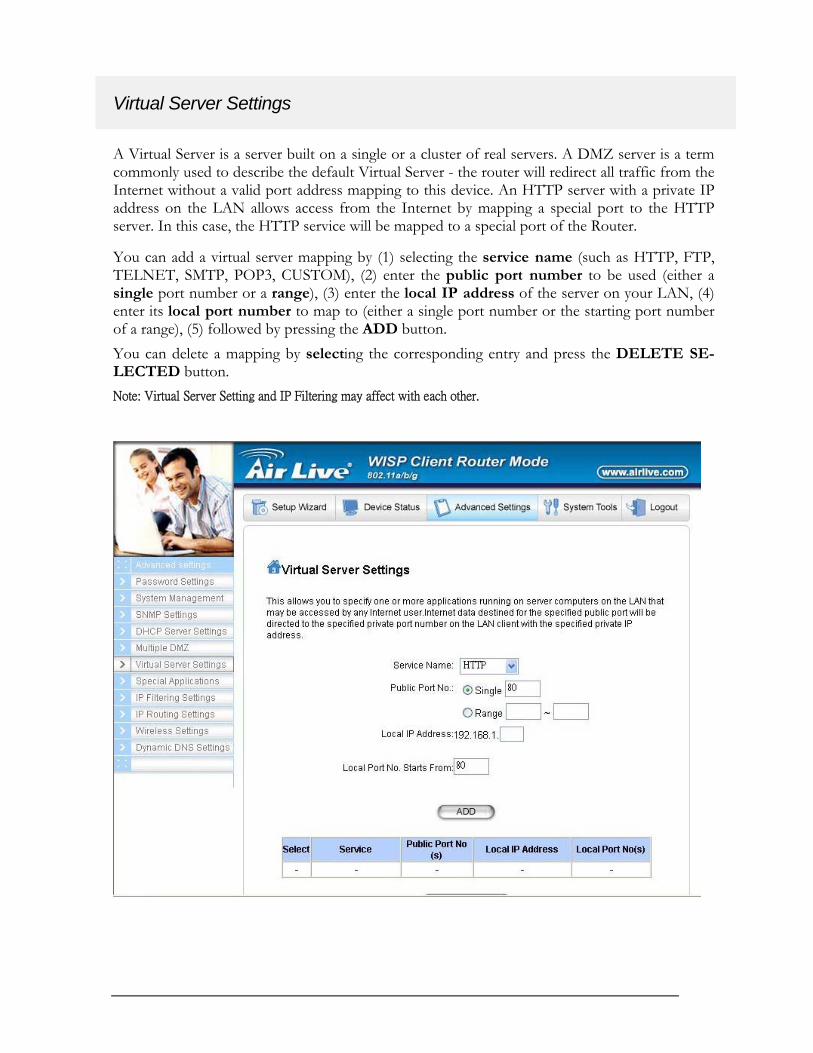
A Virtual Server is a server built on a single or a cluster of real servers. A DMZ server is a term commonly used to describe the default Virtual Server - the router will redirect all traffic from the Internet without a valid port address mapping to this device. An HTTP server with a private IP address on the LAN allows access from the Internet by mapping a special port to the HTTP server. In this case, the HTTP service will be mapped to a special port of the Router.
You can add a virtual server mapping by (1) selecting the service name (such as HTTP, FTP, TELNET, SMTP, POP3, CUSTOM), (2) enter the public port number to be used (either a single port number or a range), (3) enter the local IP address of the server on your LAN, (4) enter its local port number to map to (either a single port number or the starting port number of a range), (5) followed by pressing the ADD button. You can delete a mapping by selecting the corresponding entry and press the DELETE SE-LECTED button. Note: Virtual Server Setting and IP Filtering may affect with each other.
AirLive WLA-5000AP WISP+Client Router Mode 34

Special Applications
Special applications such as some Internet games are getting to be increasingly popular. These applications usually work in the following manner:
A client can start an Internet game by first registering with a game server on the Internet. Other clients can, using the corresponding protocol, join the game by checking with the server and de-ciding if to join the game. A client can "leave" the game at any time.
If the initiating client is behind your router, you need to add the application by performing the following configuration:
Select an application: Select an application that you want to add to the supported list. You should choose "Other" if your application is not explicitly shown in the list.
Name: You can provide a mnemonic name.
Trigger Port: You need to specify, based on instructions provided by your application’s user manual, the (UDP/TCP) port number in the router that the initiating client uses to start an Internet game.
Trigger Type: Select UDP, TCP, or both for the trigger port.
Opened ports: You need to specify the port numbers in the router that joining clients can use to communicate with the initiating client, again based on instructions provided by your application user manual.
Public Type: Select UDP, TCP, or both for the Opened ports.
After you finish the above, you press the ADD button to add an entry to the table.
You can delete an entry by selecting the corresponding entry and press the DELETE SE-LECTED button.
35

IP Filtering Settings
Three mutually exclusive rules can be defined to forward/filter IP packets based on their IP ad-dress and/or port numbers.
Disable IP filtering: If this is selected, the IP filtering feature is disabled. No IP filtering will be performed.
GRANT IP access: When this is elected, packets received from/transmitted to WAN with specified (source or destination) IP addresses will be allowed/forwarded.
DENY IP access: Packets received from/transmitted to WAN with the specified IP ad-dresses will be denied/filtered.
Once a choice is made, the choice applies to all filtering rules.
To define/add an IP filtering rule, enter the following information
• Name: The name of the filter
• IP Protocol: TCP or UDP
AirLive WLA-5000AP WISP+Client Router Mode 36

• Apply to: You need to select whether the filtering rule should apply to packets outbound for the Internet or inbound from the Internet.
• Source IP address: you can select Any, Single IP, or a Network (of source IP ad-dresses).
• Source Port: you can select Any, Single, or a Range of port numbers.
• Destination IP address: Any, Single IP, or a Network (of destination IP addresses).
• Destination Port: you can select Any, Single, or a Range of port numbers. After you finish the above, you press the ADD button to add the entry to the table. There are up to 32 IP filtering rules could be configured.
You can delete an entry by selecting the corresponding entry and press the DELETE SE-LECTED button.
Please Note that IP filtering is a sophisticated feature that can severely impact your Router op-eration. Please be sure that you fully understand it before you use this feature. If you make any mistakes, it can produce dramatic and potentially undesirable results.
37

IP Routing Settings
Dynamic Routing: enable gateway to exchange the routing table dynamically through LAN port. Currently you can choose to use RIPv1 or RIPv2 with Send enabled (active mode) or disabled (passive mode).
Static Routing: If you have routers on your LAN or WAN, you can configure static routes on the a/g Router to route network traffic to a specific, predefined destination. The WLA-5000AP routes packets based only on the packet's destination not on the source of a packet.
Static Routes are configured when network traffic is directed to a specific destination on the network whether it is the LAN or WAN. For instance, you can configure the WLA-5000AP to route traffic des-tined to a particular network to a specific router on the LAN or WAN using the following steps:
1. Enter the IP address of the destination network in the Destination Network field.
2. Enter the subnet in the Subnet Mask field.
3. Enter the IP address of the specific router in the Gateway IP Address field.
4. Select LAN or WAN, where is the specific router is, from the Interface menu.
6. Click Add.
IP Routing Table: The Routing Table shows a list of destinations that the IP software maintains on each host and router. The destination network IP address, subnet mask, gateway address, and the cor-responding interface are displayed.
Note: The WLA-5000AP can support up to 128 static route entries.
AirLive WLA-5000AP WISP+Client Router Mode 38

Wireless Settings
You can use this screen to configure various parameters of your WLA-5000AP.
Beacon Interval: The WLA-5000AP broadcasts beacon frames regularly to announce its existence. The beacon Interval specifies how often beacon frames are transmitted - in time unit of milliseconds. Its default value is 100; a valid value should be between 20 and 1000.
RTS Threshold: RTS/CTS frames are used to gain control of the medium for transmission. Any uni-cast (data or control) frames larger than the specified RTS threshold must be transmitted following the RTS/CTS handshake exchange mechanism. The RTS threshold should have a value between 0 and 2347 bytes, with a default value of 2347. A value of zero activates the RTS/CTS handshake before every transmission. It is recommended that this value does not deviate from the default too much.
Fragmentation: When the size of a unicast frame exceeds the fragmentation threshold, the frame will be fragmented before transmission. The threshold should have a value of 256-2346 bytes, with a de-fault value of 2346. If you experience a high packet error rate, you should slightly decrease the Frag-mentation Threshold.
DTIM Interval: The WLA-5000AP buffers packets for stations that operate in the power-saving mode. A Delivery Traffic Indication Message (DTIM) contains information on which power-conserving stations have packets waiting to be received. The DTIM interval specifies how often bea-con frames should contain DTIMs. It should have a value between 1 and 255, with a default value of 3.
39

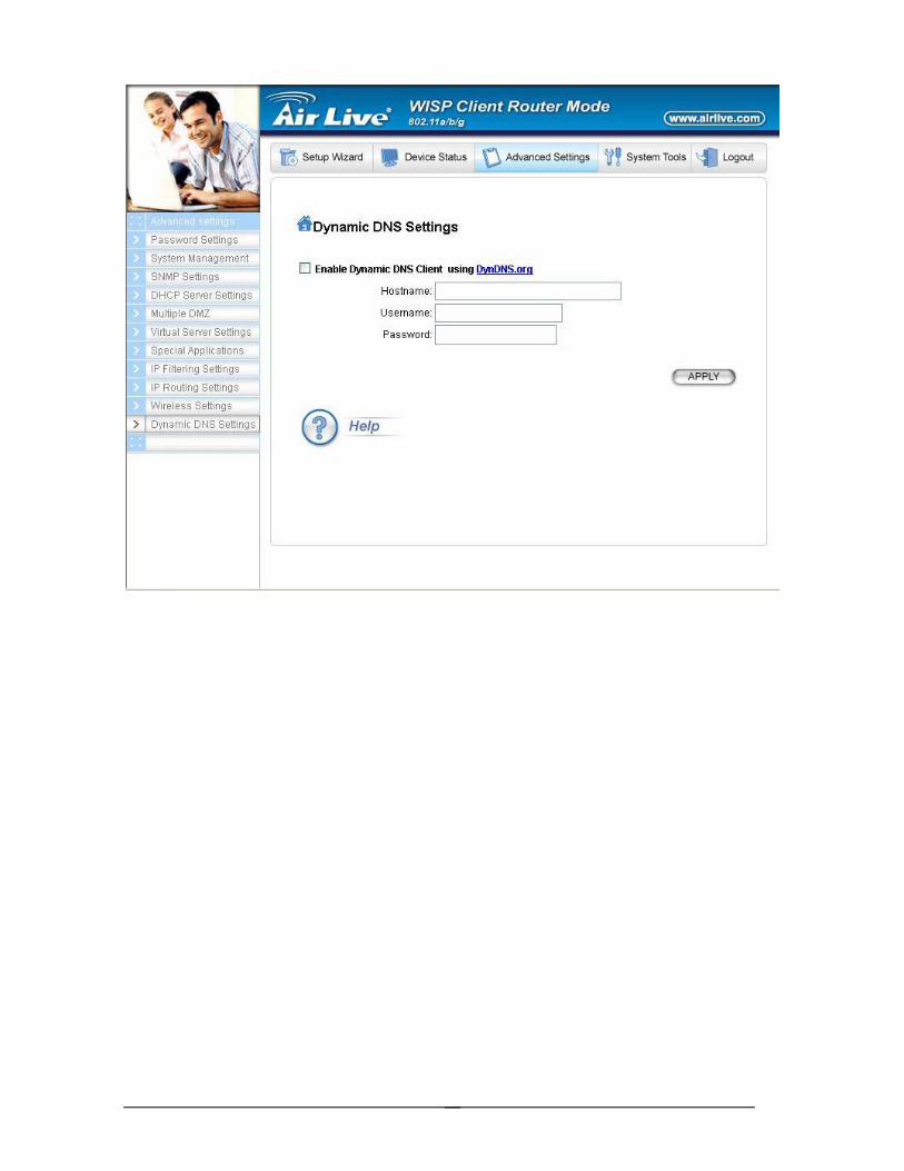
Dynamic DNS Settings
Some people advertise the IP addresses of their routers so that Internet users can access these routers (which is actually to access virtual servers behind these routers) using these IP addresses. However, for those routers that are assigned dynamic IP addresses from the ISP, this approach requires additional work (since the addresses assigned are not always the same).
The WLA-5000AP implements the dynamic DNS feature so that each time it is booted, it will re-register its domain-name-to-IP-address mapping with the dynamic DNS server you use (cur-rently only DynDNS.org is supported), the service provider that provides domain name to IP address mapping. This is so that you can advertise your router by providing your domain name, while Internet users can access the router using the domain name, not the router’s IP address.
To activate this feature, you need to check the “Enable Dynamic DNS Client using DynDNS.org” box first, and then configure the following parameters:
Hostname: the hostname (domain name) registered with DynDNS.org by you.
Username: the username required to log in to the domain name server maintained by DynDNS.org.
Password: the password required to log in to the domain name server maintained by DynDNS.org.
AirLive WLA-5000AP WISP+Client Router Mode 40
41

M
T
anaging your WLA-5000AP
his Chapter covers other management aspects of your WLA-5000AP:
How to view the device status
Chapter
5 How to view the system log
How to upgrade your WLA-5000AP firmware
How to save or restore configuration changes
How to reboot your WLA-5000AP
What if you forgot the password
How to View the device Status
You can monitor the system status and get general device information from the Device Information screen:
AirLive WLA-5000AP WISP+Client Router Mode 42

How to View the System Log
The WLA-5000AP maintains a system log that you can use to track events that have occurred in the system. Such event messages can sometimes be helpful in determining the cause of a problem that you may have encountered.
You can select System Log on the left to view log events recorded in the system. The System Log en-tries are shown in the main screen along with the log level, the severity level of messages that are being displayed (a low number such as 2 means critical), and the uptime, the amount of time since the WLA-5000AP was last reset. The maximum number of entries is 128. If there are more than 128 entries, older entries will be deleted.
43

DHCP Client Table
The DHCP client table lists current DHCP clients connected with its host name, IP address, MAC address, expiration time, and entry type.
Bridge Table
The bridge table shows all MAC entries learned from the wired LAN interface, wireless clients, and WDS peers.
AirLive WLA-5000AP WISP+Client Router Mode 44

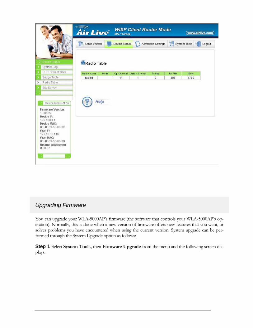
Radio Table
The radio table shows the information of each radio, including the current mode, channel, number of clients associated, number of packets transmitted and received, and number of errors happened.
45
Upgrading Firmware
You can upgrade your WLA-5000AP’s firmware (the software that controls your WLA-5000AP’s op-eration). Normally, this is done when a new version of firmware offers new features that you want, or solves problems you have encountered when using the current version. System upgrade can be per-formed through the System Upgrade option as follows:
Step 1 Select System Tools, then Firmware Upgrade from the menu and the following screen dis-plays:
AirLive WLA-5000AP WISP+Client Router Mode 46

Step 2: To update the WLA-5000AP firmware, first download the firmware from the distributor’s web site to your local disk. Then from the above screen enter the path and filename of the firmware (or click Browse to select the path and filename of the firmware). Next, Click the Upgrade button.
The new firmware will begin loading to your WLA-5000AP. After a message appears telling you that the operation is complete, you need to reset the system to have the new firmware take effect.
Note: It is recommended that you do not upgrade your WLA-5000AP if you are happy with its operation.
47

How to Save or Restore Configuration Changes
You can save system configuration settings to a file, and later download it back to the WLA-5000AP system by following the steps below.
Step 1 Select Configuration Save and Restore from the System Tools menu and the following screen displays:
Step 2 Click SAVE TO FILE and then select a local file to save to, or click RESTORE FROM FILE and then select a local file to upload.
48

How to Restore the System Settings to the Factory Defaults
You can restore the system settings to the factory defaults.
Step 1 Select Factory Default from the System Tools menu and the following screen displays:
Step 2 Click YES to restore the system configurations to the factory defaults, and the system will re-boot automatically.
49

How to Reboot your WLA-5000AP
You can reset your WLA-5000AP from the Brower. To reset it:
Step 1 Select Reboot System from the System Tools menu, the following screen shows:
Step 2 Click YES to reset the WLA-5000AP.
Note: Resetting the WLA-5000AP disconnects any active clients, and therefore will disrupt any current data traffic.
AirLive WLA-5000AP WISP+Client Router Mode 50

What if you Forgot the Password?
If you forgot the password, the only way to recover is to clear the device configuration and return the unit to its original state as shipped from the factory. You can do this by pressing the hardware “re-store” button on the device for “2 seconds”. Please note that this will require you to re-enter all of your configuration data.
51

Specification Product Name IEEE 802.11a/g Wireless LAN AP (WISP Client Router mode) OS Linux® 2.4.18 kernel
Standard
• IEEE 802.11a • IEEE 802.11b • IEEE 802.11g • IEEE 802.1x • IEEE 802.3u
WLAN Network Architecture Type • Infrastructure • Bridge Mode (WDS)
Wireless Transfer Data Rate for IEEE 802.11a Draft Standard
IEEE 802.11a Standard: 54, 48, 36, 24, 18, 12, 9 & 6 Mbps with auto fallback
Wireless Transfer Data Rate for IEEE 802.11g Draft Standard
IEEE 802.11g Standard: 54, 48, 36, 24, 18, 12, 9 & 6 Mbps with auto fallback
Wireless Transfer Data Rate for IEEE 802.11b
11, 5.5, 2 & 1 Mbps with auto fallback
Physical Specification
• External Power Adapter with DC5v/2A Input • Dimension: 164.3(L) x 170(W) x 36.5(H) mm • Desktop Installation • Wall/Ceiling Mountable
Hardware & Antenna
• 3 x RJ45 (4x 10/100 Mbps Ethernet Switch Auto MDI/MDI-X) for LAN ports
• 1 x RJ45 for WAN • 1 x RJ45 for DMZ • 1 x Reset Button • 2x External Antenna • 9 x LED: 1 x Power; 1 x Diag; 1 x WLAN; 1 x WAN
(LINK/ACT); 4 x LAN (LINK/ACT); 1 x DMZ (LINK/ACT)
DHCP Server • Build-in DHCP server • Support static DHCP assignment
Security, VPN Support • IP Sec, L2TP, PPTP pass through
NAT & Firewall
• Support special applications including H323, NetMeeting, internet gaming
• Default private receiver (Software DMZ) • Virtual server • IP Filtering
IP Routing • Rip v1 & v2 • Static and default route
Management
• Web-Based Management Tool • UPnP • SNMP V1 & V2 • MIB: Ethernet, MIB II, 802.11 • Command line interface with Telenet • Upload & download test-based configuration file vis HTTP
browser • Firmware upgrade via HTTP browser • SysLog
DNS • DNS relay & Dynamic DNS
WAN Encapsulation • Static IP • DHCP client; PPPoE client • PPTP client
IP Address Assignment • DHCP Client • Static IP Address
Environmental Specification • Operation Temperature: 00 ~400 C. • Storage Temperature: -200 ~ 650 C • Operating Humidity: 10% ~90% (without Condensation)
EMC Certification • CE
Certificate • Wi-Fi Class 5 GHz 802.11a, Wi-Fi Class 2.4 GHz 802.11g (Planning)
AirLive WLA-5000AP WISP+Client Router Mode 52


![How–To setup Wi-Fi Client Router Mode as [CPE] connect to [WISP AP] & Using Existing Broadband Router to Create New Sub-Network](https://static.fdocuments.in/doc/165x107/55654719d8b42ad7648b51b7/howto-setup-wi-fi-client-router-mode-as-cpe-connect-to-wisp-ap-using-existing-broadband-router-to-create-new-sub-network.jpg)