Willy Sudiarto Raharjo Aditya Wikan Mahastama · Memanfaatkan banyak teori graf ... Kesamaan...
34
PEMODELAN SISTEM PERANGKAT LUNAK Willy Sudiarto Raharjo Aditya Wikan Mahastama UNIV KRISTEN DUTA WACANA / TI – GENAP 0910 5 Data Flow Diagram
Transcript of Willy Sudiarto Raharjo Aditya Wikan Mahastama · Memanfaatkan banyak teori graf ... Kesamaan...

PEMODELAN SISTEM PERANGKAT LUNAK
Willy Sudiarto RaharjoAditya Wikan Mahastama
UNIV KRISTEN DUTA WACANA / TI – GENAP 0910
5
Data Flow Diagram

Systems AnalysisFocus is the logical view of the system, not the
physical“What” the system is to accomplish, not how
Tools:data flow diagramsdata dictionaryprocess specificationentity-relationship diagrams

Data Flow Diagram: "a network representation of a system. The system
may be automated, manual, or mixed. The DFD portrays the system in terms of its component pieces, with all interfaces among the components indicated."
- Tom DeMarcohence DFDs:
focus on the movement of data between external entities and processes, and between processes and data stores

Data Flow DiagramDiagram yang menggambarkan aliran data pada sebuah sistem softwareDiciptakan pada tahun 1970anMemanfaatkan banyak teori grafTidak menjelaskan urutan sebuah proses Tidak menjelaskan algoritmaFokus pada aliran data
Input/Output dari dan ke sistemData dari dan atau ke proses atau sumber data

Contoh Data Flow Diagram
data store
process
external entity
data flow

Data Flow Diagrams are:
Used to perform structured analysis to determine logical requirements
A graphical tool, useful for communicating with users, managers, and other IS personnel
Useful for analyzing existing as well as proposed systems
A relatively simple technique to learn and use

Mengapa Perlu Process Modeling dengan DFD?
Understand components of current logical or physical system for purpose of rebuilding in a different physical form/technology, possibly with some changed functionality
Find inefficiencies in current systemRe-engineer current systemPada sistem kompleks, data yang mengalir sangat
banyak dan bisa membingungkanKesamaan persepsi tentang sistem secara
keseluruhan

Sources/Sinks(external entities)
• Any class of people, an organization, or another system which exists outside the system you are studying.
• Sistem dan entitas eksternal bertukar data dalam bentuk data flows.
• Harus diberi nama - biasanya kata benda yang menunjukkan sebuah individu entitas
source/
sink
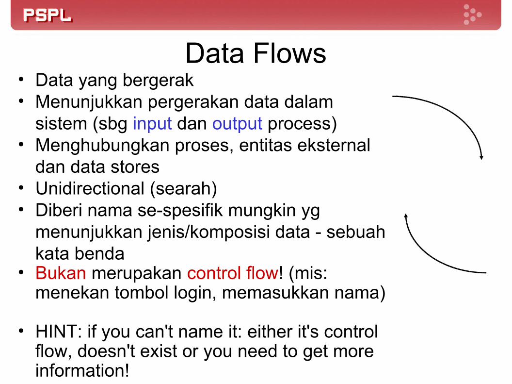
Data Flows• Data yang bergerak• Menunjukkan pergerakan data dalam
sistem (sbg input dan output process)• Menghubungkan proses, entitas eksternal
dan data stores• Unidirectional (searah)• Diberi nama se-spesifik mungkin yg
menunjukkan jenis/komposisi data - sebuah kata benda
• Bukan merupakan control flow! (mis: menekan tombol login, memasukkan nama)
• HINT: if you can't name it: either it's control flow, doesn't exist or you need to get more information!

Processes• Mentransformasikan data
flow yang masuk menjadi data flow yang keluar
• Diberi nama berupa kombinasi KATA KERJA dasar dan OBYEK examples:create_exception_report validate_input_characters calculate_discountHitung Gaji Bersih
process
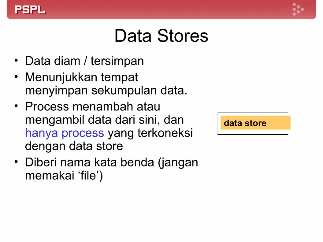
Data Stores• Data diam / tersimpan• Menunjukkan tempat
menyimpan sekumpulan data.• Process menambah atau
mengambil data dari sini, dan hanya process yang terkoneksi dengan data store
• Diberi nama kata benda (jangan memakai ‘file’)
data store
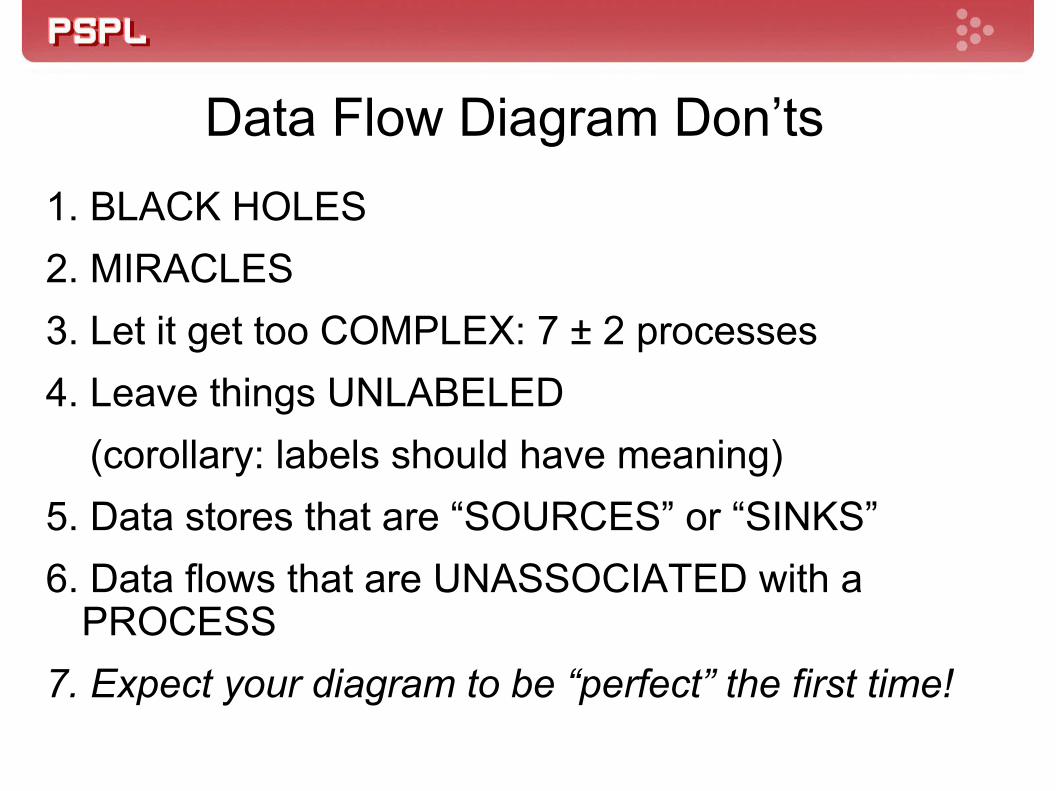
Data Flow Diagram Don’ts1. BLACK HOLES2. MIRACLES3. Let it get too COMPLEX: 7 ± 2 processes4. Leave things UNLABELED (corollary: labels should have meaning)5. Data stores that are “SOURCES” or “SINKS”6. Data flows that are UNASSOCIATED with a
PROCESS7. Expect your diagram to be “perfect” the first time!

Data Flow Diagram Don’ts
process1. ‘Black Hole’
process 2. ‘It’s a Miracle’

Data Flow Diagram Don’ts
A.2
A.1
ds-1
data
4. Leave Things Unlabeled
Labels Should Have Meaning!!
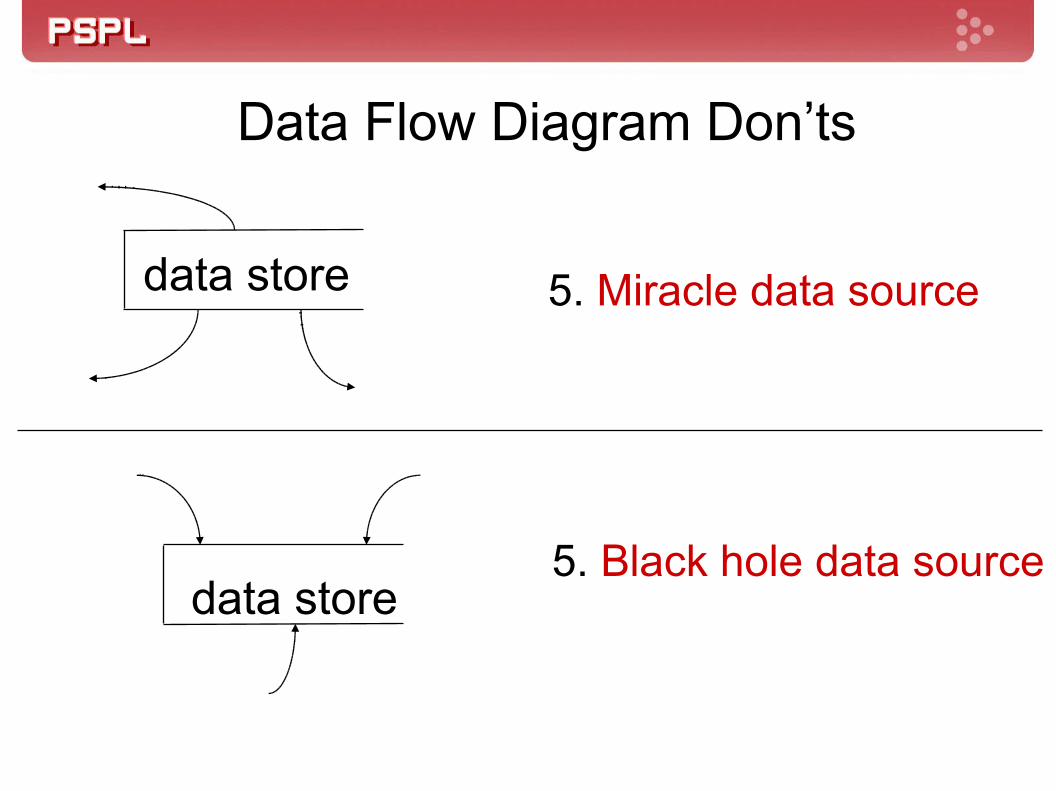
Data Flow Diagram Don’ts
data store 5. Miracle data source
data store5. Black hole data source

Data Flow Diagram Don’ts6. Data Flows Unassociated With a Process
entity to entitydata store to entity - or reverse
data store to data store

Diagramming A System
Beberapa DFD dibutuhkan untuk merepresentasikan sebuah sistem
DFD dibuat dalam tingkatan-tingkatan detail (level), semakin tinggi semakin detail

Different Types of DFDs
Context diagramLevel-0 diagram (System diagram /
Overview diagram)
Level-n diagram (Primitive diagram)

Context Diagram
Mendefinisikan ruang lingkup (scope) sistem dengan mendefinisikan batasan sistem (system boundary)
berisi: satu process (yang merepresentasikan seluruh
sistem)semua sources/sinks (external entities)data flows yang menghubungkan process dengan
external entities

Contoh Context Diagram
RegistrationSystem
studentcourse selections
businessoffice
Registration detailsschedule

Constructing a Context Diagram
identify and list sources/sinks (external entities)identify and list inputs to and outputs from
sources/sinks (external entities)create context diagram
Level-0 Diagram
Menggambarkan seluruh proses-proses yang terjadi dalam sistem
Memiliki satu process untuk setiap langkah proses utama
Data flows dari context diagram juga muncul di sini (level balancing)
Dapat hanya memiliki satu data store saja untuk merepresentasikan semua data di level ini secara agregat
Dapat memiliki banyak duplikasi entitas eksternal dan data stores to increase legibility

Drawing a Level-0 Diagram
list the major data storeslist major business stepsdraw a segment for each business stepassemble into single DFDre-organize until satisfiednumber processes

Functional DecompositionMirip dengan serangkaian pemetaan yang lebih detailiterative process of breaking the description of a
system into finer and finer detail to create a set of charts in which one process on a given chart is explained in greater detail on another chart
Disebut juga sebagai exploding, partitioning, atau leveling
Memerlukan pertimbangan (judgment) anda sendiri untuk menentukan apa yang akan digambarkan pada setiap level

Lower Level Diagrams
Melakukan leveling terhadap processes yang ada di level-0 diagram
Setiap process direpresentasikan oleh DFD-nya sendiri
Lakukan balancing datadata flows on upper level appear on lower level, ordata flows on upper level are broken into component
pieces with components shown on lower levelSetiap peningkatan lower level menunjukkan detail
yang lebih tinggiGunakan konvensi penomoran yang sudah ada

Balancing DFDs
conserve data from level to level (data flow yang ada di level sebelumnya harus tetap ada, atau dipecah menjadi komponen-komponen yang lebih kecil) jangan memaksakan pemecahan kalau memang tidak perlu dipecah!
inputs and outputs on the higher level must reappears somewhere on the lower level

Advanced Rules
Composite data flow on one level can be split into its component data flows on the next level - but new data cannot be added and all data in the composite must be included in the sub-flows
The inputs to a process must be sufficient to produce the outputs.
May repeat data stores or external entities to avoid crossing lines

Additional Guidelines
the inputs to a process are different from the outputs of that process
objects in a set of DFDs have unique namesdo not change data flow names on lower levels unless
you are decomposing a data flow into component pieces.
never explode a single process into another single process. If you cannot partition the process, then the lower level DFD is not needed.

Other Questions about Lower level diagrams
1. How deep? (how many levels?)if the process has only one input or one output, probably
cannot partition further;can you describe the process in English in about 1/2
page?
2. How broad? (how many processes on a level?)7 ± two is a reasonable heuristicmay temporarily place much of the system on a single
diagram then re-draw into separate levels


DFD HowTo
Buat Context Diagram (DFD Level 0)Interaksi antara sistem dengan entitas eksternal
Perjelas dengan DFD Level 1Dekomposisi sistem menjadi sub proses
Proses kompleks bisa dipecah menjadi Level 2Tidak ada batasan sampai berapa level, akan tetapi biasanya cuma sampai level 2/3

Panduan Pembuatan DFD
Pilih nama yang berarti untuk proses, flow, dan storeBeri nomor pada prosesHindari DFD yang terlalu kompleks
Gunakan sub level untuk menggambarkan proses yang terlalu detail
Pastikan DFD konsisten dengan level diatas/bawahnyaLakukan repetisi sampai DFD jelas dan mudah dipahami

http://yourdon.com/strucanalysis/wiki/index.php?title=Chapter_9http://pcbfaculty.ou.edu/classfiles/MIS%203373/section%20901/Lectures%20for%20Test%201/Lecture%203.ppt


![Aditya Wikan Mahastama - pintarmultimedia.com · APA ITU CITRA DIGITAL? • Citra Digital: sampeldiskretf [x,y] yang merepresentasikancitrakontinuf (x,y) • Setiapelemendarisenaraidua-dimensif](https://static.fdocuments.in/doc/165x107/5cd063e488c993966d8deef9/aditya-wikan-mahastama-apa-itu-citra-digital-citra-digital-sampeldiskretf.jpg)