White paper The future of condenser bushing technology · PDF fileThe future of condenser...
6
Abstract The basic construction of a condenser bushing has remained the same for the last 60 plus years. The only changes have been mostly manufacturing practices and processes. Due to field issues and concerns with safety, security, field mainte- nance, and environmental regulations, our world within the Uni- ted States on condenser bushings is about to change. Within this paper we will briefly address the history of Resin Bonded Porcelain Insulator Bushings, Oil Impregnated Porcelain Insu- lated Bushings, and the future with Resin Impregnated Paper Type Bushings, and Resin Impregnated Synthetic Type Bushings utilizing Silicone Rubber Insulators and Epoxy Type Bushings. Our focus will be on basic design, materials, and the pros and cons of “Dry Type Condenser” Silicone Rubber Insulator Bus- hings. For the discussion of this paper we will only address bushing apparatus being used on power transformers. Introduction The basic construction of condenser bushings 15 kV through 765 kV has not changed in over 60 years with the majority being an oil impregnated condenser body within a porcelain insulator envelope on the upper air end and lower oil end of the bushing. There is a need to be on the same page with regards to design and industry nomenclature. The following definitions will be discussed: The future of condenser bushing technology and materials White paper
Transcript of White paper The future of condenser bushing technology · PDF fileThe future of condenser...

Abstract The basic construction of a condenser bushing has remained the same for the last 60 plus years. The only changes have been mostly manufacturing practices and processes. Due to field issues and concerns with safety, security, field mainte-nance, and environmental regulations, our world within the Uni-ted States on condenser bushings is about to change. Within this paper we will briefly address the history of Resin Bonded Porcelain Insulator Bushings, Oil Impregnated Porcelain Insu-lated Bushings, and the future with Resin Impregnated Paper Type Bushings, and Resin Impregnated Synthetic Type Bushings utilizing Silicone Rubber Insulators and Epoxy Type Bushings. Our focus will be on basic design, materials, and the pros and cons of “Dry Type Condenser” Silicone Rubber Insulator Bus-hings.
For the discussion of this paper we will only address bushing apparatus being used on power transformers.
Introduction The basic construction of condenser bushings 15 kV through 765 kV has not changed in over 60 years with the majority being an oil impregnated condenser body within a porcelain insulator envelope on the upper air end and lower oil end of the bushing.
There is a need to be on the same page with regards to design and industry nomenclature. The following definitions will be discussed:
The future of condenser bushing technology and materialsWhite paper
2 Future of condenser bushings | ABB white paper
Definition of Condenser Bushing: A bushing in which me-tallic or nonmetallic conducting layers are arranged within the insulating material for the purpose of controlling the distribution of the electric field of the bushing, both axially and radially by capacitive grading.
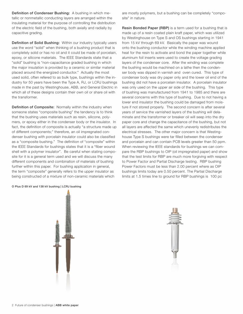
Definition of Solid Bushing: Within our industry typically users use the word “solid” when thinking of a bushing product that is completely solid or has no oil and it could be made of porcelain, epoxy, or silicone materials. The IEEE Standards state that a “solid” bushing is “non-capacitance graded bushing in which the major insulation is provided by a ceramic or similar material placed around the energized conductor.” Actually the most used solid, often refered to as bulk type, bushings within the in-dustry for 50 years have been the Type A, RJ, or LCRJ bushings made in the past by Westinghouse, ABB, and General Electric in which all of these designs contain their own oil or share oil with the transformer.
Definition of Composite: Normally within the industry when someone states “composite bushing” the tendency is to think that the bushing uses materials such as resin, silicone, poly-mers, or epoxy either in the condenser body or the insulator. In fact, the definition of composite is actually “a structure made up of different components;” therefore, an oil impregnated con-denser bushing with porcelain insulator could also be classified as a “composite bushing.” The definition of “composite” within the IEEE Standards for bushings states that it is a “fiber wound shell with a polymer insulator”. Be careful when stating compo-site for it is a general term used and we will discuss the many different components and combination of materials of bushing further within this paper. For bushing application in general, the term “composite” generally refers to the upper insulator as being constructed of a mixture of non-ceramic materials which
are mostly polymers, but a bushing can be completely “compo-site” in nature.
Resin Bonded Paper (RBP) is a term used for a bushing that is made up of a resin coated plain kraft paper, which was utilized by Westinghouse on Type S and OS bushings starting in 1941 from 15 kV through 69 kV. Basically the paper was wound onto the bushing conductor while the winding machine applied heat for the resin to activate and bond the paper together while aluminum foil inserts were used to create the voltage grading layers of the condenser core. After the winding was complete the bushing would be machined on a lathe then the conden-ser body was dipped in varnish and oven cured. This type of condenser body was dry paper only and the lower oil end of the bushing did not have a porcelain insulator. A porcelain insulator was only used on the upper air side of the bushing. This type of bushing was manufactured from 1941 to 1985 and there are several concerns with this type of bushing. Due to not having a lower end insulator the bushing could be damaged from mois-ture if not stored properly. The second concern is after several years of service the varnished layers of the bushing will dela-minate and the transformer or breaker oil will seep into the dry paper core and change the capacitance of the bushing, but not all layers are affected the same which unevenly redistributes the electrical stresses. The other major concern is that Westing-house Type S bushings were tar filled between the condenser and porcelain and can contain PCB levels greater than 50 ppm. When reviewing the IEEE standards for bushings we can com-pare the RBP bushings to OIP (oil impregnated paper) and show that the test limits for RBP are much more forgiving with respect to Power Factor and Partial Discharge testing. RBP bushing Power Factors must be less than 2.00 percent where as OIP bushings limits today are 0.50 percent. The Partial Discharge limits at 1.5 times line to ground for RBP bushings is 100 pc
O Plus D 69 kV and 138 kV bushing | LCRJ bushing
whereas the OIP bushings limits are 10 pc at 1.5 times line to ground.
Oil Impregnated Paper (OIP) is a term used for bushings that utilizes plain kraft paper and the condenser core is saturated with transformer grade mineral oil. Normally OIP bushings have upper air side and lower oil side porcelain insulators. OIP bus-hings can also have upper and lower insulators made of other materials such as epoxy or fiber wound shells with polymers. The majority of OIP bushings within the US have porcelain insulators. This type of bushing would be Westinghouse type O manufactured 1942 to 1985, Type O Plus manufactured 1981 to 1987, ABB Type O Plus C manufactured 1986 to the present, and GE Type U from 1960 to 1986 with a full complement of ratings from 15 kV to 765 kV. OIP technology for grading the voltage may utilize aluminum foil inserts, herringbone printed ink, or an alcohol based graphite fused ink printed patch de-sign. Most manufacturers of OIP bushings state that OIP bus-hings with porcelain insulators need to be stored at the proper angle of inclination due to oil coverage over the condenser body at all times. They also suggest that the bushing be stored in a clean dry environment. The Power Factor and Partial Discharge limits for OIP bushings are the lowest within the IEEE Standards with C1 Power Factor limits of 0.50 percent and 10 pc at 1.5 times line to ground when new from the factory. The cons to Oil Impregnated Paper bushings is that the product over time can develop oil leaks, moisture ingress, environmental issues due to oil leaks, gas bubble evolution producing partial discharge issues and gassing internally, catch on fire during an event, and corrosive sulfur issues.
Resin Impregnated Paper (RIP) condenser technology is new to the US market, but the rest of the world started changing from OIP to RIP condenser technology in the year 1980. RIP technology uses a crepe type paper within the condenser core that is loosely wound with aluminum foils to grade the voltage. Once the paper core is wound to make the condenser, it is fitted into a metal cylinder in which the cylinder is completly filled with epoxy resin under vacuum. This process creates a void free condenser core body that becomes completely solid after the curing process is complete. The condenser body is then machi-ned to its final dimensions and fitted with a mounting flange. Typical RIP bushings do not require an additional external lower insulator. The RIP core bushing can utilize a porcelain upper in-sulator or fiber wound shell silicone insulator or have the silicon applied directly to the condenser. Although the RIP condenser body is void free and is partial discharge free during service the condenser body at the lower end is exposed and must be stored properly not to take on moisture. RIP bushings range from 15 kV to 765 kV. The IEEE limits for RIP bushings are 0.85 percent for C1 power factor and 10 pc for Partial Discharge testing at 1.5 times line to ground. Although the power factor percentage limit is higher by the IEEE Standards the typical power factors fall close to 0.35 percent for modern high quality RIP bushings. We expect the Standards to tighten the limits in the future on RIP bushings to reflect the lower power
factors and expect to see the Standards move closer to OIP limits.
Where the IEEE Standards for Partial Discharge is the same as OIP bushings RIP bushings typically have no detectable eleva-ted partial discharge at testing and the reported Partial Dischar-ge is normally the test floor background noise. RIP bushing ma-nufacturers typically recommended long term storage requiring the lower ends be stored in a clean transformer oil bath or dry nitrogen to protect the exposed paper (exposed during machi-ning) areas of the core.
Solid Epoxy Condenser Bushings normally are molded, inclu-ding the weather sheds, with aluminum foil inserts or aluminum mesh inserts as the voltage grading materials. Epoxy conden-ser bushings are considered totally dry and do not have the storage issues of RIP or RBP technologies. Epoxy bushings normally are limited to 15 kV through 138 kV. Epoxy bushings tend to be heavier than normal OIP, RIS, or RIP bushings. Alt-hough epoxy bushings do not have storage issues with taking on moisture epoxy bushings air side insulator is not a good application when used in highly contaminated environments. Epoxy insulators do not have the same material properties to make the insulator hydrophobic as is the case with high quality silicons. The C1 Power Factor limit per the IEEE Standards for Cast Bushings, in which Solid Epoxy Bushings fall under, is 1.00 percent and the 1.5 times line to ground Partial Discharge limit is 25 pc. Both limits for Epoxy or Cast bushings are 2 times the limits on OIP bushings within the IEEE Standards.
Resin Impregnated Synthetic (RIS) is the latest technology within our industry and is very similar to RIP with the excepti-on of the insulating material used to house the aluminum foil voltage gradients. The RIS condenser core utilizes a synthetic mesh instead of the crepe paper to allow the ingress of the resin and become a totally encapsulated void free condenser body with no partial discharge. The synthetic is the answer to the RIP storage issue concerns for the synthetic body is more forgiving when subjected to moisture. RIP type bushings have the exposed paper when the machining of the condenser body is completed. RIS bushings are more forgiving for storage for the condenser body is totally encapsulated with epoxy resin and there is no machining process to expose the insulation of the body of the condenser core. At this time RIS technology is being used at 25 kV through 170 kV. RIS bushings have no lo-wer insulator and the upper end air side insulator has a silicone material either extruded or molded directly onto the RIS con-denser core. At this time the IEEE standards do not have Pow-er Factor and Partial Discharge limits for RIS technology. They are being treated as RIP technology bushings; therefore, the C1 Power Factor limits are 0.85 percent and the values being seen at testing of RIS bushings as new average 0.35 percent. The Partial Discharge limits per the Standards for RIP are 10 pc at 1.5 times line to ground whereas the RIS bushings are void free and the only Partial Discharge that we see, like RIP bushings, is the background noise of the test floor. Storage for RIS bus-hings are similar to OIP porcelain type bushings. RIS bushings
ABB white paper | Future of condenser bushings 3
4 Future of condenser bushings | ABB white paper
should be kept indoors in a clean and dry environment with the exception that the RIS bushings do not have to be stored at the angle that an OIP bushing must be stored. RIS bushings can be stored at any angle.
Brief discussion of Insulators used on bushings within the US. For 100 years porcelain insulators have been used on equip-ment within the substation and on power transformers. In the last 60 years the predominant insulators of choice on Oil Impregnated Condenser type bushings 15 kV through 800 kV have been porcelain materials. Porcelain has proven to be a product that can withstand the test of time. The key to porce-lain is that the process is archaic to say the least. The porcelain manufacturing process is dirty, time consuming, and is tedious with imprecise results. It is as much an art as a science. The typical lead time for a High Voltage Insulator is approximately 16 weeks due to the curing time of the clay pug. At this time there are no High Voltage porcelain insulator manufacturers within the US. There are a few porcelain manufacturers within the US but limited to Low Voltage insulator manufacturing.
Insulators used for high-voltage power transmission are made from glass, porcelain, or polymer materials. Porcelain insulators are made from clay, quartz or alumina and feldspar, and are covered with a smooth glaze to shed water. Insulators made from porcelain rich in alumina are used where high mechanical strength is a criterion. Porcelain has a dielectric strength of about 4–10 kV/mm. Glass has a higher dielectric strength, but it attracts condensation and the thick irregular shapes needed for insulators are difficult to cast without internal stress. Some insulator manufacturers stopped making glass insulators in the late 1960s, switching to ceramic materials.
Recently, some electric utilities have begun converting to poly-
mer materials for some types of insulators. These are typically composed of a central structural rod made with an outer wea-ther shed of silicone rubber. Silicone rubber or similar material insulators are less costly, lighter in weight, and have excellent hydrophobic capability. This combination makes them ideal for service in polluted areas. However, these materials do not yet have the long-term proven service life of glass and porcelain.Within the last 10 years we have seen the US Utility and In-dustrial Users change from porcelain type products to silicone rubber products. Ninety percent of the US Users have gone to silicone rubber insulators on new and replacement LV and HV arresters. Seventy percent of the US users have switched from porcelain insulators to silicone rubber insulators on HV breakers. The shift is just now moving to silicone rubber insulators on LV and HV bushing apparatus within the US. The acceptance is slow due to the performance proven by porcelains, but we will soon not have a choice. We see the HV porcelain business diminishing.
Silicone rubber is an elastomer (rubber-like material) compo-sed of silicone —itself a polymer—containing silicon together with carbon, hydrogen, and oxygen. Silicone rubbers are widely used in many industries, and there are multiple formulations. Silicone rubbers are often one- or two-part polymers, and may contain fillers to improve properties or reduce cost. Silicone rubber is generally non-reactive, stable, and resistant to extreme environments and temperatures while still maintaining its useful properties. There are 3 major silicone rubbers used within the electrical utility industry from stand off or line insulators to low voltage and high voltage arresters, low voltage and high voltage breakers, low voltage and high voltage bushings. The three silicone rubbers most commonly used are RTV (Room Tem-perature Vulcanizing), LSR (Liquid Silicone Rubber), and HTV (High Temperature Vulcanized). Although all 3 silicones have the same basic properties, typically RTV and LSR are molded
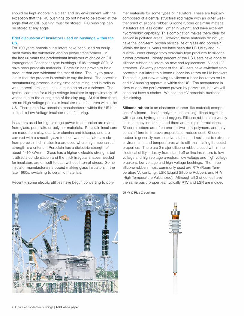
25 kV O Plus C bushing

ABB white paper | Future of condenser bushings 5
whereas HTV is extruded giving HTV more versatility during the manufacturing process by not being limited to molds. When choosing a product utilizing silicone rubbers the application and environment should be considered. If we were to grade the performance of RTV, LSR, and HTV on products being used within the electrical industry we would see RTV as the lowest grade and HTV as the highest grade. Users should research the application and choose the proper product with the proper silicone rubber to be used and also note that how the rubbers are processed is critical to the end product. Silicone rubbers maintain their mechanical properties over a wide range of temperatures and the presence of methyl-groups in silicone rubbers makes these materials extremely hydrophobic. Silicone rubbers are perfect for low voltage and high voltage insulators in contaminated environments with less routine maintenance. Sili-cone rubbers very seldom need to be cleaned reducing routine maintenance, unnecessary outages, and flashovers.
Epoxy is the cured end product of epoxy resins. Epoxy is used in some cast condenser bushings and has the advantages of being oil free and can be versatile to making dimensional adjust-ments for replacement application fit in a short period of time. Although epoxy is a polymer type of product it does not have the hydrophobic properties that silicone rubbers contain such as RTV, LSR, and HTV. Epoxy type bushings should not be considered when applying in highly contaminated environments.
Conclusion on Insulator MaterialsAlthough we know porcelain is a proven product there are many cons such as safety of porcelain shards during an event, security concerns of vandalism, and terrorist attacks. Silicone and Epoxy type materials help prevent further damage to other equipment and to personnel when there is an event or attack on the system. The benefit of the hydrophobic properties of silicone rubbers to contaminants is a tremendous solution to flashover and high cost of routine cleaning.
Managing the risks The move to Resin Type Condenser Core Condensers with Silicone Rubber Insulator could help manage the risk to the grid and reduce failures with less maintenance. If your company has experienced any field issues listed below with Oil Impregnated Paper Condenser Bushings utilizing Porcelain Insulators you should consider Resin Type Condenser Cores with Silicone Insulators.
− Bushings catching on fire or supplemental to an existing fire? − Porcelain shards external to transformer damaging other
equipment or people? − Porcelain shards damaging transformer internals? − Seismic events? − Bushings shortened life expectancy due to moisture ingress? − Bushings shortened life expectancy due to gas bubble evo-
lution? − Bushing failure due to external flashover due to high contami-
nation? − Bushings with oil leaks and create further concerns or costly
environmental cleanup? − Bushings damaged due to vandalism or terrorism?
The advantages and benefits of Resin Type Condenser Core Condensers with Silicone Rubber Insulator Bushings:
− Safety – no porcelain shards during events − Apply at any angle 0 – 90 degrees − Fire retardant to prevent further damage of equipment − Hydrophobic – self cleaning properties and less maintenance
in contaminated environments − Lighter − Meet High Seismic Standards − Less routine maintenance − No oil leaks − Environmentally friendly − Less collateral damage − Security
Conclusion The US Electric Utility and Industrial End Users have a decision to move forward with the latest technologies available such as RIP and RIS utilizing Silicone Rubber Insulators to have a better, reliable, safe, and secure grid. Although the US industry percei-ves the technologies within this discussion as a new product, many of the products have been used in the rest of the world with thousands of products in service for over 25 years.
Within this paper we have presented several types of bushing condenser cores and types of insulator materials and user should complete their own research and understand that all ma-terials and designs are not the same within a finished product from the manufacturing of the condenser core to the materials used. The type of material, the quality of the material, how the material is processed, the design, the manufacturing, and appli-cation of the final product can have many different grades and perform differently in the field. The user must choose the best product to fit the need to manage the risk of the system and maintain that product per the manufacturers Product Installation and Maintenance Guidelines.
References: IEEE Standards C57.19.01.2000

Contact us
1ZU
A27
51-2
64
Note:We reserve the right to make technical changes or modify the contents of this document without prior notice. With regard to purchase orders, the agreed particulars shall prevail. ABB does not accept any responsibility whatsoever for potential errors or possible lack of information in this document.
We reserve all rights in this document and in the subject matter and illustrations contained therein. Any reproduction, disclosure to third parties or utilization of its content – in whole or in parts – is forbidden without ABB‘s prior written consent.
© Copyright 2014 ABB. All rights reserved.
ABB Inc.1133 South Cavalier Drive Alamo, Tennessee 38001, US Phone: +1 800 955 8399 +1 731 696 5561Fax: +1 731 696 5377
www.abb.com/electricalcomponents