Linear Bushing
74
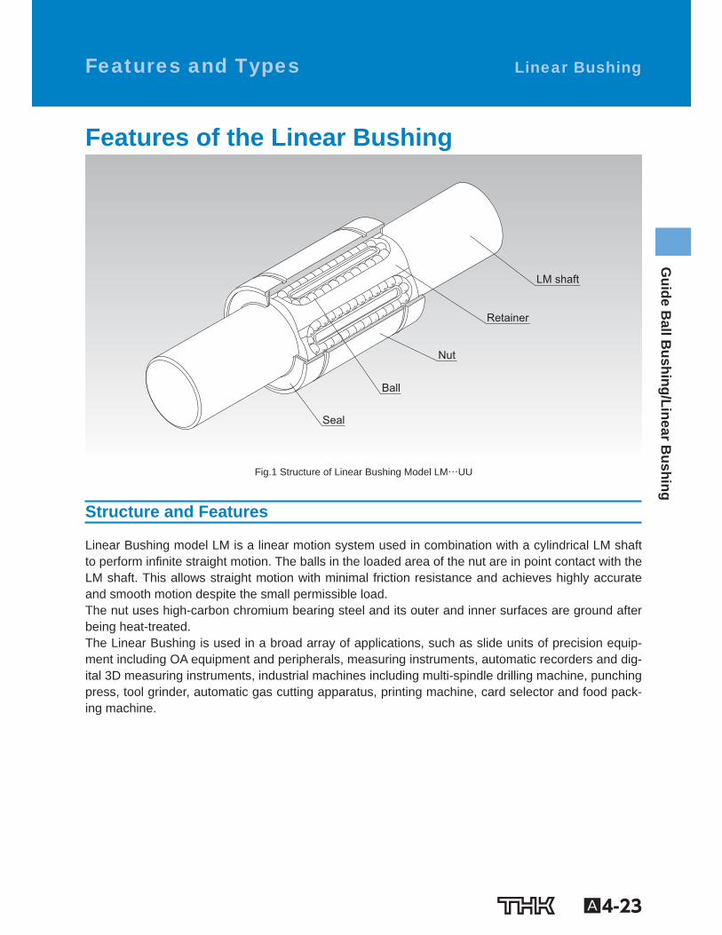
A4-23 Guide Ball Bushing/Linear Bushing Features and Types Linear Bushing Features of the Linear Bushing Nut LM shaft Retainer Ball Seal Fig.1 Structure of Linear Bushing Model LM…UU Structure and Features Linear Bushing model LM is a linear motion system used in combination with a cylindrical LM shaft to perform inÝnite straight motion. The balls in the loaded area of the nut are in point contact with the LM shaft. This allows straight motion with minimal friction resistance and achieves highly accurate and smooth motion despite the small permissible load. The nut uses high-carbon chromium bearing steel and its outer and inner surfaces are ground after being heat-treated. The Linear Bushing is used in a broad array of applications, such as slide units of precision equip- ment including OA equipment and peripherals, measuring instruments, automatic recorders and dig- ital 3D measuring instruments, industrial machines including multi-spindle drilling machine, punching press, tool grinder, automatic gas cutting apparatus, printing machine, card selector and food pack- ing machine.
-
Upload
thk-america-inc -
Category
Business
-
view
1.034 -
download
7
description
Transcript of Linear Bushing
A4-23
Guide B
all Bushing/Linear B
ushing Features and Types Linear Bushing
Features of the Linear Bushing
Nut
LM shaft
Retainer
Ball
Seal
Fig.1 Structure of Linear Bushing Model LM…UU
Structure and Features
Linear Bushing model LM is a linear motion system used in combination with a cylindrical LM shaft to perform in nite straight motion. The balls in the loaded area of the nut are in point contact with the LM shaft. This allows straight motion with minimal friction resistance and achieves highly accurate and smooth motion despite the small permissible load. The nut uses high-carbon chromium bearing steel and its outer and inner surfaces are ground after being heat-treated. The Linear Bushing is used in a broad array of applications, such as slide units of precision equip-ment including OA equipment and peripherals, measuring instruments, automatic recorders and dig-ital 3D measuring instruments, industrial machines including multi-spindle drilling machine, punching press, tool grinder, automatic gas cutting apparatus, printing machine, card selector and food pack-ing machine.
A4-24
[Interchangeability] Since the dimensional tolerances of the Linear Bush’s components are standardized, they are inter-changeable. The LM shaft is machined through cylindrical grinding, which can easily be performed, and it allows highly accurate tting clearance to be achieved.
[Highly Accurate Retainer Plate] Since the retainer, which guides three to eight rows of balls, is integrally molded, it is capable of ac-curately guiding the balls in the traveling direction and achieving stable running accuracy. Small-diameter types use integrally molded retainers made of synthetic resin. It reduces noise gen-erated during operation and allows for superb lubrication.
[Wide Array of Types] A wide array of types are available, such as standard type, clearance-adjustable type, open type, long type and anged linear bushing, allowing the user to select a type that meets the intended use.
A4-25
Guide B
all Bushing/Linear B
ushing
Types of the Linear Ball Bushing Types and Features
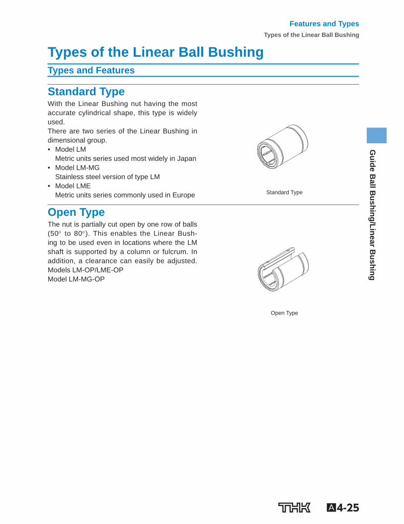
Standard Type With the Linear Bushing nut having the most accurate cylindrical shape, this type is widely used. There are two series of the Linear Bushing in dimensional group. • Model LM
Metric units series used most widely in Japan • Model LM-MG
Stainless steel version of type LM • Model LME
Metric units series commonly used in Europe
Standard Type
Open Type The nut is partially cut open by one row of balls (50 to 80 ). This enables the Linear Bush-ing to be used even in locations where the LM shaft is supported by a column or fulcrum. In addition, a clearance can easily be adjusted. Models LM-OP/LME-OP Model LM-MG-OP
Open Type
Features and TypesTypes of the Linear Ball Bushing
A4-26
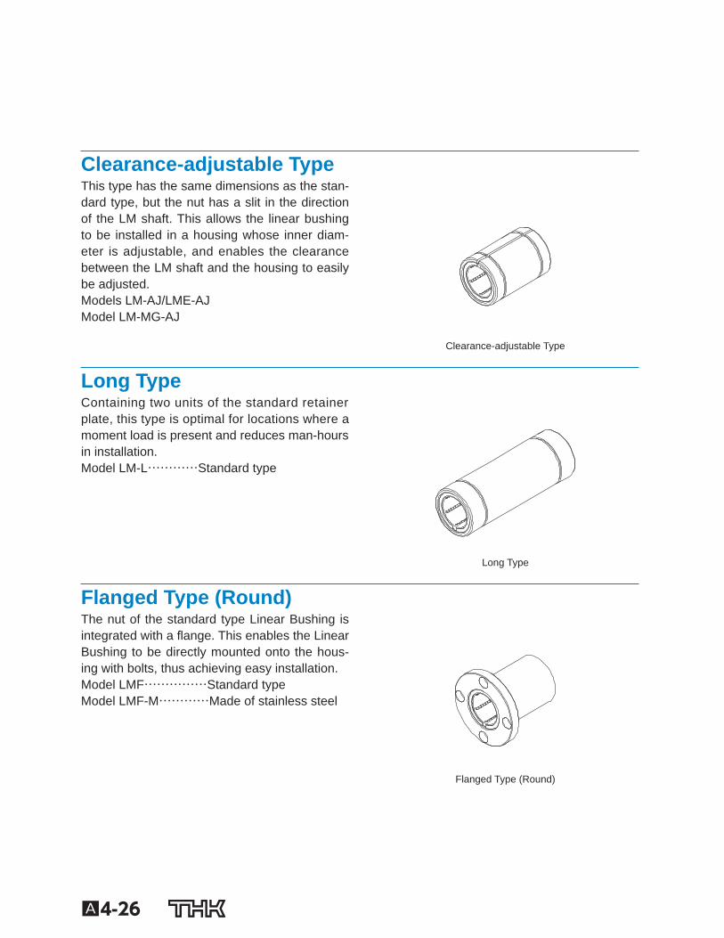
Clearance-adjustable Type This type has the same dimensions as the stan-dard type, but the nut has a slit in the direction of the LM shaft. This allows the linear bushing to be installed in a housing whose inner diam-eter is adjustable, and enables the clearance between the LM shaft and the housing to easily be adjusted. Models LM-AJ/LME-AJ Model LM-MG-AJ
Clearance-adjustable Type
Long Type Containing two units of the standard retainerplate, this type is optimal for locations where amoment load is present and reduces man-hours in installation.Model LM-L…………Standard type
Long Type
Flanged Type (Round) The nut of the standard type Linear Bushing is integrated with a ange. This enables the Linear Bushing to be directly mounted onto the hous-ing with bolts, thus achieving easy installation. Model LMF……………Standard type Model LMF-M…………Made of stainless steel
Flanged Type (Round)
A4-27
Guide B
all Bushing/Linear B
ushing
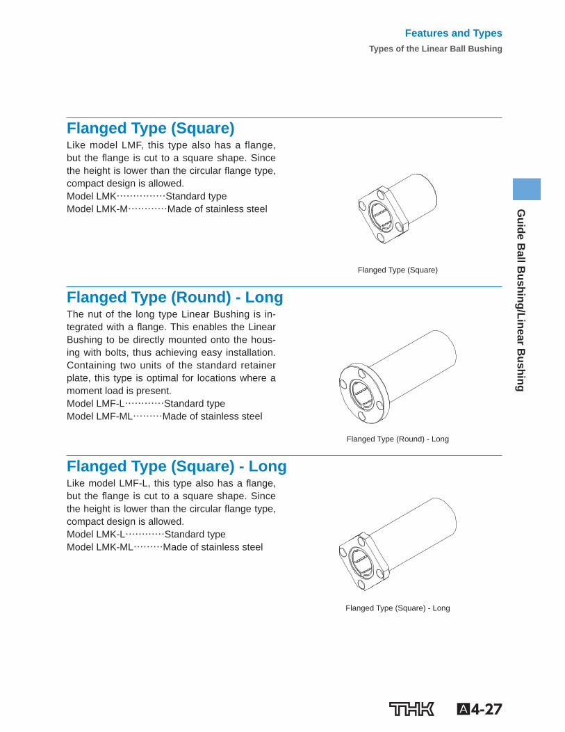
Flanged Type (Square) Like model LMF, this type also has a flange, but the ange is cut to a square shape. Since the height is lower than the circular ange type, compact design is allowed. Model LMK……………Standard type Model LMK-M…………Made of stainless steel
Flanged Type (Square)
Flanged Type (Round) - Long The nut of the long type Linear Bushing is in-tegrated with a ange. This enables the Linear Bushing to be directly mounted onto the hous-ing with bolts, thus achieving easy installation. Containing two units of the standard retainer plate, this type is optimal for locations where a moment load is present. Model LMF-L…………Standard type Model LMF-ML………Made of stainless steel
Flanged Type (Round) - Long
Flanged Type (Square) - Long Like model LMF-L, this type also has a ange, but the ange is cut to a square shape. Since the height is lower than the circular ange type, compact design is allowed. Model LMK-L…………Standard type Model LMK-ML………Made of stainless steel
Flanged Type (Square) - Long
Features and TypesTypes of the Linear Ball Bushing
A4-28
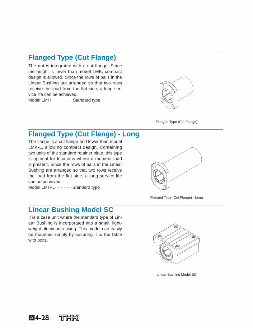
Flanged Type (Cut Flange) The nut is integrated with a cut flange. Since the height is lower than model LMK, compact design is allowed. Since the rows of balls in the Linear Bushing are arranged so that two rows receive the load from the at side, a long ser-vice life can be achieved. Model LMH……………Standard type
Flanged Type (Cut Flange)
Flanged Type (Cut Flange) - Long The ange is a cut ange and lower than model LMK-L, allowing compact design. Containing two units of the standard retainer plate, this type is optimal for locations where a moment load is present. Since the rows of balls in the Linear Bushing are arranged so that two rows receive the load from the flat side, a long service life can be achieved. Model LMH-L…………Standard type
Flanged Type (Cut Flange) - Long
Linear Bushing Model SC It is a case unit where the standard type of Lin-ear Bushing is incorporated into a small, light-weight aluminum casing. This model can easily be mounted simply by securing it to the table with bolts.
Linear Bushing Model SC
A4-29
Guide B
all Bushing/Linear B
ushing
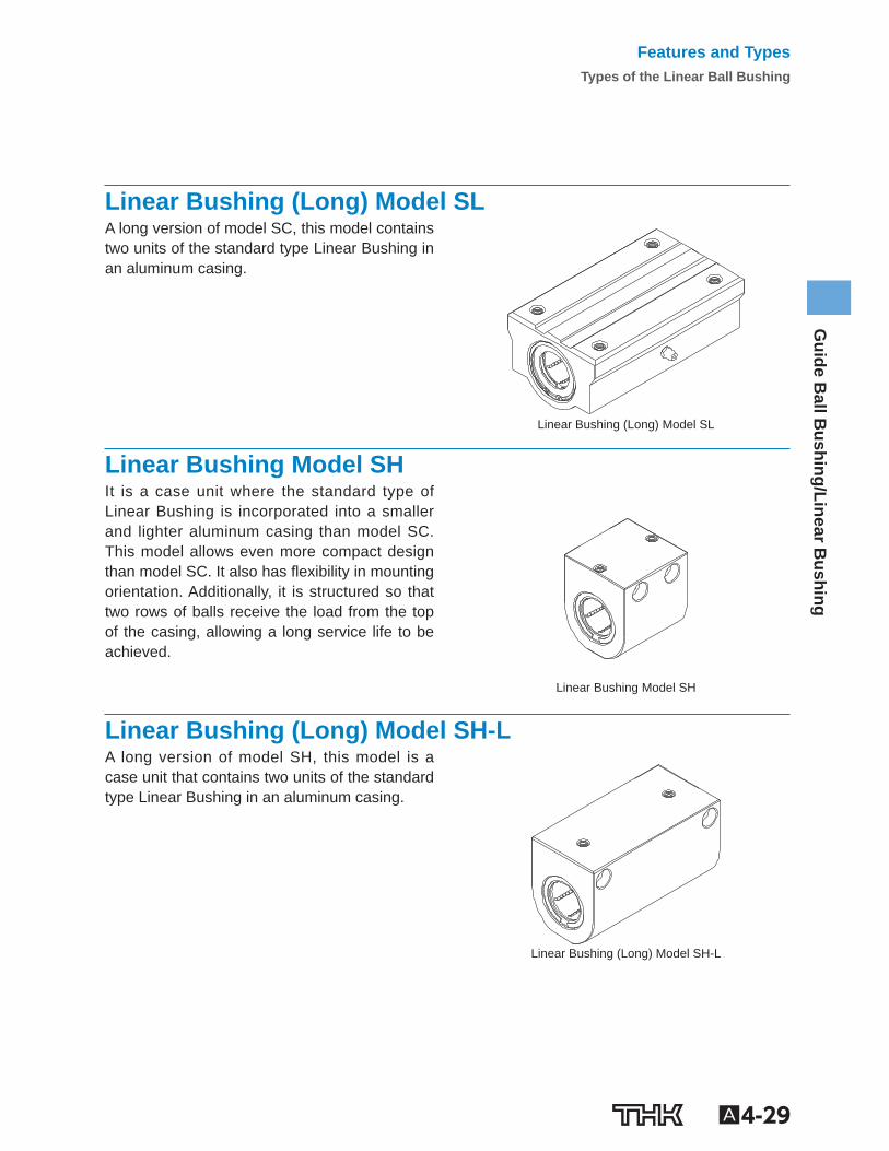
Linear Bushing (Long) Model SL A long version of model SC, this model contains two units of the standard type Linear Bushing in an aluminum casing.
Linear Bushing (Long) Model SL
Linear Bushing Model SH It is a case unit where the standard type of Linear Bushing is incorporated into a smaller and lighter aluminum casing than model SC. This model allows even more compact design than model SC. It also has exibility in mounting orientation. Additionally, it is structured so that two rows of balls receive the load from the top of the casing, allowing a long service life to be achieved.
Linear Bushing Model SH
Linear Bushing (Long) Model SH-L A long version of model SH, this model is a case unit that contains two units of the standard type Linear Bushing in an aluminum casing.
Linear Bushing (Long) Model SH-L
Features and TypesTypes of the Linear Ball Bushing
A4-30
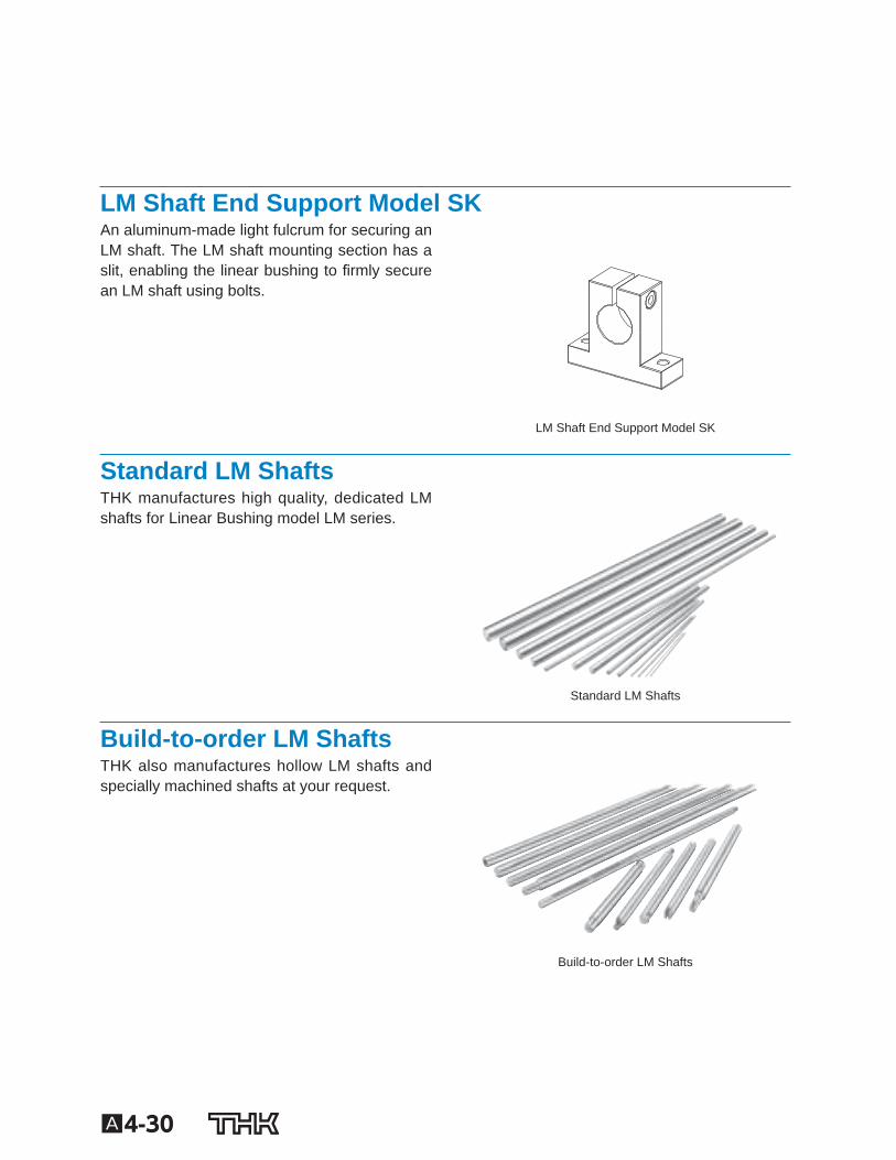
LM Shaft End Support Model SK An aluminum-made light fulcrum for securing an LM shaft. The LM shaft mounting section has a slit, enabling the linear bushing to rmly secure an LM shaft using bolts.
LM Shaft End Support Model SK
Standard LM Shafts THK manufactures high quality, dedicated LM shafts for Linear Bushing model LM series.
Standard LM Shafts
Build-to-order LM Shafts THK also manufactures hollow LM shafts and specially machined shafts at your request.
Build-to-order LM Shafts
A4-31
Guide B
all Bushing/Linear B
ushing
Features and TypesTypes of the Linear Ball Bushing
A4-32
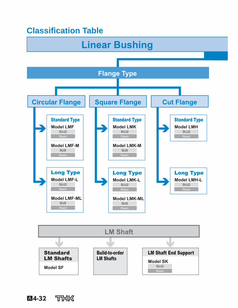
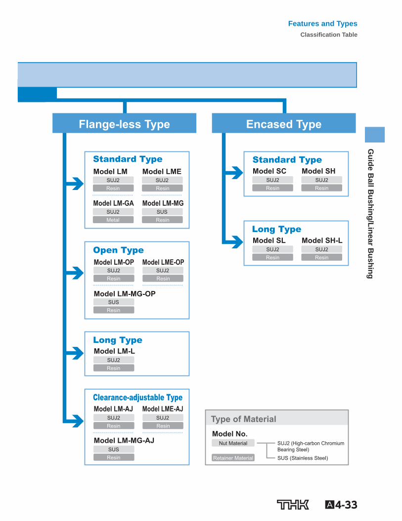
Classi cation Table
Linear Bushing
Flange Type
Circular Flange Square Flange Cut Flange
Long TypeModel LMF-L
Resin
Model LMF-ML
Resin
Standard TypeModel LMF
Resin
Model LMF-M
Resin
Long TypeModel LMK-L
Resin
Model LMK-ML
Resin
Standard TypeModel LMK
Resin
Model LMK-M
Resin
Long TypeModel LMH-L
Resin
Standard TypeModel LMH
Resin
LM Shaft
Model SK
Resin
LM Shaft End Support Build-to-orderLM Shafts
Model SF
StandardLM Shafts
SUJ2
SUJ2
SUS
SUJ2
SUS
SUJ2
SUS
SUJ2
SUS
SUJ2
SUJ2
A4-33
Guide B
all Bushing/Linear B
ushing
Flange-less Type Encased Type
Standard TypeModel SC
Resin
Model SH
Resin
Long TypeModel SL
Resin
Model SH-L
ResinOpen TypeModel LM-OP
Resin
Model LM-MG-OP
Resin
Model LME-OP
Resin
Clearance-adjustable TypeModel LM-AJ
Resin
Model LM-MG-AJ
Resin
Model LME-AJ
Resin
Model LM-L
Resin
Long Type
Standard TypeModel LM
Resin
Model LM-GA
Metal
Model LME
Resin
Model LM-MG
Resin
Nut Material SUJ2 (High-carbon Chromium Bearing Steel)
Model No.
Retainer Material SUS (Stainless Steel)
Type of Material
SUJ2 SUJ2
SUJ2 SUJ2
SUJ2
SUJ2
SUJ2
SUJ2
SUS
SUJ2
SUJ2
SUJ2
SUS
SUJ2 SUS
Features and TypesClassi cation Table
A4-34
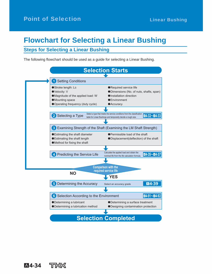
Flowchart for Selecting a Linear Bushing Steps for Selecting a Linear Bushing
The following owchart should be used as a guide for selecting a Linear Bushing.
Comparison with the required service life
Setting Conditions
�Stroke length: LS
�Velocity: V�Magnitude of the applied load: W�Mounting space�Operating frequency (duty cycle)
�Required service life�Dimensions (No. of nuts, shafts, span)�Installation direction�Environment�Accuracy
Selecting a Type
Examining Strength of the Shaft (Examining the LM Shaft Strength)
�Estimating the shaft diameter�Estimating the shaft length�Method for fixing the shaft
�Permissible load of the shaft�Displacement(deflection) of the shaft
Calculate the applied load and obtain thenominal life from the life calculation formula.Predicting the Service Life
Selection Starts
Selection Completed
Determining the Accuracy
Selection According to the Environment
�Determining a lubricant�Determining a lubrication method
�Determining a surface treatment�Designing contamination protection
Select a type that meets the service conditions from the classification table for Linear Bushings and temporarily decide a rough size.
NOYES
Select an accuracy grade
4
3
2
1
5
6
Linear Bushing Point of Selection
A4-32~A4-33
A4-35~A4-37
A4-91~A4-92
A4-39
A4-35
Guide B
all Bushing/Linear B
ushing
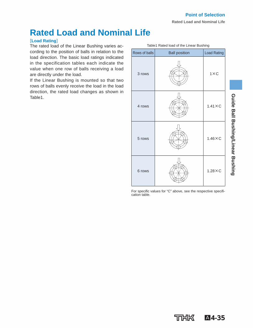
Rated Load and Nominal Life [Load Rating] The rated load of the Linear Bushing varies ac-cording to the position of balls in relation to the load direction. The basic load ratings indicated in the specification tables each indicate the value when one row of balls receiving a load are directly under the load. If the Linear Bushing is mounted so that two rows of balls evenly receive the load in the load direction, the rated load changes as shown in Table1 .
Table1 Rated load of the Linear Bushing
Rows of balls Ball position Load Rating
3 rows
1×C
4 rows
1.41×C
5 rows
1.46×C
6 rows
1.28×C
For speci c values for “C” above, see the respective speci -cation table.
Point of SelectionRated Load and Nominal Life
A4-36
[Calculating the Nominal Life] The nominal life of the Linear Bushing is obtained using the following equation.
L = • 3
50 C PC
fH•fT•fC
fW
L : Nominal life (km) C : Basic dynamic load rating (N) P C : Calculated load (N) f T : Temperature factor (see Fig.2 on A4-37 ) f C : Contact factor (see Table2 on A4-37 ) f W : Load factor (see Table3 on A4-37 ) f H : Hardness factor (see Fig.1 )
When a Moment Load is Applied to a Single Nut or Two Nuts in Close Contact with Each Other
When a moment load is applied to a single nut or two nuts in close contact with each other, calculate the equivalent radial load at the time the moment is applied.
Pu = K•M P u : Equivalent radial load (N) (with a moment applied) K : Equivalent factors (see Table4 to Table6 on A4-38 ) M : Applied moment (N-mm) However, “P u ” is assumed to be within the basic static load rating (C 0 ).
When a Moment Load and a Radial Load are Simultaneously Applied When a moment and a radial load are applied simultaneously, calculate the service life based on the sum of the radial load and the equivalent radial load.
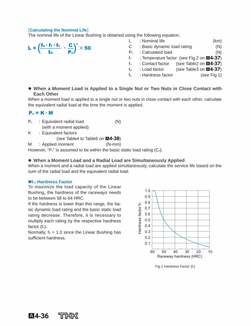
f H : Hardness Factor To maximize the load capacity of the Linear Bushing, the hardness of the raceways needs to be between 58 to 64 HRC. If the hardness is lower than this range, the ba-sic dynamic load rating and the basic static load rating decrease. Therefore, it is necessary to multiply each rating by the respective hardness factor (f H ). Normally, f H = 1.0 since the Linear Bushing has suf cient hardness.
Raceway hardness (HRC)
Har
dnes
s fa
ctor
fH
1.0 0.9 0.8 0.7 0.6 0.5 0.4 0.3 0.2 0.1
60 50 40 30 20 10
Fig.1 Hardness Factor (f H )
A4-37
Guide B
all Bushing/Linear B
ushing
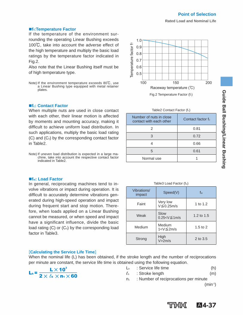
f T :Temperature Factor If the temperature of the environment sur-rounding the operating Linear Bushing exceeds 100℃, take into account the adverse effect of the high temperature and multiply the basic load ratings by the temperature factor indicated in Fig.2 . Also note that the Linear Bushing itself must be of high temperature type.
Note) If the environment temperature exceeds 80℃, use
a Linear Bushing type equipped with metal retainer plates. Raceway temperature (℃)
Tem
pera
ture
fact
or fT
100 150 200
1.0
0.9
0.8
0.7
0.6
0.5
Fig.2 Temperature Factor (f T )
f C : Contact Factor When multiple nuts are used in close contact with each other, their linear motion is affected by moments and mounting accuracy, making it dif cult to achieve uniform load distribution. In such applications, multiply the basic load rating (C) and (C 0 ) by the corresponding contact factor in Table2 .
Note) If uneven load distribution is expected in a large ma-
chine, take into account the respective contact factor indicated in Table2 .
Table2 Contact Factor (f C )
Number of nuts in closecontact with each other Contact factor f C
2 0.81
3 0.72
4 0.66
5 0.61
Normal use 1
f W : Load Factor In general, reciprocating machines tend to in-volve vibrations or impact during operation. It is dif cult to accurately determine vibrations gen-erated during high-speed operation and impact during frequent start and stop motion. There-fore, when loads applied on a Linear Bushing cannot be measured, or when speed and impact have a significant influence, divide the basic load rating (C) or (C 0 ) by the corresponding load factor in Table3 .
Table3 Load Factor (f W )
Vibrations/impact Speed(V) f W
Faint Very low V≦0.25m/s 1 to 1.2
Weak Slow 0.25<V≦1m/s 1.2 to 1.5
Medium Medium 1<V≦2m/s 1.5 to 2
Strong High V>2m/s 2 to 3.5
[Calculating the Service Life Time] When the nominal life (L) has been obtained, if the stroke length and the number of reciprocations per minute are constant, the service life time is obtained using the following equation.
60 n1ℓS2
103 L Lh =
L h : Service life time (h) ℓ S : Stroke length (m) n 1 : Number of reciprocations per minute (min -1 )
Point of SelectionRated Load and Nominal Life
A4-38
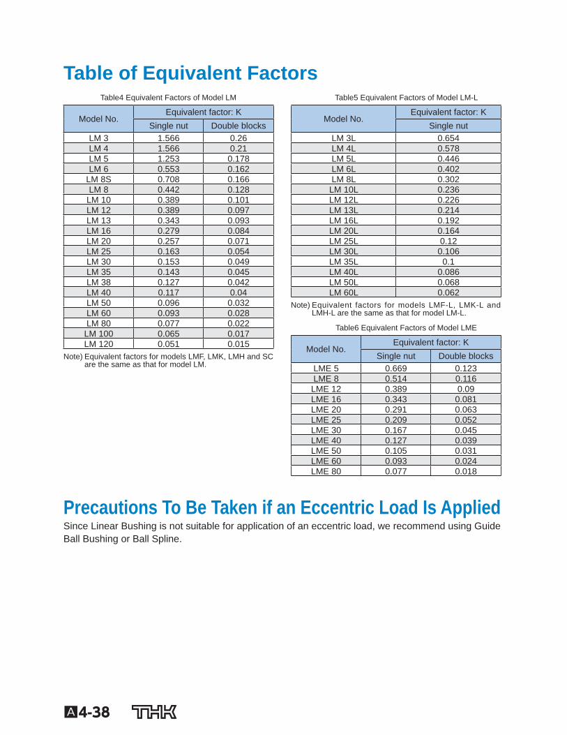
Table of Equivalent Factors Table4 Equivalent Factors of Model LM
Model No. Equivalent factor: K
Single nut Double blocks LM 3 1.566 0.26 LM 4 1.566 0.21 LM 5 1.253 0.178 LM 6 0.553 0.162
LM 8S 0.708 0.166 LM 8 0.442 0.128
LM 10 0.389 0.101 LM 12 0.389 0.097 LM 13 0.343 0.093 LM 16 0.279 0.084 LM 20 0.257 0.071 LM 25 0.163 0.054 LM 30 0.153 0.049 LM 35 0.143 0.045 LM 38 0.127 0.042 LM 40 0.117 0.04 LM 50 0.096 0.032 LM 60 0.093 0.028 LM 80 0.077 0.022
LM 100 0.065 0.017 LM 120 0.051 0.015
Note) Equivalent factors for models LMF, LMK, LMH and SC are the same as that for model LM.
Table5 Equivalent Factors of Model LM-L
Model No. Equivalent factor: K
Single nut LM 3L 0.654 LM 4L 0.578 LM 5L 0.446 LM 6L 0.402 LM 8L 0.302 LM 10L 0.236 LM 12L 0.226 LM 13L 0.214 LM 16L 0.192 LM 20L 0.164 LM 25L 0.12 LM 30L 0.106 LM 35L 0.1 LM 40L 0.086 LM 50L 0.068 LM 60L 0.062
Note) Equivalent factors for models LMF-L, LMK-L and LMH-L are the same as that for model LM-L.
Table6 Equivalent Factors of Model LME
Model No. Equivalent factor: K
Single nut Double blocks LME 5 0.669 0.123 LME 8 0.514 0.116 LME 12 0.389 0.09 LME 16 0.343 0.081 LME 20 0.291 0.063 LME 25 0.209 0.052 LME 30 0.167 0.045 LME 40 0.127 0.039 LME 50 0.105 0.031 LME 60 0.093 0.024 LME 80 0.077 0.018
Precautions To Be Taken if an Eccentric Load Is Applied Since Linear Bushing is not suitable for application of an eccentric load, we recommend using Guide Ball Bushing or Ball Spline.
A4-39
Guide B
all Bushing/Linear B
ushing
Accuracy Standards [Linear Bushing] The accuracy of the Linear Bushing in inscribed bore diameter, outer diameter, width and eccentric-ity is described in the corresponding speci cation table. The accuracy of mode LM in inscribed bore diameter and eccentricity is classi ed into high accuracy grade (no symbol) and precision grade (P). (Accuracy symbol is expressed at the end of the model number.) The accuracy of clearance-adjustable types (-AJ) and open types (-OP) in inscribed bore diameter and outer diameter indicates the value before division.
Point of SelectionAccuracy Standards
A4-40 To download a desired data, search for the corresponding model number in the Technical site. https://tech.thk.com
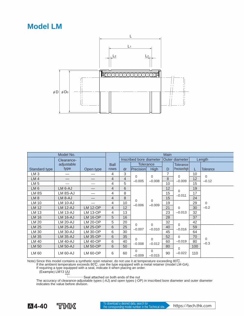
Model LM
L
L2 L2
L1
φ D0φ D
Model No. Main Clearance-
adjustabletype
Inscribed bore diameter Outer diameter Length Ball
rows Tolerance Tolerance
Precision/high
Standard type Open type dr Precision High D L Tolerance LM 3 — — 4 3
0 –0.005
0 –0.008
7 0
–0.009
10 0
–0.12
LM 4 — — 4 4 8 12 LM 5 — — 4 5 10 15 LM 6 LM 6-AJ — 4 6
0 –0.006
0 –0.009
12 0
–0.011
19
0 –0.2
LM 8S LM 8S-AJ — 4 8 15 17 LM 8 LM 8-AJ — 4 8 15 24 LM 10 LM 10-AJ — 4 10 19
0 –0.013
29 LM 12 LM 12-AJ LM 12-OP 4 12 21 30 LM 13 LM 13-AJ LM 13-OP 4 13 23 32 LM 16 LM 16-AJ LM 16-OP 5 16 28 37 LM 20 LM 20-AJ LM 20-OP 5 20
0 –0.007
0 –0.010
32 0
–0.016
42 LM 25 LM 25-AJ LM 25-OP 6 25 40 59
0 –0.3
LM 30 LM 30-AJ LM 30-OP 6 30 45 64 LM 35 LM 35-AJ LM 35-OP 6 35
0 –0.008
0 –0.012
52 0 –0.019
70 LM 40 LM 40-AJ LM 40-OP 6 40 60 80 LM 50 LM 50-AJ LM 50-OP 6 50 80 0
–0.022
100
LM 60 LM 60-AJ LM 60-OP 6 60 0 –0.009
0 –0.015 90 110
Note) Since this model contains a synthetic resin retainer, do not use it at temperature exceeding 80℃. If the ambient temperature exceeds 80℃, use the type equipped with a metal retainer (model LM-GA). If requiring a type equipped with a seal, indicate it when placing an order.
Seal attached on both ends of the nut (Example) LM13 UU
The accuracy of clearance-adjustable types (-AJ) and open types (-OP) in inscribed bore diameter and outer diameter indicates the value before division.
A4-41
Guide B
all Bushing/Linear B
ushing
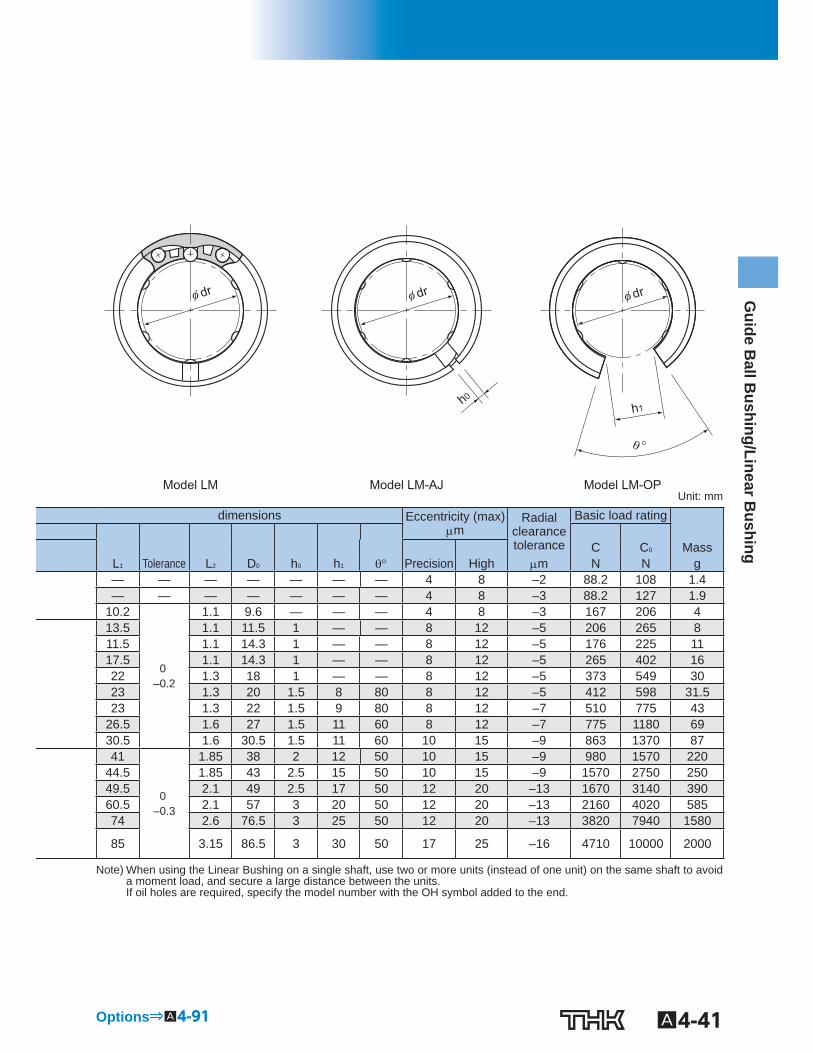
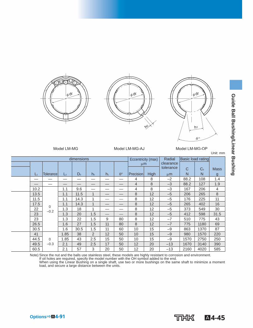
Model LM-AJ Model LM-OP Model LM
h0
φ dr φ dr φ dr
h1
θ °
Unit: mm
dimensions Eccentricity (max) m
Radial clearance tolerance
Basic load rating C C 0 Mass L 1 Tolerance L 2 D 0 h 0 h 1 Precision High m N N g — — — — — — — 4 8 –2 88.2 108 1.4 — — — — — — — 4 8 –3 88.2 127 1.9
10.2
0 –0.2
1.1 9.6 — — — 4 8 –3 167 206 4 13.5 1.1 11.5 1 — — 8 12 –5 206 265 8 11.5 1.1 14.3 1 — — 8 12 –5 176 225 11 17.5 1.1 14.3 1 — — 8 12 –5 265 402 16 22 1.3 18 1 — — 8 12 –5 373 549 30 23 1.3 20 1.5 8 80 8 12 –5 412 598 31.5 23 1.3 22 1.5 9 80 8 12 –7 510 775 43
26.5 1.6 27 1.5 11 60 8 12 –7 775 1180 69 30.5 1.6 30.5 1.5 11 60 10 15 –9 863 1370 87 41
0 –0.3
1.85 38 2 12 50 10 15 –9 980 1570 220 44.5 1.85 43 2.5 15 50 10 15 –9 1570 2750 250 49.5 2.1 49 2.5 17 50 12 20 –13 1670 3140 390 60.5 2.1 57 3 20 50 12 20 –13 2160 4020 585 74 2.6 76.5 3 25 50 12 20 –13 3820 7940 1580
85 3.15 86.5 3 30 50 17 25 –16 4710 10000 2000
Note) When using the Linear Bushing on a single shaft, use two or more units (instead of one unit) on the same shaft to avoid a moment load, and secure a large distance between the units. If oil holes are required, specify the model number with the OH symbol added to the end.
Options⇒A4-91
A4-42 To download a desired data, search for the corresponding model number in the Technical site. https://tech.thk.com
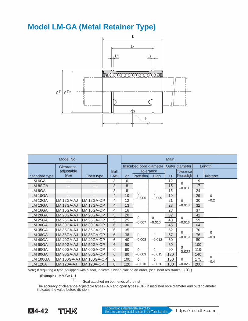
Model LM-GA (Metal Retainer Type)
L
L2 L2
L1
φ D0φ D
d0
Model No. Main
Clearance-adjustable
type
Inscribed bore diameter Outer diameter Length Ball
rows Tolerance Tolerance
Precision/high
Standard type Open type dr Precision High D L Tolerance LM 6GA — — 3 6
0 –0.006
0 –0.009
12 0
–0.011
19
0 –0.2
LM 8SGA — — 3 8 15 17 LM 8GA — — 3 8 15 24 LM 10GA — — 4 10 19
0 –0.013
29 LM 12GA LM 12GA-AJ LM 12GA-OP 4 12 21 30 LM 13GA LM 13GA-AJ LM 13GA-OP 4 13 23 32 LM 16GA LM 16GA-AJ LM 16GA-OP 4 16 28 37 LM 20GA LM 20GA-AJ LM 20GA-OP 5 20
0 –0.007
0 –0.010
32 0
–0.016
42 LM 25GA LM 25GA-AJ LM 25GA-OP 5 25 40 59
0 –0.3
LM 30GA LM 30GA-AJ LM 30GA-OP 6 30 45 64 LM 35GA LM 35GA-AJ LM 35GA-OP 6 35
0 –0.008
0 –0.012
52 0
–0.019
70 LM 38GA LM 38GA-AJ LM 38GA-OP 6 38 57 76 LM 40GA LM 40GA-AJ LM 40GA-OP 6 40 60 80 LM 50GA LM 50GA-AJ LM 50GA-OP 6 50 80
0 –0.022
100 LM 60GA LM 60GA-AJ LM 60GA-OP 6 60 0
–0.009 0
–0.015 90 110
LM 80GA LM 80GA-AJ LM 80GA-OP 6 80 120 140 0
–0.4
LM 100GA LM 100GA-AJ LM 100GA-OP 6 100 0
–0.010 0
–0.020 150 0
–0.025 175
LM 120A LM 120A-AJ LM 120A-OP 8 120 180 200 Note) If requiring a type equipped with a seal, indicate it when placing an order. (seal heat resistance: 80℃.)
Seal attached on both ends of the nut (Example) LM50GA UU
The accuracy of clearance-adjustable types (-AJ) and open types (-OP) in inscribed bore diameter and outer diameter indicates the value before division.
A4-43
Guide B
all Bushing/Linear B
ushing
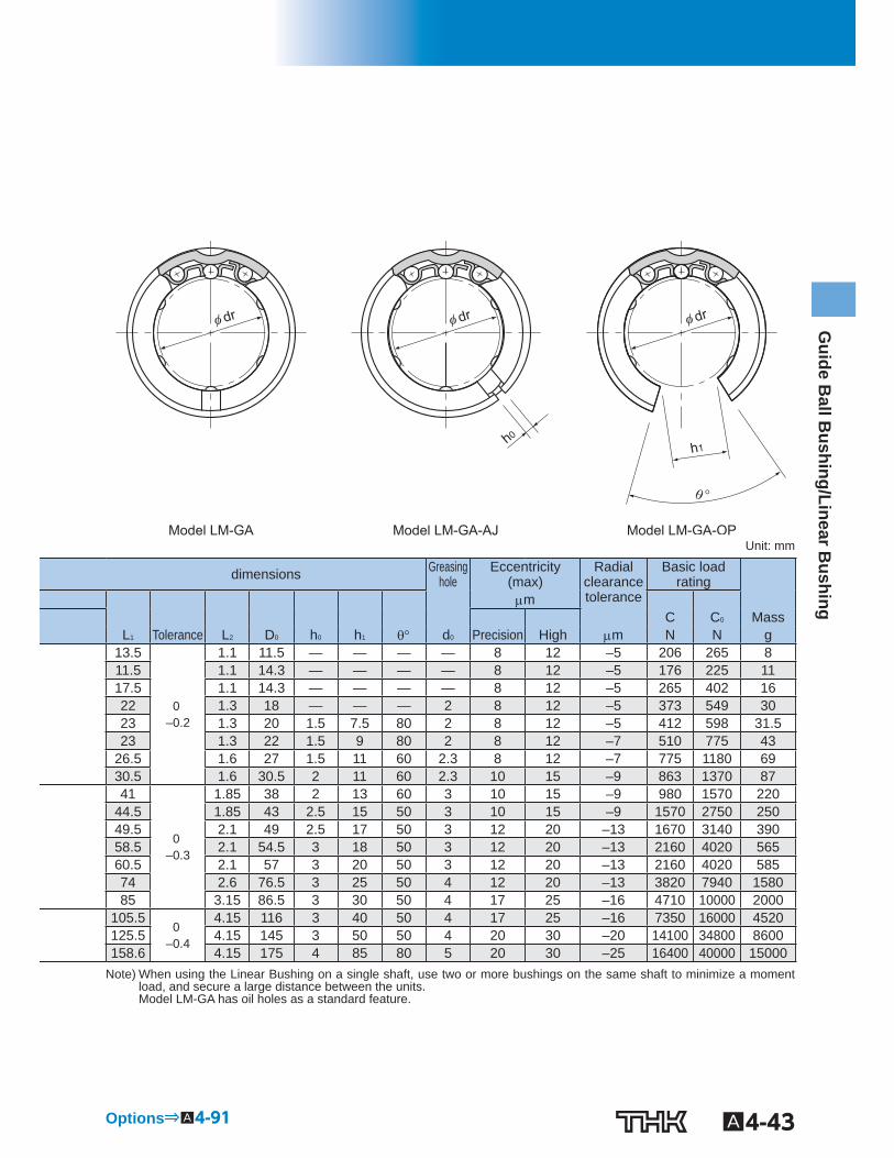
Model LM-GA-AJ Model LM-GA-OP Model LM-GA
φ dr φ dr φ dr
h1 h0
θ °
Unit: mm
dimensions Greasinghole
Eccentricity (max)
Radial clearance tolerance
Basic load rating
m C C 0 Mass L 1 Tolerance L 2 D 0 h 0 h 1 d 0 Precision High m N N g
13.5
0 –0.2
1.1 11.5 — — — — 8 12 –5 206 265 8 11.5 1.1 14.3 — — — — 8 12 –5 176 225 11 17.5 1.1 14.3 — — — — 8 12 –5 265 402 16 22 1.3 18 — — — 2 8 12 –5 373 549 30 23 1.3 20 1.5 7.5 80 2 8 12 –5 412 598 31.5 23 1.3 22 1.5 9 80 2 8 12 –7 510 775 43
26.5 1.6 27 1.5 11 60 2.3 8 12 –7 775 1180 69 30.5 1.6 30.5 2 11 60 2.3 10 15 –9 863 1370 87 41
0 –0.3
1.85 38 2 13 60 3 10 15 –9 980 1570 220 44.5 1.85 43 2.5 15 50 3 10 15 –9 1570 2750 250 49.5 2.1 49 2.5 17 50 3 12 20 –13 1670 3140 390 58.5 2.1 54.5 3 18 50 3 12 20 –13 2160 4020 565 60.5 2.1 57 3 20 50 3 12 20 –13 2160 4020 585 74 2.6 76.5 3 25 50 4 12 20 –13 3820 7940 1580 85 3.15 86.5 3 30 50 4 17 25 –16 4710 10000 2000
105.5 0
–0.4
4.15 116 3 40 50 4 17 25 –16 7350 16000 4520 125.5 4.15 145 3 50 50 4 20 30 –20 14100 34800 8600 158.6 4.15 175 4 85 80 5 20 30 –25 16400 40000 15000
Note) When using the Linear Bushing on a single shaft, use two or more bushings on the same shaft to minimize a moment load, and secure a large distance between the units. Model LM-GA has oil holes as a standard feature.
Options⇒A4-91
A4-44 To download a desired data, search for the corresponding model number in the Technical site. https://tech.thk.com
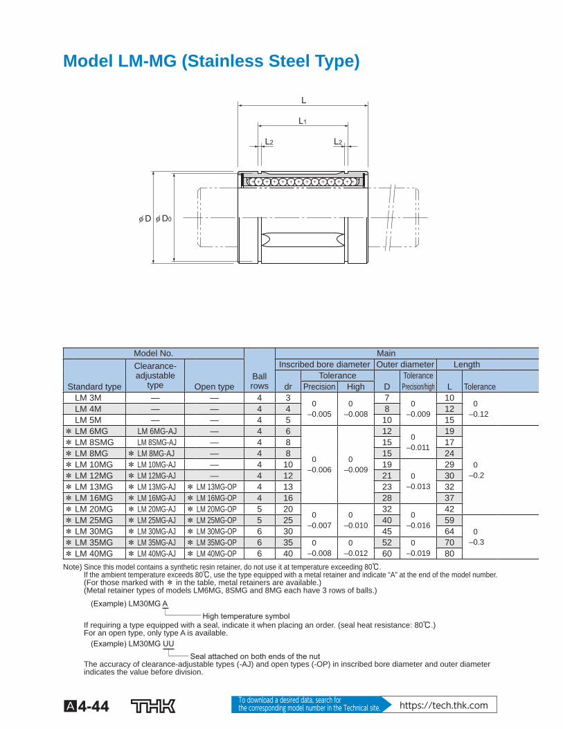
Model LM-MG (Stainless Steel Type)
L
L2 L2
L1
φ D0φ D
Model No. Main Clearance-adjustable
type
Inscribed bore diameter Outer diameter Length Ball rows
Tolerance Tolerance Standard type Open type dr Precision High D Precision/high L Tolerance LM 3M — — 4 3
0 –0.005
0 –0.008
7 0
–0.009
10 0
–0.12
LM 4M — — 4 4 8 12 LM 5M — — 4 5 10 15
* LM 6MG LM 6MG-AJ — 4 6
0 –0.006
0 –0.009
12 0
–0.011
19
0 –0.2
* LM 8SMG LM 8SMG-AJ — 4 8 15 17 * LM 8MG * LM 8MG-AJ — 4 8 15 24 * LM 10MG * LM 10MG-AJ — 4 10 19
0 –0.013
29 * LM 12MG * LM 12MG-AJ — 4 12 21 30 * LM 13MG * LM 13MG-AJ * LM 13MG-OP 4 13 23 32 * LM 16MG * LM 16MG-AJ * LM 16MG-OP 4 16 28 37 * LM 20MG * LM 20MG-AJ * LM 20MG-OP 5 20
0 –0.007
0 –0.010
32 0
–0.016
42 * LM 25MG * LM 25MG-AJ * LM 25MG-OP 5 25 40 59
0 –0.3
* LM 30MG * LM 30MG-AJ * LM 30MG-OP 6 30 45 64 * LM 35MG * LM 35MG-AJ * LM 35MG-OP 6 35 0
–0.008 0
–0.012 52 0
–0.019 70
* LM 40MG * LM 40MG-AJ * LM 40MG-OP 6 40 60 80 Note) Since this model contains a synthetic resin retainer, do not use it at temperature exceeding 80℃.
If the ambient temperature exceeds 80℃, use the type equipped with a metal retainer and indicate “A” at the end of the model number. (For those marked with * in the table, metal retainers are available.) (Metal retainer types of models LM6MG, 8SMG and 8MG each have 3 rows of balls.)
High temperature symbol (Example) LM30MG A
If requiring a type equipped with a seal, indicate it when placing an order. (seal heat resistance: 80℃.) For an open type, only type A is available.
Seal attached on both ends of the nut (Example) LM30MG UU
The accuracy of clearance-adjustable types (-AJ) and open types (-OP) in inscribed bore diameter and outer diameter indicates the value before division.
A4-45
Guide B
all Bushing/Linear B
ushing
Model LM-MG-AJ Model LM-MG-OP Model LM-MG
φ dr φ dr φ dr
h1 h0
θ °
Unit: mm
dimensions Eccentricity (max) m
Radial clearance tolerance
Basic load rating C C 0 Mass L 1 Tolerance L 2 D 0 h 0 h 1 Precision High m N N g — — — — — — — 4 8 –2 88.2 108 1.4 — — — — — — — 4 8 –3 88.2 127 1.9
10.2
0 –0.2
1.1 9.6 — — — 4 8 –3 167 206 4 13.5 1.1 11.5 1 — — 8 12 –5 206 265 8 11.5 1.1 14.3 1 — — 8 12 –5 176 225 11 17.5 1.1 14.3 1 — — 8 12 –5 265 402 16 22 1.3 18 1 — — 8 12 –5 373 549 30 23 1.3 20 1.5 — — 8 12 –5 412 598 31.5 23 1.3 22 1.5 9 80 8 12 –7 510 775 43
26.5 1.6 27 1.5 11 80 8 12 –7 775 1180 69 30.5 1.6 30.5 1.5 11 60 10 15 –9 863 1370 87 41
0 –0.3
1.85 38 2 12 50 10 15 –9 980 1570 220 44.5 1.85 43 2.5 15 50 10 15 –9 1570 2750 250 49.5 2.1 49 2.5 17 50 12 20 –13 1670 3140 390 60.5 2.1 57 3 20 50 12 20 –13 2160 4020 585
Note) Since the nut and the balls use stainless steel, these models are highly resistant to corrosion and environment. If oil holes are required, specify the model number with the OH symbol added to the end. When using the Linear Bushing on a single shaft, use two or more bushings on the same shaft to minimize a moment load, and secure a large distance between the units.
Options⇒A4-91
A4-46 To download a desired data, search for the corresponding model number in the Technical site. https://tech.thk.com
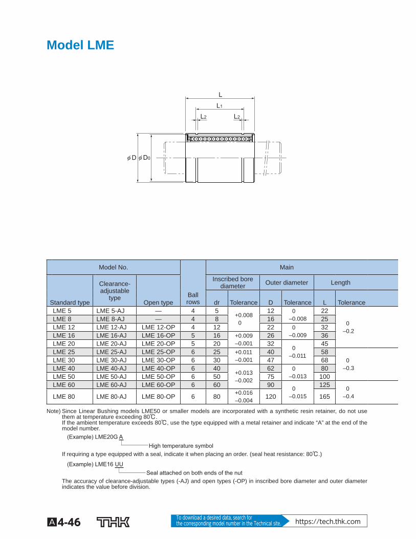
Model LME
L
L2 L2
L1
φ D0φ D
Model No. Main
Clearance-adjustable
type
Inscribed borediameter Outer diameter Length
Ball rows
Standard type Open type dr Tolerance D Tolerance L Tolerance
LME 5 LME 5-AJ — 4 5 +0.008
0
12 0 –0.008
22
0 –0.2
LME 8 LME 8-AJ — 4 8 16 25 LME 12 LME 12-AJ LME 12-OP 4 12 22 0
–0.009 32
LME 16 LME 16-AJ LME 16-OP 5 16 +0.009 –0.001
26 36 LME 20 LME 20-AJ LME 20-OP 5 20 32
0 –0.011
45 LME 25 LME 25-AJ LME 25-OP 6 25 +0.011
–0.001 40 58
0 –0.3
LME 30 LME 30-AJ LME 30-OP 6 30 47 68 LME 40 LME 40-AJ LME 40-OP 6 40
+0.013 –0.002
62 0 –0.013
80 LME 50 LME 50-AJ LME 50-OP 6 50 75 100 LME 60 LME 60-AJ LME 60-OP 6 60 90 0
–0.015
125 0 –0.4
LME 80 LME 80-AJ LME 80-OP 6 80 +0.016 –0.004 120 165
Note) Since Linear Bushing models LME50 or smaller models are incorporated with a synthetic resin retainer, do not use them at temperature exceeding 80℃. If the ambient temperature exceeds 80℃, use the type equipped with a metal retainer and indicate “A” at the end of the model number.
High temperature symbol (Example) LME20G A
If requiring a type equipped with a seal, indicate it when placing an order. (seal heat resistance: 80℃.)
Seal attached on both ends of the nut (Example) LME16 UU
The accuracy of clearance-adjustable types (-AJ) and open types (-OP) in inscribed bore diameter and outer diameter indicates the value before division.
A4-47
Guide B
all Bushing/Linear B
ushing
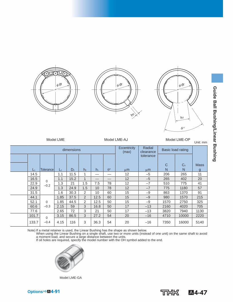
Model LME-AJ Model LME-OP Model LME
h0
φ dr φ dr φ dr
h1
θ °
Unit: mm
dimensions Eccentricity (max)
Radial clearance tolerance
Basic load rating
C C 0 Mass L 1 Tolerance L 2 D 0 h 0 h 1 m m N N g
14.5
0 –0.2
1.1 11.5 1 — — 12 –5 206 265 11 16.5 1.1 15.2 1 — — 12 –5 265 402 20 22.9 1.3 21 1.5 7.5 78 12 –7 510 775 41 24.9 1.3 24.9 1.5 10 78 12 –7 775 1180 57 31.5 1.6 30.3 2 10 60 15 –9 863 1370 91 44.1
0 –0.3
1.85 37.5 2 12.5 60 15 –9 980 1570 215 52.1 1.85 44.5 2 12.5 50 15 –9 1570 2750 325 60.6 2.15 59 3 16.8 50 17 –13 2160 4020 705 77.6 2.65 72 3 21 50 17 –13 3820 7940 1130 101.7 0
–0.4
3.15 86.5 3 27.2 54 20 –16 4710 10000 2220
133.7 4.15 116 3 36.3 54 20 –16 7350 16000 5140
Note) If a metal retainer is used, the Linear Bushing has the shape as shown below. When using the Linear Bushing on a single shaft, use two or more units (instead of one unit) on the same shaft to avoid a moment load, and secure a large distance between the units. If oil holes are required, specify the model number with the OH symbol added to the end.
Model LME-GA
Options⇒A4-91
A4-48 To download a desired data, search for the corresponding model number in the Technical site. https://tech.thk.com
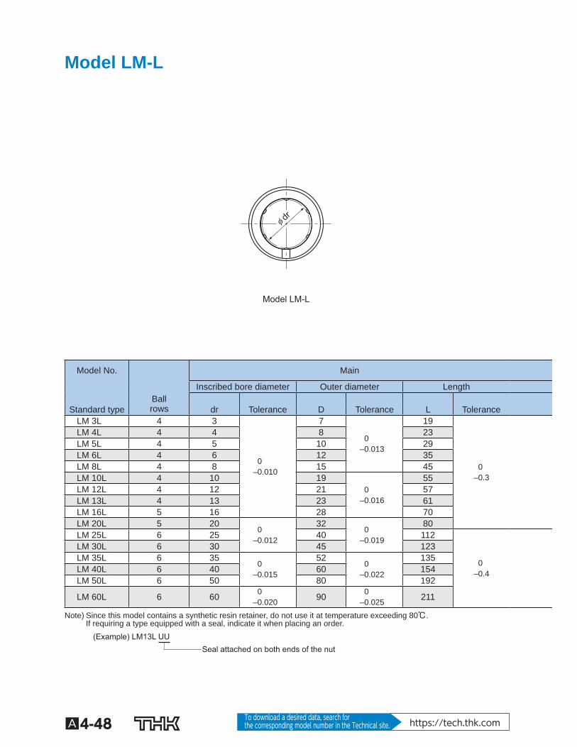
Model LM-L
Model LM-L
φ dr
Model No. Main
Inscribed bore diameter Outer diameter Length Ball
rows
Standard type dr Tolerance D Tolerance L Tolerance LM 3L 4 3
0 –0.010
7
0 –0.013
19
0 –0.3
LM 4L 4 4 8 23 LM 5L 4 5 10 29 LM 6L 4 6 12 35 LM 8L 4 8 15 45 LM 10L 4 10 19
0 –0.016
55 LM 12L 4 12 21 57 LM 13L 4 13 23 61 LM 16L 5 16 28 70 LM 20L 5 20
0 –0.012
32 0
–0.019
80 LM 25L 6 25 40 112
0 –0.4
LM 30L 6 30 45 123 LM 35L 6 35
0 –0.015
52 0
–0.022
135 LM 40L 6 40 60 154 LM 50L 6 50 80 192
LM 60L 6 60 0 –0.020 90 0
–0.025 211
Note) Since this model contains a synthetic resin retainer, do not use it at temperature exceeding 80℃. If requiring a type equipped with a seal, indicate it when placing an order.
Seal attached on both ends of the nut (Example) LM13L UU
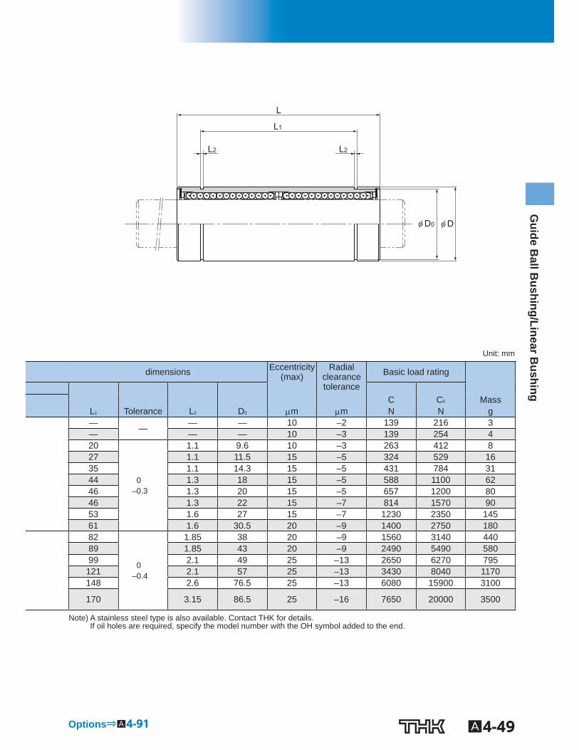
A4-49
Guide B
all Bushing/Linear B
ushing
L
φ D0 φ D
L2 L2
L1
Unit: mm
dimensions Eccentricity (max)
Radial clearance tolerance
Basic load rating
C C 0 Mass L 1 Tolerance L 2 D 0 m m N N g — — — — 10 –2 139 216 3 — — — 10 –3 139 254 4 20
0 –0.3
1.1 9.6 10 –3 263 412 8 27 1.1 11.5 15 –5 324 529 16 35 1.1 14.3 15 –5 431 784 31 44 1.3 18 15 –5 588 1100 62 46 1.3 20 15 –5 657 1200 80 46 1.3 22 15 –7 814 1570 90 53 1.6 27 15 –7 1230 2350 145 61 1.6 30.5 20 –9 1400 2750 180 82
0 –0.4
1.85 38 20 –9 1560 3140 440 89 1.85 43 20 –9 2490 5490 580 99 2.1 49 25 –13 2650 6270 795
121 2.1 57 25 –13 3430 8040 1170 148 2.6 76.5 25 –13 6080 15900 3100
170 3.15 86.5 25 –16 7650 20000 3500
Note) A stainless steel type is also available. Contact THK for details. If oil holes are required, specify the model number with the OH symbol added to the end.
Options⇒A4-91

A4-50 To download a desired data, search for the corresponding model number in the Technical site. https://tech.thk.com
Model LMF
Model LMF
φ dr
PCD
Model No. Main dimensions
Inscribed borediameter Outer diameter Length Flange diameter
Ball rows
Standard type dr Tolerance D Tolerance L Tolerance D 1 Tolerance
LMF 6 4 6
0 –0.009
12 0
–0.011
19
0 –0.2
28
0 –0.2
LMF 8S 4 8 15 17 32 LMF 8 4 8 15 24 32 LMF 10 4 10 19
0 –0.013
29 39 LMF 12 4 12 21 30 42 LMF 13 4 13 23 32 43 LMF 16 5 16 28 37 48 LMF 20 5 20
0 –0.010
32 0
–0.016
42 54 LMF 25 6 25 40 59
0 –0.3
62 LMF 30 6 30 45 64 74 LMF 35 6 35
0 –0.012
52 0
–0.019
70 82 LMF 40 6 40 60 80 96
0 –0.3
LMF 50 6 50 80 100 116
LMF 60 6 60 0 –0.015 90 0
–0.022 110 134
Note) Since this model contains a synthetic resin retainer, do not use it at temperature exceeding 80℃. If requiring a type equipped with a seal, indicate it when placing an order.
Seal attached on both ends of the nut
(Example) LMF25 UU
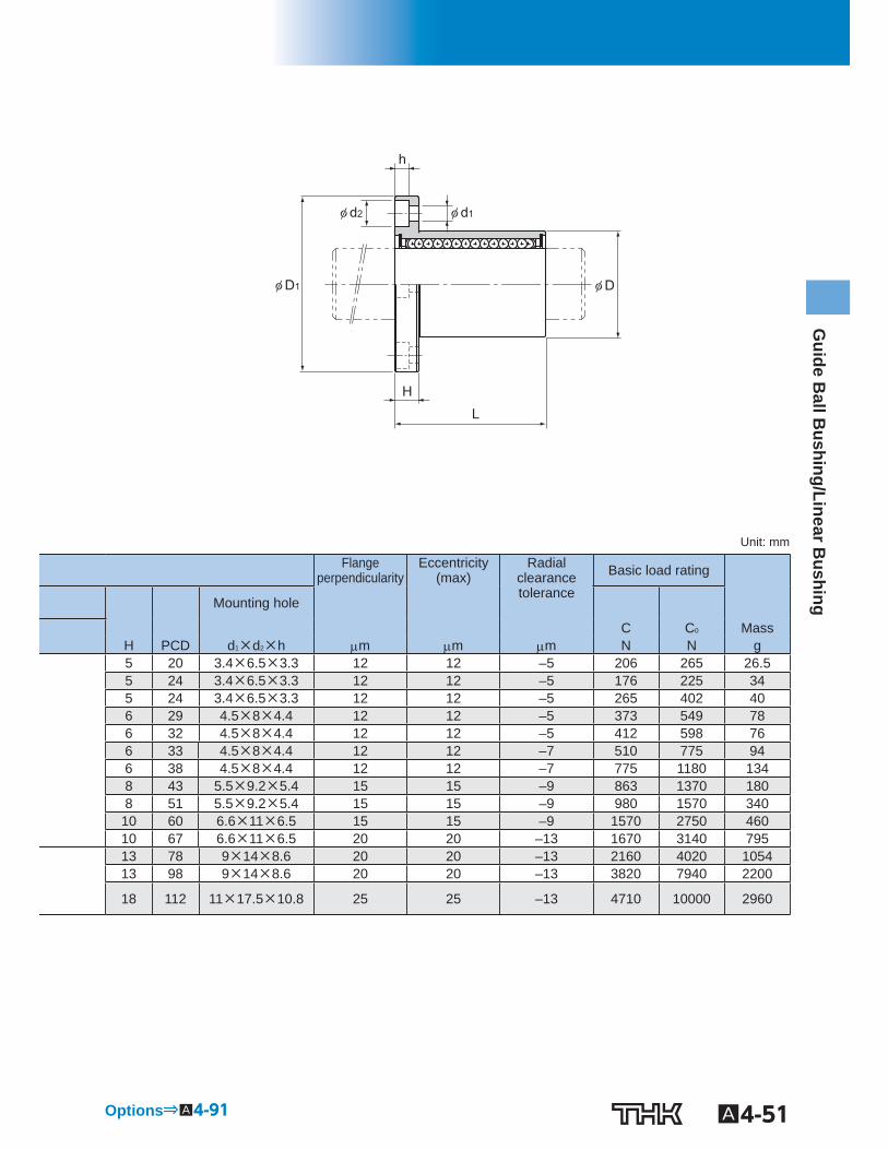
A4-51
Guide B
all Bushing/Linear B
ushing
φ D1
φ d2 φ d1
φ D
L H
h
Unit: mm
Flangeperpendicularity
Eccentricity(max)
Radial clearance tolerance
Basic load rating
Mounting hole
C C 0 Mass H PCD d 1 ×d 2 ×h m m m N N g 5 20 3.4×6.5×3.3 12 12 –5 206 265 26.5 5 24 3.4×6.5×3.3 12 12 –5 176 225 34 5 24 3.4×6.5×3.3 12 12 –5 265 402 40 6 29 4.5×8×4.4 12 12 –5 373 549 78 6 32 4.5×8×4.4 12 12 –5 412 598 76 6 33 4.5×8×4.4 12 12 –7 510 775 94 6 38 4.5×8×4.4 12 12 –7 775 1180 134 8 43 5.5×9.2×5.4 15 15 –9 863 1370 180 8 51 5.5×9.2×5.4 15 15 –9 980 1570 340
10 60 6.6×11×6.5 15 15 –9 1570 2750 460 10 67 6.6×11×6.5 20 20 –13 1670 3140 795 13 78 9×14×8.6 20 20 –13 2160 4020 1054 13 98 9×14×8.6 20 20 –13 3820 7940 2200
18 112 11×17.5×10.8 25 25 –13 4710 10000 2960
Options⇒A4-91
A4-52 To download a desired data, search for the corresponding model number in the Technical site. https://tech.thk.com
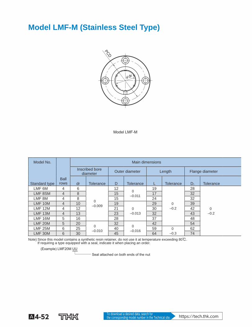
Model LMF-M (Stainless Steel Type)
Model LMF-M
φ dr
PCD
Model No. Main dimensions
Inscribed borediameter Outer diameter Length Flange diameter
Ball rows
Standard type dr Tolerance D Tolerance L Tolerance D 1 Tolerance
LMF 6M 4 6
0 –0.009
12 0
–0.011
19
0 –0.2
28
0 –0.2
LMF 8SM 4 8 15 17 32 LMF 8M 4 8 15 24 32 LMF 10M 4 10 19
0 –0.013
29 39 LMF 12M 4 12 21 30 42 LMF 13M 4 13 23 32 43 LMF 16M 5 16 28 37 48 LMF 20M 5 20
0 –0.010
32 0
–0.016
42 54 LMF 25M 6 25 40 59 0
–0.3 62
LMF 30M 6 30 45 64 74 Note) Since this model contains a synthetic resin retainer, do not use it at temperature exceeding 80℃.
If requiring a type equipped with a seal, indicate it when placing an order.
Seal attached on both ends of the nut (Example) LMF20M UU
A4-53
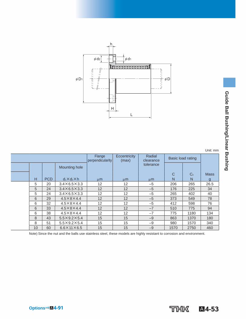
Guide B
all Bushing/Linear B
ushing
φ D1
φ d2 φ d1
φ D
L H
h
Unit: mm
Flangeperpendicularity
Eccentricity(max)
Radial clearance tolerance
Basic load rating
Mounting hole
C C 0 Mass H PCD d 1 ×d 2 ×h m m m N N g 5 20 3.4×6.5×3.3 12 12 –5 206 265 26.5 5 24 3.4×6.5×3.3 12 12 –5 176 225 34 5 24 3.4×6.5×3.3 12 12 –5 265 402 40 6 29 4.5×8×4.4 12 12 –5 373 549 78 6 32 4.5×8×4.4 12 12 –5 412 598 76 6 33 4.5×8×4.4 12 12 –7 510 775 94 6 38 4.5×8×4.4 12 12 –7 775 1180 134 8 43 5.5×9.2×5.4 15 15 –9 863 1370 180 8 51 5.5×9.2×5.4 15 15 –9 980 1570 340
10 60 6.6×11×6.5 15 15 –9 1570 2750 460 Note) Since the nut and the balls use stainless steel, these models are highly resistant to corrosion and environment.
Options⇒A4-91
A4-54 To download a desired data, search for the corresponding model number in the Technical site. https://tech.thk.com
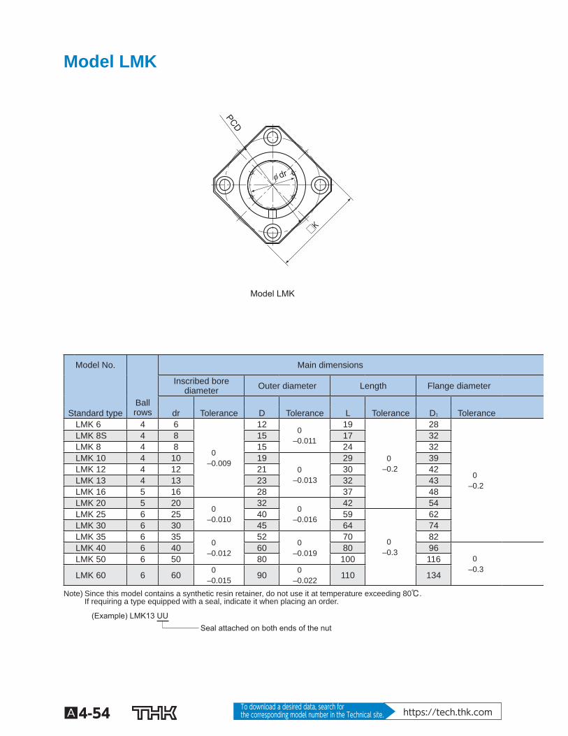
Model LMK
Model LMK
□K
φ dr
PCD
Model No. Main dimensions
Inscribed borediameter Outer diameter Length Flange diameter
Ball rows
Standard type dr Tolerance D Tolerance L Tolerance D 1 Tolerance
LMK 6 4 6
0 –0.009
12 0
–0.011
19
0 –0.2
28
0 –0.2
LMK 8S 4 8 15 17 32 LMK 8 4 8 15 24 32 LMK 10 4 10 19
0 –0.013
29 39 LMK 12 4 12 21 30 42 LMK 13 4 13 23 32 43 LMK 16 5 16 28 37 48 LMK 20 5 20
0 –0.010
32 0
–0.016
42 54 LMK 25 6 25 40 59
0 –0.3
62 LMK 30 6 30 45 64 74 LMK 35 6 35
0 –0.012
52 0
–0.019
70 82 LMK 40 6 40 60 80 96
0 –0.3
LMK 50 6 50 80 100 116
LMK 60 6 60 0 –0.015 90 0
–0.022 110 134
Note) Since this model contains a synthetic resin retainer, do not use it at temperature exceeding 80℃. If requiring a type equipped with a seal, indicate it when placing an order.
Seal attached on both ends of the nut (Example) LMK13 UU
A4-55
Guide B
all Bushing/Linear B
ushing
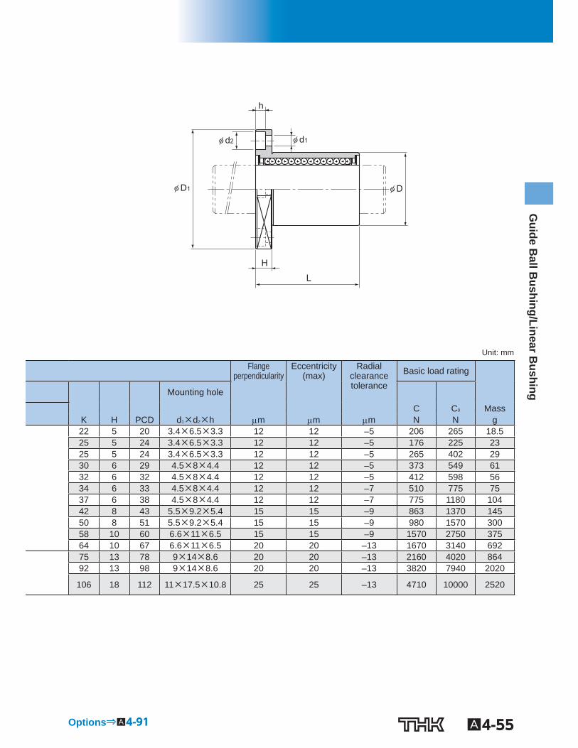
φ D1
φ d2 φ d1
φ D
L
H
h
Unit: mm
Flangeperpendicularity
Eccentricity(max)
Radial clearance tolerance
Basic load rating
Mounting hole
C C 0 Mass K H PCD d 1 ×d 2 ×h m m m N N g 22 5 20 3.4×6.5×3.3 12 12 –5 206 265 18.5 25 5 24 3.4×6.5×3.3 12 12 –5 176 225 23 25 5 24 3.4×6.5×3.3 12 12 –5 265 402 29 30 6 29 4.5×8×4.4 12 12 –5 373 549 61 32 6 32 4.5×8×4.4 12 12 –5 412 598 56 34 6 33 4.5×8×4.4 12 12 –7 510 775 75 37 6 38 4.5×8×4.4 12 12 –7 775 1180 104 42 8 43 5.5×9.2×5.4 15 15 –9 863 1370 145 50 8 51 5.5×9.2×5.4 15 15 –9 980 1570 300 58 10 60 6.6×11×6.5 15 15 –9 1570 2750 375 64 10 67 6.6×11×6.5 20 20 –13 1670 3140 692 75 13 78 9×14×8.6 20 20 –13 2160 4020 864 92 13 98 9×14×8.6 20 20 –13 3820 7940 2020
106 18 112 11×17.5×10.8 25 25 –13 4710 10000 2520
Options⇒A4-91
A4-56 To download a desired data, search for the corresponding model number in the Technical site. https://tech.thk.com
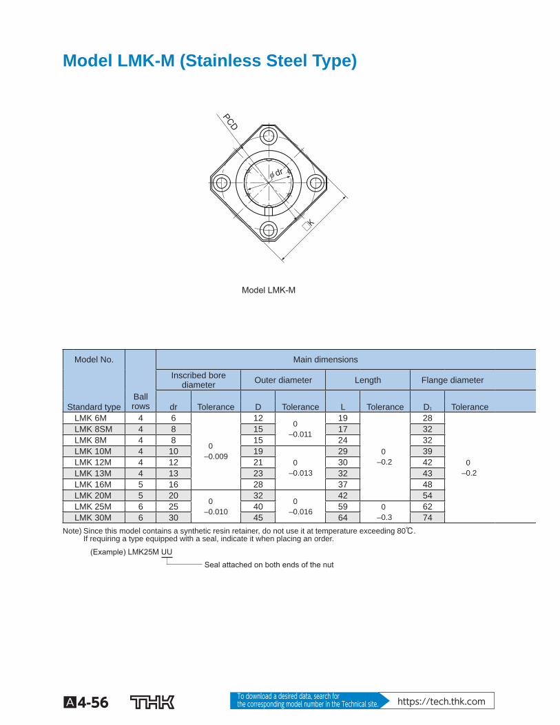
Model LMK-M (Stainless Steel Type)
Model LMK-M
□K
φ dr
PCD
Model No. Main dimensions
Inscribed borediameter Outer diameter Length Flange diameter
Ball rows
Standard type dr Tolerance D Tolerance L Tolerance D 1 Tolerance
LMK 6M 4 6
0 –0.009
12 0
–0.011
19
0 –0.2
28
0 –0.2
LMK 8SM 4 8 15 17 32 LMK 8M 4 8 15 24 32 LMK 10M 4 10 19
0 –0.013
29 39 LMK 12M 4 12 21 30 42 LMK 13M 4 13 23 32 43 LMK 16M 5 16 28 37 48 LMK 20M 5 20
0 –0.010
32 0
–0.016
42 54 LMK 25M 6 25 40 59 0
–0.3 62
LMK 30M 6 30 45 64 74 Note) Since this model contains a synthetic resin retainer, do not use it at temperature exceeding 80℃.
If requiring a type equipped with a seal, indicate it when placing an order.
Seal attached on both ends of the nut (Example) LMK25M UU
A4-57
Guide B
all Bushing/Linear B
ushing
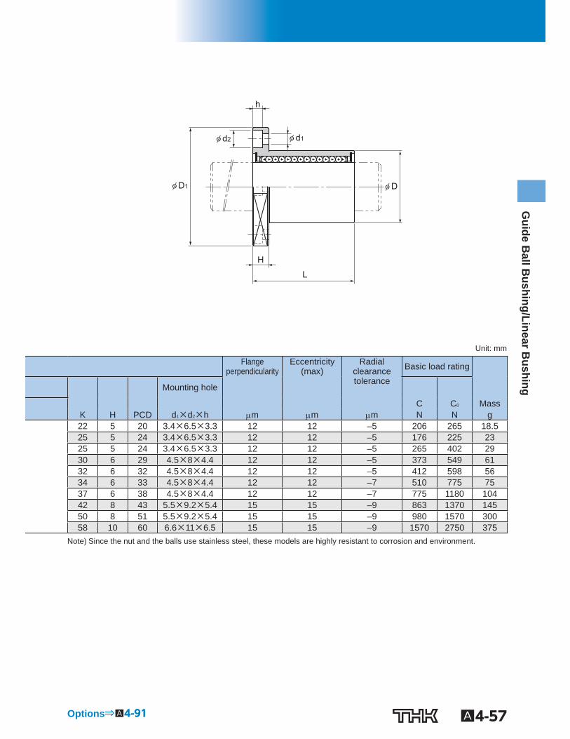
φ D1
φ d2 φ d1
φ D
L
H
h
Unit: mm
Flangeperpendicularity
Eccentricity(max)
Radial clearance tolerance
Basic load rating
Mounting hole
C C 0 Mass K H PCD d 1 ×d 2 ×h m m m N N g 22 5 20 3.4×6.5×3.3 12 12 –5 206 265 18.5 25 5 24 3.4×6.5×3.3 12 12 –5 176 225 23 25 5 24 3.4×6.5×3.3 12 12 –5 265 402 29 30 6 29 4.5×8×4.4 12 12 –5 373 549 61 32 6 32 4.5×8×4.4 12 12 –5 412 598 56 34 6 33 4.5×8×4.4 12 12 –7 510 775 75 37 6 38 4.5×8×4.4 12 12 –7 775 1180 104 42 8 43 5.5×9.2×5.4 15 15 –9 863 1370 145 50 8 51 5.5×9.2×5.4 15 15 –9 980 1570 300 58 10 60 6.6×11×6.5 15 15 –9 1570 2750 375
Note) Since the nut and the balls use stainless steel, these models are highly resistant to corrosion and environment.
Options⇒A4-91
A4-58 To download a desired data, search for the corresponding model number in the Technical site. https://tech.thk.com
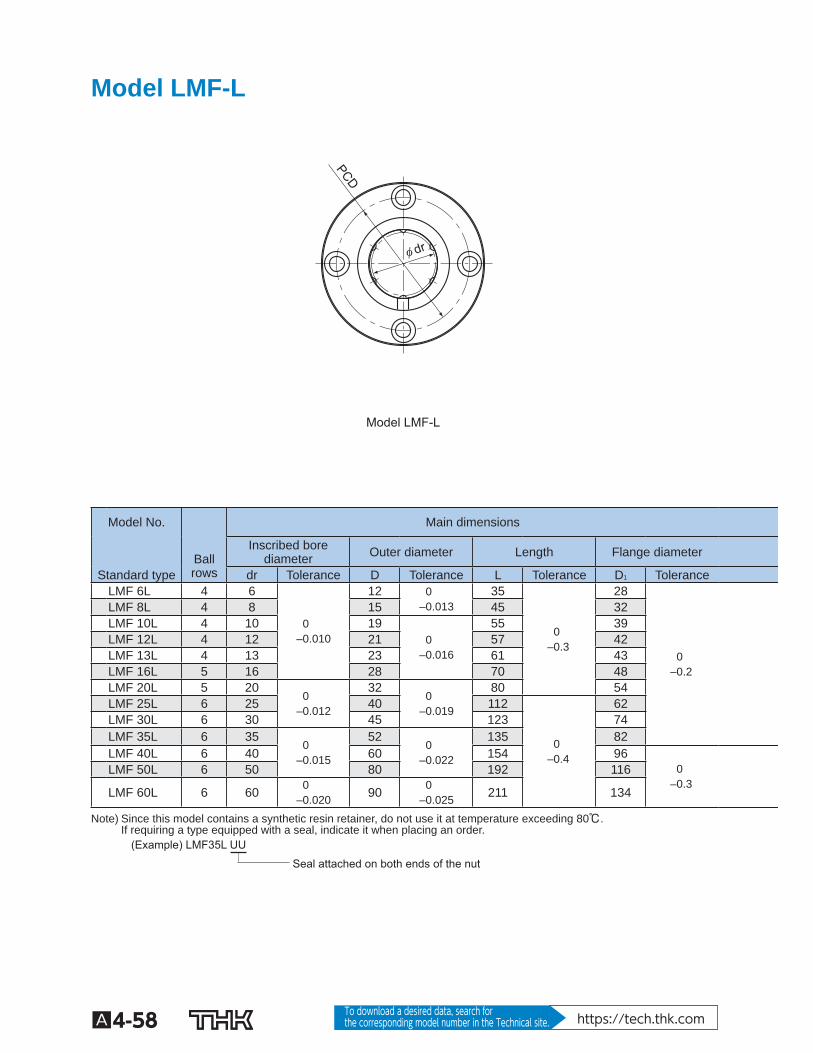
Model LMF-L
Model LMF-L
φ dr
PCD
Model No. Main dimensions
Ball rows
Inscribed borediameter Outer diameter Length Flange diameter
Standard type dr Tolerance D Tolerance L Tolerance D 1 Tolerance LMF 6L 4 6
0 –0.010
12 0 –0.013
35
0 –0.3
28
0 –0.2
LMF 8L 4 8 15 45 32 LMF 10L 4 10 19
0 –0.016
55 39 LMF 12L 4 12 21 57 42 LMF 13L 4 13 23 61 43 LMF 16L 5 16 28 70 48 LMF 20L 5 20
0 –0.012
32 0
–0.019
80 54 LMF 25L 6 25 40 112
0 –0.4
62 LMF 30L 6 30 45 123 74 LMF 35L 6 35
0 –0.015
52 0
–0.022
135 82 LMF 40L 6 40 60 154 96
0 –0.3
LMF 50L 6 50 80 192 116
LMF 60L 6 60 0 –0.020 90 0
–0.025 211 134
Note) Since this model contains a synthetic resin retainer, do not use it at temperature exceeding 80℃. If requiring a type equipped with a seal, indicate it when placing an order.
Seal attached on both ends of the nut
(Example) LMF35L UU
A4-59
Guide B
all Bushing/Linear B
ushing
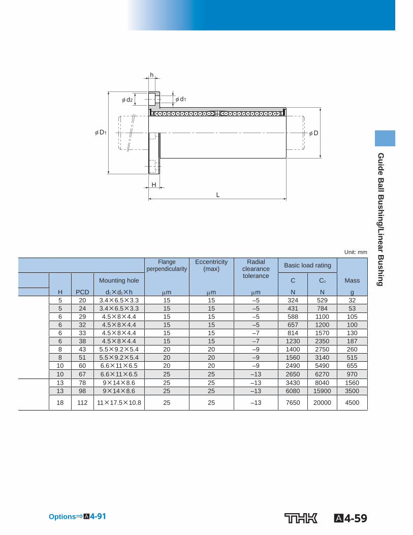
φ D1
φ d2 φ d1
φ D
L H
h
Unit: mm
Flangeperpendicularity
Eccentricity(max)
Radial clearance tolerance
Basic load rating
Mounting hole C C 0 Mass
H PCD d 1 ×d 2 ×h m m m N N g 5 20 3.4×6.5×3.3 15 15 –5 324 529 32 5 24 3.4×6.5×3.3 15 15 –5 431 784 53 6 29 4.5×8×4.4 15 15 –5 588 1100 105 6 32 4.5×8×4.4 15 15 –5 657 1200 100 6 33 4.5×8×4.4 15 15 –7 814 1570 130 6 38 4.5×8×4.4 15 15 –7 1230 2350 187 8 43 5.5×9.2×5.4 20 20 –9 1400 2750 260 8 51 5.5×9.2×5.4 20 20 –9 1560 3140 515
10 60 6.6×11×6.5 20 20 –9 2490 5490 655 10 67 6.6×11×6.5 25 25 –13 2650 6270 970 13 78 9×14×8.6 25 25 –13 3430 8040 1560 13 98 9×14×8.6 25 25 –13 6080 15900 3500
18 112 11×17.5×10.8 25 25 –13 7650 20000 4500
Options⇒A4-91

A4-60 To download a desired data, search for the corresponding model number in the Technical site. https://tech.thk.com
Model LMF-ML (Stainless Steel Type)
Model LMF-ML
φ dr
PCD
Model No. Main dimensions
Ball rows
Inscribed borediameter Outer diameter Length Flange diameter
Standard type dr Tolerance D Tolerance L Tolerance D 1 Tolerance LMF 6ML 4 6
0 –0.010
12 0 –0.013
35
0 –0.3
28
0 –0.2
LMF 8ML 4 8 15 45 32 LMF 10ML 4 10 19
0 –0.016
55 39 LMF 12ML 4 12 21 57 42 LMF 13ML 4 13 23 61 43 LMF 16ML 5 16 28 70 48 LMF 20ML 5 20
0 –0.012
32 0
–0.019
80 54 LMF 25ML 6 25 40 112 0
–0.4 62
LMF 30ML 6 30 45 123 74 Note) Since this model contains a synthetic resin retainer, do not use it at temperature exceeding 80℃.
If requiring a type equipped with a seal, indicate it when placing an order.
Seal attached on both ends of the nut
(Example) LMF13ML UU
A4-61
Guide B
all Bushing/Linear B
ushing
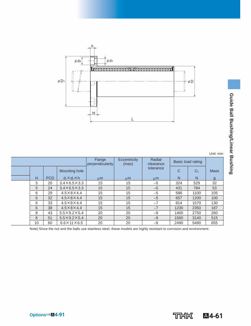
φ D1
φ d2 φ d1
φ D
L H
h
Unit: mm
Flangeperpendicularity
Eccentricity(max)
Radialclearance tolerance
Basic load rating
Mounting hole C C 0 Mass
H PCD d 1 ×d 2 ×h m m m N N g 5 20 3.4×6.5×3.3 15 15 –5 324 529 32 5 24 3.4×6.5×3.3 15 15 –5 431 784 53 6 29 4.5×8×4.4 15 15 –5 588 1100 105 6 32 4.5×8×4.4 15 15 –5 657 1200 100 6 33 4.5×8×4.4 15 15 –7 814 1570 130 6 38 4.5×8×4.4 15 15 –7 1230 2350 187 8 43 5.5×9.2×5.4 20 20 –9 1400 2750 260 8 51 5.5×9.2×5.4 20 20 –9 1560 3140 515
10 60 6.6×11×6.5 20 20 –9 2490 5490 655 Note) Since the nut and the balls use stainless steel, these models are highly resistant to corrosion and environment.
Options⇒A4-91
A4-62 To download a desired data, search for the corresponding model number in the Technical site. https://tech.thk.com
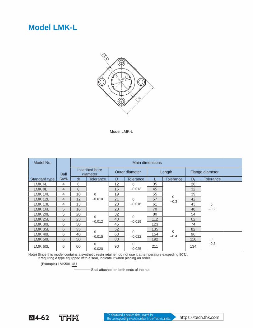
Model LMK-L
Model LMK-L
□K
φ dr
PCD
Model No. Main dimensions
Ball rows
Inscribed borediameter Outer diameter Length Flange diameter
Standard type dr Tolerance D Tolerance L Tolerance D 1 Tolerance LMK 6L 4 6
0 –0.010
12 0 –0.013
35
0 –0.3
28
0 –0.2
LMK 8L 4 8 15 45 32 LMK 10L 4 10 19
0 –0.016
55 39 LMK 12L 4 12 21 57 42 LMK 13L 4 13 23 61 43 LMK 16L 5 16 28 70 48 LMK 20L 5 20
0 –0.012
32 0
–0.019
80 54 LMK 25L 6 25 40 112
0 –0.4
62 LMK 30L 6 30 45 123 74 LMK 35L 6 35
0 –0.015
52 0
–0.022
135 82 LMK 40L 6 40 60 154 96
0 –0.3
LMK 50L 6 50 80 192 116
LMK 60L 6 60 0 –0.020 90 0
–0.025 211 134
Note) Since this model contains a synthetic resin retainer, do not use it at temperature exceeding 80℃. If requiring a type equipped with a seal, indicate it when placing an order.
Seal attached on both ends of the nut (Example) LMK50L UU
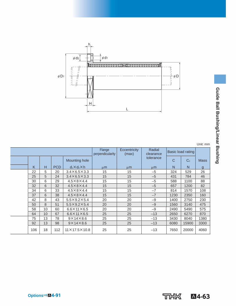
A4-63
Guide B
all Bushing/Linear B
ushing
φ D1
φ d2 φ d1
φ D
L H
h
Unit: mm
Flangeperpendicularity
Eccentricity(max)
Radial clearance tolerance
Basic load rating
Mounting hole C C 0 Mass
K H PCD d 1 ×d 2 ×h m m m N N g 22 5 20 3.4×6.5×3.3 15 15 –5 324 529 26 25 5 24 3.4×6.5×3.3 15 15 –5 431 784 46 30 6 29 4.5×8×4.4 15 15 –5 588 1100 88 32 6 32 4.5×8×4.4 15 15 –5 657 1200 82 34 6 33 4.5×8×4.4 15 15 –7 814 1570 108 37 6 38 4.5×8×4.4 15 15 –7 1230 2350 160 42 8 43 5.5×9.2×5.4 20 20 –9 1400 2750 230 50 8 51 5.5×9.2×5.4 20 20 –9 1560 3140 475 58 10 60 6.6×11×6.5 20 20 –9 2490 5490 575 64 10 67 6.6×11×6.5 25 25 –13 2650 6270 870 75 13 78 9×14×8.6 25 25 –13 3430 8040 1380 92 13 98 9×14×8.6 25 25 –13 6080 15900 3300
106 18 112 11×17.5×10.8 25 25 –13 7650 20000 4060
Options⇒A4-91
A4-64 To download a desired data, search for the corresponding model number in the Technical site. https://tech.thk.com
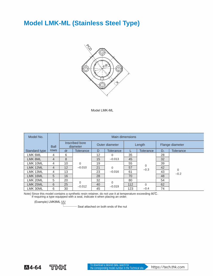
Model LMK-ML (Stainless Steel Type)
Model LMK-ML
□K
φ dr
PCD
Model No. Main dimensions
Ball rows
Inscribed borediameter Outer diameter Length Flange diameter
Standard type dr Tolerance D Tolerance L Tolerance D 1 Tolerance LMK 6ML 4 6
0 –0.010
12 0 –0.013
35
0 –0.3
28
0 –0.2
LMK 8ML 4 8 15 45 32 LMK 10ML 4 10 19
0 –0.016
55 39 LMK 12ML 4 12 21 57 42 LMK 13ML 4 13 23 61 43 LMK 16ML 5 16 28 70 48 LMK 20ML 5 20
0 –0.012
32 0
–0.019
80 54 LMK 25ML 6 25 40 112 0
–0.4 62
LMK 30ML 6 30 45 123 74 Note) Since this model contains a synthetic resin retainer, do not use it at temperature exceeding 80℃.
If requiring a type equipped with a seal, indicate it when placing an order.
Seal attached on both ends of the nut (Example) LMK8ML UU
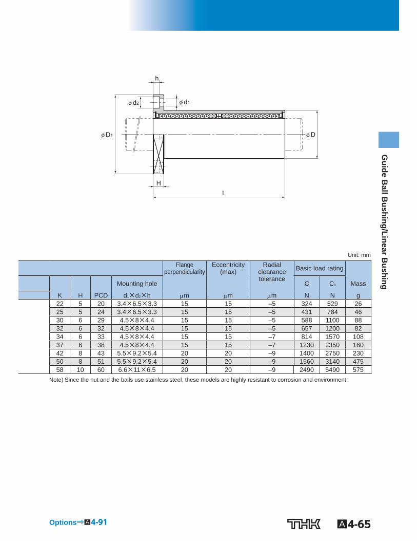
A4-65
Guide B
all Bushing/Linear B
ushing
φ D1
φ d2 φ d1
φ D
L H
h
Unit: mm
Flangeperpendicularity
Eccentricity(max)
Radialclearance tolerance
Basic load rating
Mounting hole C C 0 Mass
K H PCD d 1 ×d 2 ×h m m m N N g 22 5 20 3.4×6.5×3.3 15 15 –5 324 529 26 25 5 24 3.4×6.5×3.3 15 15 –5 431 784 46 30 6 29 4.5×8×4.4 15 15 –5 588 1100 88 32 6 32 4.5×8×4.4 15 15 –5 657 1200 82 34 6 33 4.5×8×4.4 15 15 –7 814 1570 108 37 6 38 4.5×8×4.4 15 15 –7 1230 2350 160 42 8 43 5.5×9.2×5.4 20 20 –9 1400 2750 230 50 8 51 5.5×9.2×5.4 20 20 –9 1560 3140 475 58 10 60 6.6×11×6.5 20 20 –9 2490 5490 575
Note) Since the nut and the balls use stainless steel, these models are highly resistant to corrosion and environment.
Options⇒A4-91
A4-66 To download a desired data, search for the corresponding model number in the Technical site. https://tech.thk.com
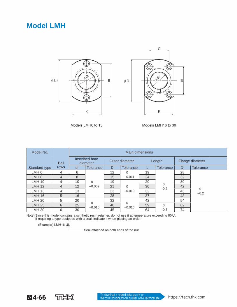
Model LMH
Models LMH6 to 13 Models LMH16 to 30
φ drφ dr
φ D1φ D1 B B
K K
C
Model No. Main dimensions
Ball rows
Inscribed borediameter Outer diameter Length Flange diameter
Standard type dr Tolerance D Tolerance L Tolerance D 1 Tolerance LMH 6 4 6
0 –0.009
12 0 –0.011
19
0 –0.2
28
0 –0.2
LMH 8 4 8 15 24 32 LMH 10 4 10 19
0 –0.013
29 39 LMH 12 4 12 21 30 42 LMH 13 4 13 23 32 43 LMH 16 5 16 28 37 48 LMH 20 5 20
0 –0.010
32 0
–0.016
42 54 LMH 25 6 25 40 59 0
–0.3 62
LMH 30 6 30 45 64 74 Note) Since this model contains a synthetic resin retainer, do not use it at temperature exceeding 80℃.
If requiring a type equipped with a seal, indicate it when placing an order.
Seal attached on both ends of the nut (Example) LMH16 UU
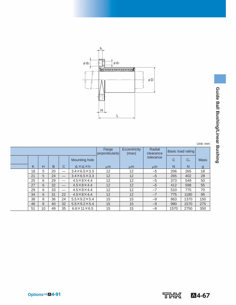
A4-67
Guide B
all Bushing/Linear B
ushing
φ d2 φ d1
φ D
L H
h
Unit: mm
Flange perpendicularity
Eccentricity(max)
Radialclearance tolerance
Basic load rating
Mounting hole C C 0 Mass
K H B C d 1 ×d 2 ×h m m m N N g 18 5 20 — 3.4×6.5×3.3 12 12 –5 206 265 18 21 5 24 — 3.4×6.5×3.3 12 12 –5 265 402 28 25 6 29 — 4.5×8×4.4 12 12 –5 373 549 50 27 6 32 — 4.5×8×4.4 12 12 –5 412 598 55 29 6 33 — 4.5×8×4.4 12 12 –7 510 775 70 34 6 31 22 4.5×8×4.4 12 12 –7 775 1180 95 38 8 36 24 5.5×9.2×5.4 15 15 –9 863 1370 150 46 8 40 32 5.5×9.2×5.4 15 15 –9 980 1570 275 51 10 49 35 6.6×11×6.5 15 15 –9 1570 2750 350
Options⇒A4-91
A4-68 To download a desired data, search for the corresponding model number in the Technical site. https://tech.thk.com
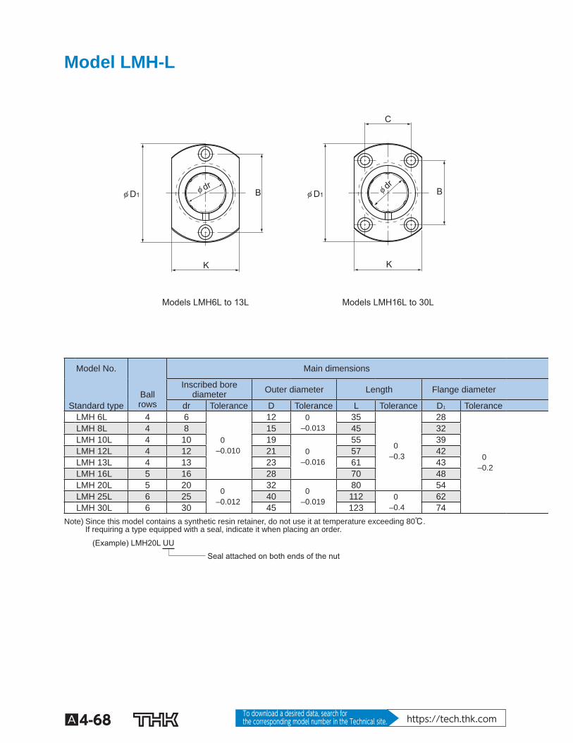
Model LMH-L
Models LMH6L to 13L Models LMH16L to 30L
φ dr φ drφ D1φ D1 B B
K K
C
Model No. Main dimensions
Ball rows
Inscribed borediameter Outer diameter Length Flange diameter
Standard type dr Tolerance D Tolerance L Tolerance D 1 Tolerance LMH 6L 4 6
0 –0.010
12 0 –0.013
35
0 –0.3
28
0 –0.2
LMH 8L 4 8 15 45 32 LMH 10L 4 10 19
0 –0.016
55 39 LMH 12L 4 12 21 57 42 LMH 13L 4 13 23 61 43 LMH 16L 5 16 28 70 48 LMH 20L 5 20
0 –0.012
32 0
–0.019
80 54 LMH 25L 6 25 40 112 0
–0.4 62
LMH 30L 6 30 45 123 74 Note) Since this model contains a synthetic resin retainer, do not use it at temperature exceeding 80℃.
If requiring a type equipped with a seal, indicate it when placing an order.
Seal attached on both ends of the nut (Example) LMH20L UU
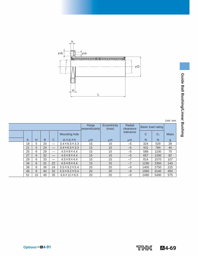
A4-69
Guide B
all Bushing/Linear B
ushing
φ d2 φ d1
φ D
L H
h
Unit: mm
Flange perpendicularity
Eccentricity(max)
Radialclearance tolerance
Basic load rating
Mounting hole C C 0 Mass
K H B C d 1 ×d 2 ×h m m m N N g 18 5 20 — 3.4×6.5×3.3 15 15 –5 324 529 28 21 5 24 — 3.4×6.5×3.3 15 15 –5 431 784 40 25 6 29 — 4.5×8×4.4 15 15 –5 588 1100 75 27 6 32 — 4.5×8×4.4 15 15 –5 657 1200 82 29 6 33 — 4.5×8×4.4 15 15 –7 814 1570 107 34 6 31 22 4.5×8×4.4 15 15 –7 1230 2350 143 38 8 36 24 5.5×9.2×5.4 20 20 –9 1400 2750 225 46 8 40 32 5.5×9.2×5.4 20 20 –9 1560 3140 450 51 10 49 35 6.6×11×6.5 20 20 –9 2490 5490 575
Options⇒A4-91
A4-70 To download a desired data, search for the corresponding model number in the Technical site. https://tech.thk.com
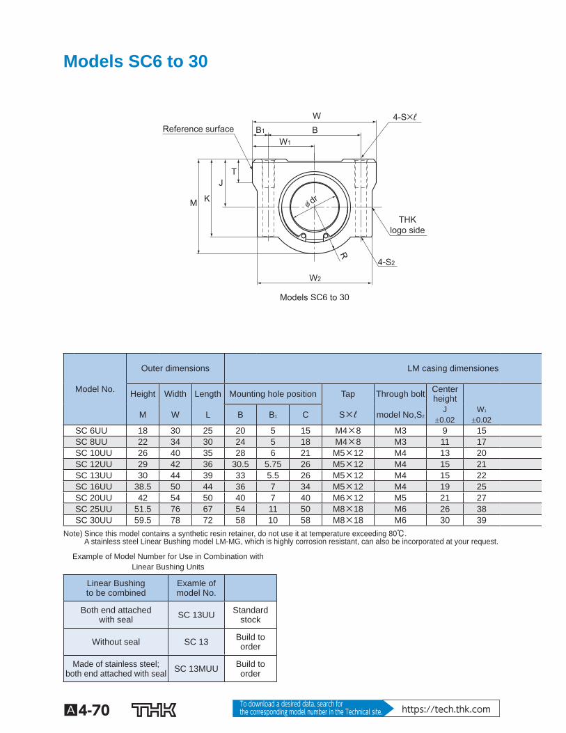
Models SC6 to 30
Models SC6 to 30
Reference surface
THK logo side
W B B1
K
W2
R
W1
T J
M φ dr
4-S2
4-S×ℓ
Model No.
Outer dimensions LM casing dimensiones
Height Width Length Mounting hole position Tap Through bolt Centerheight
M W L B B 1 C S×ℓ model No,S 2 J 0.02
W 1 0.02
SC 6UU 18 30 25 20 5 15 M4×8 M3 9 15 SC 8UU 22 34 30 24 5 18 M4×8 M3 11 17 SC 10UU 26 40 35 28 6 21 M5×12 M4 13 20 SC 12UU 29 42 36 30.5 5.75 26 M5×12 M4 15 21 SC 13UU 30 44 39 33 5.5 26 M5×12 M4 15 22 SC 16UU 38.5 50 44 36 7 34 M5×12 M4 19 25 SC 20UU 42 54 50 40 7 40 M6×12 M5 21 27 SC 25UU 51.5 76 67 54 11 50 M8×18 M6 26 38 SC 30UU 59.5 78 72 58 10 58 M8×18 M6 30 39 Note) Since this model contains a synthetic resin retainer, do not use it at temperature exceeding 80℃.
A stainless steel Linear Bushing model LM-MG, which is highly corrosion resistant, can also be incorporated at your request.
Example of Model Number for Use in Combination with Linear Bushing Units
Linear Bushingto be combined
Examle ofmodel No.
Both end attachedwith seal SC 13UU Standard
stock
Without seal SC 13 Build to order
Made of stainless steel;both end attached with seal SC 13MUU Build to
order
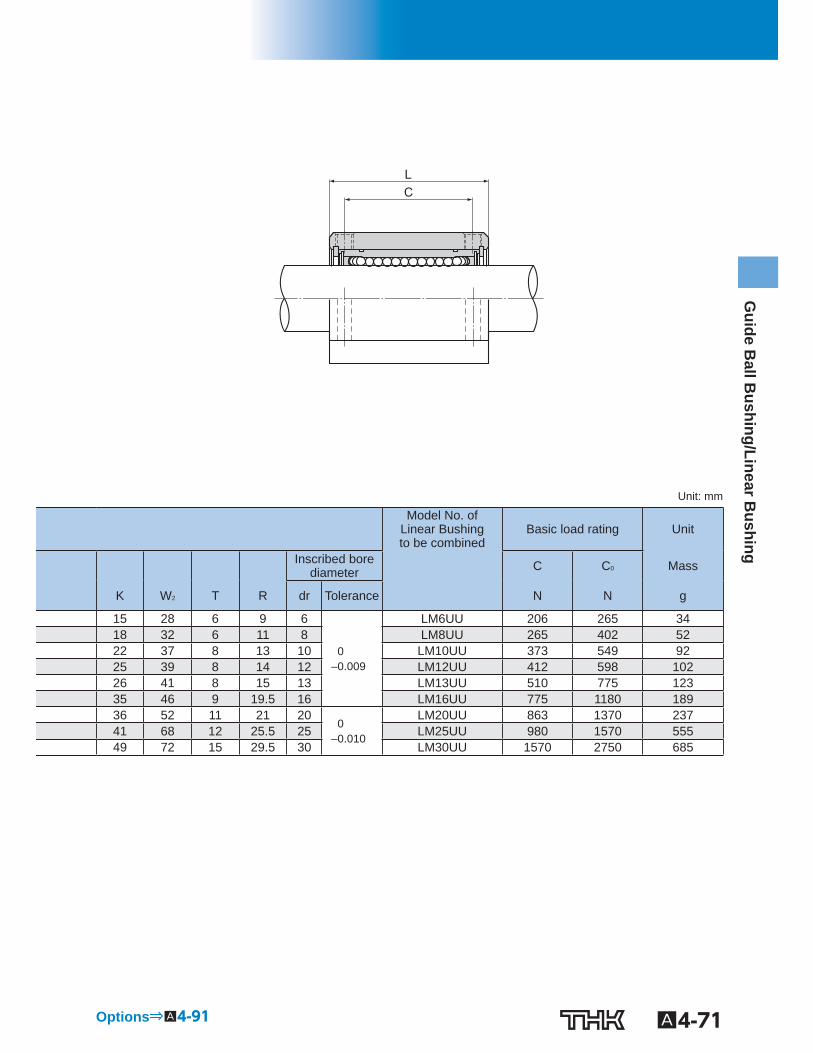
A4-71
Guide B
all Bushing/Linear B
ushing
C L
Unit: mm
Model No. of Linear Bushing to be combined
Basic load rating Unit
Inscribed borediameter C C 0 Mass
K W 2 T R dr Tolerance N N g
15 28 6 9 6
0 –0.009
LM6UU 206 265 34 18 32 6 11 8 LM8UU 265 402 52 22 37 8 13 10 LM10UU 373 549 92 25 39 8 14 12 LM12UU 412 598 102 26 41 8 15 13 LM13UU 510 775 123 35 46 9 19.5 16 LM16UU 775 1180 189 36 52 11 21 20
0 –0.010
LM20UU 863 1370 237 41 68 12 25.5 25 LM25UU 980 1570 555 49 72 15 29.5 30 LM30UU 1570 2750 685
Options⇒A4-91
A4-72 To download a desired data, search for the corresponding model number in the Technical site. https://tech.thk.com
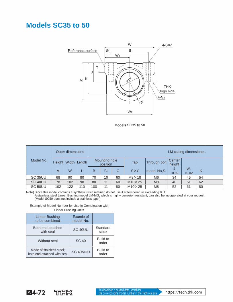
Models SC35 to 50
Models SC35 to 50
Reference surface
THK logo side
W B B1
K
W2
R
W1
T J
M
4-S2
4-S×ℓ
φ dr
Model No.
Outer dimensions LM casing dimensiones
Height Width Length Mounting holeposition Tap Through bolt Center
height
M W L B B 1 C S×ℓ model No,S 2 J 0.02
W 1 0.02 K
SC 35UU 68 90 80 70 10 60 M8×18 M6 34 45 54 SC 40UU 78 102 90 80 11 60 M10×25 M8 40 51 62 SC 50UU 102 122 110 100 11 80 M10×25 M8 52 61 80 Note) Since this model contains a synthetic resin retainer, do not use it at temperature exceeding 80℃.
A stainless steel Linear Bushing model LM-MG, which is highly corrosion resistant, can also be incorporated at your request. (Model SC50 does not include a stainless type.)
Example of Model Number for Use in Combination with Linear Bushing Units
Linear Bushingto be combined
Examle ofmodel No.
Both end attachedwith seal SC 40UU Standard
stock
Without seal SC 40 Build to order
Made of stainless steel;both end attached with seal SC 40MUU Build to
order
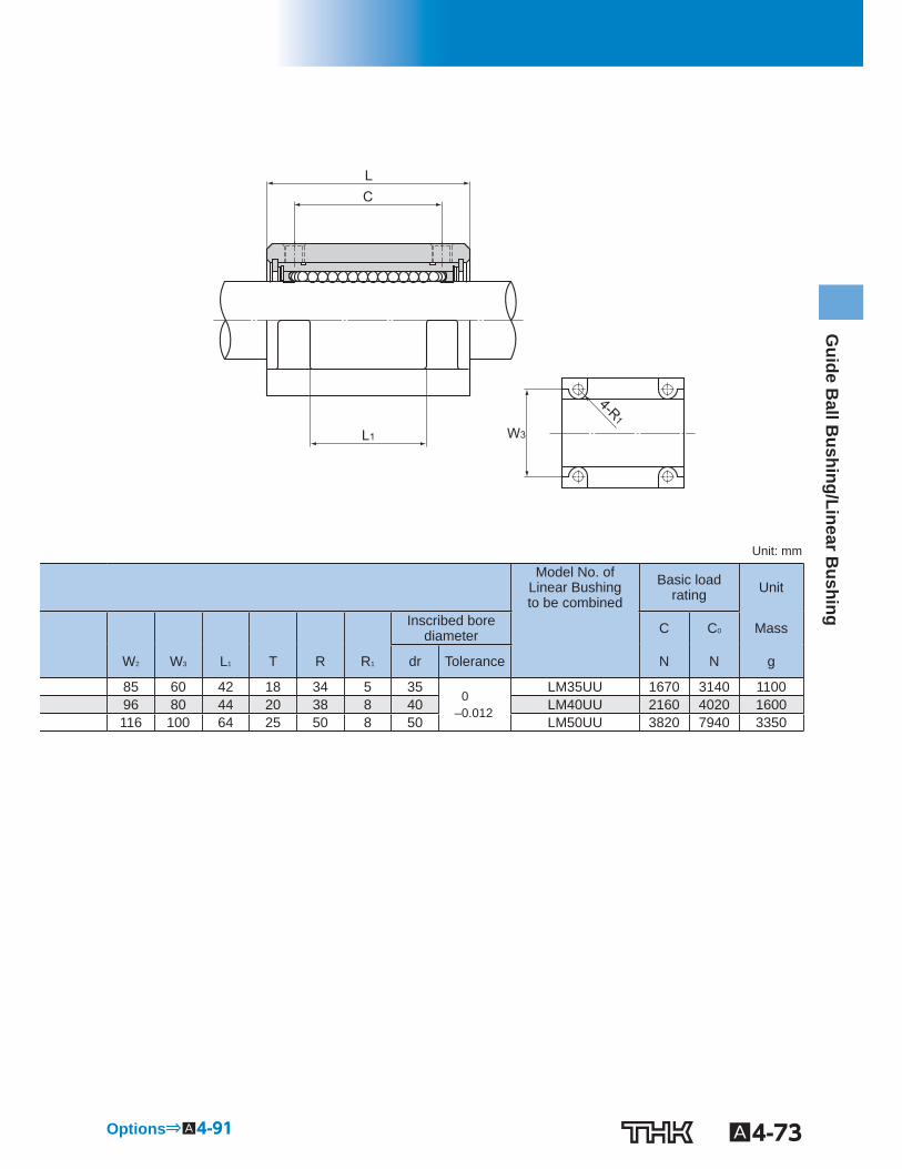
A4-73
Guide B
all Bushing/Linear B
ushing
C
4-R1
L
L1 W3
Unit: mm
Model No. of Linear Bushing to be combined
Basic loadrating Unit
Inscribed borediameter C C 0 Mass
W 2 W 3 L 1 T R R 1 dr Tolerance N N g
85 60 42 18 34 5 35 0
–0.012
LM35UU 1670 3140 1100 96 80 44 20 38 8 40 LM40UU 2160 4020 1600 116 100 64 25 50 8 50 LM50UU 3820 7940 3350
Options⇒A4-91
A4-74 To download a desired data, search for the corresponding model number in the Technical site. https://tech.thk.com
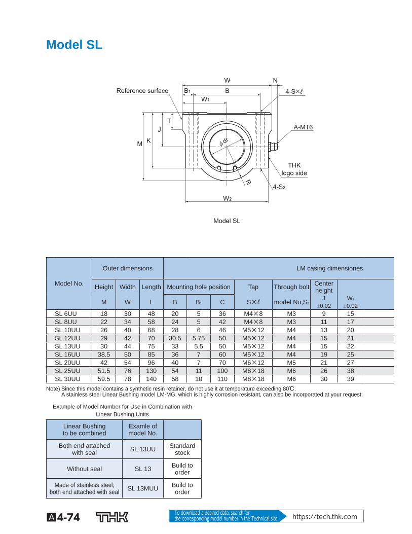
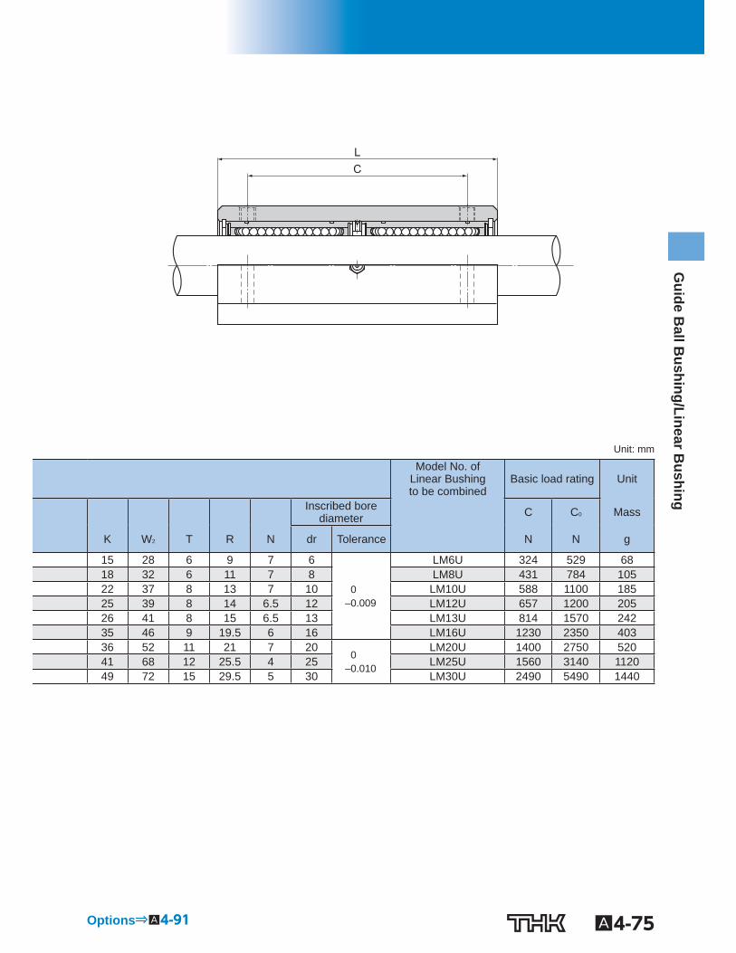
Model SL
Reference surface
THK logo side
Model SL
W N B B1
K
W2
R
W1
T J
M φ dr
4-S2
4-S×ℓ
A-MT6
Model No.
Outer dimensions LM casing dimensiones
Height Width Length Mounting hole position Tap Through bolt Centerheight
M W L B B 1 C S×ℓ model No,S 2 J 0.02
W 1 0.02
SL 6UU 18 30 48 20 5 36 M4×8 M3 9 15 SL 8UU 22 34 58 24 5 42 M4×8 M3 11 17 SL 10UU 26 40 68 28 6 46 M5×12 M4 13 20 SL 12UU 29 42 70 30.5 5.75 50 M5×12 M4 15 21 SL 13UU 30 44 75 33 5.5 50 M5×12 M4 15 22 SL 16UU 38.5 50 85 36 7 60 M5×12 M4 19 25 SL 20UU 42 54 96 40 7 70 M6×12 M5 21 27 SL 25UU 51.5 76 130 54 11 100 M8×18 M6 26 38 SL 30UU 59.5 78 140 58 10 110 M8×18 M6 30 39 Note) Since this model contains a synthetic resin retainer, do not use it at temperature exceeding 80℃.
A stainless steel Linear Bushing model LM-MG, which is highly corrosion resistant, can also be incorporated at your request.
Example of Model Number for Use in Combination with Linear Bushing Units
Linear Bushingto be combined
Examle ofmodel No.
Both end attachedwith seal SL 13UU Standard
stock
Without seal SL 13 Build to order
Made of stainless steel;both end attached with seal SL 13MUU Build to
order
A4-75
Guide B
all Bushing/Linear B
ushing
C L
Unit: mm
Model No. of Linear Bushingto be combined
Basic load rating Unit
Inscribed borediameter C C 0 Mass
K W 2 T R N dr Tolerance N N g
15 28 6 9 7 6
0 –0.009
LM6U 324 529 68 18 32 6 11 7 8 LM8U 431 784 105 22 37 8 13 7 10 LM10U 588 1100 185 25 39 8 14 6.5 12 LM12U 657 1200 205 26 41 8 15 6.5 13 LM13U 814 1570 242 35 46 9 19.5 6 16 LM16U 1230 2350 403 36 52 11 21 7 20
0 –0.010
LM20U 1400 2750 520 41 68 12 25.5 4 25 LM25U 1560 3140 1120 49 72 15 29.5 5 30 LM30U 2490 5490 1440
Options⇒A4-91
A4-76 To download a desired data, search for the corresponding model number in the Technical site. https://tech.thk.com
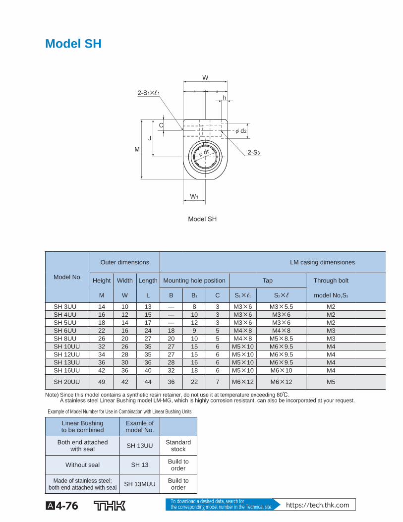
Model SH
Model SH
W
h
φ d2
W1
M
J
C
2-S1×ℓ1
2-S3φ dr
Model No.
Outer dimensions LM casing dimensiones
Height Width Length Mounting hole position Tap Through bolt
M W L B B 1 C S 1 ×ℓ 1 S 2 ×ℓ model No,S 3
SH 3UU 14 10 13 — 8 3 M3×6 M3×5.5 M2 SH 4UU 16 12 15 — 10 3 M3×6 M3×6 M2 SH 5UU 18 14 17 — 12 3 M3×6 M3×6 M2 SH 6UU 22 16 24 18 9 5 M4×8 M4×8 M3 SH 8UU 26 20 27 20 10 5 M4×8 M5×8.5 M3 SH 10UU 32 26 35 27 15 6 M5×10 M6×9.5 M4 SH 12UU 34 28 35 27 15 6 M5×10 M6×9.5 M4 SH 13UU 36 30 36 28 16 6 M5×10 M6×9.5 M4 SH 16UU 42 36 40 32 18 6 M5×10 M6×10 M4
SH 20UU 49 42 44 36 22 7 M6×12 M6×12 M5
Note) Since this model contains a synthetic resin retainer, do not use it at temperature exceeding 80℃. A stainless steel Linear Bushing model LM-MG, which is highly corrosion resistant, can also be incorporated at your request.
Example of Model Number for Use in Combination with Linear Bushing Units
Linear Bushingto be combined
Examle ofmodel No.
Both end attachedwith seal SH 13UU Standard
stock
Without seal SH 13 Build to order
Made of stainless steel;both end attached with seal SH 13MUU Build to
order
A4-77
Guide B
all Bushing/Linear B
ushing
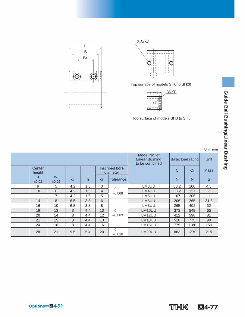
Top surface of models SH3 to SH5
Top surface of models SH6 to SH20
B1
B L
2-S2×ℓ
S2×ℓ
Unit: mm
Model No. of Linear Bushingto be combined
Basic load rating Unit
Centerheight Inscribed bore
diameter C C 0 Mass
J 0.02
W 1 0.02 d 2 h dr Tolerance N N g
9 5 4.2 1.5 3 0
–0.008
LM3UU 88.2 108 4.5 10 6 4.2 1.5 4 LM4UU 88.2 127 7 11 7 4.2 1.5 5 LM5UU 167 206 11 14 8 6.5 3.3 6
0 –0.009
LM6UU 206 265 21.6 16 10 6.5 3.3 8 LM8UU 265 402 32 19 13 8 4.4 10 LM10UU 373 549 65 20 14 8 4.4 12 LM12UU 412 598 81 21 15 8 4.4 13 LM13UU 510 775 90 24 18 8 4.4 16 LM16UU 775 1180 150
28 21 9.5 5.4 20 0 –0.010 LM20UU 863 1370 215
Options⇒A4-91
A4-78 To download a desired data, search for the corresponding model number in the Technical site. https://tech.thk.com
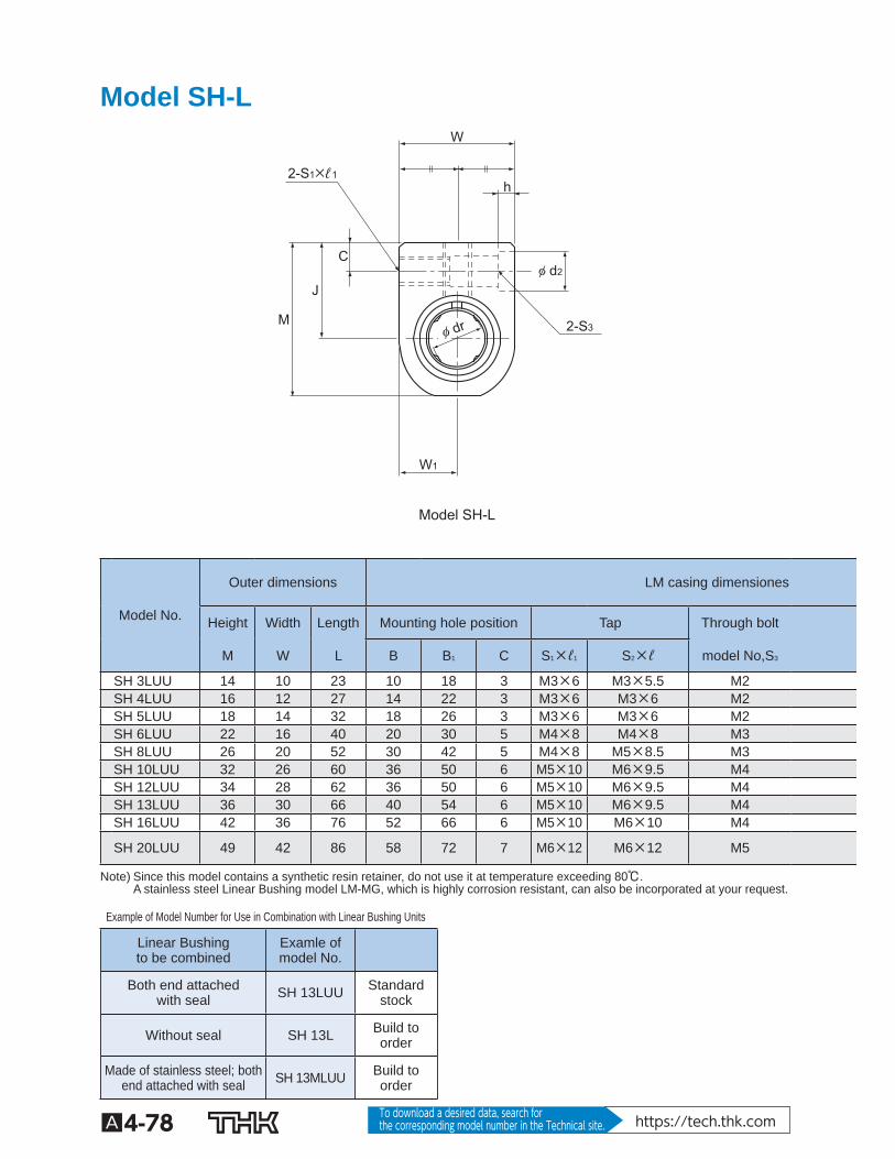
Model SH-L
Model SH-L
W
h
φ d2
W1
M
J
C
2-S1×ℓ1
2-S3 φ dr
Model No.
Outer dimensions LM casing dimensiones
Height Width Length Mounting hole position Tap Through bolt
M W L B B 1 C S 1 ×ℓ 1 S 2 ×ℓ model No,S 3
SH 3LUU 14 10 23 10 18 3 M3×6 M3×5.5 M2 SH 4LUU 16 12 27 14 22 3 M3×6 M3×6 M2 SH 5LUU 18 14 32 18 26 3 M3×6 M3×6 M2 SH 6LUU 22 16 40 20 30 5 M4×8 M4×8 M3 SH 8LUU 26 20 52 30 42 5 M4×8 M5×8.5 M3 SH 10LUU 32 26 60 36 50 6 M5×10 M6×9.5 M4 SH 12LUU 34 28 62 36 50 6 M5×10 M6×9.5 M4 SH 13LUU 36 30 66 40 54 6 M5×10 M6×9.5 M4 SH 16LUU 42 36 76 52 66 6 M5×10 M6×10 M4
SH 20LUU 49 42 86 58 72 7 M6×12 M6×12 M5
Note) Since this model contains a synthetic resin retainer, do not use it at temperature exceeding 80℃. A stainless steel Linear Bushing model LM-MG, which is highly corrosion resistant, can also be incorporated at your request.
Example of Model Number for Use in Combination with Linear Bushing Units
Linear Bushingto be combined
Examle ofmodel No.
Both end attachedwith seal SH 13LUU Standard
stock
Without seal SH 13L Build to order
Made of stainless steel; both end attached with seal SH 13MLUU Build to
order
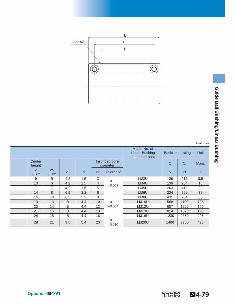
A4-79
Guide B
all Bushing/Linear B
ushing
B1
B
L
2-S2×ℓ
Unit: mm
Model No. of Linear Bushingto be combined
Basic load rating Unit
Centerheight Inscribed bore
diameter C C 0 Mass
J 0.02
W 1 0.02 d 2 h dr Tolerance N N g
9 5 4.2 1.5 3 0
–0.008
LM3U 139 216 8.5 10 6 4.2 1.5 4 LM4U 139 254 13 11 7 4.2 1.5 5 LM5U 263 412 22 14 8 6.5 3.3 6
0 –0.009
LM6U 324 529 35 16 10 6.5 3.3 8 LM8U 431 784 65 19 13 8 4.4 10 LM10U 588 1100 125 20 14 8 4.4 12 LM12U 657 1200 155 21 15 8 4.4 13 LM13U 814 1570 190 24 18 8 4.4 16 LM16U 1230 2350 295
28 21 9.5 5.4 20 0 –0.010 LM20U 1400 2750 425
Options⇒A4-91
A4-80 To download a desired data, search for the corresponding model number in the Technical site. https://tech.thk.com
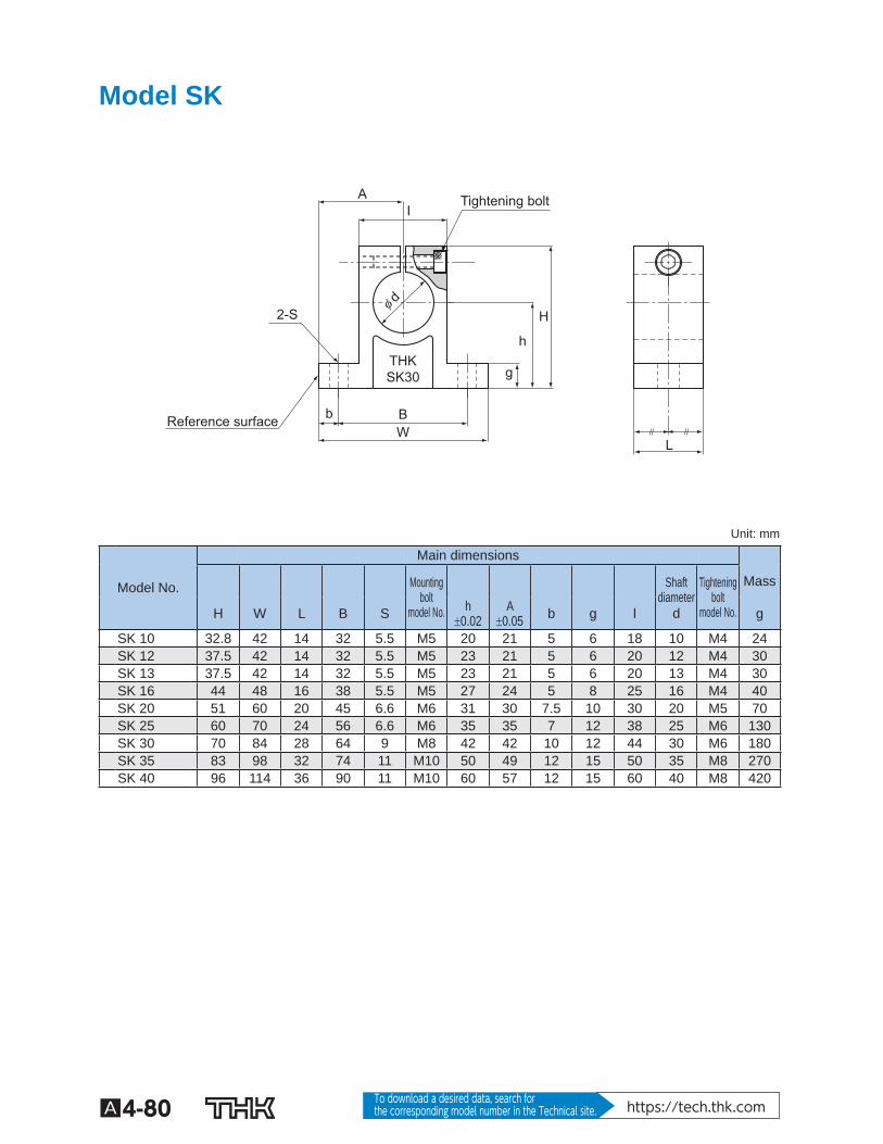
Model SK
Tightening bolt
Reference surface
I A
H
h
φ d
g THK SK30
B W
b
L
2-S
Unit: mm
Model No.
Main dimensions
Mounting bolt
model No.
Shaftdiameter
d
Tightening bolt
model No.
Mass
H W L B S h 0.02
A 0.05 b g l g
SK 10 32.8 42 14 32 5.5 M5 20 21 5 6 18 10 M4 24 SK 12 37.5 42 14 32 5.5 M5 23 21 5 6 20 12 M4 30 SK 13 37.5 42 14 32 5.5 M5 23 21 5 6 20 13 M4 30 SK 16 44 48 16 38 5.5 M5 27 24 5 8 25 16 M4 40 SK 20 51 60 20 45 6.6 M6 31 30 7.5 10 30 20 M5 70 SK 25 60 70 24 56 6.6 M6 35 35 7 12 38 25 M6 130 SK 30 70 84 28 64 9 M8 42 42 10 12 44 30 M6 180 SK 35 83 98 32 74 11 M10 50 49 12 15 50 35 M8 270 SK 40 96 114 36 90 11 M10 60 57 12 15 60 40 M8 420
A4-81
Guide B
all Bushing/Linear B
ushing
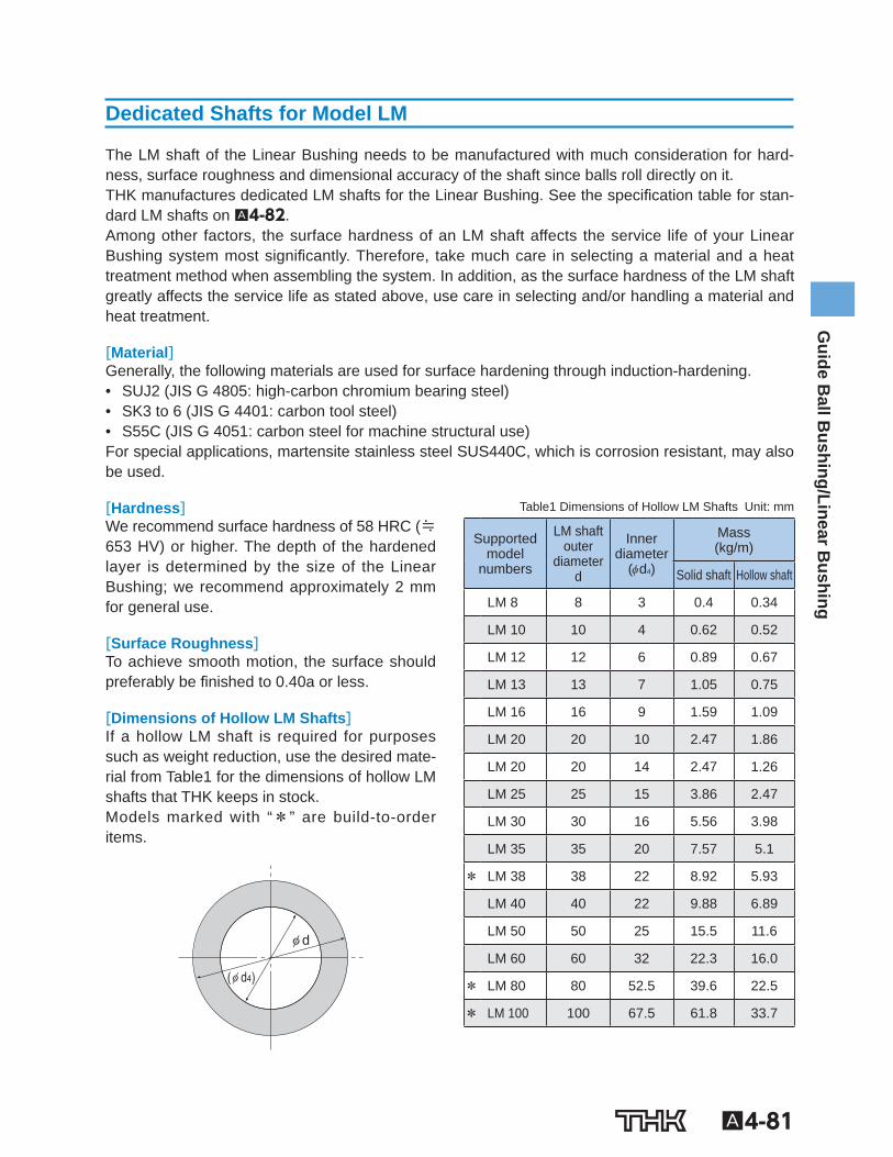
Dedicated Shafts for Model LM
The LM shaft of the Linear Bushing needs to be manufactured with much consideration for hard-ness, surface roughness and dimensional accuracy of the shaft since balls roll directly on it. THK manufactures dedicated LM shafts for the Linear Bushing. See the speci cation table for stan-dard LM shafts on A4-82 . Among other factors, the surface hardness of an LM shaft affects the service life of your Linear Bushing system most signi cantly. Therefore, take much care in selecting a material and a heat treatment method when assembling the system. In addition, as the surface hardness of the LM shaft greatly affects the service life as stated above, use care in selecting and/or handling a material and heat treatment.
[Material] Generally, the following materials are used for surface hardening through induction-hardening. • SUJ2 (JIS G 4805: high-carbon chromium bearing steel) • SK3 to 6 (JIS G 4401: carbon tool steel) • S55C (JIS G 4051: carbon steel for machine structural use) For special applications, martensite stainless steel SUS440C, which is corrosion resistant, may also be used.
[Hardness] We recommend surface hardness of 58 HRC (≒653 HV) or higher. The depth of the hardened layer is determined by the size of the Linear Bushing; we recommend approximately 2 mm for general use.
[Surface Roughness] To achieve smooth motion, the surface should preferably be nished to 0.40a or less.
[Dimensions of Hollow LM Shafts] If a hollow LM shaft is required for purposes such as weight reduction, use the desired mate-rial from Table1 for the dimensions of hollow LM shafts that THK keeps in stock. Models marked with “*” are build-to-order items.
φ d
(φ d4)
Table1 Dimensions of Hollow LM Shafts Unit: mm
Supportedmodel
numbers
LM shaft outer
diameter d
Innerdiameter
( d 4 )
Mass (kg/m)
Solid shaft Hollow shaft
LM 8 8 3 0.4 0.34
LM 10 10 4 0.62 0.52
LM 12 12 6 0.89 0.67
LM 13 13 7 1.05 0.75
LM 16 16 9 1.59 1.09
LM 20 20 10 2.47 1.86
LM 20 20 14 2.47 1.26
LM 25 25 15 3.86 2.47
LM 30 30 16 5.56 3.98
LM 35 35 20 7.57 5.1
* LM 38 38 22 8.92 5.93
LM 40 40 22 9.88 6.89
LM 50 50 25 15.5 11.6
LM 60 60 32 22.3 16.0
* LM 80 80 52.5 39.6 22.5
* LM 100 100 67.5 61.8 33.7
Model number coding
A4-82
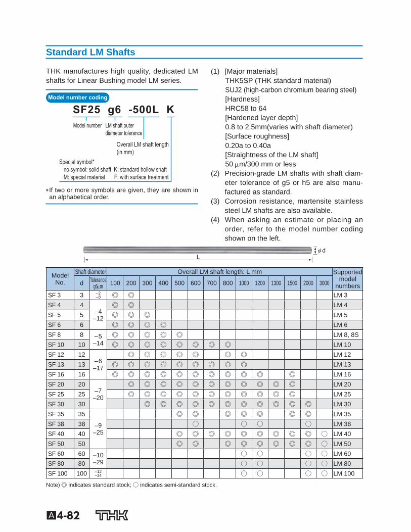
Standard LM Shafts
THK manufactures high quality, dedicated LM shafts for Linear Bushing model LM series.
Special symbol*no symbol: solid shaft K: standard hollow shaftM: special material F: with surface treatment
Overall LM shaft length(in mm)
LM shaft outerdiameter tolerance
Model number
SF25 g6 -500L K
If two or more symbols are given, they are shown in an alphabetical order.
(1) [Major materials] THK5SP (THK standard material) SUJ2 (high-carbon chromium bearing steel) [Hardness] HRC58 to 64 [Hardened layer depth] 0.8 to 2.5mm(varies with shaft diameter) [Surface roughness] 0.20a to 0.40a [Straightness of the LM shaft] 50 m/300 mm or less
(2) Precision-grade LM shafts with shaft diam-eter tolerance of g5 or h5 are also manu-factured as standard.
(3) Corrosion resistance, martensite stainless steel LM shafts are also available.
(4) When asking an estimate or placing an order, refer to the model number coding shown on the left.
φ dL
Model No.
Shaft diameter Overall LM shaft length: L mm Supportedmodel
numbers d Tolerance g6 m 100 200 300 400 500 600 700 800 1000 1200 1300 1500 2000 3000
SF 3 3 –2 –8 ◎ ◎ LM 3
SF 4 4 –4 –12
◎ ◎ LM 4 SF 5 5 ◎ ◎ ◎ LM 5 SF 6 6 ◎ ◎ ◎ ◎ LM 6 SF 8 8 –5
–14 ◎ ◎ ◎ ◎ ◎ LM 8, 8S
SF 10 10 ◎ ◎ ◎ ◎ ◎ ◎ ◎ ◎ LM 10 SF 12 12
–6 –17
◎ ◎ ◎ ◎ ◎ ◎ ◎ LM 12 SF 13 13 ◎ ◎ ◎ ◎ ◎ ◎ ◎ ◎ ◎ LM 13 SF 16 16 ◎ ◎ ◎ ◎ ◎ ◎ ◎ ◎ ◎ ◎ ◎ LM 16 SF 20 20
–7 –20
◎ ◎ ◎ ◎ ◎ ◎ ◎ ◎ ◎ ◎ ◎ LM 20 SF 25 25 ◎ ◎ ◎ ◎ ◎ ◎ ◎ ◎ ◎ ◎ ◎ LM 25 SF 30 30 ◎ ◎ ◎ ◎ ◎ ◎ ◎ ◎ ◎ ◎ ◎ LM 30 SF 35 35
–9 –25
◎ ◎ ◎ ◎ ◎ ◎ ◎ LM 35 SF 38 38 ○ ○ ○ ○ LM 38 SF 40 40 ◎ ◎ ◎ ◎ ◎ ◎ ◎ ◎ ◎ ○ LM 40 SF 50 50 ◎ ◎ ◎ ◎ ◎ ◎ ◎ ◎ ○ LM 50 SF 60 60 –10
–29 ○ ○ ○ ○ LM 60
SF 80 80 ○ ○ ○ ○ LM 80 SF 100 100 –12
–34 ○ ○ ○ ○ LM 100
Note) ◎ indicates standard stock; ○ indicates semi-standard stock.
A4-83
Guide B
all Bushing/Linear B
ushing
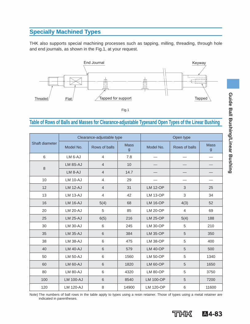
Specially Machined Types
THK also supports special machining processes such as tapping, milling, threading, through hole and end journals, as shown in the Fig.1 , at your request.
Tapped for support Tapped
Keyway End Journal
Flat Threaded
Fig.1
Table of Rows of Balls and Masses for Clearance-adjustable Typesand Open Types of the Linear Bushing
Shaft diameter Clearance-adjustable type Open type
Model No. Rows of balls Mass g Model No. Rows of balls Mass
g
6 LM 6-AJ 4 7.8 — — —
8 LM 8S-AJ 4 10 — — —
LM 8-AJ 4 14.7 — — —
10 LM 10-AJ 4 29 — — —
12 LM 12-AJ 4 31 LM 12-OP 3 25
13 LM 13-AJ 4 42 LM 13-OP 3 34
16 LM 16-AJ 5(4) 68 LM 16-OP 4(3) 52
20 LM 20-AJ 5 85 LM 20-OP 4 69
25 LM 25-AJ 6(5) 216 LM 25-OP 5(4) 188
30 LM 30-AJ 6 245 LM 30-OP 5 210
35 LM 35-AJ 6 384 LM 35-OP 5 350
38 LM 38-AJ 6 475 LM 38-OP 5 400
40 LM 40-AJ 6 579 LM 40-OP 5 500
50 LM 50-AJ 6 1560 LM 50-OP 5 1340
60 LM 60-AJ 6 1820 LM 60-OP 5 1650
80 LM 80-AJ 6 4320 LM 80-OP 5 3750
100 LM 100-AJ 6 8540 LM 100-OP 5 7200
120 LM 120-AJ 8 14900 LM 120-OP 6 11600
Note) The numbers of ball rows in the table apply to types using a resin retainer. Those of types using a metal retainer are indicated in parentheses.
A4-84
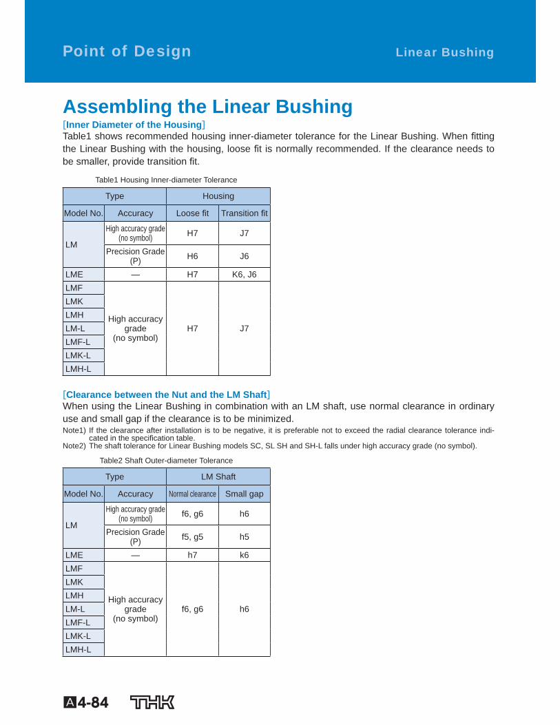
Assembling the Linear Bushing [Inner Diameter of the Housing] Table1 shows recommended housing inner-diameter tolerance for the Linear Bushing. When tting the Linear Bushing with the housing, loose t is normally recommended. If the clearance needs to be smaller, provide transition t.
Table1 Housing Inner-diameter Tolerance
Type Housing
Model No. Accuracy Loose t Transition t
LM
High accuracy grade(no symbol) H7 J7
Precision Grade (P) H6 J6
LME — H7 K6, J6 LMF
High accuracygrade
(no symbol) H7 J7
LMK LMH LM-L LMF-L LMK-L LMH-L
[Clearance between the Nut and the LM Shaft] When using the Linear Bushing in combination with an LM shaft, use normal clearance in ordinary use and small gap if the clearance is to be minimized. Note1) If the clearance after installation is to be negative, it is preferable not to exceed the radial clearance tolerance indi-
cated in the speci cation table. Note2) The shaft tolerance for Linear Bushing models SC, SL SH and SH-L falls under high accuracy grade (no symbol).
Table2 Shaft Outer-diameter Tolerance
Type LM Shaft
Model No. Accuracy Normal clearance Small gap
LM
High accuracy grade(no symbol) f6, g6 h6
Precision Grade (P) f5, g5 h5
LME — h7 k6 LMF
High accuracygrade
(no symbol) f6, g6 h6
LMK LMH LM-L LMF-L LMK-L LMH-L
Linear Bushing Point of Design
A4-85
Guide B
all Bushing/Linear B
ushing
[Mounting the Nut] Although the Linear Bushing does not require a large amount of strength for securing it in the axial direction, do not rely only on a press t to support the nut. For the housing inner-diameter tolerance, see Table1 on A4-84 .
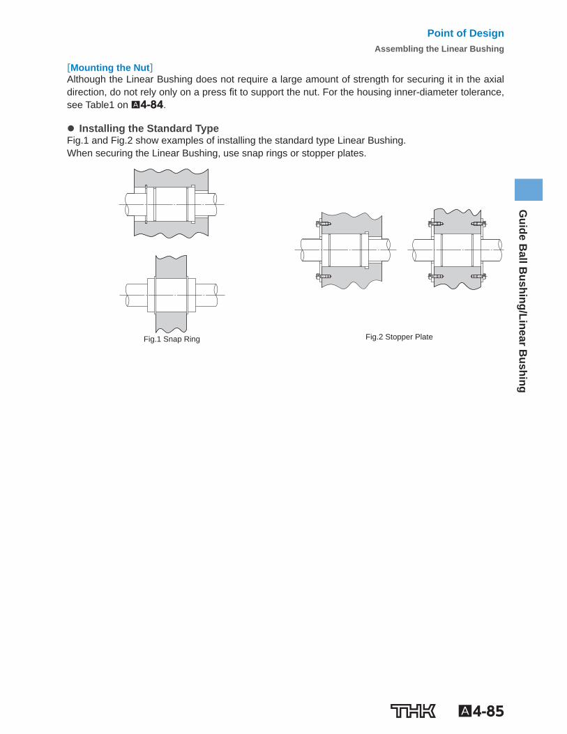
Installing the Standard Type Fig.1 and Fig.2 show examples of installing the standard type Linear Bushing. When securing the Linear Bushing, use snap rings or stopper plates.
Fig.1 Snap Ring
Fig.2 Stopper Plate
Point of DesignAssembling the Linear Bushing
A4-86
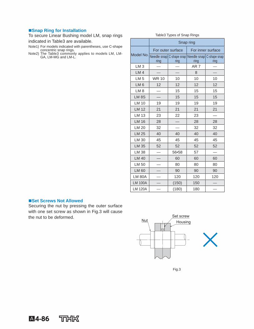
Snap Ring for Installation To secure Linear Bushing model LM, snap rings indicated in Table3 are available. Note1) For models indicated with parentheses, use C-shape
concentric snap rings. Note2) The Table3 commonly applies to models LM, LM-
GA, LM-MG and LM-L.
Table3 Types of Snap Rings
Snap ring
Model No. For outer surface For inner surface
Needle snap ring
C-shape snap ring
Needle snap ring
C-shape snap ring
LM 3 — — AR 7 — LM 4 — — 8 — LM 5 WR 10 10 10 10 LM 6 12 12 12 12 LM 8 — 15 15 15
LM 8S — 15 15 15 LM 10 19 19 19 19 LM 12 21 21 21 21 LM 13 23 22 23 — LM 16 28 — 28 28 LM 20 32 — 32 32 LM 25 40 40 40 40 LM 30 45 45 45 45 LM 35 52 52 52 52 LM 38 — 56•58 57 — LM 40 — 60 60 60 LM 50 — 80 80 80 LM 60 — 90 90 90
LM 80A — 120 120 120 LM 100A — (150) 150 — LM 120A — (180) 180 —
Set Screws Not Allowed Securing the nut by pressing the outer surface with one set screw as shown in Fig.3 will cause the nut to be deformed.
Nut Set screw
Housing
Fig.3
A4-87
Guide B
all Bushing/Linear B
ushing
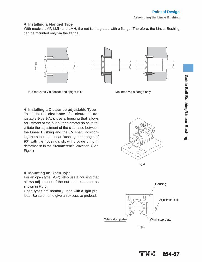
Installing a Flanged Type With models LMF, LMK and LMH, the nut is integrated with a ange. Therefore, the Linear Bushing can be mounted only via the ange.
Nut mounted via socket and spigot joint Mounted via a flange only
Installing a Clearance-adjustable Type To adjust the clearance of a clearance-ad-justable type (-AJ), use a housing that allows adjustment of the nut outer diameter so as to fa-cilitate the adjustment of the clearance between the Linear Bushing and the LM shaft. Position-ing the slit of the Linear Bushing at an angle of 90 with the housing’s slit will provide uniform deformation in the circumferential direction. (See Fig.4 .)
Fig.4
Mounting an Open Type For an open type (-OP), also use a housing that allows adjustment of the nut outer diameter as shown in Fig.5 . Open types are normally used with a light pre-load. Be sure not to give an excessive preload.
Whirl-stop plate Whirl-stop plate
Housing
Adjustment bolt
Fig.5
Point of DesignAssembling the Linear Bushing
A4-88
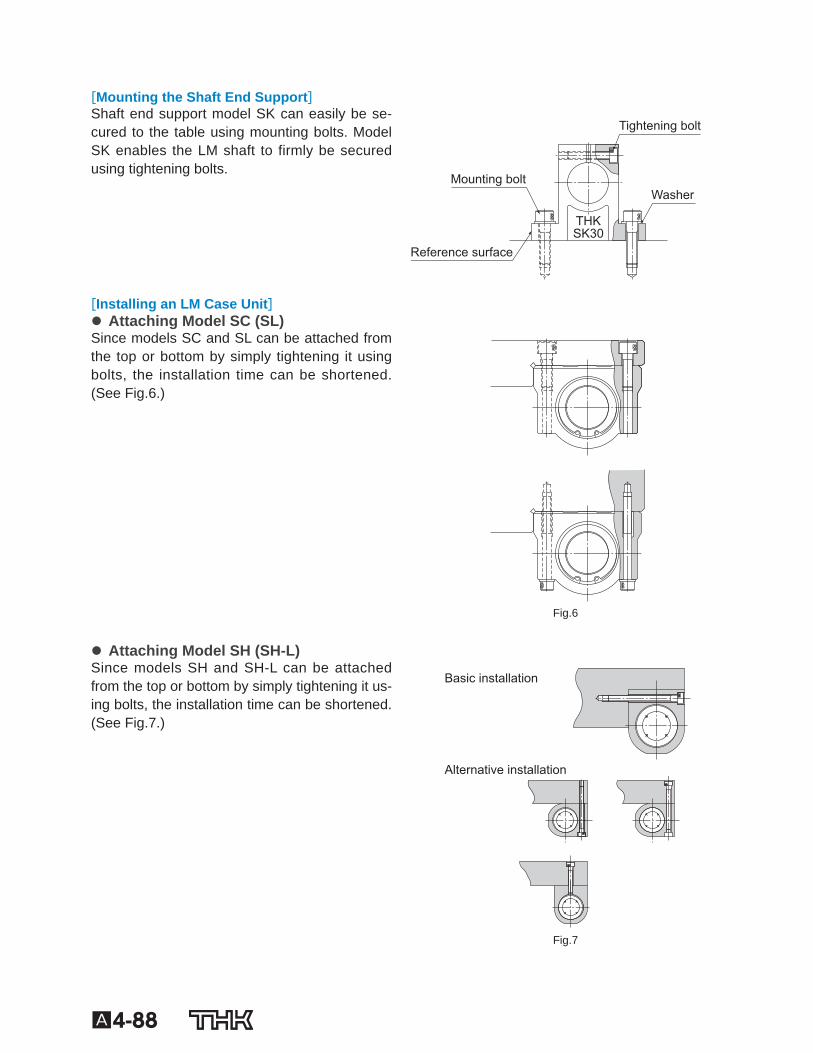
[Mounting the Shaft End Support] Shaft end support model SK can easily be se-cured to the table using mounting bolts. Model SK enables the LM shaft to firmly be secured using tightening bolts.
Tightening bolt
Mounting bolt Washer
Reference surface
THK SK30
[Installing an LM Case Unit]
Attaching Model SC (SL) Since models SC and SL can be attached from the top or bottom by simply tightening it using bolts, the installation time can be shortened. (See Fig.6 .)
Fig.6
Attaching Model SH (SH-L) Since models SH and SH-L can be attached from the top or bottom by simply tightening it us-ing bolts, the installation time can be shortened.(See Fig.7 .)
Alternative installation
Basic installation
Fig.7
A4-89
Guide B
all Bushing/Linear B
ushing
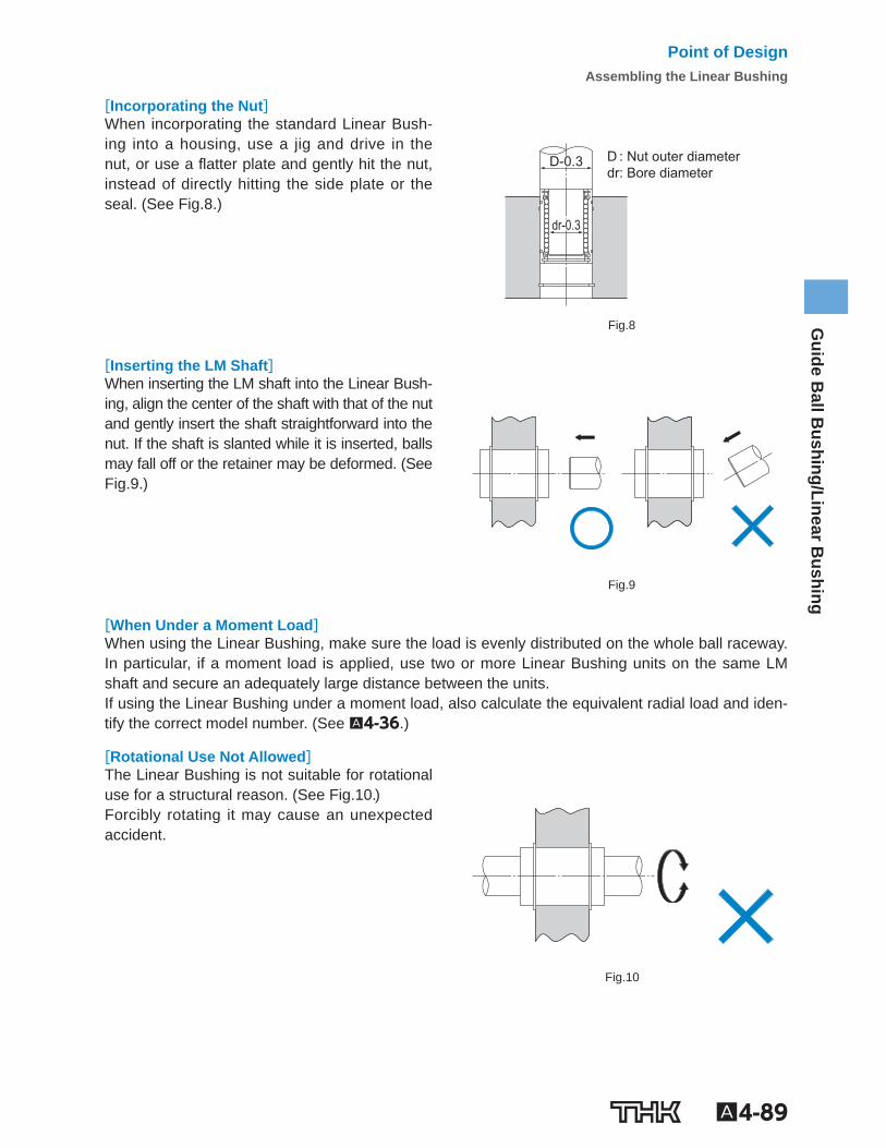
[Incorporating the Nut] When incorporating the standard Linear Bush-ing into a housing, use a jig and drive in the nut, or use a atter plate and gently hit the nut, instead of directly hitting the side plate or the seal. (See Fig.8 .)
D : Nut outer diameter dr: Bore diameter
D-0.3
dr-0.3
Fig.8
[Inserting the LM Shaft] When inserting the LM shaft into the Linear Bush-ing, align the center of the shaft with that of the nut and gently insert the shaft straightforward into the nut. If the shaft is slanted while it is inserted, balls may fall off or the retainer may be deformed. (See Fig.9 .)
Fig.9
[When Under a Moment Load] When using the Linear Bushing, make sure the load is evenly distributed on the whole ball raceway. In particular, if a moment load is applied, use two or more Linear Bushing units on the same LM shaft and secure an adequately large distance between the units. If using the Linear Bushing under a moment load, also calculate the equivalent radial load and iden-tify the correct model number. (See A4-36 .)
[Rotational Use Not Allowed] The Linear Bushing is not suitable for rotational use for a structural reason. (See Fig.10 .) Forcibly rotating it may cause an unexpected accident.
Fig.10
Point of DesignAssembling the Linear Bushing
A4-90
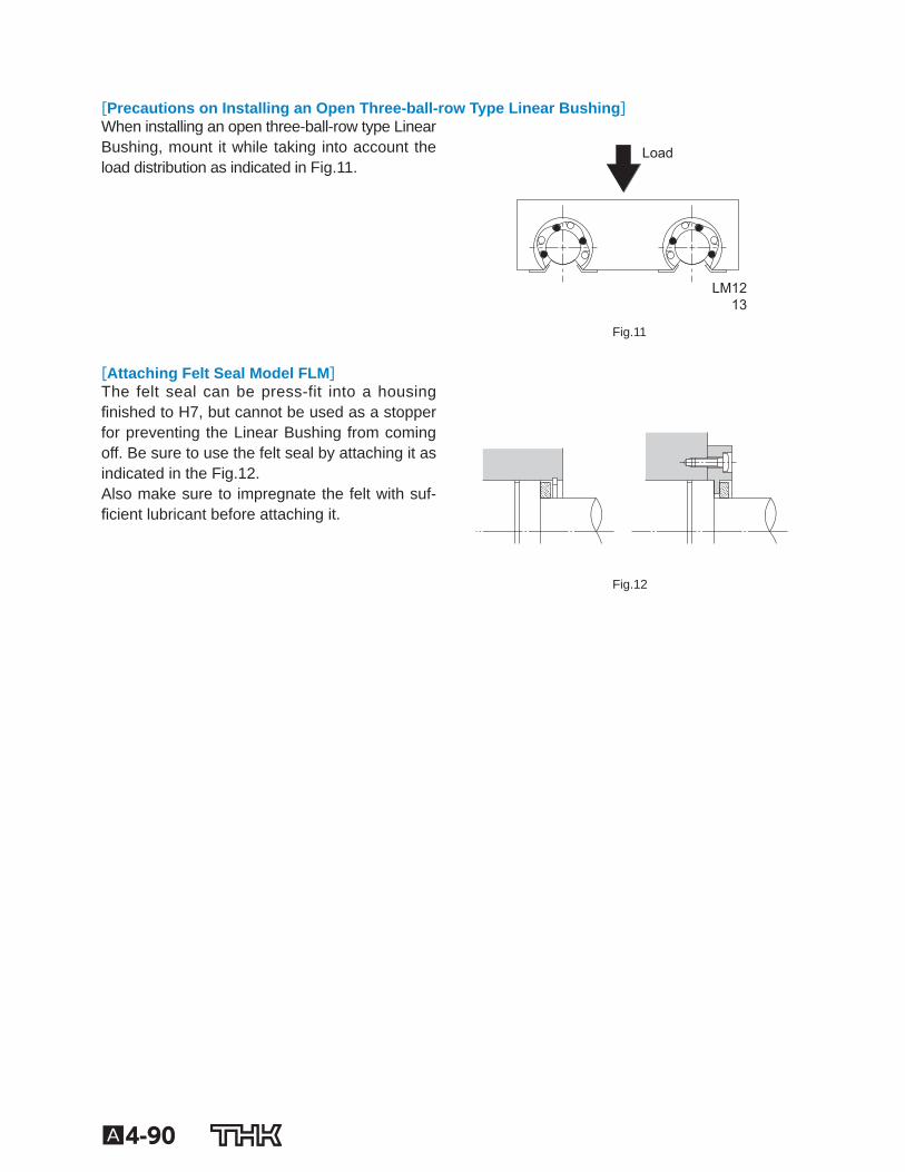
[Precautions on Installing an Open Three-ball-row Type Linear Bushing] When installing an open three-ball-row type Linear Bushing, mount it while taking into account the load distribution as indicated in Fig.11 .
Load
LM1213
Fig.11
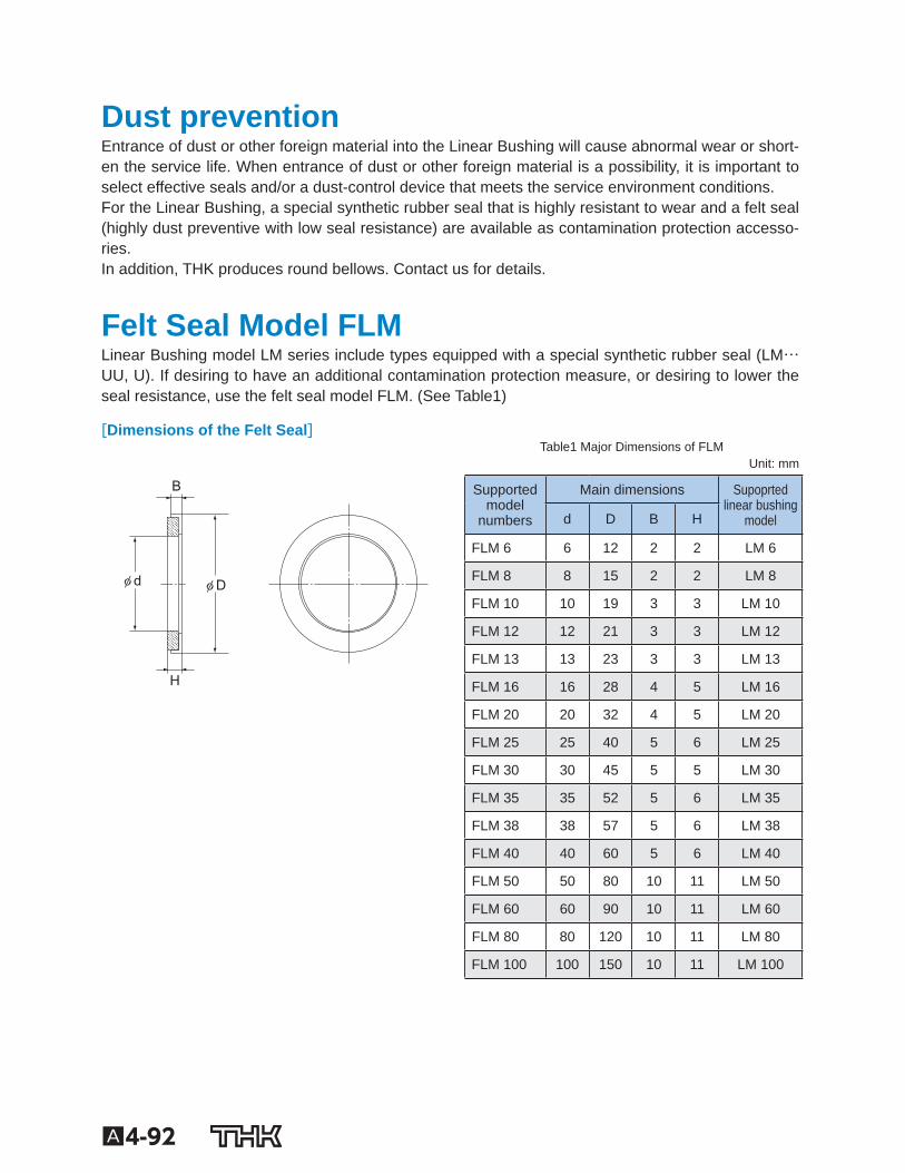
[Attaching Felt Seal Model FLM] The felt seal can be press-fit into a housing nished to H7, but cannot be used as a stopper for preventing the Linear Bushing from coming off. Be sure to use the felt seal by attaching it as indicated in the Fig.12 . Also make sure to impregnate the felt with suf- cient lubricant before attaching it.
Fig.12
A4-91
Guide B
all Bushing/Linear B
ushing
Lubrication The Linear Bushing requires grease or oil as a lubricant for its operation.
[Grease Lubrication] When installing a type attached with seals on both sides (…UU) to the LM shaft, apply grease to rows of balls in the Linear Bushing. When installing standard types (without seal), perform the same as above or apply grease to the LM shaft. Afterward, replenish grease of the same type as necessary according to the service conditions. We recommend using high-quality lithium-soap group grease No. 2.
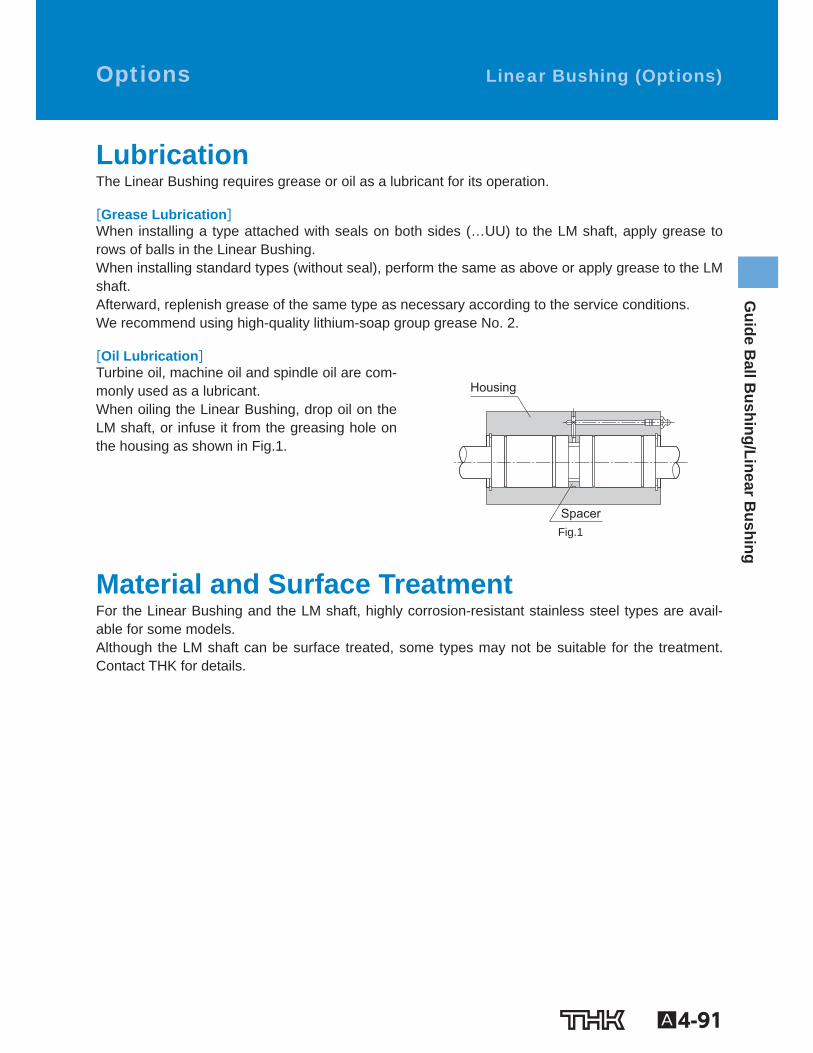
[Oil Lubrication] Turbine oil, machine oil and spindle oil are com-monly used as a lubricant. When oiling the Linear Bushing, drop oil on the LM shaft, or infuse it from the greasing hole on the housing as shown in Fig.1 .
Housing
Spacer Fig.1
Material and Surface Treatment For the Linear Bushing and the LM shaft, highly corrosion-resistant stainless steel types are avail-able for some models. Although the LM shaft can be surface treated, some types may not be suitable for the treatment. Contact THK for details.
Linear Bushing (Options) Options
A4-92
Dust prevention Entrance of dust or other foreign material into the Linear Bushing will cause abnormal wear or short-en the service life. When entrance of dust or other foreign material is a possibility, it is important to select effective seals and/or a dust-control device that meets the service environment conditions. For the Linear Bushing, a special synthetic rubber seal that is highly resistant to wear and a felt seal (highly dust preventive with low seal resistance) are available as contamination protection accesso-ries. In addition, THK produces round bellows. Contact us for details.
Felt Seal Model FLM Linear Bushing model LM series include types equipped with a special synthetic rubber seal (LM…UU, U). If desiring to have an additional contamination protection measure, or desiring to lower the seal resistance, use the felt seal model FLM. (See Table1 )
[Dimensions of the Felt Seal]
B
φ Dφ d
H
Table1 Major Dimensions of FLM Unit: mm
Supportedmodel
numbers
Main dimensions Supoprtedlinear bushing
model d D B H
FLM 6 6 12 2 2 LM 6
FLM 8 8 15 2 2 LM 8
FLM 10 10 19 3 3 LM 10
FLM 12 12 21 3 3 LM 12
FLM 13 13 23 3 3 LM 13
FLM 16 16 28 4 5 LM 16
FLM 20 20 32 4 5 LM 20
FLM 25 25 40 5 6 LM 25
FLM 30 30 45 5 5 LM 30
FLM 35 35 52 5 6 LM 35
FLM 38 38 57 5 6 LM 38
FLM 40 40 60 5 6 LM 40
FLM 50 50 80 10 11 LM 50
FLM 60 60 90 10 11 LM 60
FLM 80 80 120 10 11 LM 80
FLM 100 100 150 10 11 LM 100
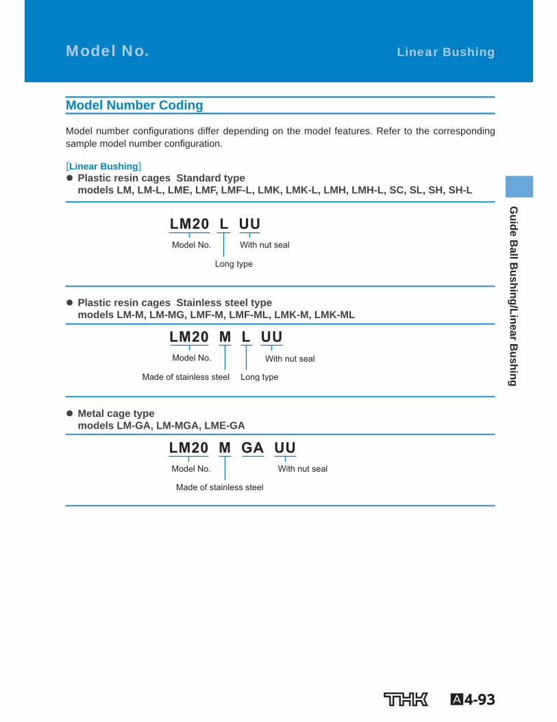
A4-93
Guide B
all Bushing/Linear B
ushing
Model Number Coding
Model number con gurations differ depending on the model features. Refer to the corresponding sample model number con guration.
[Linear Bushing] Plastic resin cages Standard typemodels LM, LM-L, LME, LMF, LMF-L, LMK, LMK-L, LMH, LMH-L, SC, SL, SH, SH-L
Model No. With nut seal
Long type
LM20 L UU
Plastic resin cages Stainless steel typemodels LM-M, LM-MG, LMF-M, LMF-ML, LMK-M, LMK-ML
Model No.
Made of stainless steel Long type
With nut seal
LM20 M L UU
Metal cage typemodels LM-GA, LM-MGA, LME-GA
Model No.
Made of stainless steel
With nut seal
LM20 M GA UU
Linear Bushing Model No.
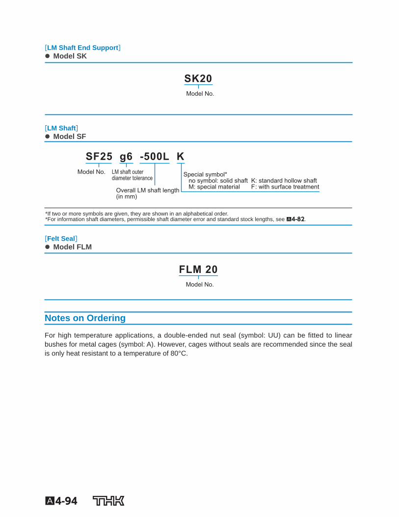
A4-94
[LM Shaft End Support] Model SK
Model No.
SK20
[LM Shaft] Model SF
Special symbol*no symbol: solid shaft K: standard hollow shaftM: special material F: with surface treatmentOverall LM shaft length
(in mm)
LM shaft outer diameter tolerance
Model No.
SF25 g6 -500L K
* If two or more symbols are given, they are shown in an alphabetical order. * For information shaft diameters, permissible shaft diameter error and standard stock lengths, see A4-82 .
[Felt Seal] Model FLM
Model No.
FLM 20
Notes on Ordering
For high temperature applications, a double-ended nut seal (symbol: UU) can be fitted to linear bushes for metal cages (symbol: A). However, cages without seals are recommended since the seal is only heat resistant to a temperature of 80°C.
A4-95
Guide B
all Bushing/Linear B
ushing Precautions on Use Linear Bushing
[Handling] (1) Disassembling components may cause dust to enter the system or degrade mounting accuracy
of parts. Do not disassemble the product. (2) Dropping or hitting the Linear Bushing may damage it. Giving an impact force to the product
could also cause damage even if the product looks intact.
[Lubrication] (1) Thoroughly remove anti-rust oil and feed lubricant before using the product. (2) Do not mix lubricants of different physical properties. (3) In locations exposed to constant vibrations or in special environments such as clean rooms,
vacuum and low/high temperature, normal lubricants may not be used. Contact THK for details. (4) When planning to use a special lubricant, contact THK before using it.
[Precautions on Use] (1) Entrance of foreign material may cause damage to the ball circulating component or functional
loss. Prevent foreign material, such as dust or cutting chips, from entering the system. (2) Do not use the product at temperature of 80℃ or higher. Contact THK if you desire to use the
product at a temperature of 80℃ or higher. (3) Please be careful when using the product in an environment with excessive coolant. The coolant
may cause premature failure if it penetrates the Linear Bushing. Contact THK for further details. (4) If foreign material adheres to the product, replenish the lubricant after cleaning the product. (5) When using the product in locations exposed to constant vibrations or in special environments
such as clean rooms, vacuum and low/high temperature, contact THK in advance.
[Storage] When storing the Linear Bushing, enclose it in a package designated by THK and store it while avoiding high temperature, low temperature and high humidity.

A4-96