

WELLENKUPPLUNGEN - Enemac · ENEMAC. de [email protected] ENEMAC. org Wellenkupplungen / Shaft...
47
Transcript of WELLENKUPPLUNGEN - Enemac · ENEMAC. de [email protected] ENEMAC. org Wellenkupplungen / Shaft...
EN
EM
AC
.de info
@enem
ac.d
e
EN
EM
AC
.org
sale
s@
enem
ac.d
e
Wellenkupplungen / Shaft couplings
Metallbalgkupplung EWA
metal bellows coupling EWA
7-17
11
Inhalt / content:Seite / page
Metallbalgkupplung EWB
metal bellows coupling EWB
Metallbalgkupplung EWF
metal bellows coupling EWF
12
13
14
15
Metallbalgkupplung EWC
metal bellows coupling EWC
Metallbalgkupplung EWG
metal bellows coupling EWG
Metallbalgkupplung EWH
metal bellows coupling EWH
Metallbalgkupplung EWHL
metal bellows coupling EWHL
Metallbalgkupplung EWI
metal bellows coupling EWI
Metallbalgkupplung EWM
metal bellows coupling EWM
16
17
18
19 + 20
Metallbalgkupplung EWP
metal bellows coupling EWP
Metallbalgkupplung EWS
metal bellows coupling EWS
Metallbalgkupplung EWU
metal bellows coupling EWU
Metallbalgkupplung EWMH/EWPH/EWRH
metal bellows coupling EWMH/EWPH/EWRH
21
22
23
24
Wellenkupplungen allgemein shaft couplings in general
Wellenkupplungen - Auslegung shaft coupling - dimensio-
ning
4
5 + 6 + 7
8
9 + 10
Wellenkupplungen - Montage shaft coupling - installation
Metallbalgkupplungen - Technik metal bellows coupling -
technology

EN
EM
AC
.de info
@enem
ac.d
e
EN
EM
AC
.org
sale
s@
enem
ac.d
e
Wellenkupplungen / Shaft couplings
Distanzkupplung allgemein distance coupling in general
20-18
30
Inhalt / content: Seite / page
Miniaturkupplungen allgemein miniature couplings in general
Miniatur Metallbalgkupplung EWA
miniature metal bellows coupling EWA
31
33
34
35
Miniatur Metallbalgkupplung EWB
miniature metal bellows coupling EWB
Miniatur Metallbalgkupplung EWKA
miniature metal bellows coupling EWKA
Miniatur Elastomerkupplung EWJT/EWJTC
miniature jaw coupling EWJT/EWJTC
Miniatur Kreuzschieberkupplung EWOH/EWOHC
miniature oldham coupling EWOH/EWOHC
36
37
Elastomerkupplungen allgemein jaw couplings in general
Elastomerkupplungen - Auslegung jaw couplings - dimensi-
oning
25
26 + 27
28
29
Elastomerkupplung EWD
jaw coupling EWD
Elastomerkupplung EWE
jaw coupling EWE
Lamellenkupplung EWZL
disc coupling EWZL
38
39
Lamellenkupplung EWZK
disc coupling EWZK
Distanzkupplung EWL
distance coupling EWL
Distanzkupplung EWLH
distance coupling EWLH
Distanzkupplung EWLM
distance coupling EWLM
Distanzkupplung EWLA
distance coupling EWLA
Distanzkupplung EWLC
distance coupling EWLC
40
41
42
45
46
Elastomerkupplung EWN
jaw coupling EWN
32
Lamellenkupplungen disc couplings 43 + 44

Wellenkupplungen allgemein Shaft couplings in generalENEMAC.d
e in
fo@
enem
ac.
de
ENEMAC.o
rg
sale
s@enem
ac.
de
10-17
Definition Wellenkupplung:
Wellenkupplungen sind Ausgleichskupplungen zur spielfreien, winkel-getreuen Übertragung von Drehmomenten mit einer möglichst hohen Verdrehsteifigkeit (Torsionssteife) und einem möglichst niedrigen Massenträgheitsmoment. Gemäß diesem Anspruch können die ENEMAC-Metallbalgkupplungen als Ideallösung betrachtet werden. Sie haben sich bereits seit mehr als 30 Jahren in Tausenden von Servoantrieben hervorragend bewährt. Aber auch die Elastomerkupp-lungen mit einem flexiblen Polyurethanstern können aufgrund ihrer produktspezifischen Vorteile für viele Anwendungen eine sinnvolle Alternative darstellen. Allen ENEMAC-Wellenkupplungen gemeinsam ist die absolute Spielfreiheit (auch Welle-Nabe-Verbindung) und die Flexibilität zum Ausgleich von Wellenversatz. Die Einsatzgebiete reichen von hochdynamischen Vorschubachsen in Werkzeugmaschi-nen bis zu anspruchsvollen Antrieben im allgemeinen Maschinenbau.
Definition shaft couplings:
Shaft couplings are compensating couplings with a zero backlash and conformal torque transfer providing high torsional stiffness and a low moment of inertia. According to these requirements, our bellows couplings can be regarded as the ideal solution. More than 30 years, they have proven themselves in thousands of servo drives as being excellent. Jaw couplings with a flexible polyurethane insert can also represent a perfect alternative for different applications because of their product-specific advantages. ENEMAC shaft couplings have one thing in common, they are backlash-free (also shaft-hub-connec-tion) and flexible to allow the compnesation of shaft misalignments. Because of the unique characteristics of the different series, the designer will find the best solution within the large-scale of our range of couplings. The field of application ranges from highly dynamic feed drives of the axis of machine tools to high performance drives in the general machine tool design.
Leistungsmerkmale - Wellenkupplungen:
• absolut spielfreie, exakte Drehmomentübertragung• niedrige Massenträgheitsmomente - hohe Wuchtgüte• hervorragendes Betriebsverhalten - hohe Drehzahlen• Ausgleich von Fluchtungsfehlern - geringe Rückstellkräfte• kraftschlüssige, montagefreundliche Welle-Nabe-Verbindung• Metallbalg: maximale Torsionssteife, verschleißfrei, bis 350 °C• Elastomerstern: steckbar, schwingungsdämpfend, bis 120 °C• kompakte Abmessungen, flexible Anwendungsmöglichkeiten• umfangreiche Typen- und Größenauswahl• präzise Teilefertigung - beste Produktqualität - lange Lebens-
dauer
Characteristics - shaft couplings:
• zero backlash, exact torque transfer• low moment of inertia - high balancing quality• excellent operational characteristics - high speed• compensation of shaft misalignments - low restoring forces• frictional, easy to fit shaft-hub-connection• metal bellows: max. torisional rigidity, wear free, up to 623 K• polyurethane insert: plug-in, oscillation dampening, up to • 393 K• compact - flexible fields of application• large number of types and sizes available• precise production - best quality - long life time
VergleichMetallbalg-kupplung
Elastomer-kupplung
wesentliche Funktionsmerkmale
• sehr hohe Ver-drehsteifigkeit, dadurch exakte Drehwinkel-übertragung
• geringes Mas-senträgheitsmo-ment
• minimale Rück-stellkräfte auf Lager
• steckbar (Blindmontage möglich)
• schwingungs-dämpfend
• spielfrei durch Vrospannung des Kupplungs-sterns in den Klauen
Verbindungs- bzw. Ausgleichselement
Metallbalg aus Edelstahl
Elastomerstern aus Polyurethan
Nabenausführung
• montage-freundliche Klemmnaben (kraftschlüssig, spielfrei)
• Konus-Klemm-nabe
• Spreizkonus-nabe
• geteilte Nabe• Flansch• Schrumpfschei-
be
• montagefreund-liche Klemm-naben
• Konusver-bindung mit Spannringnabe
Temperaturbereich bis max. 300 °C bis max. 120 °C
Drehzahlen
• Kupplungen sind vorge-wuchtet
• für Drehzahlen oberhalb von ca. 5.000 min-1
ist zusätzliches Auswuchten empfehlenswert
Ausführung mit Spannringnabe Typ EWE ist für höchste Drehzahlen bis 20.000 min-1 geeignet
ComparisonMetal bellows
couplingJaw coupling
essential features
• high torsional stiffness
• low moment of inertia
• minimial resto-ring force onto the bearing
• pluggable (allows blind assembly)
• vibration absor-bing
• zero backlash due to initial load of the claws
element of balancemetal bellows made of stainless steel
polyurethane insert
features of the hub
• easy assembly clamping hub (non-positive connection, zero backlash)
• conical clam-ping hub
• expansion cone hub
• flange• shrink disc
• easy assemply clamping hub
• conical hub
temperature range up to 623 K up to 393 K
rotational speed
• couplings are prebalanced
• for speeds over 5.000 rpm counterbalan-cing is recom-mendable
type EWE with co-nical hubs qualified for high speed up to 20.000 rpm

Wellenkupplungen - Auslegung Shaft couplings - DimensioningE
NE
MA
C.d
e info
@enem
ac.
de
EN
EM
AC
.org
sale
s@enem
ac.
de
20-17
1.) Kupplungs-Nennmoment: TKN
- [Nm]
Das Nennmoment der Kupplungen gibt die Grenzbelastung der Dauerwechselfestigkeit an. Wird im Normalbetrieb T
KN
nicht überschritten, können unendlich viele Arbeitszyklen aus-geführt werden (s. auch „Kupplungs-Lebensdauer“).
2.) Massenträgheitsmoment: JK - [10-3 kgm2]
Die Kupplungswerte für das Massenträgheitsmoment gelten für mittlere Nabenbohrungen im angegebenen Druchmesser-berich D
min / D
max.
Umrechnung: [kgcm2] = [10-4 kgm2]
3.)Torsionssteifigkeit:CTK-[Nm/arcmin]
Bei der Angabe der spezifischen Torsionswerte (Verdrehstei-figkeit) aller Kupplungsbaureihen wurde eine Umstellung von der bisherigen Einheitsangabe [103 Nm/rad], auf die Einheit „Newtonmeter pro Winkelminute“ vorgenommen.Dadurch wird dem Konstrukteur recht einfach ermöglicht anhand des Betriebsdrehmomentes die entsprechenden Ver-drehwinkelfehler zu ermitteln (s. „b“). 60 Winkelminuten (bzw. Bogenminuten) entsprechen einem Winkelgrad. Hieraus ergibt sich folgender Umrechnungsfaktor:
1 rad = 57,3° = 3438 arcmin
[103 Nm/rad=0,291Nm/arcmin]bzw.[1Nm/arcmin=3438Nm/rad]
Beispiel: Größe EWA 170: 17,5 Nm/arcmin = 60 kNm/rad
4.)MaximalerWellenversatz:[mm]
Größtmaß der zulässigen Fluchtungsfehler zwischen An- und Abtriebswelle resultierend aus der Dauerwechselfestigkeits-berechnung für die Ausgleichsele-mente. Bei Betrieb unterhalb der zulässigen Versatzwerte können unendlich viele Lastwechsel aus-geführt werden. In Ausnahmefällen (z. B. Montage) bzw. bei reduzier-ten Lastwechselzahlen dürfen die Versatzwerte zum Teil deutlich höher liegen (bitte Rücksprache).
4.1)Axialversatz:
Meist unproblematisch (Wärmeausdehnung)
4.2)Winkelversatz:
Meist unproblematisch - zulässiger Maximalwert ist 1 bis 2 Grad.
4.3)Lateral-bzw.Paralellversatz:
Bei deutlicher Überschreitung des zulässigen Versatzwertes können Dauerbrüche an den Balgwellen bzw. übermäßiger Verschleiß des Elastomersterns auftreten. Bei Montage beson-ders beachten!
1.) Nominal torque of the coupling: TKN - [Nm]
The nominal torque of the coupling defines the max. load of the prolonged alternating-stress strength. If in normal operati-on T
KN is not exceeded, an infinite number of peration cycles
can be carried out (see „lifetime of the coupling“).
2.) Moment of inertia: JK - [10-3 kgm2]
The values for the moment of inertia are defined for medium hub-bores in the given diameter range D
min / D
max.
Conversion: [kgcm2] = 10-4 kgm2]
3.)Torsionalrigidity:CTK-[Nm/arcmin]
The values for the specific torsional rigidity of all couplings series are conversed from the existing values [103 Nm/rad] to „Newtonmeter per angular minute“. This enables the constructor to determine the twisting angle failure quite easily (see „b“) under consideration of the operating torque. 60 an-gular minutes (resp. arc minutes) correspond to one angular degree. This defines the conversion factor:
1 rad = 57,3° = 3438 arcmin
[103 Nm/rad=0,291Nm/arcmin]bzw.[1Nm/arcmin=3438Nm/rad]
Example: Size EWA 170: 17,5 Nm/arcmin = 60 kNm/rad
4.) Max. alignment of shafts: [mm]
The maximum alignment of shafts is the largest allowed misalignment between drive shaft and output shaft, which
results from the calculation of the pro-longed alternating-stress strength for compensating elements. If the allowed displacement values are not exceeded, an infinite number of load alternations can be carried out. In exceptional cases (e. g. during fixing) resp. at reduced numbers of load alternations, the dis-placement values may be considerably higher (after consultation).
4.1) Axial displacement:
Usually without problems (expansion due to temperature)
4.2) Angular displacement:
Usually without problems - allowed max. value: 1 to 2 de-grees
4.3) Lateral or parallel displacement:
If the admissible values are considerably exceeded, per-manent distortion at the bellows resp. higher wear of the polyurethan insert can occur. Special care during fitting must be taken!
TechnischeDaten-Definition/Erläuterungen Technicalinformations-definitions/details
lateral
axial
angular
Wellenkupplungen - Auslegung Shaft couplings - DimensioningE
NE
MA
C.d
e info
@enem
ac.
de
EN
EM
AC
.org
sale
s@enem
ac.
de
20-17
a.) Nach dem Drehmoment
In der Regel wir die Kupplungsgröße aufgrund des Drehmomentes ausgewählt. Zur exakten Bestimmung des erforderlichen Antriebs-momentes sind meistens aufwendige Berechnungen durchzufüh-ren (s. Formelsammlung). Ist die Baugröße des Motors festgelegt, kann das erforderliche Kupplungsnennmoment überschlägig wie folgt ermittelt werden:
TKN
> 1,25 x TAmax
x i
TAmax
= Spitzendrehmoment des Motorsi = Über- bzw. Untersetzung des Zahnriementriebes bzw. Stirnrad-getriebes
b.) Nach der Torsionssteife:
Bei hohen Genauigkeitsansprüchen (Positionierung, Gebersys-tem) können Übertragungsfehler durch eine zu große elastische Verformung der Kupplung ein Auswahlkriterium darstellen. Der aus der Drehmomentbelastung resultierende Verdrehwinkel „αT“ läßt sich wie folgt berechnen:
TA
αT=CTK
[Bogenminuten] mit TA = Antriebsmoment [Nm] / CTK
= Torsions-steife der Kupplung [Nm / arcmin]
In seltenen Ausnahmefällen können bei Metallbalgkupplungen Resonanzerscheinungen auftreten (z. B. Pfeif- oder Brummton). In solchen Fällen sollte ein Kupplungstyp mit deutlich höherer Tor-sionssteife oder eine schwingungsdämpfende Elastomerkupplung zum Einsatz kommen.
c.) Nach dem Wellendurchmesser:
Grundsätzlich sollte nach der Festlegung des Kupplungstypes eine Überprüfung der vorgegebenen Wellendurchmesser mit dem zulässigen Durchmesserbereich (D
min / D
max) der Nabenbohrung
stattfinden. Falls der Wellendurchmesser in Relation zum Drehmo-ment überdimensioniert, d. h. größer als Dmax der Nabe ist, muss eine andere Kupplungstype oder Baugröße gewählt werden.
Hinweis: Nabenbohrungen kleiner als Dmin
sind möglich; eine sichere Übertragung des Nennmomentes ist jedoch nicht gewähr-leistet, d. h. eine Reduzierung von T
KN ist erforderlich.
d.) Lebensdauer der Kupplung
Die Lebensdauer der Ausgleichskupp-lungen wird im Wesentlichden durch die Höhe des Drehmomentes und den vorhandenen Wellenversätzen bzw. Fluchtungsfehlern bestimmt. Werden die zulässigen maximalen Werte für den Axial-, Lateral- und Winkelversatz nicht überschritten und liegt gleichzeitig das Betriebsdrehmoment unterhalb des Kupp-lungsnennmoments T
KN, befindet sich die
Kupplung im Bereich der Dauerwechsel-festigkeit. Dauerbetrieb rund um die Uhr ist möglich, bzw. es können unendlich viele Beschleunigungs- und Verzögerungsphasen ausgeführt werden, ohne dass ein betriebs-bedingter Ausfall der Kupplung zu erwarten ist.
a.) According to torque:
Usually the size of the coupling is chosen according to the torque. For exact determination of the necessary driving torque, difficult calculations are necessary (look at the formulary). If the size of the motor is fixed, the necessary nominal torque of the coupling can be calculated as follows:
TKN
> 1,25 x TAmax
x i
TAmax
= peak torque of the motori = transmission resp. reduction of the toothed belt drive resp. the spur-toothed wheel
b.) According to the torsional rigidity:
For applications with very precise requirements (position control, transmitter), transfer errors due to high elastic deformation can be an important criteria of selection of the coupling. The torsional angle „αT“ is calculated as follows:
TA
αT=CTK
[arc minutes] with TA = driving torque [Nm] / CTK
= torsional rigidity of the coupling [Nm/arcmin]
In very few cases, metal bellows couplings can have resonance sounds (e. g. a whistling or a humming). Then coupling types with a higher torsional rigidity or vibration reducing jaw couplings are recommended.
c.) According to the shaft diameter:
After selecting the coupling type, it has to be checked whether the requested shaft diameter corresponds with the allowed dia-meter (D
min / D
max) of the hub bores.
Another coupling type or size must be chosen, if the shaft dia-meter is overdimensiond in relation to the torque, which means it is larger than D
max of the hub.
Note: Hub bores which are smaller than Dmin
are possible; but an optimal transfer of the nominal torque can not be guaranteed in this case, so a reduction T
KN is necessary.
d.) Lifetime of the coupling - durabi-
lity:
The durability of our compensating couplings is basically determined by the peak torque and the existing shaft displacement or misalignment. If the admissible maximum values for the axial, lateral and angular displacement are not exceeded, and if the operating torque at the same time is below the coupling nominal torque T
KN, then the
coupling is within the range of prolonged alternatinstress strength limit. An infinite
number of start - stop - cycles or acceleration and deceleration can be carried out without having to expect a breakdown of the coupling during operation.
Kupplungsauslegung Dimensioning of the coupling
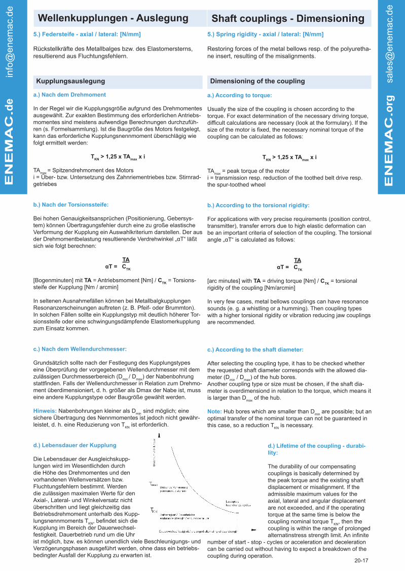
5.) Federsteife - axial / lateral: [N/mm]
Rückstellkräfte des Metallbalges bzw. des Elastomersterns, resultierend aus Fluchtungsfehlern.
5.) Spring rigidity - axial / lateral: [N/mm]
Restoring forces of the metal bellows resp. of the polyuretha-ne insert, resulting of the misalignments.

Wellenkupplungen - Auslegung Shaft couplings - DimensioningE
NE
MA
C.d
e info
@enem
ac.
de
EN
EM
AC
.org
sale
s@enem
ac.
de
20-17
e.) Maximal Belastung:
In Ausnahmefällen können die Kupplungen (Metallbalg, Elas-tomerstern) kurzzeitig um maximal 100 % (2 x T
KN) überlastet
werden. Die jeweilige Welle-Nabe-Verbindung sollte hierbei jedoch gesondert berechnet werden.
f.) Lagerbelastung:
Durch die Flexibilität der Ausgleichskupplungen in alle Richtungen werden nennenswerte Lagerbelastungen bzw. Rückstellkräfte trotz eventueller Axial-, Lateral-, oder Winkelverlagerungen von der Antriebs- zur Abtriebswelle vermieden. Dies verhindert einen vorzeitigen Ausfall oder erhöhten Verschleiß der Wälzlagerung, wodurch aufwendige und teure Reparaturen erheblich reduziert werden.
g.) Betriebstemperaturen:
Metallbalgkupplungen sind als Ganzmetallkupplung äußerst temperaturunempfindlich und können bis 350 °C ohne Einschrän-kungen eingesetzt werden. Die Einsatzgrenze der Elastomer-kupplungen liegt bei 90 °C (98 Sh-A) bzw. 120 °C (72 Sh-D); hohe Betriebstemperaturen müssen durch einen entsprechenden Korrekturfaktor berücksichtigt werden. Kupplungen mit Aluminium Nabe können kurzzeitig bis zu +200 °C eingesetzt werden.
h.) Betriebsdrehzahlen - Wuchtgüte:
Aufgrund der präzisen Fertigung und dem rotationssymmetrischen Aufbau, bzw. des zusätzlichen Wuchtstifts sind die Ausgleichs-kupplungen generell auch ohne Auswuchten für hohe Drehzahlen bis 20.000 min-1 geeignet. Die Standardwuchtgüten betragen etwa Q6,3 oder Q16. Kupplungstypen mit Konus-Spannringnaben können zum Teil mit Drehzahlen von über 25.000 min-1 betrieben werden (bitte Rücksprache). Auch die niedrigen Trägheitsmomen-te wirken sich positiv aus.
i.) Wartung und Verschleiß:
Die Ausgleichskupplungen sind unter normalen Bedingungen wartungs- und verschleißfrei. Die Polyurethansterne der Elasto-merkupplungen sollten bei kritischen Temperaturen in geeigneten Intervallen erneuert werden.
e.) Max. load:
In special cases, the couplings (metal bellows, polyurethane insert) can be overloaded for a short time with twice the nominal torque (2 x T
KN). The hub-bore-connection, however, has to be
calculated seperately then.
f.) Bearing load:
Due to the flexibility of the compensating couplings in all direc-tions, considerable bearing loads are prevented, in spite of pos-sible axial, lateral or angular displacement from the drive shaft to the output shaft. Therefore, an early breakdown or higher wear of the rolling bearing can be prevented. This means less difficult and expensive repairing.
g.) Operating temperatures:
Metal bellows couplings are, as whole metal couplings, extre-mely insensitive to temperature and can be used at temperatu-res up to 623 K without limitation. The temperature limit of the polyurethane insert is at 363 K (98 Sh-A) resp. 393 K (72 Sh-D). At high operating temperatures, an appropriate correction factor needs to be applied. Couplings with aluminium hubs can be used up to 473 K for short periods.
h.) Speed - Balancing quality:
Due to precision machining and the rotational symmetrical design resp. the additional balance pin, the compensating cou-plings are generally suitable for high speeds up to 20.000 rpm even without additional balancing. The standard balancing qua-lity is approx. Q6.3 to Q16. Couplings with conical hubs or hubs with tapered rings can be operated with speeds over 25.000 rpm (please further consultation). The low moment of inertia also has a positive effect.
i.) Maintenance and wear:
Compensation couplings are maintenance and wear free under regular conditions. The polyurethane inserts of the jaw coup-lings should be changed in suitable periods, if critical operation parameters are given.
Kupplungsauslegung Dimensioning of the coupling
80
5060
20
10 90
7030
40
0
1
2
3
456
7
8
90
Bild: Ausichtung der WellenPicture: Alignment of shafts

Wellenkupplungen - Montage Shaft couplings - InstallationE
NE
MA
C.d
e info
@enem
ac.
de
EN
EM
AC
.org
sale
s@enem
ac.
de
20-17
Ausrichten der Wellen:
Axial- und Winkelversatz sind meist unproblematisch und au-ßerdem einfach zu messen. Um den Lateralversatz zu ermitteln, empfiehlt es sich folgendermaßen zu verfahren:Eine Messuhr mit entsprechender Halterung an einen Wellenzap-fen oder auf die zweite Kupplungshälfte aufsetzen (s. Bild). Jetzt werden die Wellen mit der Messuhr verdreht und der Ausschlag abgelesen. Der existente Paralellversatz ist die Hälfte des Ge-samtausschlages. Die zulässigen Maximalwerte für die Wellenver-sätze müssen den technischen Datenblättern der entsprechenden Baureihen entnommen werden.
Welle-Nabe Verbindung:
Die Kupplungen werden in der Regel mit Fertigbohrungen, in Aus-nahmefällen auch vorgebohrt geliefert. Die Passung Welle / Nabe ist als Übergangspassung (Beispiel: Nabenbohrungsdurchmesser 28 G6 / Wellendurchmesser 28 k6) zu wählen. Bei der Montage von Konusnaben sind die Konusflächen leicht einzuölen, um Passungsrost zu vermeiden. Generell ist dafür zu sorgen, dass die Oberfläche der Welle und der Nabenbohrung öl- und fettfrei, sowie von Schmutzpartikeln gesäubert ist. Durch eine vorhandene Passfedernut in der Welle wird die Funktion der kraftschlüssigen Verbindung nicht beeinträchtigt, (evtl. halbe Passfeder einlegen).
a.) Radiale Klemmnabe:
Zulässiges Passungsspiel Welle-Nabe: min 0,01 mm / max. 0,04 mm. Die Montage ist durch Anziehen nur einer radial ange-ordneter Klemmschraube (ISO 4762) sehr einfach durchzuführen. Die Werte für die entsprechenden Anzugsmomente sind den Datenblättern zu entnehmen. Eine Bohrung in der Anbauglocke ist völlig ausreichend zum Anziehen der Klemmschraube.
b.) Konus-Spannringnabe:
Zulässiges Passungsspiel Welle-Nabe: max. 0,02 mmDas Einpressen der Konusbuchse bzw. Aufziehen des Konus-spannrings ist durch mehrere, konzentrisch angeordnete Befesti-gungsschrauben (in der Regel ISO 4017) möglich. Eine Seite der Kupplung wird durch gleichmäßiges Anziehen der Befestigungs-schrauben über Kreuz (Planschlagvermeidung) auf den Wellen-zapfen montiert. Der An- oder Abtrieb wird jetzt einige Umdrehun-gen verdreht, so dass sich der Wellenzapfen in der zweiten Nabe durchdreht und diese sich auf der Welle zur axialen Entspannung des Metallbalgs verschieben kann. Jetzt werden auch die 6 Schrauben der zweiten Nabe gleichmäßig angezogen.
c.) Halbschalennabe
Zulässiges Passungsspiel Welle-Nabe: min. 0,01 mm / max. 0,04 mm. Die Naben sind geteilt und bestehen aus einer festen und einer losen Hälfte. Das feste Halbschalenteil kann auf die ausgerichteten Wellen aufgelegt werden. Jetzt sind zwei (bzw. vier) Klemmschrauben (ISO 4762) gleichmäßig im Wechsel beider Seiten anzuziehen. Währenddessen muß der Spalt kontrolliert und die vorgeschriebenen Anzugsmomente beachtet werden. In der Anbauglocke sollte ggf. zur Montage eine größere Bohrung vorgesehen werden.
d.) Demontage:
Zur Demontage der Konusnaben werden die 6 Befestigungs-schrauben gelockert; danach kann der Spannring mittels 3 Ab-drückgewinden gelöst werden. Lösevorgang radiale Klemmnabe s. „montagefreundliches Klemmsystem“!
e.) Hinweise:
Da die Metallbälge aus dünnem Edelstahlblech bestehen, ist besondere Sorgfalt bei der Montage und Demontage erforderlich. Beschädigungen am Balg können die Kupplung unbrauchbar ma-chen. Nabenbohrungen kleiner als D
min sind möglich, eine sichere
Übertragung des Nennmoments ist jedoch nicht gewährleistet. Bei kleineren Wellendurchmessern werden die Konusnaben (größere Wanddicke) zusätzlich geschlitzt. Weitere typenbezogene Einzel-heiten sind den Datenblättern zu entnehmen.
Alignment of shafts:
Axial and angle displacement are usually without problems and also simple to measure. To obtain the lateral displacement it is recommended to proceed as follows:Fit a dial gauge with an appropriate holding device on one shaft end or on the one hub of the coupling and bring it with the stylus onto the second shaft end or onto the second coupling half (see picture). Now the shafts are turned with the dial gauge and the deflection is read off. One half of the total deflection is the lateral misalignment. The admissible value for the shaft displacements must be taken from the technical data sheets of the appropriate series.
Shaft-hub connection
The couplings are supplied finishbored as standard, in excep-tional cases they are also supplied prebored. The seat shaft/hub is to be selected as a transitional seat (example: hub bore diameter 28 G6 - shaft diameter 28 k6).Prior to mounting the finishbored shaft and conical sleeve should be lightly oiled to prevent fretting corrosion. The coupling is then ready for assembly between the two shafts. An existing keyway in the shaft will not affect the frictional connection (maybe insert a half feather key).
a.) Radial clamping hub
Admissible seat clearance shaft-hub: min. 0,01 mm / max. 0,04 mm. Very simple fitting by tightening only one radially arranged clamping screw (ISO 4762). The value for the relevant tightening torques can be found in the datasheets. One hole in the housing is sufficient, as a rule, to tightening the clamping screw.
b.) Conical hub / Conical ring hub
Admissible seat clearance shaft-hub: max. 0,02 mm. Assembly of the conical bush or of the conical clamping ring with several, concentrically arranged mounting screws. One side of the coup-ling is fitted onto the shaft end by evenly tightening the screws, crosswise (to prevent uneven draw-on). The drive or output is now turned by a few revolutions, so that the shaft pinion turns in the second hub and the hub can move on the shaft for axial release. Now the 6 screws of the second hub are also evenly tightened.
c.) Splitted hub
Admissible seat clearance shaft-hub: min 0,01 mm / max. 0,04 mm. Two radial clamping screws (ISO 4762) are arranged mir-rored. The hubs or couplings are split and consist of two loose halves. One of the splitting hubs can be put onto the aligned shaft. Tighten clamping screws evenly, alternating between both sides (note specified tightening torques). A larger opening must be provided in the housing for easy installations.
d.) Disassembly
After releasing the 6 retaining screws, the hubs are released with 3 push-off threads each. With axially tight space conditions, it is advisable to screw in and secure the push-off screews before fitting. For disassembly an opening of the housing should be provided.
e.) Notes
As the metal bellows consists of thin stainless steel sheeting, special care during assembly and diassembly is necessary. Damages of the bellows can render the coupling useless. Hub bores which are smaller than D
min are possible but an optimal
transfer of the nominal torque can not be guarenteed in this case. At smaller shaft diameters the conical hub (larger section thickness) are additional dagged. Further type specific technical details and characteristics can be found in the data sheets.
Metallbalgkupplungen - Technik Bellows couplings - technologyENEMAC.d
e in
fo@
enem
ac.
de
ENEMAC.o
rg
sale
s@enem
ac.
de
10-17
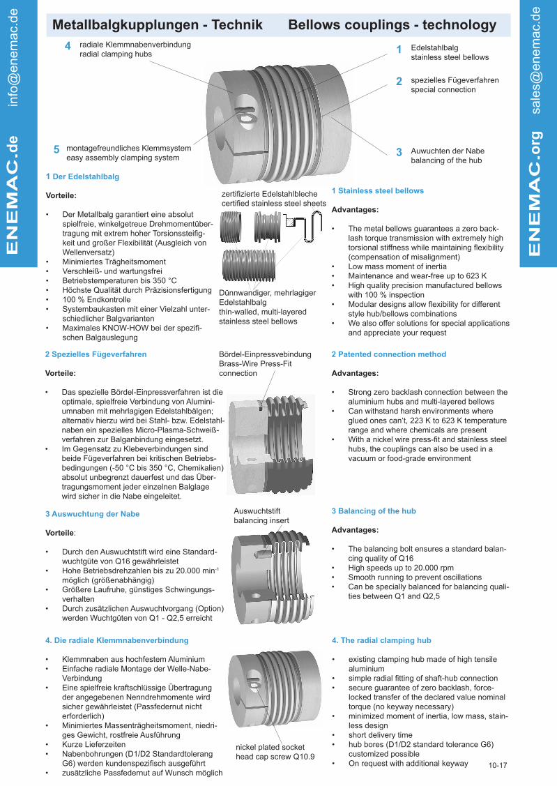
radiale Klemmnabenverbindungradial clamping hubs
4
montagefreundliches Klemmsystemeasy assembly clamping system
5
Edelstahlbalgstainless steel bellows
1
2 spezielles Fügeverfahrenspecial connection
3 Auwuchten der Nabebalancing of the hub
1 Der Edelstahlbalg
Vorteile:
• Der Metallbalg garantiert eine absolut spielfreie, winkelgetreue Drehmomentüber-tragung mit extrem hoher Torsionssteifig-keit und großer Flexibilität (Ausgleich von Wellenversatz)
• Minimiertes Trägheitsmoment• Verschleiß- und wartungsfrei• Betriebstemperaturen bis 350 °C• Höchste Qualität durch Präzisionsfertigung• 100 % Endkontrolle• Systembaukasten mit einer Vielzahl unter-
schiedlicher Balgvarianten• Maximales KNOW-HOW bei der spezifi-
schen Balgauslegung
1 Stainless steel bellows
Advantages:
• The metal bellows guarantees a zero back-lash torque transmission with extremely high torsional stiffness while maintaining flexibility (compensation of misalignment)
• Low mass moment of inertia• Maintenance and wear-free up to 623 K• High quality precision manufactured bellows
with 100 % inspection• Modular designs allow flexibility for different
style hub/bellows combinations• We also offer solutions for special applications
and appreciate your request
Dünnwandiger, mehrlagiger Edelstahlbalgthin-walled, multi-layered stainless steel bellows
zertifizierte Edelstahlblechecertified stainless steel sheets
2 Spezielles Fügeverfahren
Vorteile:
• Das spezielle Bördel-Einpressverfahren ist die optimale, spielfreie Verbindung von Alumini-umnaben mit mehrlagigen Edelstahlbälgen; alternativ hierzu wird bei Stahl- bzw. Edelstahl-naben ein spezielles Micro-Plasma-Schweiß-verfahren zur Balganbindung eingesetzt.
• Im Gegensatz zu Klebeverbindungen sind beide Fügeverfahren bei kritischen Betriebs-bedingungen (-50 °C bis 350 °C, Chemikalien) absolut unbegrenzt dauerfest und das Über-tragungsmoment jeder einzelnen Balglage wird sicher in die Nabe eingeleitet.
2 Patented connection method
Advantages:
• Strong zero backlash connection between the aluminium hubs and multi-layered bellows
• Can withstand harsh environments where glued ones can‘t, 223 K to 623 K temperature range and where chemicals are present
• With a nickel wire press-fit and stainless steel hubs, the couplings can also be used in a vacuum or food-grade environment
3 Auswuchtung der Nabe
Vorteile:
• Durch den Auswuchtstift wird eine Standard-wuchtgüte von Q16 gewährleistet
• Hohe Betriebsdrehzahlen bis zu 20.000 min-1 möglich (größenabhängig)
• Größere Laufruhe, günstiges Schwingungs-verhalten
• Durch zusätzlichen Auswuchtvorgang (Option) werden Wuchtgüten von Q1 - Q2,5 erreicht
3 Balancing of the hub
Advantages:
• The balancing bolt ensures a standard balan-cing quality of Q16
• High speeds up to 20.000 rpm • Smooth running to prevent oscillations • Can be specially balanced for balancing quali-
ties between Q1 and Q2,5
Bördel-EinpressvebindungBrass-Wire Press-Fit connection
Auswuchtstiftbalancing insert
4. Die radiale Klemmnabenverbindung
• Klemmnaben aus hochfestem Aluminium• Einfache radiale Montage der Welle-Nabe-
Verbindung• Eine spielfreie kraftschlüssige Übertragung
der angegebenen Nenndrehmomente wird sicher gewährleistet (Passfedernut nicht erforderlich)
• Minimiertes Massenträgheitsmoment, niedri-ges Gewicht, rostfreie Ausführung
• Kurze Lieferzeiten• Nabenbohrungen (D1/D2 Standardtolerang
G6) werden kundenspezifisch ausgeführt• zusätzliche Passfedernut auf Wunsch möglich
4. The radial clamping hub
• existing clamping hub made of high tensile aluminium
• simple radial fitting of shaft-hub connection• secure guarantee of zero backlash, force-
locked transfer of the declared value nominal torque (no keyway necessary)
• minimized moment of inertia, low mass, stain-less design
• short delivery time• hub bores (D1/D2 standard tolerance G6)
customized possible• On request with additional keyway
nickel plated sockethead cap screw Q10.9

Metallbalgkupplungen - Technik Bellows couplings - technologyENEMAC.d
e in
fo@
enem
ac.
de
ENEMAC.o
rg
sale
s@enem
ac.
de
10-17
5. Montagefreundliches Klemmsystem
Vorteile:
• Die Revolution in der Kupplungsmontage • Keine Stauchung bzw. Längung des Balges• Erhebliche Zeitersparnis, keine Nacharbeit• Blindmontage möglich, Bohrung in der
Kupplungsglocke ist ausreichend• Toleranzfehler der Welle-Nabe-Passung
werden weitgehend kompensiert• Keine Zusatzwerkzeuge erforderlich• Keine Beschädigung der Nabenbohrung• Keine Zerstörung der Kupplung bei der
Demontage des Motors
5. Easy assembly clamping system
Advantages:
• Revolution of coupling fitting• no shortening or extension of bellows• grave time saving, no re-operation• blind assembly possible, hole in bell housing
is enough• widely compensation of tolerance demerit of
shaft-hub-fit• no additional tool necessary• no damage of hub bores and bellows at de-
mounting of motor
6 Die Konusklemmverbindung
Vorteile:
• Durch Kraftverstärkung (Keilprinzip) sichere Übertragung der Drehmomente auch bei kleinen Durchmessern
• Spielfrei, verschleißfrei, kraftschlüssig (keine Passfeder erforderlich)
• Rotationssysmmetrisch, sehr gute Wuchtgüte, für hohe Drehzahlen geeignet
• Konusspreiznabe für Axialmontage Hohlwelle
6. The conical connection
Advantages:
• through force amplifying (wedge principal) a safe trans-mission of the torque although for smaller bore sizes (hub additionally sliced) is guaranteed.
• zero backlash and maintenance-free, actuated by adhe-rence with our keyway
• rotary symmetric, good balancing• expanding cone hub for axial mounting in a hollow shaft
Die Kupplungsklemmnabe ist spielfrei und kraftschlüs-sig mit der Welle verbunden
The clamping hub is back-lash free and positively tied with the shaft.
Die Kupplungsklemmnabe wird für die Montage elastisch ausgeweitet
The clamping hub is expanded elastically for assembly
Konus-Klemmbuchse
conical clamping hub
Konus-Spannringnabe
conical ring hub
Konus-Spreiznabe
expanding cone hub

Metallbalgkupplung EWA Metal bellows coupling EWA
Technische Daten / technical data:
• 6-welliger Balg - montagefreundliche Klemmnabe
• kostengünstige Standardbaureihe
• 6-corrugation bellows - easy assembly clamping
hub
• cost-effectivestandardtype
Abmessungen nach / dimensions acc. to DIN ISO 2768 cH:
EN
EM
AC
.de info
@enem
ac.
de
EN
EM
AC
.org
sale
s@enem
ac.
de
20-17
EWA 20 35 60 80 170 270 400 600 900 1300 1800
Nennmoment nominal torque
[Nm] 20 35 60 80 170 270 400 600 900 1300 1800
Trägheitsmomentmoment of inertia
[10-3kgm2] 0,14 0,14 0,29 0,79 0,83 2,2 2,4 5,3 9 14 15
Torsionssteifetorsional stiffness [Nm/arcmin] 5,2 5,8 8,7 14 17 32 47 67 105 170 260
max. Drehzahlmax.speed
[min-1] 20.000 20.000 17.000 14.000 14.000 11.000 11.000 9.500 8.500 7.000 7.000
max. Wellenversatz axial ± [mm] 0,8 0,8 0,9 1 1 1 1 1 1 1 1
max. shaft displacement lateral [mm] 0,25 0,25 0,3 0,3 0,3 0,3 0,3 0,3 0,3 0,3 0,3
Federsteife axial[N/mm]
51 51 49 45 80 70 100 100 145 130 250
spring rate lateral 190 190 260 280 470 450 640 980 1000 920 1900
Masse ca.weight approx.
[kg] 0,3 0,3 0,5 0,8 0,8 1,4 1,5 2,4 3,3 4,2 4,5
Anziehmoment Schraubentightening torque of screws
[Nm] 14 1435
(30)65
(50)65
(50)115(90)
115(90)
180 (140)
180 (140)
290 (240)
290 (240)
Werkstoff:Balg: EdelstahlNaben: hochfestes Aluminium Schrauben: ISO 4762 vernickelt
EWA 20 35 60 80 170 270 400 600 900 1300 1800
Øa [mm] 56 56 66 82 82 101 101 122 133 157 157
c [mm] 19 19 22 28,5 28,5 35 35 42 47 54 54
f M6 M6 M8 M10 M10 M12 M12 M14 M14 M16 M16
g [mm] 30 30 33 38 40 42 48 52 53 55 55
h [mm] 8 8 9 11,5 11,5 13 13 16 18,5 20 20
L [mm] 70 70 77 90 92 100 106 120 143 145 145
L* [mm] 81 81 87 102 104 106 112 - - - -
Ø D1/2 min. [mm] 8 10 13 16 18 25 28 32 40 48 54
Ø D1/2 max. [mm] 32 3228
(35)32
(43)32
(43)42
(55)42
(55)55
(68)65
(75)70
(85)70
(85)
Temperaturbereich: -40 °C bis 200 °C
Kleinere Nennmomente von 2 Nm bis 12 Nm siehe Miniaturkupplung Typ EWA.
Reduziertes Anzugsmoment für größere Nabenbohrungen, s. auch D1/D2 (Klammerwerte).L*: variable Länge bei größeren Klemmnaben
temperature range: 233 K up to 473 K
For smaller torques from 2 Nm up to 12 Nm see miniature coupling EWA.
Reduced tightening torque for bigger hub bores. see D1/D2 (values in brackets).
L*: variable length for bigger clamping hub sizes
Bestellbeispiel / ordering example: EWA 170 - D1 = 30 H7 - D2 = 35 H7
material:
bellows: stainless steelhubs: high tensile aluminiumscrews: ISO 4762 nickel plated
f - ISO 4762
L

Metallbalgkupplung EWB Metal bellows coupling EWB
Technische Daten / technical data:
• 4-welliger Balg - kurze Baulänge
• hohe Torsionssteife
• montagefreundliche Klemmnabe
• 4-corrugation bellows - short design
• hightorsionalstiffness• easy assembly clamping system
Abmessungen nach / dimensions acc. to DIN ISO 2768 cH:
EN
EM
AC
.de info
@enem
ac.
de
EN
EM
AC
.org
sale
s@enem
ac.
de
20-17
EWB 25 35 60 100 170 270 400 600 900
Nennmoment nominal torque
[Nm] 25 35 60 100 170 270 400 600 900
Trägheitsmomentmoment of inertia
[10-3kgm2] 0,064 0,13 0,27 0,35 0,76 2 2,15 5 9,0
Torsionssteifetorsional stiffness [Nm/arcmin] 4 9 14 20 28 52 74 106 156
max. Drehzahlmax.speed
[min-1] 12.000 20.000 17.000 16.000 14.000 11.000 11.000 9.500 8.500
max. Wellenversatz axial ± [mm] 0,5 0,5 0,6 0,6 0,8 0,8 0,7 0,7 0,8
max. shaft displacement lateral [mm] 0,15 0,2 0,2 0,2 0,2 0,2 0,2 0,2 0,2
Federsteife axial
[N/mm]
36 70 70 110 98 90 135 140 210
spring rate lateral 180 450 650 1.200 1.000 1.300 1.500 2.800 3.050
Masse ca.weight approx.
[kg] 0,18 0,3 0,4 0,5 0,8 1,3 1,4 2,3 3,5
Anziehmoment d. Schraubentightening torque of screws
[Nm] 8 1435
(30)*35
(30)*65
(50)*115
(90)*115
(90)*180
(140)*180
(140)*
Werkstoff:Balg: EdelstahlNaben: hochfestes Aluminium Schrauben: ISO 4762 vernickelt
EWB 25 35 60 100 170 270 400 600 900
Øa [mm] 50 56 66 71 82 101 101 122 133
c [mm] 17 19 22 25 28,5 35 35 42 47
f M5 M6 M8 M8 M10 M12 M12 M14 M14
g [mm] 24 21 23 23 28 29 33 36 37
h [mm] 6 8 9 9 11,5 13 13 16 18,5
L [mm] 58 61 67 68 80 87 91 104 127
L* [mm] - 72 77 - 92 93 97 - -
Ø D1/2 min. [mm] 10 10 13 14 18 25 28 32 40
Ø D1/2 max. [mm] 28 32 30 (35) 32 (38) 32 (43) 42 (55) 42 (55) 55 (68) 65 (75)
Temperaturbereich: -40 °C bis 200 °C
Kleinere Nennmomente von 2 Nm bis 12 Nm siehe Miniaturkupplung Typ EWB.* Reduziertes Anzugsmoment für größere Nabenbohrungen, s. auch D1/D2 (Klammerwerte).L*: variable Länge bei größeren Klemmnaben
temperature range: 233 K up to 473 K
For smaller torques from 2 Nm up to 12 Nm see miniature coupling EWB.
*Reduced tightening torque for bigger hub bores. see D1/D2 (values in brackets).
L*: variable length for bigger clamping hub sizes
Bestellbeispiel / ordering example: EWB 170 - D1 = 43 H7 - D2 = 40 H7
material:
bellows: stainless steelhubs: high tensile aluminiumscrews: ISO 4762 nickel plated
f - ISO 4762
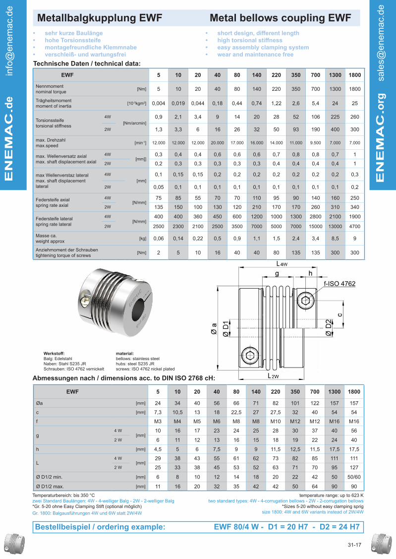
Metallbalgkupplung EWF Metal bellows coupling EWF
Technische Daten / technical data:
• sehr kurze Baulänge
• hohe Torsionssteife
• montagefreundliche Klemmnabe
• verschleiß- und wartungsfrei
• shortdesign,differentlength• hightorsionalstiffness• easy assembly clamping system
• wear and maintenance free
Abmessungen nach / dimensions acc. to DIN ISO 2768 cH:
EN
EM
AC
.de info
@enem
ac.
de
EN
EM
AC
.org
sale
s@enem
ac.
de
31-17
EWF 5 10 20 40 80 140 220 350 700 1300 1800
Nennmoment nominal torque
[Nm] 5 10 20 40 80 140 220 350 700 1300 1800
Trägheitsmomentmoment of inertia
[10-3kgm2] 0,004 0,019 0,044 0,18 0,44 0,74 1,22 2,6 5,4 24 25
Torsionssteifetorsional stiffness
4W
[Nm/arcmin]
0,9 2,1 3,4 9 14 20 28 52 106 225 260
2W 1,3 3,3 6 16 26 32 50 93 190 400 300
max. Drehzahlmax.speed
[min-1] 12.000 12.000 12.000 20.000 17.000 16.000 14.000 11.000 9.500 7.000 7.000
max. Wellenversatz axialmax. shaft displacement axial
4W[mm]]
0,3 0,4 0,4 0,6 0,6 0,6 0,7 0,8 0,8 0,7 1
2W 0,2 0,3 0,3 0,3 0,3 0,3 0,4 0,4 0,4 0,4 1
max Wellenverstaz lateralmax. shaft displacement lateral
4W
[mm]
0,1 0,15 0,15 0,2 0,2 0,2 0,2 0,2 0,2 0,2 0,3
2W 0,05 0,1 0,1 0,1 0,1 0,1 0,1 0,1 0,1 0,1 0,2
Federsteife axialspring rate axial
4W[N/mm]
75 85 55 70 70 110 95 90 140 160 250
2W 135 150 100 130 120 210 170 170 260 310 340
Federsteife lateralspring rate lateral
4W[N/mm]
400 400 360 450 600 1200 1000 1300 2800 2100 1900
2W 2500 2300 2100 2500 3500 7000 5000 7000 15000 13000 4700
Masse ca.weight approx
[kg] 0,06 0,14 0,22 0,5 0,9 1,1 1,5 2,4 3,4 8,5 9
Anziehmoment der Schraubentightening torque of screws
[Nm] 2 5 10 16 40 40 80 135 135 300 300
Werkstoff:Balg: EdelstahlNaben: Stahl S235 JRSchrauben: ISO 4762 vernickelt
EWF 5 10 20 40 80 140 220 350 700 1300 1800
Øa [mm] 24 34 40 56 66 71 82 101 122 157 157
c [mm] 7,3 10,5 13 18 22,5 27 27,5 32 40 54 54
f M3 M4 M5 M6 M8 M8 M10 M12 M12 M16 M16
g4 W
[mm]10 16 17 23 24 25 28 30 37 40 56
2 W 6 11 12 13 16 15 18 19 22 24 40
h [mm] 4,5 5 6 7,5 9 9 11,5 12,5 11,5 17,5 17,5
L 4 W
[mm]29 38 43 55 61 62 73 82 85 111 111
2 W 25 33 38 45 53 52 63 71 70 95 127
Ø D1/2 min. [mm] 6 8 10 12 14 18 20 22 42 50 50/60
Ø D1/2 max. [mm] 11 16 20 32 35 42 42 50 64 90 90
Temperaturbereich: bis 350 °Czwei Standard Baulängen: 4W - 4-welliger Balg - 2W - 2-welliger Balg*Gr. 5-20 ohne Easy Clamping Stift (optional möglich)
Gr. 1800: Balgausführungen 4W und 6W statt 2W/4W
temperature range: up to 623 Ktwo standard types: 4W - 4-corrugation bellows - 2W - 2-corrugation bellows
*Sizes 5-20 without easy clamping sprigsize 1800: 4W and 6W variants instead of 2W/4W
Bestellbeispiel / ordering example: EWF 80/4 W - D1 = 20 H7 - D2 = 24 H7
material:
bellows: stainless steelhubs: steel S235 JRscrews: ISO 4762 nickel plated
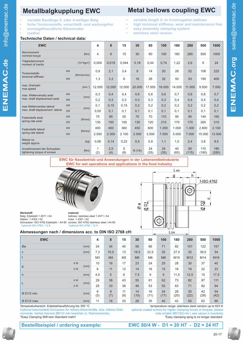
Metallbalgkupplung EWC Metal bellows coupling EWC
Technische Daten / technical data:
• variable Baulänge 2- oder 4-welliger Balg
• hohe Torsionssteife, verschleiß- und wartungsfrei
• montagefreundliche Klemmnabe
• rostfrei
• variable length 2- or 4-corrugation bellows
• hightorsionalstiffness,wearandmaintenancefree• easy assembly clamping system
• stainless steel version
Abmessungen nach / dimensions acc. to DIN ISO 2768 cH:
EN
EM
AC
.de info
@enem
ac.
de
EN
EM
AC
.org
sale
s@enem
ac.
de
20-17
EWC 4 8 15 30 60 100 180 280 500 1000
Nennmoment nominal torque
[Nm] 4 8 15 30 60 100 180 280 500 1000
Trägheitsmomentmoment of inertia
[10-3kgm2] 0,004 0,019 0,044 0,18 0,44 0,74 1,22 2,6 6 24
Torsionssteifetorsional stiffness
4W
[Nm/arcmin]
0,9 2,1 3,4 9 14 20 28 52 106 225
2W 1,3 3,3 6 16 26 32 50 93 190 400
max. Drehzahlmax.speed
[min-1] 12.000 12.000 12.000 20.000 17.000 16.000 14.000 11.000 9.500 7.000
max. Wellenversatz axialmax. shaft displacement axial
4W[mm]
0,3 0,4 0,4 0,6 0,6 0,6 0,7 0,8 0,8 0,7
2W 0,2 0,3 0,3 0,3 0,3 0,3 0,4 0,4 0,4 0,4
max Wellenverstaz lateralmax. shaft displacement lateral
4W[mm]
0,1 0,15 0,15 0,2 0,2 0,2 0,2 0,2 0,2 0,2
2W 0,05 0,1 0,1 0,1 0,1 0,1 0,1 0,1 0,1 0,1
Federsteife axialspring rate axial
4W[N/mm]
75 85 55 70 70 110 95 90 140 160
2W 135 150 100 130 120 210 170 170 260 310
Federsteife lateralspring rate lateral
4W[N/mm]
400 400 360 450 600 1.200 1.000 1.300 2.800 2.100
2W 2.500 2.300 2.100 2.500 3.500 7.000 5.000 7.000 15.000 13.000
Masse ca.weight approx
[kg] 0,06 0,14 0,22 0,5 0,9 1,1 1,5 2,4 3,8 8,5
Anziehmoment der Schraubentightening torque of screws
[Nm]1
(2)2,5 (4)
5 (8)
9 (14)24
(35)24
(35)45
(65)80
(115)110
(180)180
(280)
Werkstoff:Balg: Edelstahl 1.4571 / A4Naben: 1.4302 / A2Schrauben: ISO 4762 Edelstahl / A4-80 *optional ISO 4762 / 12.9
EWC 4 8 15 30 60 100 180 280 500 1000
Øa [mm] 24 34 40 56 66 71 82 101 122 157
c [mm] 7,3 10,5 13 18,5 22,5 25 27,5 32 39,5 54
f M3 M4 M5 M6 M8 M8 M10 M12 M14 M16
g4 W
[mm]10 16 17 23 24 25 28 30 37 40
2 W 6 11 12 14 16 15 18 19 22 23
h [mm] 4,5 5 6 7,5 9 9 11,5 12,5 15 17,5
L 4 W
[mm]29 38 43 55 61 62 73 82 97 111
2 W 25 33 38 46 53 52 63 71 82 94
Ø D1/2 min. [mm]8
(5)9
(7)11 (8)
14 (10)
16 (11)
24 (17)
28 (20)
30 (22)
42 (28)
54 (42)
Ø D1/2 max. [mm] 11 16 20 28 35 40 42 50 62 90
Temperaturbereich: Edelstahlausführung bis 350 °COptional beschichtete Schrauben für höhere Klemmkräfte, bzw. höhere Dreh-momente, hierbei kleinere ØD1/2 min beachten (s. Klammerwerte).*Easy Clamping Stift kein Standard mehr!
temperature range: stainless steel version up to 623 Koptional coated screws for higher clamping forces or torques, please
note smaller ØD1/D2 min ( see values in brackets)*Easy clamping sprig is no longer standard.
Bestellbeispiel / ordering example: EWC 80/4 W - D1 = 20 H7 - D2 = 24 H7
material:
bellows: stainless steel 1.4571 / A4hubs: 1.4301 / A2screws: ISO 4762 stainless steel / A4-80*optional ISO 4762 / 12.9
EWC für Nassbetrieb und Anwendungen in der Lebensmittelindustrie
EWC for wet operations and applications in the food industry

Metallbalgkupplung EWG Metal bellows coupling EWG
Technische Daten / technical data:
• 4-welliger Balg - kurze Baulänge
• montagefreundliche Klemmnabe
• Spreizkonusnabe für integrierten Anbau
• interner Axialanschlag
• 4-corrugation bellows - short design
• easy assembly clamping systems
• for direct mounting in hollow shafts
• internal axial stop
Abmessungen nach / dimensions acc. to DIN ISO 2768 cH:
EN
EM
AC
.de info
@enem
ac.
de
EN
EM
AC
.org
sale
s@enem
ac.
de
20-17
EWG 2 8 20 60 170 400 600
Nennmoment nominal torque
[Nm] 2 8 20 60 170 400 600
Trägheitsmomentmoment of inertia
[10-3kgm2] 0,01 0,02 0,13 0,28 0,94 1,95 4,2
Torsionssteifetorsional stiffness [Nm/arcmin] 0,4 1,9 7 13 27 64 107
max. Drehzahlmax.speed
[min-1] 12.000 12.000 20.000 17.000 14.000 11.000 9.500
max. Wellenversatz axial ± [mm] 0,25 0,5 0,5 0,6 0,8 0,7 0,7
max. shaft displacement lateral [mm] 0,1 0,15 0,2 0,2 0,2 0,2 0,2
Federsteife axial[N/mm]
32 20 70 70 100 135 145
spring rate lateral 100 90 480 650 1000 1500 3000
Masse ca.weight approx.
[kg] 0,03 0,1 0,3 0,4 0,8 1,4 2,7
Anziehmoment d. Schraubentightening torque of screws
f / i [Nm] 2 (2)* 8 (8)* 14 (14)*35 (30)*
/ 35 65 (50)*
/ 65115 (90)*
/ 115180 (140)*
/ 115
Werkstoff:Balg: EdelstahlNaben: hochfestes Aluminium Spreizkonus: VergütungsstahlSchrauben: ISO 4762 vernickelt
EWG 2 8 20 60 170 400 600
Øa [mm] 24,5 (27,5) 40 (44,5) 56 66 82 101 122
Øb [mm] 22 35 51 61 77 95 110
c [mm] 7,5 13 19 22 28,5 35 42
e [mm] 10 20 23 23 30 32 42
f/i M3 M5 M6 M8 M10 M12 M14/M12
h [mm] 4,5 6 8 9 11,5 13 16
L [mm] 38 61 71 75 92 102 120
t min[mm]
11 15,5 19 21 25 28 31
t max 20 (14) 33 38 40 48 56 63
Ø D1 min.[mm]
3 6 8 13 18 28 32
Ø D1 max. 10 (14) 19 (21) 32 28 (35) 32 (43) 42 (55) 55 (68)
Ø D2 min.[mm]
8 13 15 20 24 30 35
Ø D2 max. 12 18 20 28 32 38 48
Temperaturbereich: -40 °C bis 200 °C
Hinweis: Die entsprechenden Wellenbohrungen für den Spreizkonus ØD2 mit Fertigungstoleranz H7. Größen EWG 2 und 8 ohne montage-freundliche Klemmnabe.(Klammerwerte): Reduziertes Anzugsmoment für größere Bohrungs-durchmesser, s. ØD1/ØD2
temperature range: 233 K up to 473 K
Notice: the associated boresize for the expanding cone ØD2 with tolerance H7. Sizes EWG 2 and 8 without easy assembly
clamping system(values in brackets): reduced tightening torque for bigger bore sizes,
s ØD1/ØD2
Bestellbeispiel / ordering example: EWG 20 - D1 = 15 H7 - D2 = 20 g6
material:
bellows: stainless steelhubs: high tensile aluminiumexpanding cone: tempered steelscrews: ISO 4762 nickel plated
4762
i - ISO 4762
f - ISO 4762

Metallbalgkupplung EWH Metal bellows coupling EWH
Technische Daten / technical data:
• 6-welliger Balg - kurze Baulänge• beidseitige Konus-Klemmnaben• kostengünstige Standardbaureihe
• 6-corrugation bellows - short design• conical hub on both sides• cost-effective standard types
Abmessungen nach / dimensions acc. to DIN ISO 2768 cH:
ENEMAC.d
e in
fo@
enem
ac.
de
ENEMAC.o
rg
sale
s@enem
ac.
de
10-17
EWH 10 20 35 60 80 170 270 400 600 900 1300 2500 4000
Nennmoment nominal torque
[Nm] 10 20 35 60 80 170 270 400 600 900 1300 2500 4000
Trägheitsmomentmoment of inertia
[10-3kgm2] 0,03 0,1 0,1 0,3 0,9 0,9 2,5 2,8 5,5 10 20 103 110
Torsionssteifetorsional stiffness
[Nm/arcmin] 2,1 5,5 6 9 14 18 32 47 67 105 170 450 700
max. Drehzahlmax.speed
[min-1] 20.000 20.000 20.000 20.000 16.000 16.000 13.000 13.000 11.000 10.000 8.500 6.500 6.500
max. Wellenversatz axial ± [mm] 0,6 0,8 0,8 0,9 1 1 1 1 1 1 1 1 3
max. shaft displacement lateral [mm] 0,15 0,25 0,25 0,3 0,3 0,3 0,3 0,3 0,3 0,3 0,3 0,3 1,2
Federsteife axial[N/mm]
20 51 51 49 48 80 70 100 100 145 130 170 480
spring rate lateral 93 190 190 260 220 400 450 640 980 1000 920 1350 5000
Masse ca.weight approx.
[kg] 0,22 0,4 0,4 0,8 1,3 1,3 2,4 2,5 3,6 5,5 7,7 22 33
Anziehmoment d. Schraubentightening torque of screws
[Nm] 3 3 3 10 10 10 25 25 50 50 90 210 210
Werkstoff:Balg: EdelstahlNaben: VergütungsstahlSchrauben: ISO 4017 vernickelt
EWH 10 20 35 60 80 170 270 400 600 900 1300 2500 4000
Øa [mm] 40 56 56 66 82 82 101 101 122 132 157 203 203
Øb [mm] 34 52 52 62 78 78 96 96 112 127 140 194 173
Øc [mm] 27 30 30 36 50 50 62 62 70 83 98 144 144
e [mm] 45 48 48 53 58 60 68 74 78 94 96 147 223
6 x f M4 M4 M4 M6 M6 M6 M8 M8 M10 M10 M12 M16 M16
g [mm] 7 12 12 5 4 6 2 8 6 6 6 8 84
h [mm] 33 44 44 47 52 54 58 64 68 76 78 97 174
L [mm] 51 54 54 61 66 68 79 85 91 107 111 167 243
Ø D1/2 min.[mm]
6 10 10 12 18 20 28 30 35 40 40 50 60
Ø D1/2 max. 16 19 19 24 35 35 42 42 50 60 75 102 102
vorgebohrtprebored
[mm] 5 8 8 11 17 17 25 25 28 34 38 49 49
Temperaturbereich: -40 °C bis 300 °CHinweis: Baugröße 4000 mit 4-welligem Balg und Schrumpfscheiben (bis max. D= Ø130 mm)Höhere Drehmomente auf Anfrage möglich.
temperature range: 233 K up to 573 KNote: size 4000 with 4-corrugation bellows and shrink disc
(max up to D = Ø130 mm) Higher torques possible on request.
Bestellbeispiel / Ordering example: EWH 270 - D1 = 42 H7 - D2 = 30 H7
material:bellows: stainless steelhubs: tempered steelscrews: ISO 4017 nickel plated

Metallbalgkupplung EWHL Metal bellows coupling EWHL
Technische Daten / technical data:
• gerader Balg
• beidseitige Konus-Klemmnaben
• geringe Rückstellkräfte
• hohe Torsionssteife
• straight bellows
• conical hub on both sides
• low restoring forces
• high torsional rigidity
Abmessungen nach / dimensions acc. to DIN ISO 2768 cH:
EN
EM
AC
.de info
@enem
ac.
de
EN
EM
AC
.org
sale
s@enem
ac.
de
20-17
EWHL 25 50 65 100 200 300 450 540 850 1500 2500
Nennmoment nominal torque
[Nm] 25 50 65 100 200 300 450 540 850 1500 2500
Trägheitsmomentmoment of inertia
[10-3kgm2] 0,1 0,1 0,3 0,75 0,84 2,3 2,4 4,8 18 19 100
Torsionssteifetorsional stiffness [Nm/arcmin] 10 11 13 24 30 53 80 100 160 290 700
max. Drehzahlmax.speed
[min-1] 25.000 25.000 23.000 18.500 18.500 15.000 15.000 12.500 10.000 10.000 7.500
max. Wellenversatz axial ± [mm]] 0,3 0,3 0,3 0,5 0,3 0,4 0,4 0,5 0,7 0,6 0,4
max. shaft displacement lateral [mm] 0,2 0,2 0,3 0,4 0,3 0,3 0,3 0,5 0,6 0,5 0,5
Federsteife axial[N/mm]
150 160 90 100 220 210 300 300 200 520 550
spring rate lateral 150 170 80 95 120 160 260 360 170 490 590
Masse ca.weight approx.
[kg] 0,4 0,4 0,7 1,2 1,25 2,2 2,3 3,4 7,5 7,7 23
Anziehmoment d. Schraubentightening torque of screws
[Nm] 3 3 10 10 10 25 25 50 90 90 210
Werkstoff:Balg: EdelstahlNaben: VergütungsstahlSchrauben: ISO 4017 vernickelt
EWHL 25 50 65 100 200 300 450 540 850 1500 2500
Øa [mm] 56 56 66 82 82 101 101 122 157 157 203
Øb [mm] 52 52 62 78 78 96 96 112 140 140 194
Øc [mm] 30 30 36 50 50 62 62 70 98 98 138
e [mm] 51 51 61 70 76 89 89 98 137 137 211
6 x f M4 M4 M6 M6 M6 M8 M8 M10 M12 M12 M16
g [mm] 15 15 13 16 22 25 25 26 44 44 72
h [mm] 47 47 55 64 70 81 81 88 119 119 161
L [mm] 57 57 69 78 84 101 101 111 152 152 231
Ø D1/2 min.[mm]
10 12 12 18 22 28 28 35 40 42 50
Ø D1/2 max. 19 19 24 35 35 42 42 48 70 70 102
vorgebohrtprebored
[mm] 8 8 11 17 17 25 25 28 38 38 49
Temperaturbereich: -40°C bis 300°C
Hinweis: höhere Drehmomente auf Anfrage möglich
temperature range 233 K up to 573 K
Note: higher torques possible on request
Bestellbeispiel / ordering example: EWHL 450 - D1 = 28 H7 - D2 = 35 H7
material:
bellows: stainless steelhubs: tempered steelscrews: ISO 4017 nickel plated
f - ISO 4017

Metallbalgkupplung EWI Metal bellows coupling EWI
Technische Daten / technical data:
• montagefreundliche Klemmnaben
• Halbschalenausführung
• spielfrei,verdrehsteif,flexibel,verschleiß-und wartungsfrei
• easy installation due to splitted hub design
• zerobacklash,torsionalstiff,customizedlength,wearlessandmaintenance-free
Abmessungen nach / dimensions acc. to DIN ISO 2768 cH:
EN
EM
AC
.de info
@enem
ac.
de
EN
EM
AC
.org
sale
s@enem
ac.
de
31-17
EWI 20 40 80 140 220 350 700 1800
Nennmoment nominal torque
[Nm] 20 40 80 140 220 350 700 1800
Trägheitsmomentmoment of inertia
[10-3kgm2] 0,045 0,2 0,5 0,8 1,4 3,0 7,3 46
Torsionssteifetorsional stiffness [Nm/arcmin] 3,4 (6) 9 (16) 14 (26) 20 (32) 28 (50) 52 (93) 106 (190) 300 (--)
max. Drehzahlmax.speed
[min-1] 20.000 17.000 14.000 11.000 10.000 9.500 8.000 6.000
max. Wellenversatz axial ± [mm] 0,5 (0,3) 0,6 (0,3) 0,6 (0,3) 0,6 (0,3) 0,7 (0,4) 0,8 (0,4) 0,8 (0,4) 1 (--)
max. shaft displacement lateral [mm] 0,15 (0,1) 0,2 (0,1) 0,2 (0,1) 0,2 (0,1) 0,2 (0,1) 0,2 (0,1) 0,2 (0,1) 0,2 (--)
Federsteife axial
[N/mm]
55 (100) 70 (130) 70 (120) 110 (210) 95 (170) 90 (170) 140 (260) 340 (--)
spring rate lateral360
(2100)450
(2500)600
(3500)1200
(7000)1000
(5000)1300
(7000)2800
(15000)4700 (--)
Masse ca.weight approx.
[kg] 0,25 0,6 0,9 1,25 1,8 2,8 4,6 15
Anziehmoment der Schraubentigthening torque of screws
[Nm] 10 16 40 40 80 135 200 300
Werkstoff:Balg: EdelstahlNaben: S235 JRSchrauben: ISO 4762 vernickelt
EWI 20 40 80 140 220 350 700 1800
Øa [mm] 40 56 66 71 82 101 122 157
Øb [mm] 38 51 62 71 76 89 108 145
c [mm] 25,5 36 45 54 55 64 78 108
f M5 M6 M8 M8 M10 M12 M14 2 x M16
g [mm] 22 (17) 32 (22) 32 (24) 33 (23) 37 (27) 40 (29) 47 (31) 55 (--)
h [mm] 6 7,5 8 8,5 11 13 15 18 (30)
L [mm] 50 (45) 66 (56) 68 (60) 71 (61) 85 (75) 94 (83) 107 (91) 190 (--)
t [mm] 12 15 16 17 22 24 27 64
Ø D1/2 min.[mm]
8 12 14 14 20 22 35 35
Ø D1/2 max. 19 28 35 42 42 48 62 85
Temperaturbereich: -40 °C - +350 °C
Balg-Nabe-Verbindung durch Mikro-Plasma Schweißverfahren.Standardausführung mit 4-welligem Balg 4W, alternativ mit 2-welligem Balg (2W), s. Klammerwerte.
Der Abstand zwischen Antriebs- und Abtriebswelle MUSS GRÖSSER sein als das Maß „g“.
temperature range: 233 K up to 623 K
Bellows-Hub-Connection through micro-plasma welding process.Standard version with 4-corrugation bellows 4W, alternatively with
2-corrugation bellows (2W), see figures in bracket.
The distance between driving shaft and pinion MUST BE LARGER than „g“.
Bestellbeispiel/orderingexample:EWI220/4W-D1=24H7-D2=30H7
material:
bellows: stainless steelhubs: S235 JRscrews: ISO 4762 nickel plated
f - ISO 4762

h
ØD
2
c
Øa
L
Øb
f - DIN 912g
V
ØD
1
Metallbalgkupplung EWM Metal bellows coupling EWM
Technische Daten / technical data:
• steckbare Ausführung, Blindmontage möglich
• minimierter Montageaufwand - hohe Torsionssteife
• spielfreie, exakte Drehmomentübertragung
• plug-in-design, blind assembly possible
• hightorsionalstiffness• zero backlash, exact torque transmission
Abmessungen nach / dimensions acc. to DIN ISO 2768 cH:
EN
EM
AC
.de info
@enem
ac.
de
EN
EM
AC
.org
sale
s@enem
ac.
de
20-17
EWM 10 20 35 60 100 170 270 400 600
Nennmoment nominal torque
[Nm] 10 20 35 60 100 170 270 400 600
Trägheitsmomentmoment of inertia
[10-3kgm2] 0,033 0,17 0,17 0,34 0,46 0,9 2,2 2,4 5,8
Torsionssteifetorsional stiffness [Nm/arcmin] 2 4,6 5 8 12 19 31 45 67
max. Drehzahlmax.speed
[min-1] 12.000 20.000 20.000 17.000 16.000 14.000 11.000 11.000 9.500
max. Wellenversatz axial ± [mm]] 0,6 0,5 0,5 0,6 0,6 0,8 0,8 0,7 0,7
max. shaft displacement lateral [mm] 0,15 0,2 0,2 0,2 0,2 0,2 0,2 0,2 0,2
Federsteife axial[N/mm]
20 70 70 70 120 100 95 135 145
spring rate lateral 93 480 480 650 1200 1000 1350 1500 3000
Masse ca.weight approx.
[kg] 0,15 0,38 0,38 0,6 0,66 0,95 1,6 1,7 2,7
Anziehmoment der Schraubentigthening torque of screws
[Nm] 8 14 1435
(30)*35
(30)*65
(50)*115
(90)*115
(90)*180
(140)*
axiale Vorspannkraftaxial preload force
[N] 30 110 110 110 180 150 140 200 220
Werkstoff:Balg: EdelstahlNaben: hochfestes AluminiumSchrauben: ISO 4762 vernickelt
EWM 10 20 35 60 100 170 270 400 600
Øa [mm] 40 56 56 66 71 82 101 101 122
Øb [mm] 43 61 61 71 75 87 106 106 126
c1/c2 [mm] 13/13 19/19 19/19 22/22 25/25 28,5/28,5 35/35 35/35 43,5/42
f M5 M6 M6 M8 M8 M10 M12 M12 M14
g [mm] 18 21 21 23 23,5 28 29 33 36
h1/h2 [mm] 6/6 8/8 8/8 8,5/9 8,5/9 11/11,5 12/15 12/13 13,5/16
V [mm] 1 - 1,5 1 - 1,5 1 - 1,5 1 - 1,5 1 - 1,5 1 - 1,5 1 - 1,5 1 - 1,5 1 - 1,5
L** [mm] 62 77,5 77,5 85,5 86 99,5 106,5 110,5 122,5
Ø D1/2 min.
[mm]
6 8 10 13 14 18 25 28 32
Ø D1/2 max. 20/19 30/32 30/3228
(34/35)34
(38/38)35
(43/43)45
(55/55)45
(55/55)55
(70/68)
Temperaturbereich: -40 °C - +200 °C
**Lieferlänge (± 1 mm) - ohne Vorspannung, s. Funktion EWMBaugröße EWM 1300 mit Konus-Klemmnabe auf Anfrage.*Reduziertes Anzugsmoment bei größeren Nabenbohrungen D1/D2
temperature range: 233 K up to 473 K
**delivery length (± 1 mm) - without preload - see function EWMSize EWM 1300 with conical clamping hub on request.*reduced tightening torque for bigger hub bores D1/D2
Bestellbeispiel / ordering example: EWM 170 - D1 = 28 G7 D2 = 35 G7
material:
bellows: stainless steelhubs: high-tensile aluminiumscrews: ISO 4762 nickel plated
f - ISO 4762
Vorspannung / preload

Metallbalgkupplung EWM Metal bellows coupling EWMENEMAC.d
e in
fo@
enem
ac.
de
ENEMAC.o
rg
sale
s@enem
ac.
de
Allgemein:
Steckbare, zweiteilige Metallbalgkupplungen der Baureihe EWM wurden für schwer zugängliche Anwendungsfälle konzipiert, bei denen keine Montagebohrung für die Klemmschrauben der Kupplungsnaben möglich oder generell eine Blindmontage erforderlich ist. Durch die axiale Steckbarkeit wird bei solchen Applikationen der Montageaufwand wesentlich reduziert. Auch im Servicefall vereinfacht sich die Demontage erheblich, da die Antriebseinheit ohne aufwendiges Lösen der Naben „nach hinten“ abgezogen werden kann. Die produktspezifischen Leis-tungsmerkmale der Metallbalg-Servokupplungen, wie absolute Spielfreiheit, hohe Torsionssteife, niedriges Massenträgheitsmo-ment, Ausgleich von Fluchtungsfehlern, sowie hohe Betriebs-drehzahlen und -temperaturen gelten ohne Abstriche auch für die steckbaren EWM-Kupplungen. Abhängig von den jeweiligen Betriebsparametern können steckbare Elastomerkupplungen vom Typ EWD und EWE eventuell eine Alternative darstellen.
General:
The pluggable, two-parted metal bellows couplings are constructed for applications which are difficult to reach, applications without assembly bore for the clamping screws of the coupling hubs or where generally only blindfitting is possible. For such applications, the assembly is facili-ated by the axial pluggability. Also, in case of service, the disassembly is much easier, because the drive unit can be torn off ‚backwards‘ without difficult loosening of the hubs. Product specific characteristics, which define the metal bel-lows couplings, nevertheless apply for the EWM couplings, too. These are the absolute zero backlash, high torsional stiffness, low mass moment of inertia, compensation of misalignments as well as high operating speed and high operation temperatures. Depending on the special opera-tion parameters, plug-in jaw couplings of series EWD and EWE provide a very good alternative.
Funktion:
Die axiale Steckbarkeit wird durch eine spielfreie Nase-Nut-Verbindung in Ganzmetallausfüh-rung (aluminiumoxiert) erreicht. Hierzu wird ein Nabenteil mit einer konischen Mitnehmernase, das Gegenstück mit einer kongruen-ten, konischen Nut ausgeführt. Ein zusätzlicher Zentrierbund garantiert die exakte Fluchtung der beiden Nabenhälften. Für die erforderliche, axiale Vorspannung der Steckver-bindung wird die Federwirkung des Metallbalges genutzt. Hierzu wird der Balg bei der Montage um ca. 1 -1,5 mm gedrückt. Dies bedeutet, dass sich die entspannte Kupplungslänge „L“ (siehe Maßtabelle) im montierten Zustand um das Vorspannmaß „V“ reduziert. Aufgrund dieser geringen Vorspannung wird die Funk-tionsfähigkeit des Metallbalges nicht beeinträchtigt. Auch auf die Wellenlagerung haben die resultierenden Rückstellkräfte in der Regel keine negative Auswirkung.
Function:
The axial pluggability is achieved by a zero backlash carrier keyway connec-tion in whole metal version (aluminium-anodized). For this, one hub part is delivered as a conical carrier, the counterpart with a congruent, conical keyway. An additional centering element guarantees an exact alignment of both hub halves. To achieve the necessary axial prestress of the plug-in-connec-tion, the spring tension of the metal bellows is used. For this, the bellows is
pressed during assembly by 1 to 1.5 mm. This means, that the unstressed coupling lenth ‚L‘ (see measuring table) is reduced by the prestress value ‚V‘ after assembly. Because of the low prestress, the operativeness of the metal bellows is not reduced. The resulting residual forces usually have no negative influence on the shaft bearing.
Montagehinweise:
Um die einwandfreie Funktionsfähig-keit der Steckverbindung zu gewähr-leisten, muss das Vorspannmaß des Metallbalges von 1 bis 1,5 mm unbedingt beachtet werden. In den meisten Fällen wird es ausreichend sein, wenn dies der Konstrukteur durch entsprechende Abmessungs-toleranzen der Kupplungsglocke be-rücksichtigt. Eine weitere Möglichkeit für den Monteur besteht darin, vor dem Motoranbau zuerst die komplet-te Kupplung auf der Abtriebswelle zu montieren (s. Skizze). Mit einer Tiefenlehre kann dann das Abstandsmaß „T“ von der An-lagefläche der Glocke bis zu Stirnfläche der Stecknabe ermittelt werden. Das Montagemaß „M“ auf der Motorwelle ergibt sich, indem zum Tiefenmaß „T“ das Vorspannmaß „V“ hinzu addiert wird. Bei Serienanwendungen kann die Montage der Motorwel-len-Nabe durch Verwendung eines entsprechenden Passringes erheblich vereinfacht werden. Falls bei dem Steckmontagevor-gang die Winkellage von Nase und Nut nicht übereinstimmt, wird der Metallbalg zusätzlich um einige Millimeter gestaucht (für Ausnahmefälle zulässige Balgdeformation). Durch langsa-mes Verdrehen der Antriebswelle rückt die Nase bei Synchron-stellung in die Nut ein und die Kupplung ist funktionsbereit.
Assembly notes:
To guarantee optimum perfor-mance of the plug-in-connec-tion, the prestress value of 1 to 1.5 mm at the metal bellows must definitely be given special care. In most cases, it is suffici-ent, when the designer consi-ders this. Another possibility for the mechanic is, to mount the whole coupling onto the drive shaft before fitting it to the mo-tor (see drawing). With a depth
gage the distance value ‚T‘ from the bearing surface of the bell to the front-part of the plug-in hub can be defined. The mounting value ‚M‘ on the engine shaft is given by adding the distance value ‚T‘ to the prestress value ‚V‘. In serial use the mounting can be faciltated to a great extent by using a corresponding adjusting ring. If the angular position of the carrier to the keyway does not fit during the plug-in, the metal bellows may be pressed for some more milimeters (this bellows deformation is allowed in exceptional cases). By slow turning of the drive shaft, the carrier fits the keyway in synchronous position and the coupling is ready for use.
Passring
adjusting ring
Motor
motor
M = T + V
10-17

Metallbalgkupplung EWP Metal bellows coupling EWP
Technische Daten / technical data:
• beidseitig mit Flanschnaben für variablen Anbau• drei Standard Baulängen, radiale Montage• kundenspezifische Anbauflansche
• flange hubs on both sides for variable mounting• three standard lengths, radial mounting• costumized mounting flange
Abmessungen nach / dimensions acc. to DIN ISO 2768 cH:
ENEMAC.d
e in
fo@
enem
ac.
de
ENEMAC.o
rg
sale
s@enem
ac.
de
10-17
EWP 50 65 100 200 300 450 540 900 1500 2500
Nennmoment nominal torque
[Nm] 50 65 100 200 300 450 540 900 1500 2500
Trägheitsmomentmoment of inertia
[10-3kgm2] 0,09 0,22 0,54 0,6 1,7 1,9 3,7 8,5 13,8 49
Torsionssteifetorsional stiffness
4W
[Nm/arcmin]
9 14 23 28 52 74 106 156 - -
6W 6 9 14 18 33 47 67 99 240 400
2x1W 9 11 22 34 45 66 96 - 295 605
max. Drehzahlmax.speed
4W/2x1W[min-1]
25.000 23.000 18.500 18.500 15.000 15.000 12.500 11.500 10.000 7.500
6W 20.000 20.000 16.000 16.000 13.000 13.000 11.000 10.000 8.500 6.500
Wellenversatzmax. lateralshaft displacement
4W
[mm]
0,2 0,2 0,2 0,2 0,2 0,2 0,2 0,2 - -
6W 0,25 0,3 0,3 0,3 0,3 0,3 0,3 0,3 0,3 0,3
2x1W 0,2 0,2 0,4 0,2 0,3 0,2 0,3 - 0,3 0,4
Federsteifelateralspring rate
4W
[N/mm]
480 650 280 1000 1350 1500 3000 3050 - -
6W 190 260 280 470 450 640 980 1000 1500 1300
2x1W 160 85 110 299 156 247 370 - 480 550
Federsteifeaxialspring rate
4W
[N/mm]
70 70 64 98 94 135 145 210 - -
6W 51 49 45 80 70 100 100 145 240 170
2x1W 165 90 125 350 212 305 300 - 520 550
Masse ca.mass approx.
[kg] 0,2 0,35 0,55 0,6 1,1 1,2 1,7 3,0 3,8 7,1
Anziehmoment Schraubentigthening torque screws
[Nm] 4 14 14 14 35 40 65 140 220 220
Werkstoff:Balg: EdelstahlNaben: Vergütungsstahl
EWP 50 65 100 200 300 450 540 900 1500 2500
Øa [mm] 56 66 82 82 101 101 122 132 157 203
Øb [mm] 52 62 78 78 96 96 111 127 140 194
Øc [mm] 32 38 53 53 65 65 80 88 110 150
Øe H7 [mm] 25 28 40 40 50 50 63 68 88 125
f [mm] 7 9 9 9 12 12 15 20 24 24
L
4W
[mm]
35 41 44 46 53 57 66 77 - -
6W 44 51 56 58 66 72 82 93 103 108
2x1W 47 59 68 74 89 89 102 - 144 172
6 x i M4 M6 M6 M6 M8 M8 M10 M14 M16 M16
Temperaturbereich: -40 °C - +300 °C
3 Standard Baulängen:4W - 4-welliger Balg; 6W - 6-welliger Balg; 2x1W - gerader Balg
temperature range: 233 K up to 573 K
3 standard types:4W - 4-corrugation bellows; 6W - 6-corrugation-bellows;
2x1W - straigth bellows
Bestellbeispiel: EWP 100 / 2x1W - Standardordering example: EWP 450 / 4W - ᴓe = 48 H7 / 8 M8 / ᴓc = 60 / L = 57
material:bellows: stainless steelhubs: tempered steel

Metallbalgkupplung EWS Metal bellows coupling EWS
Technische Daten / technical data:
• ‚High-Speed‘ - Version, Drehzahlen bis 30.000 min-1
• hohe Wuchtgüte, rotationssymmetrischer Aufbau
• niedriges Massenträgheitsmoment
• rostgeschützte Ausführung
• ‚high-speed‘ - version, speed up to 30.000 min-1
• high balance quality, symmetrical design
• low mass moment of inertia
• corrosion-resistant design
Abmessungen nach / dimensions acc. to DIN ISO 2768 cH:
EN
EM
AC
.de info
@enem
ac.
de
EN
EM
AC
.org
sale
s@enem
ac.
de
20-17
EWS 15 40 100 200 400 600
Nennmoment nominal torque
[Nm] 15 40 100 200 400 600
Trägheitsmomentmoment of inertia
[10-3kgm2] 0,03 0,13 0,37 0,86 2,5 5,3
Torsionssteifetorsional stiffness [Nm/arcmin] 2 9 20 28 70 100
max. Drehzahlmax. speed
[min-1] 30.000 30.000 27.000 23.000 19.000 15.000
max. Wellenversatzmax. shaft displacement
axial ±[mm]
0,5 0,5 0,6 0,7 0,7 0,7
lateral 0,1 0,1 0,1 0,1 0,1 0,1
Federsteifespring rate
axial[N/mm]
20 70 120 100 135 145
lateral 90 480 1200 1000 1500 3000
Masse ca.weight approx.
[kg] 0,15 0,30 0,55 0,83 1,6 2,5
Anziehmoment d. Schraubentightening torque of screws
[Nm] 3 4 8 12 30 45
Werkstoff:Balg: EdelstahlKonusring: hochfestes AluminiumKonusnabe: hochfestes AluminiumSchrauben: ISO 4762 vernickelt
EWS 15 40 100 200 400 600
Øa [mm] 40 56 71 82 101 122
Øb [mm] 38 53 66 78 98 113
Øc [mm] 27 40 52 62 78 91
e [mm] 61 67 77,5 89 106 125
6 x f M4 M4 M5 M6 M8 M10
g [mm] 18 21 23 28 33 36
h [mm] 32 35 39 46 55 62
L [mm] 67 71 80,5 94 112 130
Ø D1/2 min. [mm] 6 14 17 22 26 30
Ø D1/2 max. [mm] 15 22 32 40 50 60
vorgebohrtprebored
[mm] 5 8 12 15 18 22
Temperaturbereich: -40 °C - +200 °C
Als kraftschlüssige Welle-Nabe-Verbindung findet eine speziell konzi-pierte Konusspannringnabe Verwendung. Bei den vorgegeben Anzieh-momenten wird der Konusring kontrolliert gegen die Konusnabe auf „Block-Anschlag“ gezogen. Das anfängliche Spaltmaß reduziert sich auf Null. Somit ist ein Verkanten bzw. eine Überlastung des Konusrings ausgeschlossen.
temperature range: 233 K up to 473 K
As force-fit shaft-hub-connection a special conical clamping hub will be applicable. At specified tightening forces the conical ring
gets controlled pulled against the conical hub at ‚block-stop positi-on‘. The primary cleft width reduces to zero. So a twisting and an
overload of the conical ring is impossible.
Bestellbeispiel / ordering example EWS 100 - D1 = 28 H7 D2 = 40 H7
material:
bellows: stainless steelconical ring: high tensile aluminiumconical hub: high tensile aluminiumscrews: ISO 4762 nickel plated
f - ISO 4762

Metallbalgkupplung EWU Metal bellows coupling EWU
Technische Daten / technical data:
• gerader Balg, lange Baureihe
• montagefreundliches Klemmsystem
• geringe Rückstellkräfte
• hohe Torsionssteife
• straight bellows, long design
• easy assembly clamping system
• low restoring forces
• hightorsionalstiffness
Abmessungen nach / dimensions acc. to DIN ISO 2768 cH:
EN
EM
AC
.de info
@enem
ac.
de
EN
EM
AC
.org
sale
s@enem
ac.
de
20-17
EWU 25 50 65 100 200 300 450 550 1500
Nennmoment nominal torque
[Nm] 25 50 65 100 200 300 450 550 1500
Trägheitsmomentmoment of inertia
[10-3kgm2] 0,12 0,12 0,25 0,7 0,84 2 2,15 4,7 13
Torsionssteifetorsional stiffness [Nm/arcmin] 9 10 12 23 30 53 80 98 280
max. Drehzahlmax. speed
[min-1] 20.000 20.000 20.000 16.000 16.000 13.000 13.000 11.000 8.500
max. Wellenversatzmax. shaft displacement
axial ±[mm]
0,3 0,3 0,3 0,5 0,3 0,4 0,4 0,5 0,6
lateral 0,2 0,2 0,3 0,4 0,3 0,3 0,3 0,5 0,5
Federsteifespring rate
axial[N/mm]
150 160 90 100 220 210 300 300 520
lateral 150 170 80 95 120 160 260 360 490
Masse ca.weight approx.
[kg] 0,3 0,3 0,4 0,75 0,8 1,3 1,4 2,2 4,4
Anziehmoment Schraubentightening torque screws
[Nm] 14 1435
(30)*65
(50)*65
(50)*115
(90)*115
(90)*180
(140)*290
(240)*
Werkstoff:Balg: EdelstahlNaben: hochfestes AluminiumSchrauben: ISO 4762 vernickelt
EWU 25 50 65 100 200 300 450 550 1500
Øa [mm] 56 56 66 82 82 101 101 122 157
c [mm] 19 19 22 28,5 28,5 35 35 42 54
f M6 M6 M8 M10 M10 M12 M12 M14 M16
g [mm] 33 33 41 50 56 65 65 72 96
h [mm] 8 8 9 11,5 11,5 13 13 16 20
L [mm] 73 73 85 102 108 123 123 140 186
L** [mm] 84 84 95 114 120 129 129 - -
Ø D1/2 min. [mm] 8 10 13 16 18 28 35 32 48
Ø D1/2 max. [mm] 32 32 28 (35) 32 (43) 32 (43) 42 (45) 42 (45) 55 (68) 70 (85)
Temperaturbereich: -40 °C - +200 °C
*reduziertes Anzugsmoment für größere Nabenbohrungsdurchmesser, s. auch ØD1 / ØD2**alternative Baulänge mit größerer Klemmnabenbreite
temperature range: 233 K up to 473 K
*reduced tightening torque for bigger hub bore sizes - see also ØD1 / ØD2
**alternative length with bigger clamping hub width
Bestellbeispiel / ordering example EWU 100 D1 = 35 H7 D2 = 35 H7
material:
bellows: stainless steelhubs: high tensile aluminiumscrews: ISO 4762 nickel plated
OD
1
Oa
OD
2
c
g h
L
f - ISO 4762

ØD
1
Øa
ØD
2
t g h
L
c
KRH
KMH
f - ISO 4762
Metallbalgkupplungen EWPH/EWMH/EWRH Metal bellows couplings
Technische Daten / technical data:
• montagefreundliche Klemmnaben in Halbschalenausführung
• spielfrei,verdrehsteif,variableBaulängen,flexibel• verschleiß- und wartungsfrei, rostfreie Ausführung
• easy installation assembly in splitted hub design
• zerobacklash,torsionalstiff,flexible• stainless design, variable lengths
Abmessungen nach / dimensions acc. to DIN ISO 2768 cH:
EN
EM
AC
.de info
@enem
ac.
de
EN
EM
AC
.org
sale
s@enem
ac.
de
20-17
EWPH/EWMH/EWRH 10 40 80 200 400
Nennmoment nominal torque
[Nm] 10 40 80 200 400
Trägheitsmomentmoment of inertia
[10-3kgm2] 0,02 0,2 0,5 1,2 3
Torsionssteife
torsional stiffness
EWPH
[Nm/arcmin]
1,7 9 14 25 74
EWMH 1,1 5,8 8,7 17 47
EWRH - 10 12 30 80
max. Drehzahlmax. speed
[min-1] 20.000 16.000 12.000 10.000 8.000
max. Wellenversatz lateralmax. shaft displacement
EWPH
[mm]
0,15 0,2 0,2 0,2 0,2
EWMH 0,25 0,25 0,3 0,3 0,3
EWRH - 0,2 0,3 0,3 0,3
Federsteifeaxialspring rate
EWPH
[N/mm]
70 70 70 98 135
EWMH 45 51 49 80 100
EWRH - 170 95 120 260
Federsteifelateralspring rate
EWPH
[N/mm]
60 190 260 470 640
EWMH 224 450 650 1000 1500
EWRH - 170 80 120 260
Masse ca.weight approx.
[kg] 0,1 0,5 0,8 1,2 2
Anzugsmoment Schraubentightening torque screws
[Nm] 8 35 65 115 180
EWPH/EWMH/EWRH 10 40 80 200 400
Øa [mm] 35 58 75 89 109
c [mm] 21 36 47 56 72
f M5 M8 M10 M12 M14
g
EWPH
[mm]
33 39 41 45,5 52,5
EWMH 43 48 51 57,5 67,5
EWRH - 51 59 73 84
h [mm] 9 13 13 14 15
L
EWPH
[mm]
73 95 97 106 117
EWMH 83 104 107 118 132
EWRH - 107 115 134 149
t [mm] 18 26 26 28 30
ᴓ D1/2 min. [mm] 6 9 12,5 19 24
ᴓ D1/2 max. [mm] 15 25 35 42 55
Temperaturbereich: -40 °C - +200 °C*Bei Außendurchmesser a ist die Störkante des Schraubkopfes berücksichtigtDer Abstand zwischen An- und Abtriebswelle muss größer als Maß ‚g‘ sein.3 Ausführungen: EWPH mit 4-welligem Balg, EWMH mit 6-welligem Balg, EWRH mit 2x1-welligem Balg
temperature range: 233 K up to 473 K*the interfering edge of screw head is considered at ‚a‘
The distance between the shafts must be larger than dimension ‚g‘.3 types: EWPH with 4-corrugation bellows, EWMH with 6-corrugation
bellows, EWRH with 2x1-corrugation bellows.
Bestellbeispiel/orderingexampleEWPH80 D1=24H7 D2=30H7 EWMH400 D1=38F6 D2=48F6
material:
bellows: stainless steelhubs: hight tensile aluminiumscrews: ISO 4762 nickel plated
Werkstoff:Balg: EdelstahlNaben: hochfestes AluminiumSchrauben: ISO 4762 vernickelt
EWMH
EWRH
EWPH
EWRH
EWMH
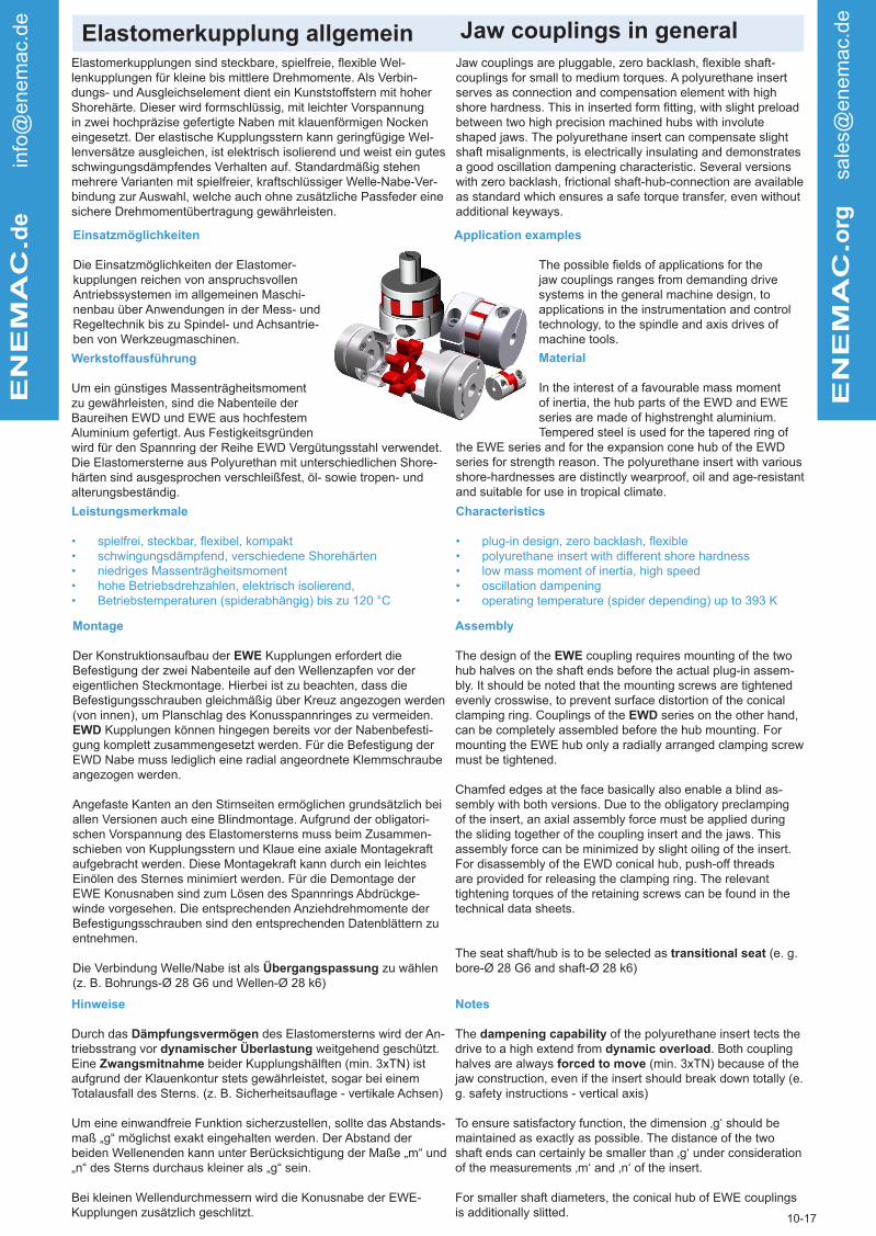
Elastomerkupplung allgemein Jaw couplings in generalENEMAC.d
e in
fo@
enem
ac.
de
ENEMAC.o
rg
sale
s@enem
ac.
de
Elastomerkupplungen sind steckbare, spielfreie, flexible Wel-lenkupplungen für kleine bis mittlere Drehmomente. Als Verbin-dungs- und Ausgleichselement dient ein Kunststoffstern mit hoher Shorehärte. Dieser wird formschlüssig, mit leichter Vorspannung in zwei hochpräzise gefertigte Naben mit klauenförmigen Nocken eingesetzt. Der elastische Kupplungsstern kann geringfügige Wel-lenversätze ausgleichen, ist elektrisch isolierend und weist ein gutes schwingungsdämpfendes Verhalten auf. Standardmäßig stehen mehrere Varianten mit spielfreier, kraftschlüssiger Welle-Nabe-Ver-bindung zur Auswahl, welche auch ohne zusätzliche Passfeder eine sichere Drehmomentübertragung gewährleisten.
Jaw couplings are pluggable, zero backlash, flexible shaft-couplings for small to medium torques. A polyurethane insert serves as connection and compensation element with high shore hardness. This in inserted form fitting, with slight preload between two high precision machined hubs with involute shaped jaws. The polyurethane insert can compensate slight shaft misalignments, is electrically insulating and demonstrates a good oscillation dampening characteristic. Several versions with zero backlash, frictional shaft-hub-connection are available as standard which ensures a safe torque transfer, even without additional keyways.
10-17
Einsatzmöglichkeiten
Die Einsatzmöglichkeiten der Elastomer-kupplungen reichen von anspruchsvollen Antriebssystemen im allgemeinen Maschi-nenbau über Anwendungen in der Mess- und Regeltechnik bis zu Spindel- und Achsantrie-ben von Werkzeugmaschinen.
Application examples
The possible fields of applications for the jaw couplings ranges from demanding drive systems in the general machine design, to applications in the instrumentation and control technology, to the spindle and axis drives of machine tools.
Werkstoffausführung
Um ein günstiges Massenträgheitsmoment zu gewährleisten, sind die Nabenteile der Baureihen EWD und EWE aus hochfestem Aluminium gefertigt. Aus Festigkeitsgründen wird für den Spannring der Reihe EWD Vergütungsstahl verwendet. Die Elastomersterne aus Polyurethan mit unterschiedlichen Shore-härten sind ausgesprochen verschleißfest, öl- sowie tropen- und alterungsbeständig.
Material
In the interest of a favourable mass moment of inertia, the hub parts of the EWD and EWE series are made of highstrenght aluminium. Tempered steel is used for the tapered ring of
the EWE series and for the expansion cone hub of the EWD series for strength reason. The polyurethane insert with various shore-hardnesses are distinctly wearproof, oil and age-resistant and suitable for use in tropical climate.
Leistungsmerkmale
• spielfrei, steckbar, flexibel, kompakt• schwingungsdämpfend, verschiedene Shorehärten• niedriges Massenträgheitsmoment • hohe Betriebsdrehzahlen, elektrisch isolierend, • Betriebstemperaturen (spiderabhängig) bis zu 120 °C
Characteristics
• plug-in design, zero backlash, flexible• polyurethane insert with different shore hardness• low mass moment of inertia, high speed• oscillation dampening• operating temperature (spider depending) up to 393 K
Montage
Der Konstruktionsaufbau der EWE Kupplungen erfordert die Befestigung der zwei Nabenteile auf den Wellenzapfen vor der eigentlichen Steckmontage. Hierbei ist zu beachten, dass die Befestigungsschrauben gleichmäßig über Kreuz angezogen werden (von innen), um Planschlag des Konusspannringes zu vermeiden. EWD Kupplungen können hingegen bereits vor der Nabenbefesti-gung komplett zusammengesetzt werden. Für die Befestigung der EWD Nabe muss lediglich eine radial angeordnete Klemmschraube angezogen werden.
Angefaste Kanten an den Stirnseiten ermöglichen grundsätzlich bei allen Versionen auch eine Blindmontage. Aufgrund der obligatori-schen Vorspannung des Elastomersterns muss beim Zusammen-schieben von Kupplungsstern und Klaue eine axiale Montagekraft aufgebracht werden. Diese Montagekraft kann durch ein leichtes Einölen des Sternes minimiert werden. Für die Demontage der EWE Konusnaben sind zum Lösen des Spannrings Abdrückge-winde vorgesehen. Die entsprechenden Anziehdrehmomente der Befestigungsschrauben sind den entsprechenden Datenblättern zu entnehmen.
Die Verbindung Welle/Nabe ist als Übergangspassung zu wählen (z. B. Bohrungs-Ø 28 G6 und Wellen-Ø 28 k6)
Assembly
The design of the EWE coupling requires mounting of the two hub halves on the shaft ends before the actual plug-in assem-bly. It should be noted that the mounting screws are tightened evenly crosswise, to prevent surface distortion of the conical clamping ring. Couplings of the EWD series on the other hand, can be completely assembled before the hub mounting. For mounting the EWE hub only a radially arranged clamping screw must be tightened.
Chamfed edges at the face basically also enable a blind as-sembly with both versions. Due to the obligatory preclamping of the insert, an axial assembly force must be applied during the sliding together of the coupling insert and the jaws. This assembly force can be minimized by slight oiling of the insert. For disassembly of the EWD conical hub, push-off threads are provided for releasing the clamping ring. The relevant tightening torques of the retaining screws can be found in the technical data sheets.
The seat shaft/hub is to be selected as transitional seat (e. g. bore-Ø 28 G6 and shaft-Ø 28 k6)
Hinweise
Durch das Dämpfungsvermögen des Elastomersterns wird der An-triebsstrang vor dynamischer Überlastung weitgehend geschützt. Eine Zwangsmitnahme beider Kupplungshälften (min. 3xTN) ist aufgrund der Klauenkontur stets gewährleistet, sogar bei einem Totalausfall des Sterns. (z. B. Sicherheitsauflage - vertikale Achsen)
Um eine einwandfreie Funktion sicherzustellen, sollte das Abstands-maß „g“ möglichst exakt eingehalten werden. Der Abstand der beiden Wellenenden kann unter Berücksichtigung der Maße „m“ und „n“ des Sterns durchaus kleiner als „g“ sein.
Bei kleinen Wellendurchmessern wird die Konusnabe der EWE-Kupplungen zusätzlich geschlitzt.
Notes
The dampening capability of the polyurethane insert tects the drive to a high extend from dynamic overload. Both coupling halves are always forced to move (min. 3xTN) because of the jaw construction, even if the insert should break down totally (e. g. safety instructions - vertical axis)
To ensure satisfactory function, the dimension ‚g‘ should be maintained as exactly as possible. The distance of the two shaft ends can certainly be smaller than ‚g‘ under consideration of the measurements ‚m‘ and ‚n‘ of the insert.
For smaller shaft diameters, the conical hub of EWE couplings is additionally slitted.

Elastomerkupplung Auslegung Jaw couplings dimensioningENEMAC.d
e in
fo@
enem
ac.
de
ENEMAC.o
rg
sale
s@enem
ac.
de
Kupplungsauslegung
Die wesentlichen Auslegungskriterien sind das erforderliche Antriebsmoment, die notwendige Torsionssteifigkeit, das Dämp-fungsverhalten oder das Trägheitsmoment der Kupplungen. Zu-sätzlich können weitere technische Parameter wie die maximale Drehzahl, der Temperaturbereich, vorhandene Fluchtungsfehler und Wellendurchmesser von Bedeutung sein.
Coupling dimensioning
The important layout criterias are the required drive torque, the necessary torsional stiffness and the dampening characteristic of the coupling. Additionally, the minimium or maximum possible shaft diameter, the admissible tempera-ture range, operating factors and the existing shaft misa-lignment, particularly the radial displacement, must be taken into consideration. Basically, the selection can be influenced by the coupling size and the hardness of the polyurethane insert.
10-17
Berechnungsformel
Überschlägig kann das erforderliche Kupplungsmoment TK nach folgender Formel berechnet werden:.
Calculation formula
Roughly, the required coupling torque TK can be calculated according to the following formula:
Das errechnete Kupplungsmoment TK sollte das Nennmoment der ausgewählten Kupplungsgröße TKN nicht übersteigen. Kurzzeitige Überlastungen auf den zweifachen Wert des Nenn-momentes sind zulässig. Das Antriebsmoment ergibt sich aus den Herstellerangaben des Antriebsmotors oder kann mittels der Antriebsleistung P
A berechnet werden.
The calculated coupling torque TK should not exceed the nominal torque of the selected coupling size. Short term overload up to twice the value of the nominal torque is ad-missible. The drive torque results of producer information of drive motor or can be calculated via motor output P
A.
Temperaturfaktor fT
Temperature factor fT
Drehsteifigkeitsfaktor fD
Wird eine exakte, winkelgetreue Übertragung des Drehmo-mentes gefordert, wie zum Beispiel bei Servoantrieben oder Messystemen, ist eine hohe Verdrehsteifigkeit unabdingbar. Hierzu sollte bei der Größenauswahl das benötigte Antriebs-moment mit einem Multiplikationsfaktor von mindestens 3 bis 10 beaufschlagt werden, oder eine torsionssteife Metallbalg-kupplung Verwendung finden.
Torsional stiffness factor fD
If an exact, accurate transfer of the torque is required, as for instance with servo drives or measuring systems, a high tor-sional stiffness is absolutely necessary. Here the required drive torque should be multiplied with an operating factor of at least 3 to 10 when selecting the size, or a torsionally stiff metal bellows coupling should be chosen from the extensi-ve coupling range in the catalogue.
TK = T
A x f
D x f
T x f
B < T
KN
TA = Antriebsmoment [Nm]
fD = Drehsteifigkeitsfaktor
fT
= TemperaturfaktorfB
= Betriebsfaktor
TA
= drive torque[Nm]fD = torsional stiffness
fT
= temperature factorfB
= operating factor
9550 x PA
TA = n
B
TA = Antriebsmoment [Nm]
PA
= Antriebsleistung [kW]n
B = Betriebsdrehzahl [min-1]
TA = drive torque [Nm]
PA
= motor output [kW]n
B = motor speed [min-1]
Zulässiger Temperaturbereich für Dauerbetrieb
PUR 98 Sh-A -30 °C bis +90 °C rot
PUR 72 Sh-D -20 °C bis +120 °C weißPUR 80 Sh-A -20 °C bis +70 °C blau
admissible temperature range for continuous operation
PUR 98 Sh-A 243 K up to 363 K red
PUR 72 Sh-D 253 K up to 393 K white
PUR 80 Sh-A 253 K up to 343 K blue
Betriebs-temperatur
+30°C-30 °C +50 °C +70 °C +90 °C +110
°CFaktor f
T1 1,3 1,6 1,8 2
operatingtemperature
303 K243 K 323 K 343 K 363 K 383 K
factor fT
1 1,3 1,6 1,8 2
Betriebsfaktor fB
Durch den Betriebsfaktor fB (1,5-2,5) sind anwendungsspezi-fische Besonderheiten, wie zum Beispiel stoßartige Belastun-gen, zu berücksichtigen.
Operating factor fB
By the operating factor fB (1,5-2,5) application specific peculiarities, such as shock loading, are taken into conside-

ENEMAC.d
e in
fo@
enem
ac.
de
ENEMAC.o
rg
sale
s@enem
ac.
de
Abmessungen Elastomerstern [mm] Dimensions - polyurethane insert [mm]
10-17
Größe Size
Øs Øm n o Øp +0,5
8 / 10 32 10,5 2 10 8,515 / 17 / 20 / 25 40 18 3 12 9,530 / 43 / 45 / 50 50 27 3 14 12,5
60 / 90 55 27 3 14 12,5150 / 200 65 30 4 18 16,5
300 / 320 / 400 80 38 4 18 16,5500 100 47 5 22 20,5
700 / 1000 120 58 6 25 22,52000 160 77 7 38 60
Bemerkung
Der Durchmesser ‚p‘ der Innenbohrung des Sterns kann auf Kundenwunsch, falls anwendungsspezifisch erforderlich ( z. B. Wellendurchgang) bis auf max. Øm - 2 mm vergrößert werden.
Note
If required by the customer due to special application (e. g. longer shaft plug-in depth), diameter ‚p‘ of the inner bore of the insert can be extended up to max Øm - 2 mm.
Op
Om
Os
n
50x4
5
o
Werkstoff
• Polyurethan• 98 Shore-A / rot• 72 Shore-B / weiß• 80 Shore-A /blau
Material
• Polyurethane• 98 Shore-A / red• 72 Shore-B / white• 80 Shore-A /blue

Elastomerkupplung EWD Jaw coupling EWD
Technische Daten / technical data:
• mit beidseitiger radialer Klemmnabe• steckbar, spielfrei• kostengünstige, kompakte Standardbaureihe
• radial clamping hub on both sides• plug-in, zero backlash• cost-effective standard type
Abmessungen nach / dimensions acc. to DIN ISO 2768 cH:
ENEMAC.d
e in
fo@
enem
ac.
de
ENEMAC.o
rg
sale
s@enem
ac.
de
7-17
EWD 8 15 20 30 45 60 90 150 200 300 400 500 700 1000
Nennmoment nominal torque
[Nm] 8 15 20 30 45 60 90 150 200 300 400 500 700 1000
Trägheitsmomentmoment of inertia
[10-3kgm2] 0,01 0,03 0,03 0,09 0,09 0,18 0,18 0,38 0,38 1,0 1,0 2,2 5,2 5,2
Torsionssteifetorsional stiffness
[Nm/arcmin] 0,09 0,24 0,46 0,41 0,75 1,0 2,0 1,2 2,3 3,6 7,0 4,5 8,0 12,0
Drehzahl max. max. speed
[min-1] 20.000 19.000 19.000 15.000 15.000 13.000 13.000 11.000 11.000 9.000 9.000 7.500 6.500 6.500
Wellenversatz max.shaft displace-ment
axial ± [mm] 0,5 0,5 0,5 0,5 0,5 0,5 0,5 1 1 1 1 1 1 1
lateral [mm] 0,1 0,1 0,07 0,1 0,07 0,1 0,07 0,1 0,07 0,12 0,1 0,15 0,15 0,1
Federsteifespring rate
radial [N/mm] 600 2100 2900 2500 3600 2600 3700 3300 4600 4500 6500 5900 7000 9600
Masse ca. weight approx.
[kg] 0,06 0,12 0,12 0,21 0,21 0,32 0,32 0,52 0,52 0,9 0,9 1,5 2,5 2,5
HärteHardness
[shore]98
Sh-A98
Sh-A72
Sh-D98
Sh-A72
Sh-D98
Sh-A72
Sh-D98
Sh-A72
Sh-D98
Sh-A72
Sh-D98
Sh-A98
Sh-A72
Sh-D
Anziehmoment f / f*tightening torque f / f*
[Nm] 4 8 8 14 14 35 3565 50*
65 50*
115 90*
115 90*
115 90*
180 140*
180 140*
Werkstoff:Elastomerstern: PolyurethanKlemmnaben: hochfestes AluminiumSchrauben: ISO 4762 12.9
EWD 8 15 20 30 45 60 90 150 200 300 400 500 700 1000
Øa [mm] 32 40 40 50 50 60 60 70 70 85 85 100 120 120
c[mm]
10,5 13 13 16,5 16,5 19,5 19,5 23 23 29 2936 44 44
c** - - - 18 18 20 20 25 25 30 30
e [mm] 13,5 17 17 20 20 22 22 26,5 26,5 31 31 33 38 38
f / f* M4 M5 M5 M6 M6 M8 M8 M10 M10 M12 M12 M12 M14 M14
f** - - - M5 M5 M6 M6 M8 M8 M10 M10 - - -
g [mm] 13 16 16 18 18 18 18 20 20 24 24 28 33 33
h [mm] 6 8 8 9 9 10 10 12 12 14 14 16 18 18
L [mm] 40 50 50 58 58 62 62 73 73 86 86 94 109 109
Ø D1/2 min. [mm] 8 8 10 10 15 13 16 18 20 20 24 28 32 42
Ø D1/2 max. f / f* [mm] 15 20 20 25 25 28 2827 32*
27 32*
34 40*
34 40*
48 56*
60 70*
6070*
Ø D1/2 max. f** [mm] - - - 30 30 32 32 38 38 48 48 - - -
Anziehmoment f**tightening torque f**
[Nm] - - - 8 8 14 14 35 35 65 65 - - -
Temperaturbereich: 98 Sh-A: -30 °C bis +90 °C / 72 Sh-D: -20 °C bis +120 °Cf ist Standardausführung analog cf* ist Standardausführung mit größerem D1/D2 max., kleinere Anzugsmomente beachten analog cf** größere D1/D2 max. möglich durch kleinere Gewinde, kleinere Anzugsmomente beachten, analog c**
temperature range: 98 Sh-A: 243 K up to 363 K / 72 Sh-D: 253 up to 393 K
f is standard version, analogue cf* is standard version with bigger D1/D2 max., consider reduced tightening torques
analogue cf** bigger D1/D2 max possible through smaller threads, consider reduced,
analogue c**
Bestellbeispiel / ordering example: EWD 90 - D1 = 24 H7 - D2 = 28 H7
material:polyurethane inserthubs: high tensile aluminiumscrews: ISO 4762 12.9
f - ISO 4762
auf Anfrage Nennmomente bis zu 2000 Nm erhältlich / on request for torques up to 2000 Nm

Elastomerkupplung EWE Jaw coupling EWE
Technische Daten / technical data:
• mit beidseitiger Konus-Spannringnabe
• steckbar, spielfrei
• rotationssymmetrischer Aufbau, hohe Drehzahlen
• with conical hub and clamping ring
• plug-in, zero backlash
• rotary symmetric design, high speed
Abmessungen nach / dimensions acc. to DIN ISO 2768 cH:
EN
EM
AC
.de info
@enem
ac.
de
EN
EM
AC
.org
sale
s@enem
ac.
de
21-17
EWE 10 17 25 43 50 60 90 150 200 320 400 500 700 1000
Nennmoment nominal torque
[Nm] 10 17 25 43 50 60 90 150 200 320 400 500 700 1000
Trägheitsmomentmoment of inertia
[10-3kgm2] 0,015 0,05 0,06 0,19 0,19 0,28 0,28 0,65 0,65 2,0 2,0 5,6 13,0 13,0
Torsionssteifetorsional stiffness [Nm/arcmin] 0,09 0,24 0,46 0,41 0,75 1,0 2,0 1,2 2,3 3,6 7,0 4,5 8,0 12
max. Drehzahlmax.speed
[min-1] 30.000 24.000 24.000 19.000 19.000 17.500 17.500 15.000 15.000 12.000 12.000 9.500 8.000 8.000
Wellenversatzmax. shaft displace-ment
axial ± [mm] 0,5 0,5 0,5 0,5 0,5 0,5 0,5 1 1 1 1 1 1 1
lateral [mm] 0,1 0,1 0,07 0,1 0,07 0,1 0,07 0,1 0,07 0,12 0,1 0,15 0,15 0,15
Federsteifespring rate
radial [N/mm] 600 2100 2900 2500 3600 2600 3700 3300 4600 4500 6500 5900 7000 9600
Masse ca.weight approx.
[kg] 0,11 0,28 0,28 0,4 0,4 0,6 0,6 0,9 0,9 1,9 1,9 4,5 7,0 7,0
HärteHardness
[shore]98
Sh-A98
Sh-A72
Sh-D98
Sh-A72
Sh-D98
Sh-A72
Sh-D98
Sh-A72
Sh-D98
Sh-A72
Sh-D98
Sh-A98
Sh-A72
Sh-D
Anziehmoment d. Schraubentightening torque of screws
[Nm] 2 4 4 8 8 8 8 8 8 35 35 65 115 115
EWE 10 17 25 43 50 60 90 150 200 320 400 500 700 1000
Øa [mm] 32 40 40 50 50 55 55 65 65 80 80 100 120 120
Øb [mm] 17 22 22 29 29 30 30 40 40 46 46 58 72 72
e [mm] 18,5 25 25 30 30 30 30 35 35 45 45 55 61 61
f 4xM3 6xM4 6xM4 4xM5 4xM5 4xM5 4xM5 8xM5 8xM5 4xM8 4xM8 4xM10 4xM12 4xM12
g [mm] 13 16 16 18 18 18 18 20 20 24 24 28 33 33
k [mm] 15,5 21 21 25 25 25 25 30 30 40 40 49 54 54
L [mm] 50 66 66 78 78 78 78 90 90 114 114 138 155 155
Ø D1/2 min. [mm] 6 9 10 12 15 13 16 17 19 20 25 22 25 25
Ø D1/2 max. [mm] 14 19 19 24 24 26 26 36 36 40 40 48 60 60
vorgebohrtprebored
[mm] 5 9 9 10 10 12 12 12 12 18 18 20 24 24
Temperaturbereich: -30 bis +120 °C
Auf Anfrage für Nennmomente bis zu 2000 Nm erhältlich.
temperature range: 243,15 K up to 393,15 K
On request available for torques up to 2000 Nm.
Bestellbeispiel / ordering example: EWE 150 - D1 = 19 H7 - D2 = 22 H7
Werkstoff:Elastomerstern: PolyurethanKonusnabe: hochfestes Aluminium (Größe 2000: Vergütungsstahl)Spannring: Vergütungsstahl brüniertSchrauben: ISO 4762 vernickelt
material:
insert: polyurethaneconical hub: high tensile aluminium (type 2000: tempered steel)clamping ring: tempered steel black finished
f - ISO 4762

Elastomerkupplung EWN Jaw coupling EWN
Technische Daten / technical data:
• beidseitige montagefreundliche Halbschalennabe
• steckbar
• spielfrei
• easy installation due to splitted hub design
• pluggable
• zero backlash
Abmessungen nach / dimensions acc. to DIN ISO 2768 cH:
EN
EM
AC
.de info
@enem
ac.
de
EN
EM
AC
.org
sale
s@enem
ac.
de
47-17
EWN 15 20 30 45 60 90 150 200 300 400 700 1000 2000
Nennmoment nominal torque
[Nm] 15 20 30 45 60 90 150 200 300 400 700 1000 2000
Trägheitsmomentmoment of inertia
[10-3kgm2] 0,03 0,03 0,09 0,09 0,2 0,2 0,4 0,4 1,0 1,0 6,0 6,0 62
Torsionssteifetorsional stiffness [Nm/arcmin] 0,24 0,34 0,41 0,58 0,6 0,9 1,0 1,5 2,0 2,8 8,0 12 21
max. Drehzahlmax.speed
[min-1] 19.000 19.000 15.000 15.000 13.000 13.000 11.000 11.000 9.000 9.000 7.500 6.500 6.500
max. Wellenver-satz
axial ± [mm] 0,5 0,5 0,5 0,5 0,5 0,5 1 1 1 1 1 1 1
max. shaft displacement
lateral [mm] 0,10 0,07 0,10 0,07 0,10 0,07 0,10 0,07 0,12 0,10 0,15 0,10 0,15
Federsteifespring rate
axial [N/mm] 2100 2900 2500 3600 2600 3700 3300 4600 4500 6500 7000 9600 9000
HärteHardness
[Shore]98
Sh-A72
Sh-D98
Sh-A72
Sh-D98
Sh-A72
Sh-D98
Sh-A72
Sh-D98
Sh-A72
Sh-D98
Sh-A72
Sh-D98
Sh-A
Masse ca.weight approx.
[kg] 0,17 0,17 0,30 0,30 0,50 0,50 0,75 0,75 1,3 1,3 3,2 3,2 18,5
Anziehmoment der Schraubentigthening torque of screws
[Nm] 8 8 14 14 35 35 65 65 115 115 180 180 290
EWN 15 20 30 45 60 90 150 200 300 400 700 1000 2000
Øa [mm] 40 40 50 50 60 60 70 70 85 85 120 120 160
Øa* [mm] 42 42 52 52 63 63 76 76 91 91 125 125 165
c [mm] 27 27 34 34 41 41 48 48 58 58 90 90 122
g [mm] 26 26 30 30 30 30 32 32 40 40 53 53 64
h [mm] 8,5 8,5 10 10 11,5 11,5 14 14 15 15 18 18 24
t [mm] 16 16 18 18 22 22 26 26 28 28 34 34 43
L [mm] 62 62 72 72 78 78 89 89 102 102 127 127 156
f M5 M5 M6 M6 M8 M8 M10 M10 M12 M12 M14 M14 M16
Ø D1/2 min.[mm]
8 10 10 15 13 16 18 20 20 24 32 42 48
Ø D1/2 max. 20 20 26 26 30 30 35 35 42 42 70 70 100
Temperaturbereich: 98 Sh-A: -30 °C bis +90 °C / 72 Sh-D: -20 °C bis +120 °C
Zur Montageerleichterung können die festen Nabenhälften auf die Wellenzapfen aufgelegt und die losen Habschalenstücke verschraubt werden. Im Servicefall ent-fällt die umständliche Demontage der Antriebs- und Abtriebsaggregate. Der Abstand zwischen Antriebs- und Abtriebswelle muss größer sein als Maß „g“.
temperature range: 98 Sh-A: 243 K up to 363 K / 72 Sh-D: 253 K up to 393 K
For easy assembly, the fixed hub halves can be placed on the shaft jounal
and the loose hub pieces can be screwed on. In case of service, the compli-cated disassembly of the drive and output units isn‘t necessary.
The distance between the drive shaft and the output shaft must be greater than the dimension „g“.
Bestellbeispiel / ordering example: EWN 200 - D1 = 26 H7 - D2 = 32 H7
Werkstoff:Elastomerstern: PolyurethanHalbschalennaben: hochfestes Aluminium (Gr. 2000 Vergütungsstahl) Schrauben: ISO 4762 / 12.9 beschichtet
material:
elastomer insert: polyurethanesplitted hubs: high-tensile aluminium (size 2000 tempered steel)screws: ISO 4762 / 12.9 coated

Distanzkupplung allgemein Distance couplings in generalE
NE
MA
C.d
e info
@enem
ac.
de
EN
EM
AC
.org
sale
s@enem
ac.
de
DefinitionDistanzkupplungen:
Unter der Rubrik Distanzkupplungen wurden mehrere Kupplungs-baureihen zur Überbrückung von Achsabständen von bis zu 6 m Länge zusammengefasst. Gemeinsames konstruktives Merkmal aller Typen ist ein längenvariables Zwischenrohr, das dem kunden-spezifischen Anwendungsfall optimal angepasst werden kann. In vielen Fällen können sie als spielfreie Verbindungs-, Gelenk- oder Synchronwelle eingesetzt werden und konventionelle Zwischenwel-len-Konstruktionen mit aufwendiger, zusätzlicher Zwischenlagerung ersetzen. Fluchtungsfehler, besonders Parallelversatz, können in erheblicher Größenordnung kompensiert werden. Des Weiteren ist besonders die rostfreie Werkstoffausführung sowie die Montage-freundlichkeit aller Baureihen hervorzuheben. Aufgrund der Naben-ausführung in Halbschalenversion (Reihen EWLM und EWLA) bzw. als steckbare, axial verschiebbare Klauennabe (Reihen EWL und EWLH) wird eine sichere, kraftschlüssige Verbindung bei einfacher Bedienung gewährleistet.
Definitiondistancecouplings:
Several coupling series are combined under the name ‚dis-tance couplings‘. They are designed to bridge axle distances of up to 6 m in length. A common structural feature of all types is a variable intermediate pipe, which can be optimally adapted to the customer‘s specific application. In many cases, they can be used as a clearance-free connection, drive line or synchronous shaft and replace conventional intermediate shaft constructions with complex, additional intermediate bearings. Misalignments, especially parallel offset, can be compensated in a considerab-le dimensioin. Furthermore, the stainless steel material design as well as the mounting-friendlyness of all series are particu-larly noteworthy. Due to the hub design in half-shell version (EWLM and EWLA series) or as an axially slideable plug-in hub (EWL and EWLH series), a secure, non-positive connection is ensured with simple operation.
28-17
Leistungsmerkmale - Distanzkupplungen:
• Verbindungswellen ohne zusätzliche Zwischenlagerung
• bis zu 6 m Achsabstand
• hohe Torsionssteife
• spielfreie, exakte Drehmomentübertragung
• Ausgleich von großen Wellenversätzen
• sehr montagefreundlich
• rostfreie Variante
• wartungsfrei
• hohe Betriebsdrehzahlen
• Zwischenrohr optional aus Stahl, CFK, u. ä.
Characteristics - distance couplings:
• connection shafts without extra intermediate bearing
• up to 6 m axle distance
• hightorsionalstiffness• clearance-free, precise torque transmission
• compensation of large misalignments
• easy to assemble
• stainless version
• maintenance free
• high operating speeds
• intermediate pipe optionally made of steel, CFK
Auslegung der Distanzkupplung
Die Auslegung gleicht der der Wellenkupplungen im Allgemeinen (s. S. 4 und 5 im Katalog)
Dimensioning of the distance couplings:
The dimensioning is similar to shaft couplings in general(see pages 4 and 5 in the catalog)
Formel für die Längenbestimmung: Formula for length determination:
L = A + t1 + t2 [mm]A = Achsabstand ± 1t = Einstecktiefe ± 1(s. Datenblätter)
= dimension between axes ± 1= insertion depth ± 1(see datasheet)
At
Montage:
Die geteilte Halbschalennabe bzw. die steckbare Klemmnabe gewährleistet durch eine einfache, radiale Bedienung eine spiel-freie, kraftschlüssige Klemmverbindung. Zur Montageerleichterung können die festen Nabenhälften auf die Wellenzapfen aufgelegt und danach die losen Halbschalenstücke verschraubt werden. Bei den Baureihen EWL und EWLH erfolgt die Steckmontage mittels Schie-besitzes der rohrseitigen Klemmnabe. Dies ermöglicht generell eine Einmann-Montage, auch bei großen Baulängen und im Servicefall kann die zeitaufwendige Demontage der Antriebs- bzw. Abtriebs-aggregate entfallen.
Montage:
The splitted half-shell hub or the plug-in clamping hub ensures a clearance-free, non-positive clamping connection by simple, radial operation. To simplify assembly, the fixed hub halves can be placed on the journal extension and the loose half shell pieces can then be screwed. For types EWL and EWLH, the plug-in mounting is carried out by means of a sliding seat of the pipe-sided clamping hub. This generally permits a one-man installation, even with large installation lengths. In service case, the time-consuming disassembly of the drive and output units can be dispensed with.
HINWEIS:
Das Zwischenrohr kann in unterschiedlicher Werkstoffausführung sowie in gerichteter und gewuchteter Qualität geliefert werden. Bei hohen Betriebsdrehzahlen über 2000 min-1 und gleichzeitig großen Baulängen L > 2 m sollte aufgrund der zulässigen biegekritischen Drehzahlen eine Überprüfung durch unsere Techniker erfolgen. Eventuell können anwendungsspezifisch optimierte CFK-Zwischen-rohre eingesetzt werden.
HINWEIS:
The intermediate pipe can be supplied in various materials as well as in directed and balanced quality. At high operational speeds above 2000 rpm and simoultaneously large lengths L> 2 m, a check should be carried out by our technicians. It may be possible to use application-specific optimized CFK intermediate pipes.

Distanzkupplung EWL Distance coupling EWL
Technische Daten / Technical data:
• Elastomerkupplung mit Zwischenrohr• variable Baulängen bis 3 m• steckbar, spielfrei, schwingungsdämpfend• beidseitige Klemmnabe, einfache, schnelle Montage• rostgeschützte Ausführung
• Jaw coupling with intermediate pipe• customized length up to 3 m• plug-in, zero backlash, oscillation dampening• easy installation, radial clamping hub on both sides• corrossion-resistant version
Abmessungen nach / dimensions acc. to DIN ISO 2768 cH:
ENEMAC.d
e in
fo@
enem
ac.
de
ENEMAC.o
rg
sale
s@enem
ac.
de
23-16
EWL 20 45 90 200 400 700 1500
Nennmoment nominal torque
[Nm] 20 45 90 200 400 700 1500
Torsionssteifetorsional stiffness(stat bei / at 0,5xTN)
0,5 m
[Nm/arcmin]
0,15 0,28 0,42 0,7 1,4 5,7 7,5
1 m 0,13 0,26 0,38 0,63 1,3 5,1 8,5
2 m 0,11 0,23 0,31 0,53 1,1 4,3 7
3 m -- 0,2 0,27 0,46 1 3,7 6
Trägheitsmomentmoment of inertia
0,5 m
[10-3kgm2]
0,14 0,44 0,64 1,2 3,2 12,6 95
1 m 0,23 0,79 1 1,8 5,1 17 100
2 m 0,42 1,5 1,7 3 8,9 26 115
3 m -- 2,2 2,4 4,2 12,7 35 130
max. Drehzahlmax. speed
0,5 m
[min-1]
3.500 3.500 3.500 3.500 3.500 3.500 3.500
1 m 2.700 3.500 3.500 3.500 3.500 3.500 3.500
2 m 680 990 990 1.600 1.600 2.000 2.000
3 m -- 440 440 720 720 880 890
Masse ca.mass approx.
0,5 m
[kg]
0,6 1 1,2 1,8 2,8 6,3 26
1 m 0,9 1,6 1,8 2,5 3,8 8,3 26
2 m 1,6 2,9 3 4 5,8 12 31
3 m -- 4,1 4,3 5,5 7,8 16 36
Anziehmoment Schraubetightening torque screws
[Nm] 8 14 35 65 115 180 290
Werkstoff:Naben: hochfestes Aluminium Zwischenrohr: Aluminium, optional StahlElastomerstern: PUR-72Sh-DSchrauben: ISO 4762 vernickelt
EWL 20 45 90 200 400 700 1500
Øa [mm] 40 50 60 70 85 120 160
Øb [mm] 35 50 50 60 80 100 120
Øc [mm] 13 16,5 19,5 23 29 44 56
f M5 M6 M8 M10 M12 M14 M16
h [mm] 8 9 10 12 14 18 21
k [mm] 50 58 62 73 86 109 124
Lmin
[mm] 132 152 160 186 220 284 330
s [mm] 16 18 18 20 24 33 40
tmin
[mm] 16 18 20 23 28 35 35
tmax
[mm] 20 25 26 30 35 42 45
Ø D1/2 min. [mm] 10 13 15 22 30 40 50
Ø D1/2 max. [mm] 20 26 29 33 42 70 90
Temperaturbereich: -30 bis +120 °C
Schiebenabe der Baugröße 400 mit Klemmschraube M10; TA=65 Nm
Temperature range: 243,15 K up to 393,15 K
Shifting hub of size 400 with clamping screw M10 = 65 Nm
Bestellbeispiel / Ordering example: EWL 200 - D1 = 32 H7 - D2 = 28 H7 - L = 660
Material:Hubs: high tensile aluminium Intermediate pipe: aluminium, alternatively steelInsert: PUR-72Sh-DScrews: ISO 4762 nickel plated
k s
L
Ob
OD
2
th
OD
1
c
Oa
f-DIN 912f - ISO 4762
Verschiebeweg NabeShift back hub
EinstecktiefePlug-in depth
Max. zul. Axialversatz ±1 mm Max. axial misalignment ± 1 mm
Max. zul. Lateralversatz 5 mm / mMax. lateral misalignment 5 mm / m

Distanzkupplung EWLH Distance coupling EWLH
Technische Daten / technical data:
• Elastomerkupplung mit Zwischenrohr
• variable Baulängen bis 3 m
• steckbar, spielfrei, schwingungsdämpfend
• beidseitige Halbschalennaben
• rostgeschützte Ausführung
• jaw coupling with intermediate pipe
• customized length up to 3 m
• plug-in, zero backlash, oscillation dampening
• easy installation, splitted hub design on both sides
• corrosion-resistant version
Abmessungen nach / dimensions acc. to DIN ISO 2768 cH:
EN
EM
AC
.de info
@enem
ac.d
e
EN
EM
AC
.org
sale
s@
enem
ac.d
e
19-18
EWLH 20 45 90 200 400 800 1600
Nennmoment
nominal torque[Nm] 20 45 90 200 400 800 1600
Torsionssteife
torsional stiffness(stat bei / at 0,5xT
N)
0,5 m
[Nm/arcmin]
0,19 0,35 0,85 0,99 2,9 5,7 10,2
1 m 0,16 0,32 0,76 0,90 2,5 5,3 9,7
2 m 0,12 0,27 0,62 0,75 1,9 4,7 8,8
3 m 0,09 0,24 0,52 0,65 1,55 4,2 8,1
Trägheitsmoment
moment of inertia
0,5 m
[10-3kgm2]
0,14 0,48 0,8 1,4 3,2 14,7 87
1 m 0,23 0,82 1,4 2,4 5,1 22,9 107
2 m 0,42 1,53 2,6 4,3 8,9 39,3 147
3 m 0,61 2,2 3,8 6,2 12,7 55,7 187
max. Drehzahl
max. speed
0,5 m
[min-1]
3.500 3.500 3.500 3.500 3.500 3.500 3.500
1 m 2.700 3.500 3.500 3.500 3.500 3.500 3.500
2 m 680 990 1.200 1.400 1.600 2.400 2.000
3 m 300 440 530 600 700 1.070 1.650
Masse ca.
mass approx.
0,5 m
[kg]
0,5 0,9 1,3 1,7 2,5 5,8 22
1 m 0,9 1,5 2,0 2,5 3,5 8,2 25
2 m 1,6 2,8 3,5 4,3 5,5 13,1 32
3 m 2,3 4,0 5,0 6,0 7,5 18 39
Anziehmoment Schraube
tightening torque screws[Nm] 8 14 35 65 115 180 290
Werkstoff:Naben: hochfestes Aluminium (Gr. 1600: Stahl)
Zwischenrohr: hochfestes Aluminium
Elastomerstern: PUR-72Sh-D
Schrauben: ISO 4762 / 12.9 beschichtet
EWLH 20 45 90 200 400 800 1600
Øa [mm] 40 50 60 70 85 120 160
Øa* [mm] 42 52 63 76 91 126 165
Øb [mm] 35 50 60 70 80 120 160
c [mm] 27 34 41 48 58 90 122
f M5 M6 M8 M10 M12 M14 M16
h [mm] 8,5 10 11,5 14 15 18 24
k [mm] 43 50 53 59 71 85 105
Lmin
[mm] 130 140 155 170 215 250 320
t [mm] 16 19 22 26 28 34 43
Ø D1/2 min. [mm] 10 15 16 20 24 32 48
Ø D1/2 max. [mm] 20 26 30 35 42 70 100
Temperaturbereich: -30 bis +90 °C
Øa* = Störkante Schraubenkopf
temperature range: 243 K up to 363 K
Øa* = interfering edge of the screw-head
Bestellbeispiel / ordering example: EWLH 90 - D1 = 28 H7 - D2 = 24 H7 - L = 1.250
material:
hubs: high tensile aluminium (size 1600: steel)
intermediate pipe: aluminium
elastomer insert: PUR-72Sh-D
screws: ISO 4762 / 12.9 coated
Max. zul. Axialversatz: ±1 mm
max. axial misalignment: ± 1 mm
Max. zul. Lateralversatz: 5 mm / m
max. lateral misalignment: 5 mm / m
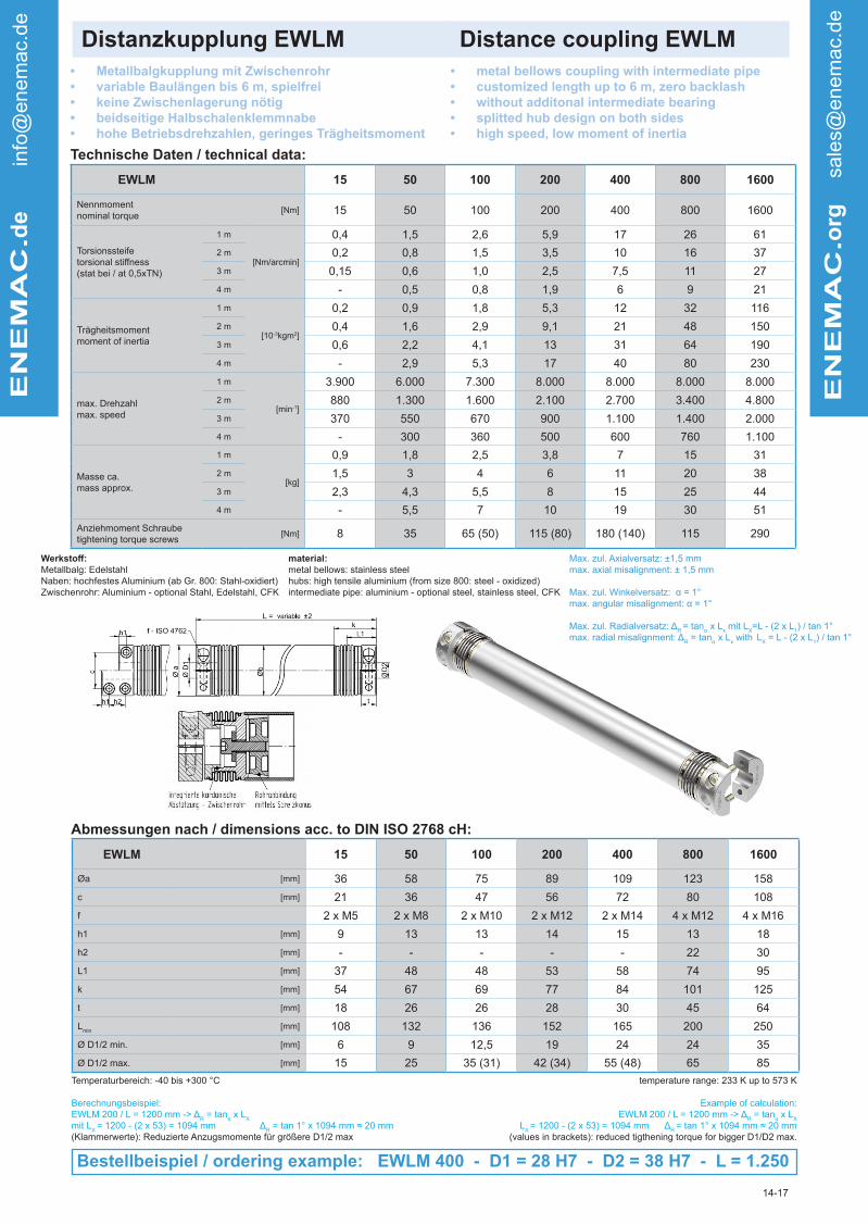
Distanzkupplung EWLM Distance coupling EWLM
Technische Daten / technical data:
• Metallbalgkupplung mit Zwischenrohr• variable Baulängen bis 6 m, spielfrei• keine Zwischenlagerung nötig• beidseitige Halbschalenklemmnabe• hohe Betriebsdrehzahlen, geringes Trägheitsmoment
• metal bellows coupling with intermediate pipe• customized length up to 6 m, zero backlash• without additonal intermediate bearing
• splitted hub design on both sides • high speed, low moment of inertia
Abmessungen nach / dimensions acc. to DIN ISO 2768 cH:
EN
EM
AC
.de in
fo@
enem
ac.d
e
EN
EM
AC
.org
sale
s@
enem
ac.d
e
14-17
EWLM 15 50 100 200 400 800 1600
Nennmoment
nominal torque[Nm] 15 50 100 200 400 800 1600
Torsionssteife
torsional stiffness(stat bei / at 0,5xTN)
1 m
[Nm/arcmin]
0,4 1,5 2,6 5,9 17 26 61
2 m 0,2 0,8 1,5 3,5 10 16 37
3 m 0,15 0,6 1,0 2,5 7,5 11 27
4 m - 0,5 0,8 1,9 6 9 21
Trägheitsmoment
moment of inertia
1 m
[10-3kgm2]
0,2 0,9 1,8 5,3 12 32 116
2 m 0,4 1,6 2,9 9,1 21 48 150
3 m 0,6 2,2 4,1 13 31 64 190
4 m - 2,9 5,3 17 40 80 230
max. Drehzahl
max. speed
1 m
[min-1]
3.900 6.000 7.300 8.000 8.000 8.000 8.000
2 m 880 1.300 1.600 2.100 2.700 3.400 4.800
3 m 370 550 670 900 1.100 1.400 2.000
4 m - 300 360 500 600 760 1.100
Masse ca.
mass approx.
1 m
[kg]
0,9 1,8 2,5 3,8 7 15 31
2 m 1,5 3 4 6 11 20 38
3 m 2,3 4,3 5,5 8 15 25 44
4 m - 5,5 7 10 19 30 51
Anziehmoment Schraube
tightening torque screws[Nm] 8 35 65 (50) 115 (80) 180 (140) 115 290
Werkstoff:Metallbalg: Edelstahl
Naben: hochfestes Aluminium (ab Gr. 800: Stahl-oxidiert)
Zwischenrohr: Aluminium - optional Stahl, Edelstahl, CFK
EWLM 15 50 100 200 400 800 1600
Øa [mm] 36 58 75 89 109 123 158
c [mm] 21 36 47 56 72 80 108
f 2 x M5 2 x M8 2 x M10 2 x M12 2 x M14 4 x M12 4 x M16
h1 [mm] 9 13 13 14 15 13 18
h2 [mm] - - - - - 22 30
L1 [mm] 37 48 48 53 58 74 95
k [mm] 54 67 69 77 84 101 125
t [mm] 18 26 26 28 30 45 64
Lmin
[mm] 108 132 136 152 165 200 250
Ø D1/2 min. [mm] 6 9 12,5 19 24 24 35
Ø D1/2 max. [mm] 15 25 35 (31) 42 (34) 55 (48) 65 85
Temperaturbereich: -40 bis +300 °C
Berechnungsbeispiel:
EWLM 200 / L = 1200 mm -> ΔR = tanα x L
X
mit LX = 1200 - (2 x 53) = 1094 mm Δ
R = tan 1° x 1094 mm ≈ 20 mm
(Klammerwerte): Reduzierte Anzugsmomente für größere D1/2 max
temperature range: 233 K up to 573 K
Example of calculation:
EWLM 200 / L = 1200 mm -> ΔR = tanα x L
X
LX = 1200 - (2 x 53) = 1094 mm Δ
R = tan 1° x 1094 mm ≈ 20 mm
(values in brackets): reduced tigthening torque for bigger D1/D2 max.
Bestellbeispiel / ordering example: EWLM 400 - D1 = 28 H7 - D2 = 38 H7 - L = 1.250
material:metal bellows: stainless steel
hubs: high tensile aluminium (from size 800: steel - oxidized)
intermediate pipe: aluminium - optional steel, stainless steel, CFK
Max. zul. Axialversatz: ±1,5 mm
max. axial misalignment: ± 1,5 mm
Max. zul. Winkelversatz: α = 1°max. angular misalignment: α = 1°
Max. zul. Radialversatz: ΔR
= tanα x Lx mit L
X=L - (2 x L
1) / tan 1°
max. radial misalignment: ΔR = tanα x L
x with
L
X = L - (2 x L
1) / tan 1°

Distanzkupplung EWLA Distance coupling EWLA
Technische Daten / technical data:
• kostengünstige Version mit reduzierten Betriebsparametern
• variable Baulänge bis 3 m
• montagefreundliche Halbschalen-Klemmnabe
• spielfrei, exakte Drehmomentübertragung
• keine Zwischenlagerung notwendig
• cost-effectiveversionwithreducedparameters• variable length up to 3 m
• splitted hub design on both sides
• without additonal intermediate bearing
EN
EM
AC
.de in
fo@
enem
ac.d
e
EN
EM
AC
.org
sale
s@
enem
ac.d
e
26-17
EWLA 40 80 160 250 500
Nennmoment
nominal torque[Nm] 40 80 160 250 500
Maximalmoment
max. torque[Nm] 80 160 320 500 1000
Torsionssteife
torsional stiffness
1 m
[Nm/arcmin]
0,46 1,1 2,0 4,9 10,5
2 m 0,23 0,5 1,0 2,4 5,2
3 m 0,15 0,4 0,6 1,6 3,5
Massenträgheitsmoment
moment of inertia
1 m
[10-3kgm2]
0,4 1,2 2,0 4,8 10,5
2 m 0,6 1,6 2,7 6,7 14,5
3 m 0,8 2,0 3,4 8,7 18,5
max. Drehzahl
max. speed
1 m
[min-1]
2.900 3.000 3.000 3.000 3.000
2 m 700 900 1.100 1.500 1.900
3 m 300 400 500 650 850
Masse
mass
1 m
[kg]
1,1 1,7 2,3 3,6 5,3
2 m 1,8 2,6 3,4 5,4 7,5
3 m 2,5 3,5 4,6 7,1 9,7
Anziehmoment Schraube
tightening torque screws[Nm] 14 35 (30) 65 (50) 115 (90) 180 (140)
Werkstoff:Metallbalg: Edelstahl
Naben: hochfestes Aluminium
Zwischenrohr: Aluminium
EWLA 40 80 160 250 500
Øa [mm] 57 72 83 103 123
Øb [mm] 35 45 55 70 90
c [mm] 38 50 57 70 87
f 2 x M6 2 x M8 2 x M10 2 x M12 2 x M14
h [mm] 8 9,5 10,5 12,5 15
L1 [mm] 37 40 45 49 61
k [mm] 62 72 84,5 92,5 109
t [mm] 16 18 21 24 30
Lmin
[mm] 112 124 144 155 190
Ø D1/2 min. [mm] 14 22 22 25 32
Ø D1/2 max. [mm] 30 38 (31) 43 (37) 55 (44) 70 (54)
Temperaturbereich: -40 bis +90 °C
Berechnungsbeispiel:
EWLA 80 / L = 900 mm -> ΔR = tanα x L
X
mit LX = 900 - (2 x 40) = 820 mm Δ
R = tan 1° x 820 mm ≈ 14 mm
(Klammerwerte): Reduzierte Anzugsmomente für größere D1/2 max
temperature range: 233 K up to 363 K
Example of calculation:
EWLA 80 / L = 900 mm -> ΔR = tanα x L
X
LX = 900 - (2 x 40) = 820 mm Δ
R = tan 1° x 820 mm ≈ 14 mm
(values in brackets): reduced tigthening torque for bigger D1/D2 max.
Bestellbeispiel / ordering example: EWLA 250 - D1 = 28 H7 - D2 = 38 H7 - L = 980
material:metal bellows: stainless steel
hubs: high tensile aluminium
intermediate pipe: aluminium
EWLA mit integrierter kardanischer
Abstützung - Zwischenrohr
Max. zul. Axialversatz: ±1,5 mm
max. axial misalignment: ± 1,5 mm
Max. zul. Winkelversatz: α = 1°max. angular misalignment: α = 1°
Max. zul. Radialversatz: ΔR
= tanα x Lx mit L
X=L - (2 x L
1) / tan 1°
max. radial misalignment: ΔR = tanα x L
x with
L
X = L - (2 x L
1) / tan 1°
Abmessungen nach / dimensions acc. to DIN ISO 2768 cH:

Distanzkupplung EWLC Distance coupling EWLC
Technische Daten / technical data:
• Edelstahlausführung bis 350 °C• spielfreie Drehmomentübertragung
• variable Baulängen bis 3 m• montagefreundliche Halbschalen-Klemmnabe
• stainless steel version up to 623 K• backlash free
• variable length up to 3 m
• mounting friendly half-shell hub
Abmessungen nach / dimensions acc. to DIN ISO 2768 cH:
EN
EM
AC
.de in
fo@
enem
ac.d
e
EN
EM
AC
.org
sale
s@
enem
ac.d
e
26-17
EWLC 10 50 120 200 350 600 1200
Nennmoment
nominal torque[Nm] 10 50 120 200 350 600 1200
Maximalmoment
max. torque[Nm] 14 70 160 280 480 750 1600
Torsionssteife
torsional stiffness
0,5 m
[Nm/arcmin]
0,22 1,6 3,7 5,7 9,7 22 66
1 m 0,11 0,88 2,0 3,0 4,8 11 36
2 m 0,06 0,46 1,0 1,5 2,4 5,3 19
3 m 0,04 0,31 0,7 1,0 1,6 3,5 13
Massenträgheitsmoment
moment of inertia
0,5 m
[10-3kgm2]
0,07 0,63 2,1 3,9 8,4 20 66
1 m 0,09 0,81 2,5 4,5 9,3 22 74
2 m 0,13 1,18 3,2 5,7 11 26 89
3 m 0,17 1,55 3,9 6,9 13 30 104
max. Drehzahl
max. speed
0,5 m
[min-1]
6.000 6.000 6.000 6.000 6.000 6.000 6.000
1 m 1.550 3.400 4.700 5.500 6.000 6.000 6.000
2 m 350 740 1.000 1.100 1.300 1.700 2.650
3 m 150 310 400 470 550 700 1.050
Masse
mass
0,5 m
[kg]
0,8 1,9 3,3 4,7 8,4 11,5 21
1 m 1,2 2,9 4,6 6,5 9,3 14 25
2 m 2,2 5,0 7,3 10 12,3 19 33
3 m 3,1 7,0 9,9 13 16 24 42
Anziehmoment Schraube
tightening torque screws[Nm] 5 24 45 80 110 180 350
Werkstoff:Metallbalg: Edelstahl 1.4571 / A4
Naben: 1.4301 / A2
Zwischenrohr: Edelstahl A2 bzw. A4
Schrauben: ISO 4726 Edelstahl / A4-80
Optional: ISO 4762 / 12.9 beschichtet
EWLC 10 50 120 200 350 600 1200
Øa [mm] 34 56 71 82 101 122 157
Øa* [mm] 36 60 76 86 103 124 161
Øb [mm] 16 30 38 42 48 60 89
c [mm] 21 28 38 56 68 80 110
f M5 M8 M10 M12 M14 M16 M20
h [mm] 6,5 9 12 13 15 18 20
L1 [mm] 27 35 46 50 56 66 73
k ±1 [mm] 46 63 77 86,5 97 115 128
t [mm] 13 17 23 25,5 30 36 40
Ø D1/2 min. [mm] 7 12 19 22 30 32 48
Ø D1/2 max. [mm] 15 28 38 42 50 60 85
Temperaturbereich: -40 bis +90 °C
Berechnungsbeispiel:
EWLC 100 / L = 600 mm -> ΔR = tanα x L
X
mit Lx = 600 – (2 • 43) = 514 mm; a = 1° > ∆ R = tan 1° • 514 mm = 8,9(Klammerwerte): Reduzierte Anzugsmomente für größere D1/2 max
temperature range: 233 K up to 363 K
Example of calculation:
EWLC 100 / L = 600 mm -> ΔR = tanα x L
X
mit Lx = 600 – (2 • 43) = 514 mm; a = 1° > ∆ R = tan 1° • 514 mm = 8,9(values in brackets): reduced tigthening torque for bigger D1/D2 max.
Bestellbeispiel / ordering example: EWLC 200 - D1 = 32 H7 - D2 = 35 H7 - L = 800
Max. zul. Axialversatz: ±1,5 mm
max. axial misalignment: ± 1,5 mm
Max. zul. Winkelversatz: α = 1°max. angular misalignment: α = 1°
Max. zul. Radialversatz: ΔR
= tanα x Lx mit L
X=L - (2 x L
1) / tan 1°
max. radial misalignment: ΔR = tanα x L
x with
L
X = L - (2 x L
1) / tan 1°
material:metal bellows: stainless steel 1.4571 / A4
hubs: 1.4301 / A2
intermediate pipe: stainless steel A2 or. A4
screws: ISO 4726 stainless steel / A4-80
optional: ISO 4762 / 12.9 plated
kardanische Abstützung
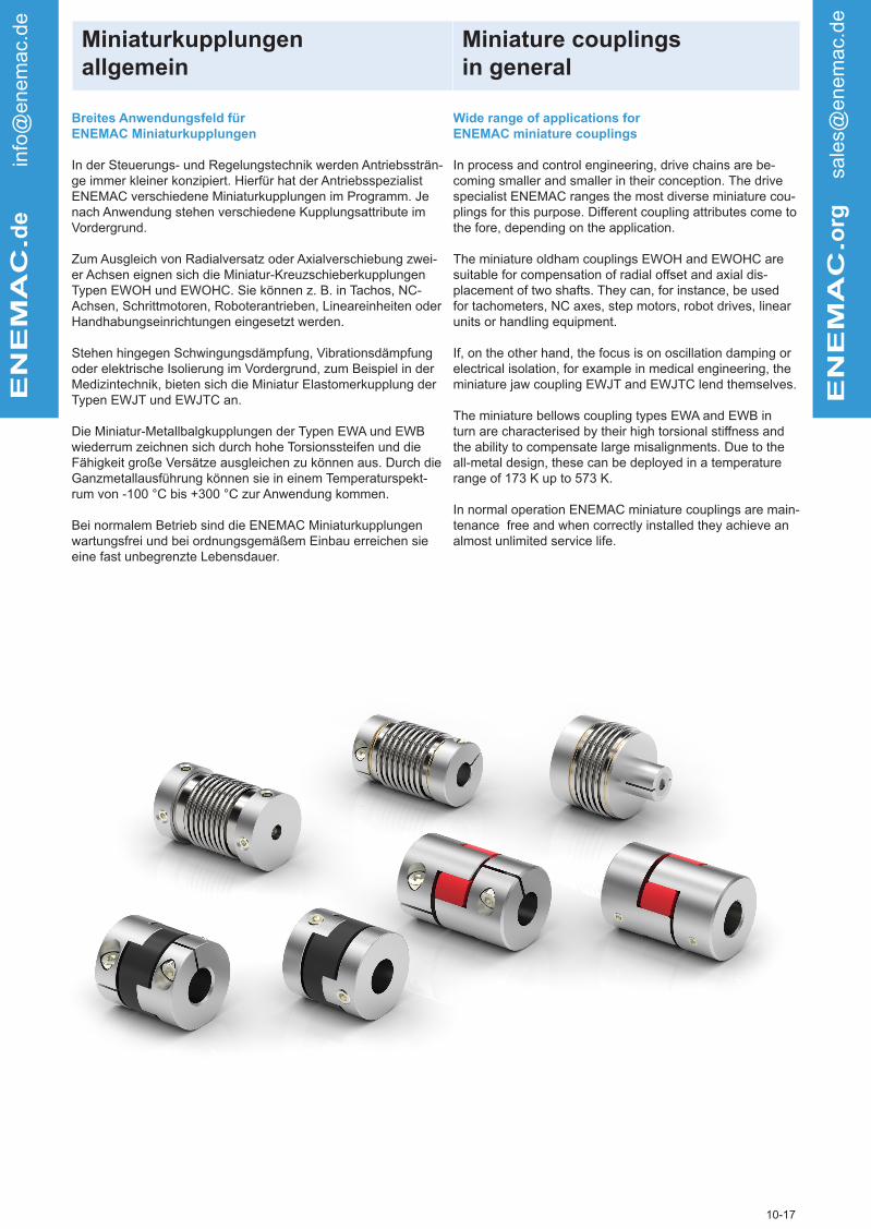
Miniaturkupplungen
allgemein
Miniature couplings
in general
ENEMAC.d
e in
fo@
enem
ac.d
e
ENEMAC.o
rg
sale
s@
enem
ac.d
e
Breites Anwendungsfeld für ENEMAC Miniaturkupplungen
In der Steuerungs- und Regelungstechnik werden Antriebssträn-
ge immer kleiner konzipiert. Hierfür hat der Antriebsspezialist
ENEMAC verschiedene Miniaturkupplungen im Programm. Je
nach Anwendung stehen verschiedene Kupplungsattribute im
Vordergrund.
Zum Ausgleich von Radialversatz oder Axialverschiebung zwei-
er Achsen eignen sich die Miniatur-Kreuzschieberkupplungen
Typen EWOH und EWOHC. Sie können z. B. in Tachos, NC-
Achsen, Schrittmotoren, Roboterantrieben, Lineareinheiten oder
Handhabungseinrichtungen eingesetzt werden.
Stehen hingegen Schwingungsdämpfung, Vibrationsdämpfung
oder elektrische Isolierung im Vordergrund, zum Beispiel in der
Medizintechnik, bieten sich die Miniatur Elastomerkupplung der
Typen EWJT und EWJTC an.
Die Miniatur-Metallbalgkupplungen der Typen EWA und EWB
wiederrum zeichnen sich durch hohe Torsionssteifen und die
Fähigkeit große Versätze ausgleichen zu können aus. Durch die
Ganzmetallausführung können sie in einem Temperaturspekt-
rum von -100 °C bis +300 °C zur Anwendung kommen.
Bei normalem Betrieb sind die ENEMAC Miniaturkupplungen
wartungsfrei und bei ordnungsgemäßem Einbau erreichen sie
eine fast unbegrenzte Lebensdauer.
Wide range of applications for ENEMAC miniature couplings
In process and control engineering, drive chains are be-
coming smaller and smaller in their conception. The drive
specialist ENEMAC ranges the most diverse miniature cou-
plings for this purpose. Different coupling attributes come to
the fore, depending on the application.
The miniature oldham couplings EWOH and EWOHC are
suitable for compensation of radial offset and axial dis-
placement of two shafts. They can, for instance, be used
for tachometers, NC axes, step motors, robot drives, linear
units or handling equipment.
If, on the other hand, the focus is on oscillation damping or
electrical isolation, for example in medical engineering, the
miniature jaw coupling EWJT and EWJTC lend themselves.
The miniature bellows coupling types EWA and EWB in
turn are characterised by their high torsional stiffness and
the ability to compensate large misalignments. Due to the
all-metal design, these can be deployed in a temperature
range of 173 K up to 573 K.
In normal operation ENEMAC miniature couplings are main-
tenance free and when correctly installed they achieve an
almost unlimited service life.
10-17

Miniatur-Metallbalgkupplung EWA Miniature metal bellows coupling
Technische Daten / technical data:
• Standardversion mit radialer Klemmnabe • standard-version with radial clamping hub
Abmessungen nach / dimensions acc. to DIN ISO 2768 cH:
EN
EM
AC
.de in
fo@
enem
ac.d
e
EN
EM
AC
.org
sale
s@
enem
ac.d
e
28-17
EWA 0,4 0,9 2 4 7 8 12
Nennmoment
nominal torque[Nm] 0,4 0,9 2 4 7 8 12
Trägheitsmoment
moment of inertia[10-3kgm2] 0,3 0,4 3,0 3,0 14 26 30
Torsionssteife
torsional stiffness [Nm/arcmin] 50 90 230 460 1100 1350 2050
max. Drehzahl
max.speed[min-1] 20.000 20.000 12.000 12.000 12.000 12.000 12.000
max. Wellenversatz axial ± [mm] 0,35 0,3 0,5 0,4 0,6 0,8 0,7
max. shaft displacement lateral [mm] 0,2 0,2 0,2 0,2 0,25 0,30 0,25
Federsteife axial[N/mm]
10 21 15 35 45 16 40
spring rate lateral 15 26 15 65 60 24 70
Masse ca.
weight approx.[g] 10 12 30 40 80 130 140
Anziehmoment d. Schrauben
tightening torque of screws[Nm] 1 1 2 2 4 8 8
Werkstoff:Balg: Edelstahl
Naben: hochfestes Aluminium
Schrauben: ISO 4762 vernickelt
EWA 0,4 0,9 2 4 7 8 12
Øa [mm] 16,5 16,5 24,5 (27,5) 24,5 (27,5) 34 40 (44,5) 40 (44,5)
b [mm] 9 9 13 13 14 16,5 16,5
c [mm] 4,6 4,6 7,5 (9,6) 7,5 (9,6) 11 13 (15,5) 13 (15,5)
f M2,5 M2,5 M3 M3 M4 M5 M5
h [mm] 3,3 3,3 4,4 4,4 5 6 6
L ±0,5 [mm] 30 31,5 42 43,5 57 60 62
Ø D1/2 min. [mm] 3 3 3 5 6 6 6
Ø D1/2 max. [mm] 6,35 6,35 10 (14) 10 (14) 17 19 (24) 19 (24)
Temperaturbereich: -100 °C bis 300 °C
Optional können Baugrößen 2 bis 12 mit montagefreundlicher
Klemm-nabe geliefert werden.
temperature range: 173 K up to 573 K
Sizes 2 to 12 are available with easy assembly clamping
system on request.
Bestellbeispiel / ordering example: EWA 0,9 - D1 = 4 H7 - D2 = 5 H7
f - ISO 4762
f - ISO 4762
EWA Ø3 Ø4 Ø5 Ø6 Ø6,35 Ø8 Ø9,53 Ø10 Ø12 Ø15 Ø16 Ø19
0,4 / 0,9 • • • • •
2 / 4 • • • • • • •
7 • • • • • • • •
8 / 12 • • • • • • • • •
Standard-Fertigbohrungen / stock bores D1/D2 (G7)
material:bellows: stainless steel
hubs: high tensile aluminium
screws: ISO 4762 nickel plated

Miniatur-Metallbalgkupplung EWB Miniature metal bellows coupling
Technische Daten / technical data:
• kurze Baulänge mit radialer Klemmnabe • short version with radial clamping hub
Abmessungen nach / dimensions acc. to DIN ISO 2768 cH:
ENEMAC.d
e in
fo@
enem
ac.d
e
ENEMAC.o
rg
sale
s@
enem
ac.d
e
10-17
EWB 2 5 7 8 12
Nennmoment
nominal torque[Nm] 2 5 7 8 12
Trägheitsmoment
moment of inertia[10-3kgm2] 2,5 2,8 12 25 28
Torsionssteife
torsional stiffness[Nm/arcmin] 400 800 1700 2100 2600
max. Drehzahl
max.speed[min-1] 12.000 12.000 12.000 12.000 12.000
max. Wellenversatz axial ± [mm] 0,3 0,3 0,4 0,5 0,4
max. shaft displacement lateral [mm] 0,1 0,1 0,15 0,15 0,15
Federsteife axial[N/mm]
32 70 70 20 45
spring rate lateral 100 400 220 90 190
Masse ca.
weight approx.[g] 30 40 80 125 130
Anziehmoment d. Schrauben
tightening torque of screws[Nm] 2 2 4 8 8
Werkstoff:Balg: Edelstahl
Naben: hochfestes Aluminium
Schrauben: ISO 4762 vernickelt
EWB 2 5 7 8 12
Øa [mm] 24,5 (27,5) 24,5 (27,5) 34 40 (44,5) 40 (44,5)
b [mm] 13 13 14 16,5 16,5
c [mm] 7,5 (9,6) 7,5 (9,6) 11 13 (15,5) 13 (15,5)
f M3 M3 M4 M5 M5
h [mm] 4,4 4,4 5 6 6
L ±0,5 [mm] 35 36 47 51 51
Ø D1/2 min. [mm] 3 6 6 6 6
Ø D1/2 max. [mm] 10 (14) 10 (14) 17 19 (24) 19 (24)
Temperaturbereich: -100 °C bis 300 °C
Optional können alle Baugrößen mit montagefreundlicher Klemm-
nabe geliefert werden.
temperature range: 173 K up to 573 K
All sizes are available with easy assembly clamping system, on
request.
Bestellbeispiel / ordering example: EWB 5 - D1 = 4 H7 - D2 = 12 H7
material:bellows: stainless steel
hubs: high tensile aluminium
screws: ISO 4762 nickel plated
EWB Ø4 Ø5 Ø6 Ø6,35 Ø8 Ø9,53 Ø10 Ø12 Ø15 Ø16 Ø19 Ø24
2 / 5 • • • • • • •
7 • • • • • • • •
8 / 12 • • • • • • • • •
Standard-Fertigbohrungen / stock bores D1/D2 (G7)
f - ISO 4762

Miniatur-Metallbalgkupplung EWKA Miniature metal bellows coupling
Technische Daten / technical data:
• kurze Baulänge mit radialer Klemmnabe • short version with radial clamping hub
Abmessungen nach / dimensions acc. to DIN ISO 2768 cH:
ENEMAC.d
e in
fo@
enem
ac.d
e
ENEMAC.o
rg
sale
s@
enem
ac.d
e
7-17
EWKA 0,4 0,9 2 4 6 8
Nennmoment
nominal torque[Nm] 0,4 0,9 2 4 6 8
Trägheitsmoment
moment of inertia[10-3kgm2] 0,19 0,19 2,9 3,2 16 28
Torsionssteife
torsional stiffness[Nm/arcmin] 50 90 230 460 1100 1300
max. Drehzahl
max.speed[min-1] 20.000 20.000 12.000 12.000 12.000 12.000
max. Wellenversatz axial ± [mm] 0,2 0,2 0,2 0,2 0,25 0,3
max. shaft displacement lateral [mm] 0,1 0,1 0,1 0,1 0,25 0,25
Federsteife axial[N/mm]
10 21 15 35 45 16
spring rate lateral 15 26 15 65 60 24
Masse ca.
weight approx.[g] 8 10 32 37 85 120
Anziehmoment d. Schrauben
tightening torque of screws[Nm] 1 1 4 4 8 10
Werkstoff:Balg: Edelstahl
Naben: hochfestes Aluminium
Schrauben: ISO 4029 vernickelt
EWKA 0,4 0,9 2 4 6 8
Øa [mm] 16 16 25 25 35 41
b [mm] 7 7 11 11 12,5 14
f 2 x M3 2 x M3 2 x M4 2 x M4 2 x M5 2 x M6
h [mm] 2,3 2,3 3,5 3,5 4,3 5
L ±0,5 [mm] 26 27,5 38 39,5 54 54,5
Ø D1/2 min. [mm] 3 3 5 5 6 6
Ø D1/2 max. [mm] 8 8 15 15 20 26
Temperaturbereich: -20 °C bis 90 °C
Optional können alle Baugrößen mit montagefreundlicher Klemm-
nabe geliefert werden.
Weitere Bohrungsdurchmesser auf Anfrage. Zur leichteren Demon-
tage empfehlen wir, die Welle mit Planflächen für Gewindestifte zu versehen.
temperature range: 253 K up to 363 K
All sizes are available with easy assembly clamping system on
request.
Further boresizes are available on request. For an easier
demounting we recommend plane surfaces for set screws on
the shaft.
Bestellbeispiel / ordering example: EWKA 2 - D1 = 6 H7 - D2 = 8 H7
EWKA Ø3 Ø4 Ø5 Ø6 Ø6,35 Ø8 Ø9,53 Ø10 Ø12 Ø15 Ø16 Ø19 Ø24
0,4 / 0,9 • • • • • •
2 / 4 • • • • • • • •
6 • • • • • •
8 • • • • • • • •
Standard-Fertigbohrungen / stock bores D1/D2 (G7)
f - ISO 4029
material:bellows: stainless steel
hubs: high tensile aluminium
screws: ISO 4029 nickel plated

Miniatur-Elastomerkupplung EWJT/EWJTC Miniature jaw coupling
Technische Daten / technical data:
• EWJTC: Standardversion mit radialer Klemmnabe• EWJT: kostengünstige Version mit Gewindestift• steckbar, schwingungsdämpfend
• EWJT: cost-effective version with set screws• EWJTC: standard version with radial clamping hub• pluggable, oscillation dampening
Abmessungen nach / dimensions acc. to DIN ISO 2768 cH:
ENEMAC.d
e in
fo@
enem
ac.d
e
ENEMAC.o
rg
sale
s@
enem
ac.d
e
10-17
EWJT / EWJTC 14-B 20-B 30-B 14-R 20-R 30-R
Nennmoment
nominal torque[Nm] 0,7 1,8 4 2 5 12,5
Trägheitsmoment
moment of inertia
EWJT[10-3kgm2]
0,21 1 5,9 0,21 1 5,9
EWJTC 0,16 1,1 6,2 0,16 1,1 6,2
Torsionssteife
torsional stiffness[Nm/arcmin] 3 5 13 7 16 38
max. Drehzahl
max.speed
EWJT[min-1]
27.000 20.000 13.000 27.000 20.000 13.000
EWJTC 11.000 7.500 5.000 11.000 7.500 5.000
max. Wellenversatz axial ±[mm]
0,6 0,8 1 0,6 0,8 1
max. shaft displacement lateral 0,15 0,2 0,2 0,1 0,1 0,1
Masse ca.
weight approx.[g] 7 18 48 7 18 48
Anziehmoment d. Schrauben f
tightening torque of screws i[Nm]
0,7
0,5
0,7
1
1,7
2,5
0,7
0,5
0,7
1
1,7
2,5
Werkstoff:Naben: Aluminium
Elastomerstern: Polyurethan B (80-Sh-A) blau; R (98-Sh-A) rot
EWJT / EWJTC 14-B 20-B 30-B 14-R 20-R 30-R
Øa [mm] 14 20 30 14 20 30
c [mm] 4 6,5 10 4 6,5 10
e [mm] 7 10 11 7 10 11
g [mm] 8 10 13 8 10 13
h [mm] 3,5 5 5,5 3,5 5 5,5
L ±0,5 [mm] 22 30 35 22 30 35
f [mm] 2 x M3 2 x M3 2 x M4 2 x M3 2 x M3 2 x M4
i [mm] M2 M2,5 M4 M2 M2,5 M4
Temperaturbereich: -20°C bis 70 °C
Temperaturkorrektur für Nennmoment TN
-20 °C bis + 30 °C + 50 °C + 70 °C
100 % 75 % 60 %
temperature range: 253 K up to 343 K
temperature correction for nominal torques TN
253 K up to 303 K 323 K 343 K
100 % 75 % 60 %
Bestellbeispiel / ordering example: EWJT 30-B - D1 = 8 H7 - D2 = 12 H7
material:hubs: aluminium
insert: polyurethane B (80-Sh-A) blue; R (98-Sh-A) red
EWJT / EWJTC Ø3 Ø4 Ø5 Ø6 Ø6,35 Ø8 Ø9,53 Ø10 Ø12 Ø14
14 • ʘ • ʘ • ʘ •
20 ʘ • ʘ • ʘ • ʘ • ʘ • •
30 • ʘ • ʘ • ʘ •ʘ •
Standard-Fertigbohrungen / stock bores D1/D2 (G7) •EWJT / ʘ EWJTC
EWJT EWJTC
f - ISO 4029
i - ISO 4762

Miniatur-Elastomerkupplung EWOH/EWOHC Miniature jaw coupling
Technische Daten / technical data:
• Ausgleich von großem Radialversatz - steckbar
• EWOHC: Standardversion mit radialer Klemmnabe
• EWOH: kostengünstige Version mit Gewindestiften
• compensation of radial shaft displacement, pluggable
• EWOHC: standard version with radial clamping hub
• EWOH: cost-effective version with set screws
Abmessungen nach / dimensions acc. to DIN ISO 2768 cH:
ENEMAC.d
e in
fo@
enem
ac.d
e
ENEMAC.o
rg
sale
s@
enem
ac.d
e
10-17
EWOH/EWOHC 16 20 25 32 43
Nennmoment
nominal torque[Nm] 1 1,5 2,5 7 15
Trägheitsmoment
moment of inertia
EWOH[10-3kgm2]
0,24 0,81 1,8 6,7 39
EWOHC 0,32 0,82 2,6 8,3 20
Torsionssteife
torsional stiffness[10-3Nm/arcmin] 19 35 58 180 340
max. Drehzahl
max.speed[min-1] 8.000 7.000 6.000 4.800 4.000
max. Wellenversatz radial ± [mm] 1 1,5 2 2,5 3
max. shaft displacement angular [°] 2 2 2 2 2
Masse ca.
weight approx.
EWOH[g]
7 14 20 48 160
EWOHC 10 16 34 80 160
Anziehmoment d. Schrauben f
tightening torque of screws i[Nm]
1
1
1,7
1
1,7
1,5
4
2,5
4
5
Werkstoff:Naben: Aluminium eloxiert
Elastomerstern: Polyacetal
EWOH/EWOHC 16 20 25 32 43
Øa [mm] 16 20 25 32 43
bEWOH
[mm]8 9 11,5 14,5 24
EWOHC 9,5 10 12 16 21,5
c [mm] 5 6,5 8 11 15
hEWOH
[mm]2,3 3,3 3 4 7
EWOHC 3 3 4 5 7
L EWOH
[mm]18 20 25,5 32 52
EWOHC 21 22,5 26,5 35 47
f M3 M4 2 x M4 2 x M5 2 x M5
i M2,6 M2,6 M3 M4 M5
Temperaturbereich: -20 °C bis 70 °C
Temperaturkorrektur für Nennmoment TN
-20 °C bis + 30 °C + 40 °C + 60 °C + 100 °C
100 % 80 % 60 % 50 %
temperature range: 253 K up to 373 K
temperature correction for nominal torques TN
253 K up to 303 K 313 K 333 K 373 K
100 % 80 % 60 % 50 %
Bestellbeispiel / ordering example: EWOH 25 - D1 = 8 H7 - D2 = 10 H7
material:hubs: aluminium alloy
insert: polyacetal
EWOH/EWOHC Ø3 Ø4 Ø5 Ø6 Ø6,35 Ø8 Ø9,53 Ø10 Ø12 Ø14 Ø15 Ø16 Ø19
16 • • • •
20 • • • • •
25 • • • • • •
32 • • • • • • • •
43 • • • • • • • • • •
Standard-Fertigbohrungen / stock bores D1/D2 (H8)
h b
L
L
bh
OD
2
OD
1O
D1
OD
2
i - DIN 912
f - DIN 916
c
Oa
Oa
EWOH EWOHC
f - ISO 4029
i - ISO 4762

Discs
The key components of this torsionally rigid coupling are the
disc packs, which consist of a series of stainless steel discs
(AIS 304-C) connected to steel bushes. This disc pack is con-
nected to the hub flange by steel bolts (Q10.9) and the corres-
ponding locknuts.
There are the following disc packs:
A) Continuous washers for 6 screws
(Coupling sizes 60-1700)B) Section disc pack for 6 screws
(Coupling sizes 2600-12000)C) Section disc pack for 8 screws
(Coupling sizes 25000-65000)
EN
EM
AC
.org
sale
s@
enem
ac.d
e
EN
EM
AC
.de info
@enem
ac.d
e
4-18
Lamellenkupplung allgemein Disc couplings in general
Lamellenkupplungen wurden entwickelt für Anwendungen, bei
denen hohe Zuverlässigkeit, Präzision und ein optimales Gewicht-/
Leistungsverhältnis erforderlich ist. Sie sind ideal für Anwendungen
mit hoher Drehzahl und Leistung, bei niedriger Radialbelastung.
Einsatzmöglichkeiten
Die Einsatzmöglichkeiten der Lamellenkupplungen finden sich in den verschiedensten Industriezweigen, wie der Bau-, Plastikerzeu-
gung, Textil-, Verpackungsindustrie, metallverarbeitende Unterneh-
men, Förderer, Pumpen und Kräne.
WerkstoffausführungLamellenkupplungen bestehen aus drei Hauptkomponenten, den
beiden Stahl-Naben (UNI EN 10083/98) und dem Lamellenpaket aus rostfreiem Edelstahl (AISI 304 C), mit Stahlschrauben der Güte
10.9.
Alle Komponenten der EWZK und EWZL-Kupplungen werden sta-
tisch ausgewuchtet (DIN ISO 1940-1: 2003 Q6,3).
Zusätzlich besteht die Möglichkeit alle Einzelteile bzw. die montierte
Kupplung nach Anforderung statisch oder dynamisch zu wuchten.
Lamellen
Die entscheidenden Bauteile dieser torsionssteifen Kupplung sind
die Lamellenpakete, die aus einer Reihe von Edelstahlscheiben
(AIS 304-C) verbunden mit Stahlbuchsen bestehen. Dieses Lamel-
lenpaket ist mit dem Nabenflansch verbunden durch Stahlschrau-
ben (Q10.9) und den entsprechenden Sicherungsmuttern.
Es gibt folgende Lamellenpakete:
A) Durchgängige Ringscheiben für 6 Schrauben
(Kupplungsgrößen 60-1700)B) Sektionsscheibenpaket für 6 Schrauben
(Kupplungsgrößen 2600-12000)C) Sektionscheibenpaket für 8
Schrauben
(Kupplungsgrößen 25000-65000)
Leistungsmerkmale
• Ausgleich hoher Axial- und
Radialversätze
• hohe Torsionssteife
• hohe Drehmomentübertra-
gung, High-Speed Anwendungen
Berechnung
Für die Vorwahl der Größe der Kupplung können Sie die übliche
Formel verwenden:
Die Lamellenkupplungen EWZK und EWZL können kurzzeitig ein
2,5 faches Spitzenmoment (Tamax
) kompensieren. Liegt Tamax
über
dem 2,5-fachen Faktor des Nenndrehmomentes, MUSS die Kupp-
lung nach folgender Formel berechnet werden: TA
max
TK‘ [Nm] = 2,5
Das im Katalog für Lamellenkupplungen angegebene Nenndreh-
moment bezieht sich auf das statische Drehmoment, das zweimal
niedriger als das Nenndrehmoment ist, wobei der Betriebsfaktor
f = 1,5 ist. Wenn das statische Drehmoment des Motors zweimal höher als der Nennwert ist, sollte nach folgender Formel berechnet
9550 x P x K [kW]T
K [Nm] = n [min-1]
TK‘ > T
K
Tamax
TK [Nm] = 1,5
TK > T
K‘
TK
TK‘
Tamax
K
P
n
= tatsächliches nominales Nennmoment [Nm]
= theoretisches nominales Nennmoment [Nm]
= Spitzendrehmoment [Nm]
= Stoßfaktor
= Leistung [kW]
= Drehzahl [min-1]
Typ A Typ B Typ C
Disc couplings have been developed for applications with high
reliability, precision and an optimal weight / performance ratio
requirements. They are ideal for applications with high speed
and power, during low radial load.
typical applications
Application-fields of disc couplings can be found in a wide variety of industries, such as construction, plastics, textile,
packaging, metalworking companies, conveyors, pumps and
cranes.
Material version
Disc couplings consist of three main components, the two steel
hubs (UNI EN 10083/98) and the stainless steel disc pack (AISI 304 C), with grade 10.9 steel screws.
All components of the EWZK and EWZL couplings are statically
balanced (DIN ISO 1940-1: 2003 Q6,3).
In addition, it is possible to balance all individual parts or the
assembled coupling statically or dynamically as required.
Features
Compensation of high axial and
radial misalignments
high torsional rigidity
high torque transmission, high-
speed applications
Calculation
For the preselection of the size of the coupling you can use the
usual formula:
The disc couplings EWZK and EWZL can temporarily compen-
sate for a 2.5 times peak torque (Tamax
). If Tamax
is over 2.5 times
the rated torque, the coupling HAS TO be calculated according
to the following formula:
The rated torque given in the disc couplings catalog refers to
the static torque, which is twice lower than the rated torque,
with the service factor f = 1.5. If the static torque of the engine is twice higher than the nominal value, it should be calculated
according to the following formula:
9550 x P x K [kW]T
K [Nm] = n [min-1]
TAmax
TK‘ [Nm] = 2,5
TK‘ > T
K
Tamax
TK [Nm] = 1,5
TK > T
K‘
TK
TK‘
Tamax
K
P
n
= actual nominal rated torque[Nm]
= theoretical nominal nominal torque[Nm]
= peak torque [Nm]
= shock factor
= power [kW]
= speed [min-1]

EN
EM
AC
.de info
@enem
ac.d
e
EN
EM
AC
.org
sale
s@
enem
ac.d
e
4-18
Lamellenkupplung allgemein Disc couplings in general
EWZL Hinweise
Die Ausgangsbemessung im Katalog bezieht sich auf den normalen
Gebrauch ohne Stöße und mit Wellen, die gut auf die Umgebungs-
temperatur abgestimmt sind (-20 °C bis +250 °C). Der Wert des
Axialschubs (+/- 20%) steht im Verhältnis zur Axialbewegung.
(s. Abb. 1)
Die maximal zulässige Drehzahl wird durch mehrere
Faktoren beeinflusst:
1.) Umfangsgeschwindigkeit der Kupplung2.) Gewicht der Kupplung
3.) Länge des Zwischenrohrs
4.) Steifigkeit der Kupplung5.) Wuchtgüte
Für die meisten Anwendungen ist das dynamische Auswuchten
nicht erforderlich, in anderen Fällen bitte ENEMAC kontaktieren.
Montage
1.) Radial und axial möglichst genau ausrichten, um die maximale Absorption möglicher Achsverschiebungen und Lebensdauer der
Kupplung zu ermöglichen. (Abb. 2 und Abb. 3)
2.) Die Wellen müssen so montiert werden, dass ihre Endpunkte
zur Oberfläche der Kupplung rechtwinklig sind (die Länge des Zwischenrohrs mit zwei Scheibenpaketen sollte gleich dem Abstand
zwischen den beiden Wellen sein) (Abb. 4)
3.) Ziehen Sie die Schrauben mit einem Drehmomentschlüssel über
Kreuz an, bis Sie das im Katalog angegebene Anzugsdrehmoment
erreichen. Wir empfehlen nur die Mutter / Schraube, die nicht mit
dem Scheibenpaket in Berührung kommt, zu drehen, um ein Verdre-
hen der Lamellen zu verhindern.
4.) Zum Abschluss muss geprüft werden, ob die Scheibenpakete
perfekt senkrecht zur Wellenachse sind. Bei Bedarf Punkt 3 wieder-
holen.
Bei der Kupplungsversion mit Zwischenrohr (EWZL) kann der
Mittelteil der Kupplungen (Rohr) als ein zwischen zwei Federn
(Lamellenpaket) aufgehängtes Gewicht betrachtet werden. Um eine
Oszillation des Zwischenrohrs zu vermeiden wird empfohlen, den
Abstand zwischen den Flanschen der Naben im Vergleich zu den
Nennmaßen um 1,5 bis 2 mm zu erhöhen, um die natürliche axiale Frequenz zu verringern. Auf diese Weise werden die Lamellenpake-
te unter Spannung gehalten und die Möglichkeit der Zwischenrohr-
oszillation reduziert.
Hinweis: Bei Montage in senkrechter Position muss das Zwischen-
rohr unterstützt werden, um das Gewicht zu reduzieren.
Abb. 1 / fig. 1
Abb. 2 / fig. 2Abb. 3 / fig. 3 Abb. 4 / fig. 4
EWZL notes
The initial rating in the catalog refers to normal use without im-
pact and with shafts that are well tuned to the ambient tempe-
rature (253 K to 523K). The value of the axial thrust (+/- 20%) is
related to the axial movement. (see Fig. 1)
The maximum permissible speed is influenced by several factors:
1.) peripheral speed of the clutch2.) Weight of the clutch
3.) Length of the intermediate pipe
4.) stiffness of the coupling5.) Balancing quality
For most applications dynamic balancing is not required, in
other cases please contact ENEMAC.
Mounting
1.) 1.) Radial and axial align as accurately as possible to allow maximum absorption of possible axial displacements and life of
the coupling. (Fig. 2 and Fig. 3)
2.) The shafts have to be mounted with their end points perpen-
dicular to the surface of the coupling (the length of the interme-
diate pipe with two disc packs should be equal to the distance
between the two shafts) (Fig. 4)
3.) Using a torque wrench, tighten the screws diagonally until
you reach the tightening torque specified in the catalog. We recommend only turning the nut / screw that does not come into
contact with the disc pack to prevent the discs from twisting.
4.) Finally, it has to be checked whether the disc packs are
perfectly vertical to the shaft axis. If necessary, repeat point 3.
In case of coupling version with intermediate pipe (EWZL),
the middle part of the couplings (pipe) can be considered as a
suspended weight between two springs (disk pack). In order to
avoid oscillation of the intermediate pipe, it is recommended to
increase the distance between the flanges of the hubs by 1.5 to 2 mm compared to the nominal dimensions in order to reduce
the natural axial frequency. In this way, the disk packs are kept
under tension and reduces the possibility of intermediate-pipe-
oscillation.
Note: When mounting in vertical position, the intermediate pipe
has to be supported to reduce the weight.

24-17
Lamellenkupplung EWZL• Ausgleich hoher Axial- und Radialversätze• mit verschiedenen Wellenanbindungen lieferbar• hohe Torsionssteife
• mit variabler Zwischenrohrlänge erhältlich
• compensates high axial/radial misalignments • available for various shaft connections• hightorsionalstiffness• available with variable intermediate pipe length
Nenn-moment
max. Dreh-zahl
Trägheits-moment
Masse ØD1/D2 ØDK1/D
K2
Torsions-steife
Wellenversatz
EWZL nominal torque
max. speedmoment of
inertiamass ØD1/D2 ØD
K1/D
K2
torsional stiffness misalignment
[Nm] [min-1] 10-3[kgm2] [kg] max [mm] max [mm] [Nm/arcmin]angular
[°]
axial
[mm]
radial
[mm]
60 60 14.500 0,83 1,7 32 25 12 1,5 1,4 0,70
100 100 14.200 0,92 1,8 32 25 15 1,5 1,6 0,80
150 150 12.500 2,86 3,5 38 30 21 1,5 1,8 0,80
300 300 10.200 7,40 5,8 45 35 54 1,5 2,4 0,95
700 700 8.500 16,60 9,4 52 45 123 1,5 2,8 1,20
1100 1.100 7.000 28,50 15,2 65 55 234 1,5 3,2 1,45
1700 1.700 6.300 63,58 23 80 70 297 1,5 4,0 1,55
2600 2.600 5.500 128,16 34 90 80 464 1,5 4,4 1,55
4000 4.000 5.000 229,27 47 95 80 1.163 1,5 4,8 2,15
7000 7.000 4.500 445,98 61 110 - 1.511 1,5 5,0 2,15
10000 10.000 3.800 799,95 96 120 - 1.947 1,5 5,2 2,4
12000 12.000 3.600 1228,23 132 138 - 1.964 1,5 5,8 2,4
25000 25.000 3.200 1971,20 173 155 - 4.627 1 5,8 1,3
35000 35.000 3000 3062,40 208 175 - 6.344 1 6,2 1,7
50000 50.000 2700 4894,20 280 190 - 7.857 1 6,8 1,8
65000 65.000 2500 6932,50 350 205 - 9.312 1 7,7 1,9
E
NE
MA
C.d
e
info
@enem
ac.d
e
EWZL Øa Øb e f g h
i / Anziehmoment
i / tightening Torque[Nm]
k L
60 78 45 22 M6 50 10 M5 10,5 7,5 123
100 80 45 24 M6 50 10 M5 10,5 8 138
150 92 53 24 M6 50 10 M6 17 8 150
300 112 64 30 M8 59 15 M8 43 10 171
700 136 76 36 M10 75 15 M8 43 12 211
1100 162 92 39 M12 95 20 M10 84 13 253
1700 182 112 42 M12 102 20 M12 145 14 290
2600 206 128 45 M14 101 20 M12 145 15 315
4000 226 133 66 M18 136 20 M16 360 22 380
7000 252 155 75 M20 130 25 - - 25 400
10000 296 170 96 M27 144 25 - - 32 440
12000 318 195 96 M27 136 30 - - 32 480
25000 352 218 102 M27 172 40 - - 34 550
35000 386 252 111 M30 226 40 - - 37 650
50000 426 272 111 M33 236 45 - - 37 690
65000 456 292 126 M36 246 45 - - 42 740
Disc Clutch EWZL
Passfedernut nach DIN 6885/1
keyway according DIN 6885/1
Werkstoff:Stahl 1.0503
Lamellen: Edelstahl
material: steel C45
disc pack: stainless steel
g auf Anfrage bis max. 3 m
g on request up to 3 m
Ausführung mit radialen Klemmnaben
version with clamping hubs
EN
EM
AC
.org
sale
s@
enem
ac.d
e
Bestellbeispiel EWZL 60 D1 = 32 H7; D2 = 32 H7ordering example EWZL 60 D1 = 25 H7; D2 = 25 H7 m. Klemmnaben/w. clamping hubs
Temperaturbereich: -20 °C bis +150°C
Sondervariante für -20 °C bis +250 °C
temperature range: 253 K up to 423 K
special variant for 253 K up to 523 K

Lamellenkupplung EWZK
• Ausgleich hoher Axialversätze• mit verschiedenen Wellenanbindungen lieferbar• hohe Torsionssteife • hohe Drehmomentübertragung möglich
• compensation of high axial misalignments • available with various shaft connections • hightorsionalstiffness• high torques transferable
Nenn-
moment
max. Dreh-
zahl
Trägheits-
momentMasse ØD1/D2 ØD
K1/D
K2
Torsions-
steife
Wellenver-
satz
EWZKnominal
torquemax. speed
moment of
inertiamass ØD1/D2 ØD
K1/D
K2
torsional
stiffness misalignment
[Nm] [min-1] 10-3[kgm2] [kg] max [mm] max [mm] [Nm/arcmin]angular
[°]
axial
[mm]
60 60 14.500 0,58 1,6 32 25 23 0,75 0,7
100 100 14.200 0,67 1,3 32 25 34 0,75 0,8
150 150 12.500 1,93 2,4 38 30 45 0,75 0,9
300 300 10.200 3,86 3,9 45 35 121 0,75 1,2
700 700 8.500 8,69 6,3 52 45 282 0,75 1,4
1100 1.100 7.000 10,09 10,4 65 55 537 0,75 1,6
1700 1.700 6.300 36,48 15,6 80 70 652 0,75 2,00
2600 2.600 5.500 77,35 24,8 90 80 1021 0,75 2,2
4000 4.000 5.000 134,03 33 95 80 2615 0,75 2,4
7000 7.000 4.500 254,45 42 110 - 3474 0,75 2,5
10000 10.000 3.800 450,19 67 120 - 4573 0,75 2,6
12000 12.000 3.600 716,54 94 138 - 4515 0,75 2,9
25000 25.000 3.200 1223,40 130 140 - 10966 0,50 2,9
35000 35.000 3.000 1944,10 160 175 - 14981 0,50 3,1
50000 50.000 2.700 3109,50 210 190 - 18704 0,50 3,4
65000 65.000 2.500 4379,20 270 205 - 20304 0,50 3,8
EWZK Øa Øb e f h
i / Anziehmoment
i / tigthening i
[Nm]
k L
60 78 45 22 M6 10 M5 10,5 7,5 65,5
100 80 45 24 M6 10 M5 10,5 8 80
150 92 53 24 M6 10 M6 17 8 92
300 112 64 30 M8 15 M8 43 10 102
700 136 76 36 M10 15 M8 43 12 124
1100 162 92 39 M12 20 M10 84 13 145
1700 182 112 42 M12 20 M12 145 14 174
2600 206 128 45 M14 20 M12 145 15 199
4000 226 133 66 M18 20 M16 360 22 222
7000 252 155 75 M20 25 - - 25 245
10000 296 170 96 M27 25 - - 32 272
12000 318 195 96 M27 30 - - 32 312
25000 352 218 102 M27 40 - - 34 344
35000 386 252 111 M30 40 - - 37 387
50.000 426 272 111 M33 45 - - 37 417
65.000 456 292 126 M36 45 - 42 452
Bestellbeispiel EWZK 60 D1 = 32 H7; D2 = 32 H7
ordering example EWZK 60 D1 = 25 H7; D2 = 25 H7 m. Klemmnaben/w. clamping hubs
Disc Clutch EWZK
Werkstoff:Stahl 1.0503
Lamellen: Edelstahl
material: steel C45
disc pack: stainless steel
Passfedernut nach DIN 6885/1
keyway according DIN 6885/1
Ausführung mit radialen Klemmnaben
version with clamping hubs
EN
EM
AC
.de in
fo@
enem
ac.d
e
EN
EM
AC
.org
sale
s@
enem
ac.d
e
24-17
Temperaturbereich: -20 °C bis +150°C
Sondervariante für -20 °C bis +250 °C
temperature range: 253 K up to 423 K
special variant for 253 K up to 523 K

23-16
ENEMAC.o
rg
sale
s@
ene
mac.d
e
ENEMAC.d
e info
@enem
ac.d
e
Weitere Produkte / Further products:
Sicherheitskupplungen
Torque limiters
Spannelemente
Clamping elements
ENEMAC GmbH
Telefon: +49 (0) 6022 7107 - 0
Daimler Ring 42
Fax: +49 (0) 6022 22237
GERMANY


![EWA 10 EWA 12 EWA 14 EWA 16 - Lock · 2 90000.0002.3985 / 2012.11 mm[inch] EWA 10 EWA 12 OBJ_BUCH-0000000007-004.book Page 2 Tuesday, November 6, 2012 4:46 PM](https://static.fdocuments.in/doc/165x107/5f0238117e708231d4032a85/ewa-10-ewa-12-ewa-14-ewa-16-lock-2-9000000023985-201211-mminch-ewa-10-ewa.jpg)


![EWA 10 EWA 12 EWA 14 EWA 16 - Lock · 2017. 6. 6. · 2 90000.0002.3985 / 2012.11 mm[inch] EWA 10 EWA 12 OBJ_BUCH-0000000007-004.book Page 2 Tuesday, November 6, 2012 4:46 PM](https://static.fdocuments.in/doc/165x107/600f29001f27fe72783edc42/ewa-10-ewa-12-ewa-14-ewa-16-lock-2017-6-6-2-9000000023985-201211-mminch.jpg)