Water Cooled Centrifugal Chiller HTS/HTC - Daikin - Water... · chiller depends largely on an easy...
16
MANAGEMENT SYSTEM CNAS C002-M MANAGEMENT SYSTEM CNAS C002-M MANAGEMENT SYSTEM CNAS C002-M TESTING CNAS L7576 Cooling capacity: 300-2600 Tons (1055.0kW-9142.0kW) HFC-134a Refrigerant Water Cooled Centrifugal Chiller HTS/HTC
Transcript of Water Cooled Centrifugal Chiller HTS/HTC - Daikin - Water... · chiller depends largely on an easy...

MANAGEMENT SYSTEM
CNAS C002-M
MANAGEMENT SYSTEM
CNAS C002-M
MANAGEMENT SYSTEM
CNAS C002-M
TESTING
CNAS L7576
Cooling capacity: 300-2600 Tons (1055.0kW-9142.0kW)HFC-134a Refrigerant
Water Cooled Centrifugal Chiller
HTS/HTC

Contents
01Introduction
Technology Features 02
Technical Data 07
Dimensions 09
12Options /Startup Range
01Nomenclature
13Application Standard / Water Quality Management
Dual Compressor Centrifugal Chillers 05
Control Features 06

World-Class Design Leader
Introduction
Nomenclature
01
HT S 087M AU 49-F E3012
Hermetic Turbo(Centrifugal chiller)
S-Single compressorC-Dual compressors counterflow
Gear Ratio
Condenser Code
Evaporator Code
Motor Code
2
Impeller code
Evaporator Tube Count Code
Number of Passes(1,2)
Condenser Tube Count Code
Number of Passes(1,2)
Condenser Tube Type Code
Evaporator Tube Type Code
Daikin, as the world leading air conditioning
company, has earned a worldwid reputation
for providing high quality products and
expertise to meet variable requirements from
different customers. Our customers benefit
from maximum energy saving, lower
installation and operation cost, quiet
operation, superior indoor air quality. Daikin
has been dedicating to the ongoing
commitment of products development and
technology innovation and also offers
i n d u s t r i c a l - l e a d i n g a n d e x c e l l e n t
performance products as always.
- - - - - B - E - 2 - C3012 - D - L -
Power Supply: F: 380V/50HzG: 400V/50HzU: 380V/60HzR: 460V/60Hz

Technology Features
CompressorSemi-hermetic single stage compressor
Daikin centrifugal chillers have been designed with reliable and sustainable gear driveline system.
The precision-engineered gear driven design allows for lighter components, less vibration, and giving
ability to select gear ratios that will provide the optimum impeller speed for your application. Daikin gear
drive compressor has a series of top speed ratios that allow for selecting the maximum efficiency
impeller from full load to part load range.
02
Daikin's impeller design is only with larger compression coefficient and small pressure loss but also at
quite a low noise sound level.
The compressor cooling capacity is controlled by inlet guide vane installed at the entry of compressor to
offer required refrigerant quantity.
The advanced inlet guide vane produces linear refrigerant flow at high load condition. Pre-whirl the suck
gas refrigerant at part load to improve the compression efficiency. The simple and small discharge
volute design guide compressor gas directly entering the condenser ensuring the compressor efficiency.
Daikin semi-hermetic centrifugal chiller has benefited our customer by easy-to-maintenance as well as
eliminating additional cost of plant room ventilation system due to compressor motor is cooled by
refrigerant.
High Efficient Heat ExchangerEvaporator and condenser shall be shell-and-tube type, designed, constructed, tested and stamped
according to the requirement of GB code. The Shell-tube type vessel operating with refrigerant in shell
and water in tubes with 2 pass as standard. The smart vessel has optimized the compact structure to
greatly improve heat transfer and downsize the footprint as well. Replaceable enhanced copper tubes
are fabricated from integral finned copper and mechanically bonded to steel tube sheet for maximum
heat transfer.
Electronic Expansion ValveDaikin centrifugal chiller is equipped with a high-precision throttling device, which can be adjusted by
electronic expansion valve or electronic pilot valve plus main valve in response to different application.
The chiller controller is able to adjust precisely the electronic expansion valve opening to provide
adequate refrigerant flow by keeping monitoring the condenser liquid level.

03
Lubrication SystemA separately driven electric oil pump assembly supplies lubrication at controlled temperature and
pressure to all bearing surfaces and is the source of hydraulic pressure for the capacity control system.
The control system will not allow the compressor to start until oil pressure, at the proper temperature, is
established. It also allows the oil pump to operate after compressor shut down to provide lubrication
during coast-down. Lubricant from the pump is supplied to the compressor through a water-cooled,
brazed-plate heat exchanger and single or dual five-micron oil filters internal to compressor. All bearing
surfaces are pressure lubricated. Drive gears operate in a controlled lubricant mist atmosphere that
efficiently cools and lubricates them.
Lubricant is made available under pressure from the compressor oil filter to the unit capacity control
system and is used to position the inlet guide vanes in response to changes in leaving chiller water
temperature. If a power failure occurs, an emergency oil reservoir provides adequate lubrication flow
under pressure, and prevents damage that could occur during the coast-down period with the oil pump
stopped.
Since the Daikin chillers are positive pressure, there is no need to change the lubricant or filter on a
regular basis. As with any equipment of this type, an annual oil check is recommended to evaluate the
lubricant condition.
Excellent UnloadingDaikin pioneered use of movable discharge geometry to lower the surge point of centrifugal
compressors. The point which the compressor enters a stall or surge condition generally limits
compressor unloading. Chillers with a fixed discharge will experience or surge at low load.
Due to refrigerant re-entering the impeller, when in a stall condition, the refrigerant gas is unable to enter
Twin Relief ValvesThe spring loaded pressure twin relief valves, mounted on a transfer valve, are installed on the vessel
so that one relief valve can be shut off and removed for testing or replacement, leaving the other in
operation, only one of the two valves in operation.
the volute due to its low
velocity and remains
stalled in the impeller. In
a surge condition the
gas rapidly reverses
direction in the impeller
c a u s i n g e x c e s s i v e
vibrat ion and heat.
Daikin compressors
reduce the discharge
area as load decreases
to maintain gas velocity
and greatly reduce the
tendency to stall or
surge.
04
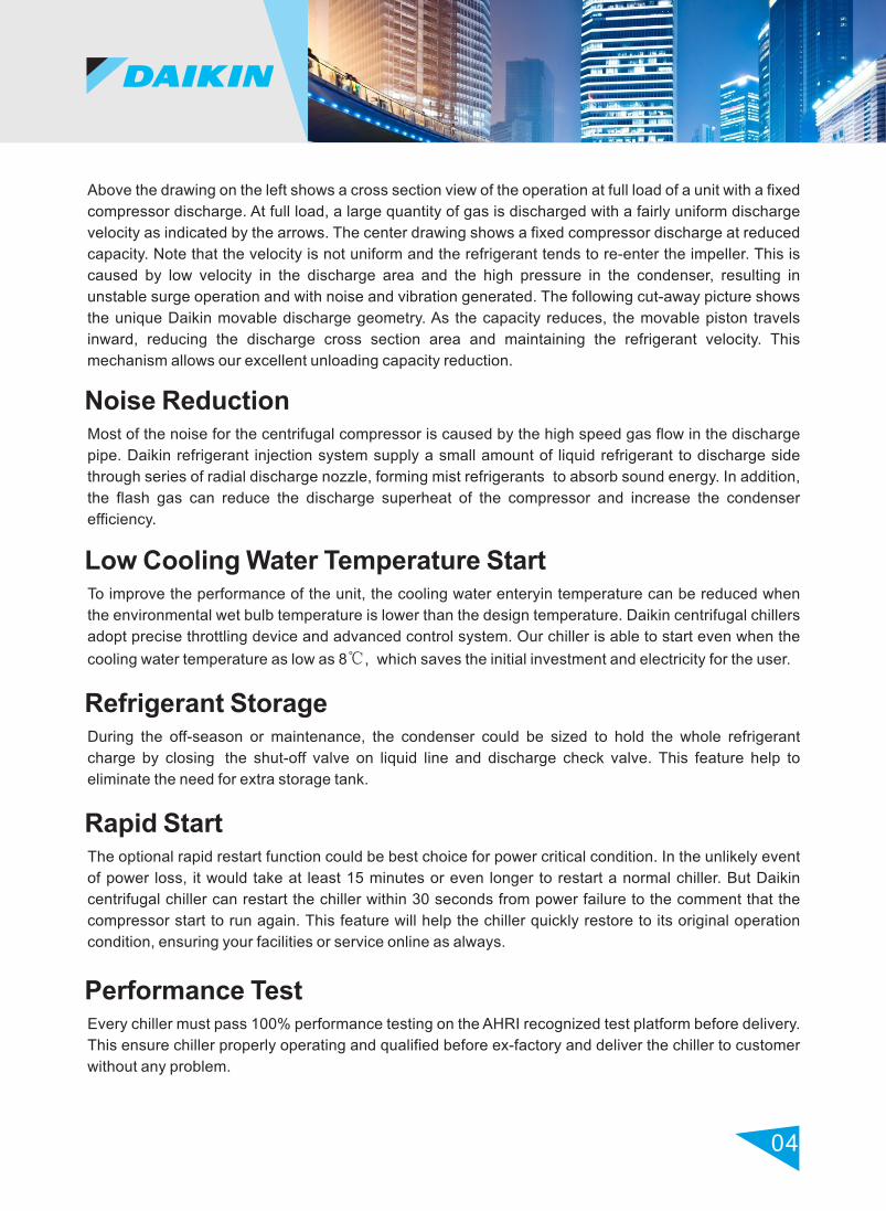
Above the drawing on the left shows a cross section view of the operation at full load of a unit with a fixed
compressor discharge. At full load, a large quantity of gas is discharged with a fairly uniform discharge
velocity as indicated by the arrows. The center drawing shows a fixed compressor discharge at reduced
capacity. Note that the velocity is not uniform and the refrigerant tends to re-enter the impeller. This is
caused by low velocity in the discharge area and the high pressure in the condenser, resulting in
unstable surge operation and with noise and vibration generated. The following cut-away picture shows
the unique Daikin movable discharge geometry. As the capacity reduces, the movable piston travels
inward, reducing the discharge cross section area and maintaining the refrigerant velocity. This
mechanism allows our excellent unloading capacity reduction.
Noise ReductionMost of the noise for the centrifugal compressor is caused by the high speed gas flow in the discharge
pipe. Daikin refrigerant injection system supply a small amount of liquid refrigerant to discharge side
through series of radial discharge nozzle, forming mist refrigerants to absorb sound energy. In addition,
the flash gas can reduce the discharge superheat of the compressor and increase the condenser
efficiency.
Low Cooling Water Temperature StartTo improve the performance of the unit, the cooling water enteryin temperature can be reduced when
the environmental wet bulb temperature is lower than the design temperature. Daikin centrifugal chillers
adopt precise throttling device and advanced control system. Our chiller is able to start even when the
cooling water temperature as low as 8℃, which saves the initial investment and electricity for the user.
Rapid StartThe optional rapid restart function could be best choice for power critical condition. In the unlikely event
of power loss, it would take at least 15 minutes or even longer to restart a normal chiller. But Daikin
centrifugal chiller can restart the chiller within 30 seconds from power failure to the comment that the
compressor start to run again. This feature will help the chiller quickly restore to its original operation
condition, ensuring your facilities or service online as always.
Refrigerant StorageDuring the off-season or maintenance, the condenser could be sized to hold the whole refrigerant
charge by closing the shut-off valve on liquid line and discharge check valve. This feature help to
eliminate the need for extra storage tank.
Performance TestEvery chiller must pass 100% performance testing on the AHRI recognized test platform before delivery.
This ensure chiller properly operating and qualified before ex-factory and deliver the chiller to customer
without any problem.

05
High efficiency and large capacity is required with series flow
Project requirements is lowest kW per ton performance at full load with high electrical demand
charges
Single pass counter flow series design, water pressure drop decrease to 40kPa, save pump energy
consumption by 30% compare to traditional unit
Dual Compressor Centrifugal Chillers
Dual Compressor Centrifugal Chillers
Daikin is the expert when it comes to dual centrifugal compressor technology, successfully building dual
compressor centrifugal chillers since 1971.
Use HTC Chillers When:
Figure2:Dual Circuit HTC Counter flow chillers.
These chillers have a separate refrigerant circuit for each compressor. They are available in single pass
only. BY reducing the lift on each compressor, they provide the high full load efficiency advantage of two
separate chillers arranged for counterflow operation in a single compact unit.
CHILLEDWATER OUT
CONDENSERWATER IN
CHILLEDWATER IN
CONDENSERWATER OUTCONDENSER
EVAPORATOR
CIRCUIT#2 CIRCUIT#1
CIRCUIT#2 CIRCUIT#1
06
Human Machine Interface Touch Screen
Proactive ControlBy constantly monitoring chiller status, the Micro Tech V controller will automatically take proactive
measures to relieve abnormal conditions or shut the unit down if a fault occurs. For example, if a
problem occurs in the cooling tower and discharge pressure starts to rise, the controller will
automatically hold the load point and activate an alarm signal. A further rise in pressure will initiate
compressor unloading in an effort to maintain the setpoint pressure. If the pressure continues to rise, the
unit will shut off at the cutout pressure setting.
The human machine interface touch screen (HMI) is the primary device by which commands and entries
into the control system are made. It also displays all controller data and information on a series of
graphic screen. A single HMI is used on both single and dual compressor units.
The HMI contains a USB disk that can be used for loading information to and from the control system.
There is a screen-saver programed into the system. The screen is reactivated by touching it anywhere.
Open Choices Benefits
Easy to integrated into your building
automatic system
Factory or filed installed communication
modules
Comprehensive point list for system
integration, equipment, monitoring and
alarm notification
Comprehensive data exchange
Protocol Options
BACnet MS/TP
BACnet/IP
BACNet Ethernet
Modbus RTU
LONWORKS
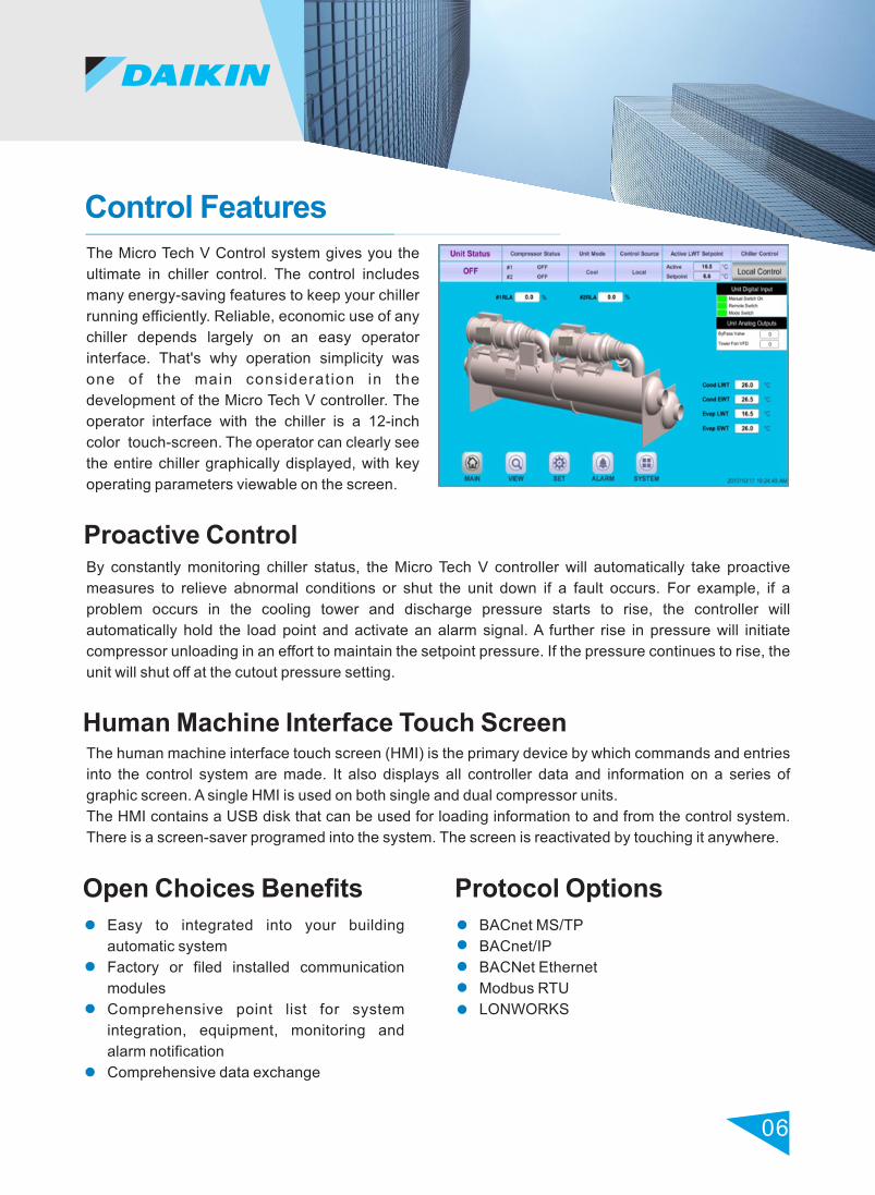
Control Features
The Micro Tech V Control system gives you the
ultimate in chiller control. The control includes
many energy-saving features to keep your chiller
running efficiently. Reliable, economic use of any
chiller depends largely on an easy operator
interface. That's why operation simplicity was
one of the main considerat ion in the
development of the Micro Tech V controller. The
operator interface with the chiller is a 12-inch
color touch-screen. The operator can clearly see
the entire chiller graphically displayed, with key
operating parameters viewable on the screen.

Technical Data
Model
Notes:1. Above chiller cooling capacity is based on AHRI standard condition :
2. Evap: EEWT 12.22°C,ELWT 6.67°C; Fouling factor 0.0176°C m / kW;2. Cond: CEWT 29.44°C, CLWT 34.61°C; Fouling factor0.0440°C m / kW;
2. Above chiller is recommended, please contact local sales for other specific models;
3. Standard:2 Pass evaporator and condenser;
4. Above data based on selection program . For specific project, please refer to the latest version.DST13.40
07
Cooling
capacity
Power
Consumption
COP
kW/ kW AA
Chiller
Weight
Operation
Weight
Kg Kg
HTS087MAU49F/E3612-CE-2/C3012-DL-2
HTS087MAU49F/E3009-CE-2/C2609-CL-2
HTS087MAU49F/E3612-BE-2/C3012-DL-2
HTS087MAU49F/E3009-BE-2/C2609-BL-2
HTS087MAU49F/E3612-BE-2/C3612-BL-2
HTS087MAT57F/E3609-BE-2/C3009-CL-2
HTS100MAZ59F/E3012-FK-2/C3012-JK-2
HTS100MAZ59F/E3012-EK-2/C3012-EK-2
HTS100MAY71F/E3312-FK-2/C3012-EK-2
HTS113MBE71F/E3312-QH-2/C3012-FK-2
HTS113MBE71F/E3312-QH-2/C3012-EK-2
HTS126LBHN0F/E3612-EK-2/C3012-EK-2
HTS126LBHN0F/E3612-FK-2/C3612-KK-2
HTS126MBHN0F/E3612-EK-2/C3612-JK-2
HTS126MBHN0F/E3612-EK-2/C3612-GK-2
HTS126MBHN1F/E3912-PH-2/C3612-FK-2
HTS Star-Delta/Solid-State (380V/3P~/50Hz)
Tons(kW) kW
Rated
Load
Flow RateL/s
Flow RateL/s
Pressure DropkPa
Pressure DropkPa
Evap. Cond.
500.0(1758)
500.0(1758)
550.0(1934)
550.0(1934)
600.0(2110)
600.0(2110)
700.0(2462)
700.0(2462)
760.0(2673)
800.0(2813)
850.0(2989)
950.0(3340)
950.0(3340)
1050(3692)
1100(3868)
1200(4220)
279.6
297.5
307.7
328.2
337.1
364.4
425.3
411.1
460.3
463.5
490.9
575.1
571.5
635.7
666.7
712.8
6.288
5.910
6.287
5.894
6.259
5.790
5.789
5.989
5.807
6.070
6.090
5.808
5.845
5.808
5.802
5.921
487
517
535
571
586
632
735
709
793
799
848
986
980
1095
1151
1237
75.45
75.45
83.01
83.01
90.56
90.56
105.7
105.7
114.7
120.7
128.3
143.4
143.4
158.5
166.0
181.1
42.3
73.8
37.3
68.7
43.7
33.4
91.4
72.7
55.0
76.1
84.5
48.2
57.9
57.7
62.8
76.0
93.80
94.67
103.3
104.3
112.8
114.1
132.7
132.0
144.1
150.8
160.2
180.4
180.3
199.6
209.2
227.7
50.2
58.8
59.3
56.2
22.3
45.5
99.3
65.8
76.3
94.5
91.2
112
88.9
93.0
91.3
92.9
7713
5520
7908
5645
9132
7089
8769
8990
9208
9158
9226
9803
10400
10495
10559
11043
8809
6109
9064
6375
10753
8086
9901
10122
10369
10319
10387
11218
12146
12241
12305
12936
08
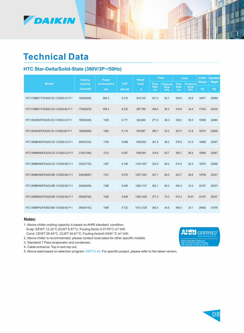
Technical Data
Model
Notes:1. Above chiller cooling capacity is based on AHRI standard condition:
2. Evap: EEWT 12.22°C,ELWT 6.67°C; Fouling factor 0.0176°C m / kW;2. Cond: CEWT 29.44°C, CLWT 34.61°C; Fouling factor0.0440 °C m / kW;
2. Above chiller is recommended, please contact local sales for other specific models;
3. Standard:1 Pass evaporator and condenser;
4. Cable entrance: Top in and top out;
5. Above data based on selection program DST13.40. For specific project, please refer to the latest version.
Cooling
capacity
Power
Consumption
COP
kW/ kW AA
Chiller
Weight
Operation
Weight
Kg Kg
HTC113MBE71F/E3620-CE-1/C3620-CLYY-1
HTC113MBE71F/E3620-CE-1/C3620-BLYY-1
HTC126LBH83F/E4220-CE-1/C3620-CLYY-1
HTC126LBH83F/E4220-CE-1/C3620-BLYY-1
HTC126MBH83F/E4220-CE-1/C3620-CLYY-1
HTC126MBHN0F/E4220-CE-1/C3620-CLYY-1
HTC126MBHN0F/E4220-CE-1/C3620-BLYY-1
HTC126MBHN0F/E4220-BE-1/C3620-BLYY-1
HTC126MBHN0F/E4220-BE-1/C4220-BLYY-1
HTC126MBGN2F/E4220-BE-1/C4220-BLYY-1
HTC126MBFN2F/E4820-BE-1/C4820-BLYY-1
HTC Star-Delta/Solid-State (380V/3P~/50Hz)
Tons(kW) kW
Rated
Load
Flow RateL/s
Flow RateL/s
Pressure DropkPa
Pressure DropkPa
Evap. Cond.
1600(5626)
1700(5979)
1800(6329)
1900(6680)
2000(7032)
2100(7384)
2200(7735)
2300(8087)
2400(8438)
2500(8790)
2600(9142)
905.3
959.4
1026
1082
1159
1212
1267
1331
1386
1506
1598
6.215
6.232
6.171
6.174
6.068
6.097
6.106
6.075
6.090
5.838
5.722
815;745
867;789
922;840
976;887
1049;953
1090;991
1145;1037
1207;1091
1262;1137
1385;1250
1473;1329
241.5
256.6
271.6
286.7
301.8
316.9
332.0
347.1
362.1
377.3
392.4
82.7
92.3
48.3
53.2
58.3
63.7
69.3
60.5
65.3
70.3
44.8
300.0
318.9
338.2
357.0
376.9
395.7
414.5
433.7
452.4
474.3
495.0
40.9
34.4
50.5
41.8
61.0
66.4
54.3
58.8
32.4
34.61
23.1
16977
17343
19008
19374
18995
18995
19374
19759
22187
22187
26482
20068
20434
22480
22846
22467
22467
22846
23231
26337
26337
31978

09
Dimensions
1、It's difficult to avoid deviation during design and manufacture;
2、A,B,C dimension deviation ±13mm and above dimension without insulation.
Notes:
Dimensions(mm) Evap. pipe connection(mm)Model
Cond. pipe connection(mm)
A B C D E H F J AA ODODG K BB
HTS079~087 (380V/3P~/50Hz)
A
D
C
F
J
G
B
E
AA
AA
BB
BB
K
H
c
HTS079~087/E2609/C2209
HTS079~087/E2612/C2212
HTS079~087/E2609/C2609
HTS079~087/E2612/C2612
HTS079~087/E3009/C2609
HTS079~087/E3012/C2612
HTS079~087/E3009/C3009
HTS079~087/E3012/C3012
HTS079~087/E3609/C3009
HTS079~087/E3612/C3012
HTS079~087/E3612/C3612
3360
4246
3294
4180
3405
4291
3420
4300
3464
4350
4350
1994
1994
1972
1972
2022
2022
2045
2045
2445
2445
2598
2010
2010
2144
2144
2258
2258
2397
2397
2427
2427
2690
2808
3694
2808
3694
2808
3694
2808
3694
2808
3694
3694
1041
1041
1105
1105
1225
1225
1276
1276
1682
1682
1834
102
102
102
102
102
102
102
102
102
102
102
979
979
1102
1102
1134
1134
1273
1273
1226
1226
1490
281
281
281
281
331
331
331
331
408
408
406
180
180
180
180
206
206
206
206
248
248
248
φ219
φ219
φ219
φ219
φ273
φ273
φ273
φ273
φ273
φ273
φ273
824
824
824
824
944
944
944
944
1351
1351
1425
426
426
469
469
469
469
520
520
520
520
596
145
145
180
180
180
180
206
206
206
206
248
φ219
φ219
φ219
φ219
φ219
φ219
φ273
φ273
φ273
φ273
φ325
10
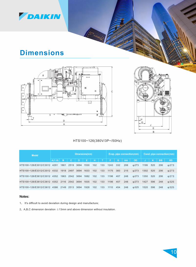
Dimensions
1、 It's difficult to avoid deviation during design and manufacture;
2、A,B,C dimension deviation ±13mm and above dimension without insulation.
Notes:
Dimensions(mm) Evap. pipe connection(mm)Model
Cond. pipe connection(mm)
B C D E H F J AA ODODG K BB
HTS100~126(380V/3P~/50Hz)
HTS100~126/E3012/C3012
HTS100~126/E3312/C3012
HTS100~126/E3612/C3012
HTS100~126/E3612/C3612
HTS100~126/E3912/C3612
1861
1918
1963
2116
2149
2519
2497
2542
2542
2513
3694
3694
3694
3694
3694
1530
1633
1682
1835
1928
102
102
102
102
102
133
133
133
133
133
1243
1175
1196
1196
1110
332
383
407
407
454
206
215
248
248
248
φ273
φ273
φ273
φ273
φ325
1199
1302
1350
1427
1520
520
520
520
596
596
206
206
206
248
248
φ273
φ273
φ273
φ325
φ325
4291
4332
4352
4352
4386
A(1.0) T
A
D
C
T
AA
AA
BB
BB
H
GJ
E
B
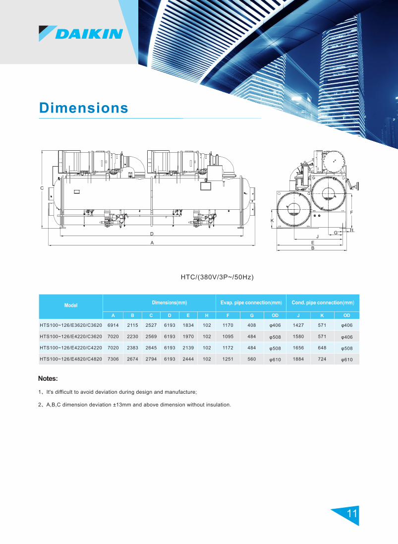
Dimensions
11
1、It's difficult to avoid deviation during design and manufacture;
2、A,B,C dimension deviation ±13mm and above dimension without insulation.
Notes:
HTC/(380V/3P~/50Hz)
Dimensions(mm) Evap. pipe connection(mm)Model
Cond. pipe connection(mm)
B C D E H F J ODODG
HTS100~126/E3620/C3620
HTS100~126/E4220/C3620
HTS100~126/E4220/C4220
HTS100~126/E4820/C4820
6914
7020
7020
7306
2115
2230
2383
2674
2527
2569
2645
2794
6193
6193
6193
6193
1834
1970
2139
2444
102
102
102
102
1170
1095
1172
1251
408
484
484
560
φ406
φ508
φ508
φ610
1427
1580
1656
1884
571
571
648
724
φ406
φ406
φ508
φ610
A K
A
D
C
F
K
HG
B
J
E

Vessel Code
Water connection
Marine water box
Insulation
Flow switch
Shock absorption Device
Warranty Extension
Factory Test
GB Standard(1.0MPa)
Victaulic groove ready
None
20 mm insulation on evaporator and cold surface
Differential Pressure Switch
Rubber cushion
None
Performance Test
ASME
Flange
option
40 mm insulation on evaporator and cold surface
Thermal flow switch /Paddle type
Spring isolator
1-4 Year
1-4 point witness test
Items Standard Options
Options
Startup Envelope
CE
WT
℃
ELWT ℃
Notes: The inlet and outlet temperature difference is 5℃ based on electronic expansion valve.
(8 ,30) (30,30)
(30,20)
(8 ,8)
12
40
30
20
10
00 10 20 30 40
Notes: 40mm insulation on evaporator shell and 20mm on water head cap.

Application
Supply Voltage
Phase Unbalance Rate
Frequency
Operating Temperature
Relative Humidity
Atmospheric Corrosive Gas Contents
Installation
Heat Exchange Tube Waterside Pressure
Rated voltage ± 10%
±2%
Rated frequency ± 2%Hz
3~40℃
90%
3Sulfur dioxide 10 mg/m
3Hydrogen fluoride 5 mg/m
3Hydrogen sulfide 5 mg/m
3Nitrogen oxide 5 mg/m
3Nitrogen 1 mg/m
3Hydrogen chloride 5 mg/m
Indoor installation, no rain or direct sunlight (for installations of the outdoor, seaside, chemical plant, or places of high concentration of corrosive gas, please contact the local DAIKIN office and distributors)
Standard chiller 1.0MPa
The running condition of the chiller is as follows:
Using standard benchmark chiller running environment is as follows:
13
Water Quality Management
When the chiller is running, the water quality of cooling water, chilled water will directly affect the
machine performance and service life. So you must survey water quality in advance. And manage the
water quality.
The following table contains some parameters of the water quality of open system:
Chiller ReferenceValueItem
Corrosion ScalingItem
PH(25℃)
(25℃)Electrical Conductivity
(PH=4.8 )Acid Consumption
Full Hardness
FeIron
Sulfateion SO 42-
Sulphion S 2-
O
O
O
O
O
OSiOSilicon Oxide 2
ClChloridion -
O
O
O
O
O
O
O
<6.5~8.0
<800
<100
<200
<1.0
<200
Not Detected
<50
<200
<1.0
_
μs/cm
mg(CaCO )/L3
mg(CaCO )/L3
mg(Fe)/L
m g /LSO 42-
mg(S )/L2-
mg(SiO )/L2
mg(Cl )/L-
mg(NH )/L+4NHAmmoniumion +
4
Base Items
Reference Items
Notes:
1. "O" in the table the relevant factors of corrosion or scaling tendency.
2. We recommend you add water process device and contact Daikin professional servicer to deal with it.

33, CheCheng Road, Economical and Technology Development District, Wuhan, Hubei, China.P.C. 430056
Subject to change without notice
All RIGHTS RESERVED
Version: PMHHTS001
Supersede:PMHTS001
Effective Date: 201805