Wallboard Display System Software - Avaya Supportiv Preface - General Information The CMS Wallboard...
80
Wallboard Display System Software Release 3, Version 8 (Compatible with CMS R3V8) October 2000
Transcript of Wallboard Display System Software - Avaya Supportiv Preface - General Information The CMS Wallboard...
Wallboard DisplaySystem SoftwareRelease 3, Version 8(Compatible with CMS R3V8)
October 2000
Wallboard Display SystemVersion 3 Release 8
(CMS V3R8 compatible)Administration
Table of contentsPreface
General Information . . . . . . . . . . . . . . . . . . . . . iv
Chapter 1 IntroductionGeneral Information . . . . . . . . . . . . . . . . . . . . . 1-1Description of WDS . . . . . . . . . . . . . . . . . . . . . 1-2Helpline/Escalation . . . . . . . . . . . . . . . . . . . . . 1-3
Who to Contact . . . . . . . . . . . . . . . . . . . . 1-3After the Initial Contact . . . . . . . . . . . . . . . . 1-4
Chapter 2 User BasicsGeneral Information . . . . . . . . . . . . . . . . . . . . . 2-1Terminology . . . . . . . . . . . . . . . . . . . . . . . . . 2-2Moving Around the WDS Interface. . . . . . . . . . . . . . 2-3
Making a Menu Selection . . . . . . . . . . . . . . . 2-3Special Keys . . . . . . . . . . . . . . . . . . . . . 2-3
Screen-Labeled Keys (SLK’s) . . . . . . . . . . . . . . . . 2-5Accessing WDS . . . . . . . . . . . . . . . . . . . . . . . 2-6Exiting WDS . . . . . . . . . . . . . . . . . . . . . . . . . 2-7
Chapter 3 Main MenuGeneral Information . . . . . . . . . . . . . . . . . . . . . 3-1WDS Main Menu (Split Data Installation). . . . . . . . . . . 3-2WDS Main Menu (VDN Data Installation) . . . . . . . . . . 3-3Main Menu Screen-Labeled Keys . . . . . . . . . . . . . . 3-4
Chapter 4 Message AdministrationGeneral Information. . . . . . . . . . . . . . . . . . . . . . 4-1Message Administration Screen . . . . . . . . . . . . . . . 4-2
Purpose . . . . . . . . . . . . . . . . . . . . . . . . 4-2Creating, Scheduling and Storing Wallboard Messages . . . 4-3Displaying Wallboard Messages . . . . . . . . . . . . . . . 4-4Deleting Wallboard Messages . . . . . . . . . . . . . . . . 4-5Changing Wallboard Message Attributes. . . . . . . . . . . 4-6Starting/Stopping Wallboard Messages . . . . . . . . . . . 4-7Listing Wallboard Messages. . . . . . . . . . . . . . . . . . 4-8Priority Messages. . . . . . . . . . . . . . . . . . . . . . . 4-10Wallboard Message Screen SLK’s. . . . . . . . . . . . . . 4-11
ii
Chapter 5 Change Wallboard ConfigurationGeneral Information . . . . . . . . . . . . . . . . . . . . . 5-1Change Wallboard Configuration Screen (Split Data) . . . . 5-2
Purpose . . . . . . . . . . . . . . . . . . . . . . . 5-2Change Wallboard Configuration Screen (VDN Data) . . . . 5-3
Purpose . . . . . . . . . . . . . . . . . . . . . . . 5-3Board Description Section . . . . . . . . . . . . . . . . . . 5-4
Configuration Number . . . . . . . . . . . . . . . . 5-4Status . . . . . . . . . . . . . . . . . . . . . . . . 5-4Serial TTY Device . . . . . . . . . . . . . . . . . . 5-4Wallboard Address . . . . . . . . . . . . . . . . . . 5-4Display Mode . . . . . . . . . . . . . . . . . . . . . 5-5Normal . . . . . . . . . . . . . . . . . . . . . . . . 5-5Thres1 (Threshold 1) . . . . . . . . . . . . . . . . . 5-5Thres2 (Threshold 2) . . . . . . . . . . . . . . . . . 5-5Refresh . . . . . . . . . . . . . . . . . . . . . . . . 5-5
ACD Data Display Section . . . . . . . . . . . . . . . . . . 5-6Data Heading . . . . . . . . . . . . . . . . . . . . . 5-6Data . . . . . . . . . . . . . . . . . . . . . . . . . 5-6Thres1 (Threshold 1) . . . . . . . . . . . . . . . . . 5-8Thres2 (Threshold 2) . . . . . . . . . . . . . . . . . 5-8Mode . . . . . . . . . . . . . . . . . . . . . . . . . 5-8Alarm . . . . . . . . . . . . . . . . . . . . . . . . . 5-8Freq (Frequency) . . . . . . . . . . . . . . . . . . . 5-8Split (Split Data Installation). . . . . . . . . . . . . . 5-8VDN Group Name (VDN Data Installation) . . . . . . 5-8ACD . . . . . . . . . . . . . . . . . . . . . . . . . 5-8
Change Wallboard Configuration Screen SLK’s . . . . . . . 5-9
Chapter 6 VDN Group AssignmentGeneral Information . . . . . . . . . . . . . . . . . . . . . 6-1VDN Group Assignments Screen . . . . . . . . . . . . . . 6-2
Purpose . . . . . . . . . . . . . . . . . . . . . . . . 6-2 Creating and Storing VDN Groups. . . . . . . . . . . . . . 6-3 Deleting VDN Groups . . . . . . . . . . . . . . . . . . . . 6-4 Changing VDN Groups. . . . . . . . . . . . . . . . . . . . 6-5 Listing VDNs in a VDN Group . . . . . . . . . . . . . . . . 6-6
VDN Group Assignments Screen SLK’s . . . . . . . . . . . 6-7
Chapter 7 Start/Stop Wallboard DisplayGeneral Information . . . . . . . . . . . . . . . . . . . . . 7-1Start/Stop Wallboard Display Screen . . . . . . . . . . . . 7-2
To Start All the Wallboards . . . . . . . . . . . . . . 7-2To Stop All the Wallboards . . . . . . . . . . . . . . 7-2
Start/Stop Wallboard Display Screen SLK’s . . . . . . . . . 7-3
iii
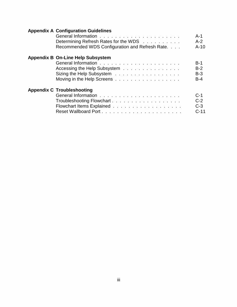
Appendix A Configuration GuidelinesGeneral Information . . . . . . . . . . . . . . . . . . . . . A-1Determining Refresh Rates for the WDS . . . . . . . . . . A-2Recommended WDS Configuration and Refresh Rate. . . . A-10
Appendix B On-Line Help SubsystemGeneral Information . . . . . . . . . . . . . . . . . . . . . B-1Accessing the Help Subsystem . . . . . . . . . . . . . . . B-2Sizing the Help Subsystem . . . . . . . . . . . . . . . . . B-3Moving in the Help Screens . . . . . . . . . . . . . . . . . B-4
Appendix C TroubleshootingGeneral Information . . . . . . . . . . . . . . . . . . . . . C-1Troubleshooting Flowchart . . . . . . . . . . . . . . . . . . C-2Flowchart Items Explained . . . . . . . . . . . . . . . . . . C-3Reset Wallboard Port . . . . . . . . . . . . . . . . . . . . . C-11
iv
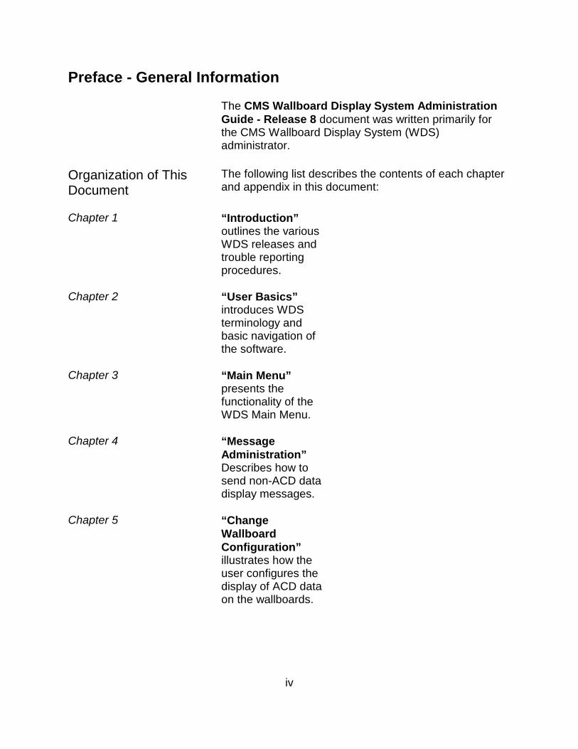
Preface - General Information
The CMS Wallboard Display System AdministrationGuide - Release 8 document was written primarily forthe CMS Wallboard Display System (WDS)administrator.
Organization of ThisDocument
The following list describes the contents of each chapterand appendix in this document:
Chapter 1 “Introduction”outlines the variousWDS releases andtrouble reportingprocedures.
Chapter 2 “User Basics”introduces WDSterminology andbasic navigation ofthe software.
Chapter 3 “Main Menu”presents thefunctionality of theWDS Main Menu.
Chapter 4 “MessageAdministration”Describes how tosend non-ACD datadisplay messages.
Chapter 5 “ChangeWallboardConfiguration”illustrates how theuser configures thedisplay of ACD dataon the wallboards.
v
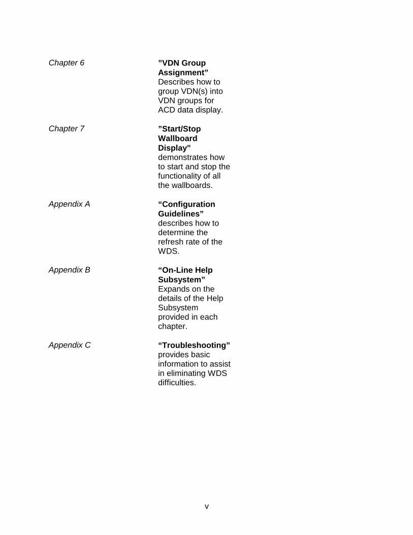
Chapter 6 ”VDN GroupAssignment”Describes how togroup VDN(s) intoVDN groups forACD data display.
Chapter 7 ”Start/StopWallboardDisplay”demonstrates howto start and stop thefunctionality of allthe wallboards.
Appendix A “ConfigurationGuidelines”describes how todetermine therefresh rate of theWDS.
Appendix B “On-Line HelpSubsystem”Expands on thedetails of the HelpSubsystemprovided in eachchapter.
Appendix C “Troubleshooting”provides basicinformation to assistin eliminating WDSdifficulties.
Introduction 1-1
————————————————————————————————————————————————————————————————————————————————————————————————————————————————————————————————
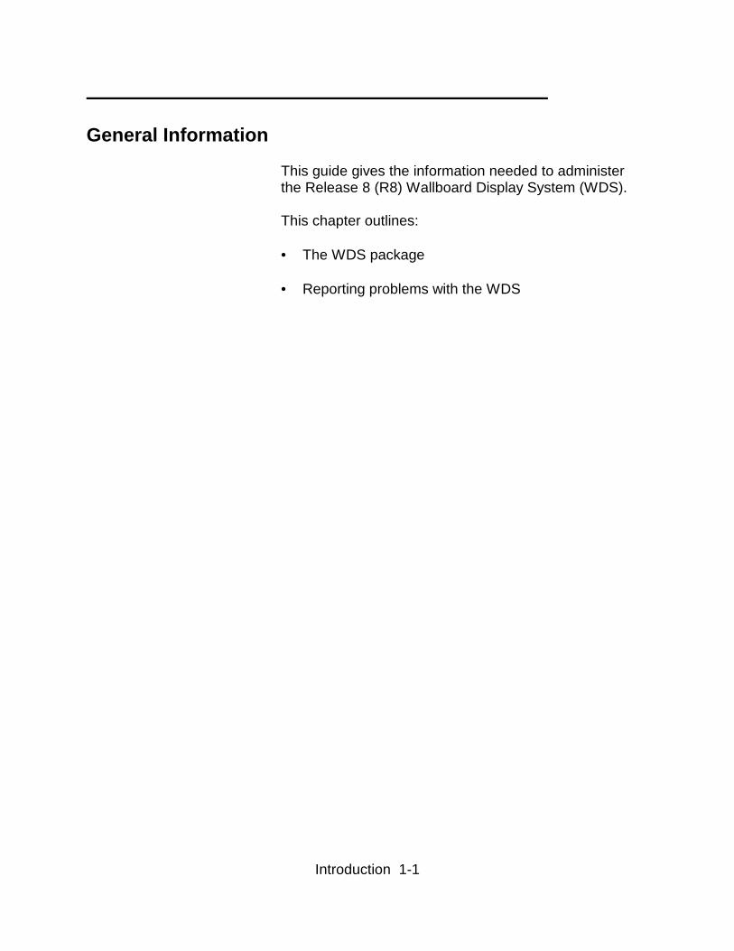
General Information
This guide gives the information needed to administerthe Release 8 (R8) Wallboard Display System (WDS).
This chapter outlines:
• The WDS package • Reporting problems with the WDS

Introduction 1-2
————————————————————————————————
Description of WDS
The Release 8 Wallboard Display System (R8 WDS) is asoftware product used by business customers that havean Lucent Technologies Release 3 Version 2 CallManagement System (R3V2 CMS) load 3ragh or newer.The WDS accesses real-time and historical split or VDNdata and transmits the user requested data to Spectrum4200C (or other compatible manufacturers) wallboard(s)for display. The wallboard software is user accessible viaa CMS “Main Menu Addition” on CMS supportedterminals. R8 WDS software has the ability to access CMS splitdata or CMS VDN data, not both. The initial installationof the software is split based. To upgrade the R8 WDSsoftware to be VDN based, an additional charge will beincurred by the user. WDS has the ability to combine historical and real-timesplit or VDN data for display.
Introduction 1-3
————————————————————————————————
Helpline/Escalation
—————————— Who to Contact For a WDS problem, call Avaya Professional Services
Monday through Friday 6am-6pm MST/MDT on 1-877-927-6662 to report the problem and obtain a troubleticket number to escalate the problem through theservices organization. Be prepared to give the following information: • Your full name, your organization, and a phone
number where Avaya can contact you concerning thetrouble.
• The Installation Location (IL) number.
This is a 10-digit number from an Avaya databasethat helps service personnel look up the details ofyour WDS installation and environment.
• The phone number that off-site engineer can use to
remotely dial into your CMS system. • Your computer model, switch model, and any unique
characteristics of your Wallboard environment youthink might be relevant.
• The type and symptoms of the problem - describe
exactly.
NOTE: If the trouble report is not within 15 days ofinitial installation, you will be invoiced for the work doneto troubleshoot your system. Service contracts coveringCMS do not cover WDS software.
Introduction 1-4
————————————————————————————————
After the Initial Contact When you report the trouble to Avaya, you shouldreceive a trouble-ticket number. Be sure to get thisnumber from the person you are talking to. Use thisnumber when you talk to an Avaya representative aboutthe problem after the initial report.
According to Avaya internal rules, the trouble ticket mustbe cleared. This means that you must receivenotification that the trouble has been cleared up, andagree that it has. If you receive no such notification in areasonable period, call 1-877-927-6662 again and askfor a resolution on your trouble ticket number.

User Basics 2-1
————————————————————————————————
General InformationThis Chapter explains the basics of the WDS userinterface. The following information is covered in thischapter:
• Necessary terms for using WDS • Moving around WDS • Screen-Labeled Keys (SLK) • Accessing WDS • Exiting WDS
User Basics 2-2
————————————————————————————————
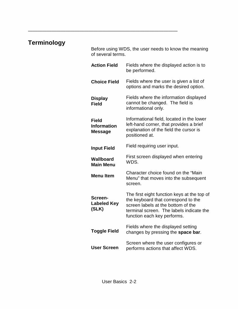
Terminology Before using WDS, the user needs to know the meaningof several terms. Action Field Choice Field DisplayField FieldInformationMessage Input Field Wallboard Main Menu Menu Item Screen-Labeled Key (SLK) Toggle Field User Screen
Fields where the displayed action is tobe performed. Fields where the user is given a list ofoptions and marks the desired option. Fields where the information displayedcannot be changed. The field isinformational only. Informational field, located in the lowerleft-hand corner, that provides a briefexplanation of the field the cursor ispositioned at. Field requiring user input. First screen displayed when enteringWDS. Character choice found on the “MainMenu” that moves into the subsequentscreen. The first eight function keys at the top ofthe keyboard that correspond to thescreen labels at the bottom of theterminal screen. The labels indicate thefunction each key performs. Fields where the displayed settingchanges by pressing the space bar. Screen where the user configures orperforms actions that affect WDS.
User Basics 2-3
————————————————————————————————
Moving Around the WDS Interface
—————————————————————
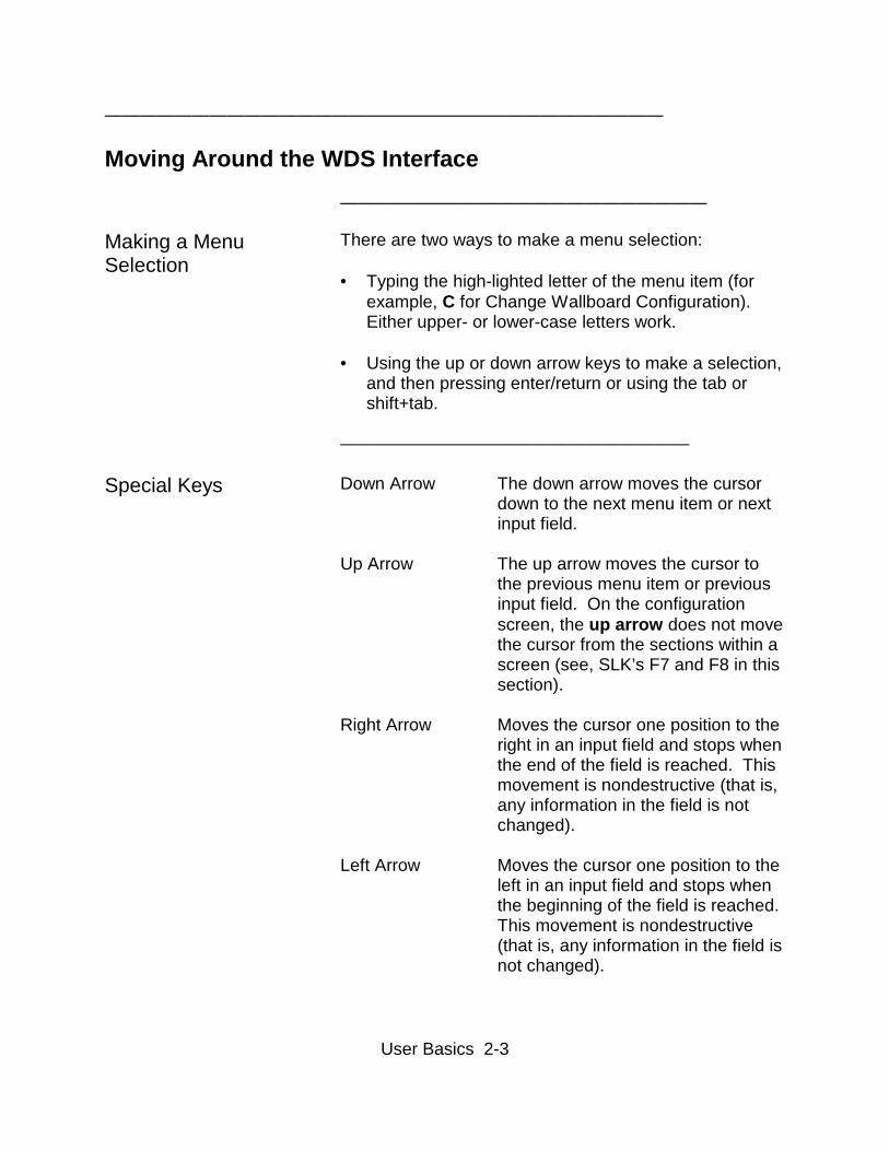
Making a MenuSelection
There are two ways to make a menu selection: • Typing the high-lighted letter of the menu item (for
example, C for Change Wallboard Configuration).Either upper- or lower-case letters work.
• Using the up or down arrow keys to make a selection,
and then pressing enter/return or using the tab orshift+tab.
————————————————————
Special Keys Down Arrow The down arrow moves the cursordown to the next menu item or nextinput field.
Up Arrow The up arrow moves the cursor tothe previous menu item or previousinput field. On the configurationscreen, the up arrow does not movethe cursor from the sections within ascreen (see, SLK’s F7 and F8 in thissection).
Right Arrow Moves the cursor one position to theright in an input field and stops whenthe end of the field is reached. Thismovement is nondestructive (that is,any information in the field is notchanged).
Left Arrow Moves the cursor one position to theleft in an input field and stops whenthe beginning of the field is reached.This movement is nondestructive(that is, any information in the field isnot changed).
User Basics 2-4
————————————————————————————————
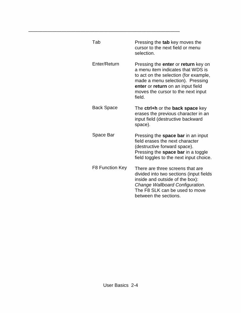
Tab
Enter/Return
Back Space
Space Bar
F8 Function Key
Pressing the tab key moves thecursor to the next field or menuselection.
Pressing the enter or return key ona menu item indicates that WDS isto act on the selection (for example,made a menu selection). Pressingenter or return on an input fieldmoves the cursor to the next inputfield.
The ctrl+h or the back space keyerases the previous character in aninput field (destructive backwardspace).
Pressing the space bar in an inputfield erases the next character(destructive forward space).Pressing the space bar in a togglefield toggles to the next input choice.
There are three screens that aredivided into two sections (input fieldsinside and outside of the box):Change Wallboard Configuration.The F8 SLK can be used to movebetween the sections.
User Basics 2-5
————————————————————————————————
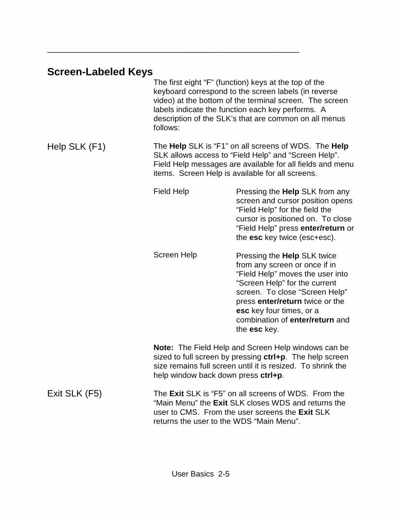
Screen-Labeled KeysThe first eight “F” (function) keys at the top of thekeyboard correspond to the screen labels (in reversevideo) at the bottom of the terminal screen. The screenlabels indicate the function each key performs. Adescription of the SLK’s that are common on all menusfollows:
Help SLK (F1) The Help SLK is “F1” on all screens of WDS. The HelpSLK allows access to “Field Help” and “Screen Help”.Field Help messages are available for all fields and menuitems. Screen Help is available for all screens.
Field Help
Screen Help
Pressing the Help SLK from anyscreen and cursor position opens“Field Help” for the field thecursor is positioned on. To close“Field Help” press enter/return orthe esc key twice (esc+esc).
Pressing the Help SLK twicefrom any screen or once if in“Field Help” moves the user into“Screen Help” for the currentscreen. To close “Screen Help”press enter/return twice or theesc key four times, or acombination of enter/return andthe esc key.
Exit SLK (F5)
Note: The Field Help and Screen Help windows can besized to full screen by pressing ctrl+p. The help screensize remains full screen until it is resized. To shrink thehelp window back down press ctrl+p.
The Exit SLK is “F5” on all screens of WDS. From the“Main Menu” the Exit SLK closes WDS and returns theuser to CMS. From the user screens the Exit SLKreturns the user to the WDS “Main Menu”.
User Basics 2-6
————————————————————————————————
Accessing WDS
WDS is a menu-driven system that is operated through aseries of interactive screens. To use WDS, the usermust first be given access in CMS to the “Main MenuAddition” for WDS. (See CMS Administration Guide forMain Menu Addition)

User Basics 2-7
————————————————————————————————
Exiting WDS
From the WDS “Main Menu” press the Exit SLK (F5).WDS is closed and the user is returned to the CMS“Main Menu”.
Main Menu 3-1
————————————————————————————————
General Information
This chapter covers the functionality of the WDS MainMenu.
WDS R8 software has the ability to access CMS splitdata or CMS VDN data, but not both. The defaultinstallation of the WDS software is split based.
The Main Menu screens for both split data and VDN datainstallations are depicted in this chapter.
The following information is covered in this chapter:
• Split Main Menu for split data installation • VDN Main Menu for VDN data installation • Menu Items on the Main Menu • Main Menu Screen-Labeled Keys (SLK’s)
Main Menu 3-2
————————————————————————————————
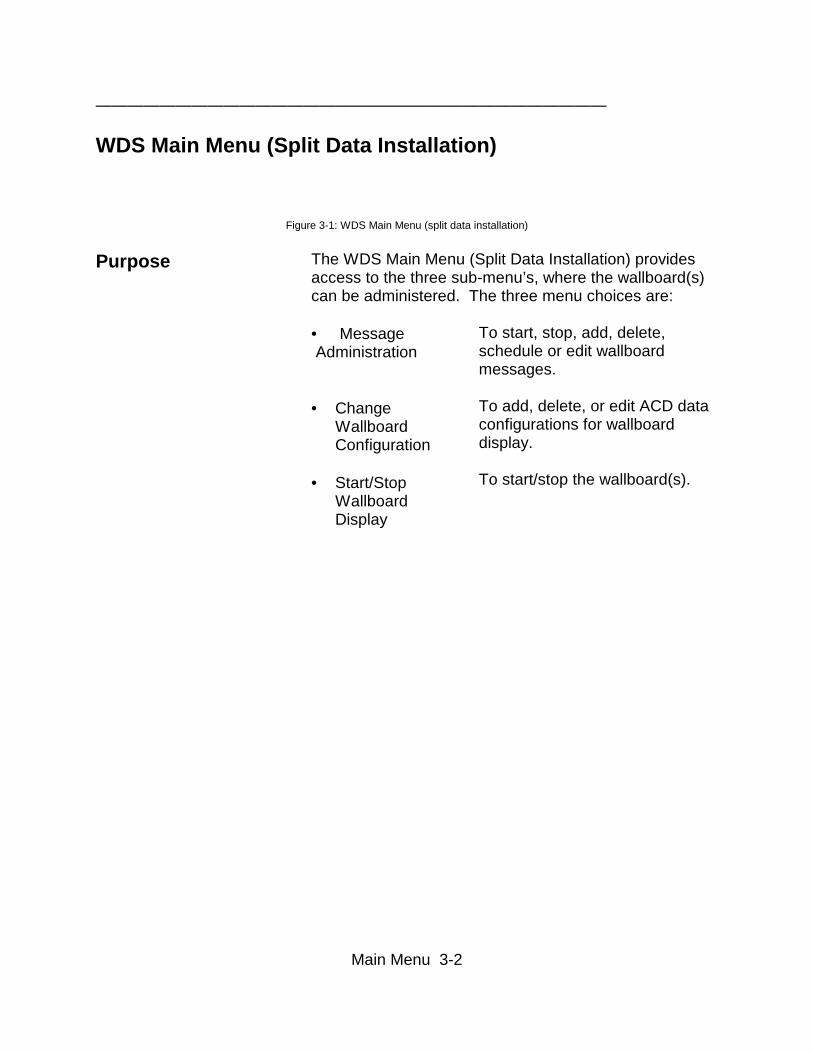
WDS Main Menu (Split Data Installation)
Figure 3-1: WDS Main Menu (split data installation) Purpose The WDS Main Menu (Split Data Installation) provides
access to the three sub-menu’s, where the wallboard(s)can be administered. The three menu choices are: • Message Administration • Change
WallboardConfiguration
• Start/Stop
WallboardDisplay
To start, stop, add, delete,schedule or edit wallboardmessages. To add, delete, or edit ACD dataconfigurations for wallboarddisplay. To start/stop the wallboard(s).

Main Menu 3-3
————————————————————————————————
WDS Main Menu (VDN Data Installation)
Figure 3-2: WDS Main Menu (VDN data installation)
Purpose The WDS Main Menu (VDN Data Installation) providesaccess to the three sub-menu’s, where the wallboard(s)can be administered. The three menu choices are:
• Message Administration
• ChangeWallboardConfiguration
• Start/Stop
WallboardDisplay
To start, stop, add, delete,schedule or edit wallboardmessages.
To add, delete, or edit ACD dataconfigurations for wallboarddisplay.
To start/stop the wallboard(s).
Main Menu 3-4
————————————————————————————————
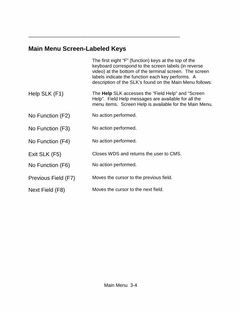
Main Menu Screen-Labeled Keys
The first eight “F” (function) keys at the top of thekeyboard correspond to the screen labels (in reversevideo) at the bottom of the terminal screen. The screenlabels indicate the function each key performs. Adescription of the SLK’s found on the Main Menu follows:
Help SLK (F1) The Help SLK accesses the “Field Help” and “ScreenHelp”. Field Help messages are available for all themenu items. Screen Help is available for the Main Menu.
No Function (F2) No action performed.
No Function (F3) No action performed.
No Function (F4) No action performed.
Exit SLK (F5) Closes WDS and returns the user to CMS.
No Function (F6) No action performed.
Previous Field (F7) Moves the cursor to the previous field.
Next Field (F8) Moves the cursor to the next field.
Wallboard Message Screen 4-1
————————————————————————————————
General InformationThis chapter covers the administration of non-ACD datadisplay messages, the communication of informationnot necessarily related to the management of the callcenter. From the Message Administration screen theuser can:
• Create, Schedule and Store Wallboard Messages • Display Wallboard Messages • Delete Wallboard Messages • Change Wallboard Message Attributes • Start/Stop Wallboard Messages • List All Wallboard Messages • Create a Priority Message
Wallboard Message Screen 4-2
————————————————————————————————
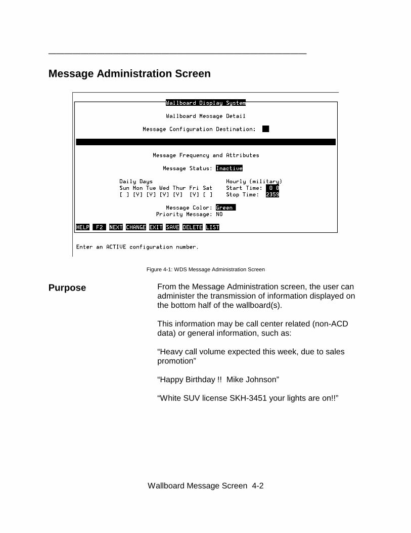
Message Administration Screen
Figure 4-1: WDS Message Administration Screen
Purpose From the Message Administration screen, the user canadminister the transmission of information displayed onthe bottom half of the wallboard(s).
This information may be call center related (non-ACDdata) or general information, such as:
“Heavy call volume expected this week, due to salespromotion”
“Happy Birthday !! Mike Johnson”
“White SUV license SKH-3451 your lights are on!!”
Wallboard Message Screen 4-3
————————————————————————————————
Creating, Scheduling and Storing Wallboard Messages
To create and store a new Wallboard Message:
1. In the Message Destination field enter a validconfiguration number. This information can be foundin the “Change Wallboard Configuration” menu.
The Next SLK (F3) will step through defined message(s). 2. Move the cursor to the second input field
3. Type the new message 4. Press the Save SLK (F6)
Look for “Successful” message in lower left-hand cornerof the screen
WDS can hold up to 32 saved messages with 5 activemessages per board. The maximum length of amessage is 78 characters.
To schedule a message (default is Monday throughFriday - continuous/24 hours daily):
1. Move the cursor to the Daily Days toggle fields
2. Use the <SPACE BAR> to select the days of theweek for the message to be active: Y - active, space -inactive
3. Move the cursor to the Hourly input fields
4. Enter a military start and stop time for the message:hour 0 to 23, minute 0 to 59
5. Press the Save SLK (F6)
Wallboard Message Screen 4-4
————————————————————————————————
Displaying Wallboard Messages
To display a stored Wallboard Message:
1. Press the Next SLK (F3) 2. The first stored message along with the Message
Destination and Message Attributes will be displayedin all the fields on the screen
3. Press the Next SLK (F3) to display the next stored
message
Look for “Successful” message in lower left-hand cornerof the screen

Wallboard Message Screen 4-5
————————————————————————————————
Deleting Wallboard Messages
To delete a stored Wallboard Message:
1. Press the Next SLK (F3) until the desired messageand its attributes to be deleted is displayed.
2. Press the Delete SLK (F7).
Look for “Successful” message in lower left-hand cornerof the screen.
Wallboard Message Screen 4-6
————————————————————————————————
Changing Wallboard Message Attributes
To change a stored Wallboard Message Attributes:
1. Press the Next SLK (F3) until the desired messageand its attributes are displayed
2. Move the cursor to the input fields in the Message
Frequency and Attributes section (below messageinput field)
3. Change desired message attributes 4. Press the Change SLK (F4)
If the message input field or Message Destinationinput field is changed, press the Save SLK (F6)
Look for “Successful” message in lower left-hand cornerof the screen
Wallboard Message Screen 4-7
————————————————————————————————
Starting/Stopping Wallboard Messages
To start a Wallboard Message:
1. Press the Next SLK (F3) until the desired messageand its attributes to be deleted is displayed.
2. Move the cursor to the Message Status field 3. Use the <SPACE BAR> to set the field to Active 4. Press the Save SLK (F6) if the message was just
createdor
press the Change SLK (F4) for a stored message
5. Look for “Successful” message in lower left-handcorner of the screen
To stop a Wallboard Message:
1. Press the Next SLK (F3) until the desired messageand its attributes to be deleted is displayed.
2. Move the cursor to the Message Status input field 3. Use the <SPACE BAR> to set the field to Inactive 4. Press the Save SLK (F6) if the message was just
createdor
press the Change SLK (F4) for a stored message
Look for “Successful” message in lower left-hand cornerof the screen
NOTE: A wallboard message cannot be started if the wallboard software is not activated (seeChapter 8).
Wallboard Message Screen 4-8
————————————————————————————————
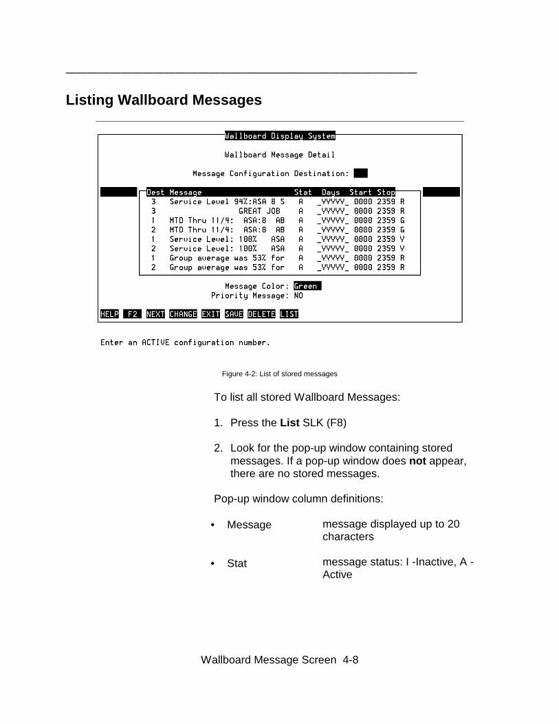
Listing Wallboard Messages
Figure 4-2: List of stored messages
To list all stored Wallboard Messages:
1. Press the List SLK (F8) 2. Look for the pop-up window containing stored
messages. If a pop-up window does not appear,there are no stored messages.
Pop-up window column definitions:
• Message
• Stat
message displayed up to 20characters
message status: I -Inactive, A -Active
Wallboard Message Screen 4-9
————————————————————————————————
• Days
• Start
• Stop
• Column 7
• Column 8
status of days of week formessage starting on Sunday: _ -message inactive, Y - messageactive
start time of message on activedays, military (hour 0 - 23, minute0 - 59
stop time of message on activedays, military (hour 0 - 23, minute0 - 59
message color: R - red, Y - yellow,G - green
priority message - P
Wallboard Message Screen 4-10
————————————————————————————————
Priority Messages
When a priority message is sent to a wallboard that iscurrently displaying a non-ACD data display message,the priority message is the only message displayed. Iftwo priority messages are sent to the same wallboard,only the first priority message that is activated will besent.
To send a Wallboard Priority Message:
1. Make sure the message to be broadcast has beenstored (See: Creating and Storing WallboardMessages 4-3)
2. Move the cursor to the Message Status input field
3. Use the <SPACE BAR> to toggle to ACTIVE option 4. Move the cursor to the Priority Message input field 5. Use the <SPACE BAR> to toggle to YES option 6. Press the Save SLK (F6) if the message was just
createdor
7. press the Change SLK (F4) for a stored message
Look for “Successful” message in lower left-hand cornerof the screen
Wallboard Message Screen 4-11
————————————————————————————————
Wallboard Message Screen SLK’s
The first eight “F” (function) keys at the top of thekeyboard correspond to the screen labels (in reversevideo) at the bottom of the terminal screen. The screenlabels indicate the function each key performs. Adescription of the SLK’s found on the MessageAdministration Screen follows:
Help SLK (F1) The Help SLK accesses the “Field Help” and “ScreenHelp”. Field Help messages are available for all the inputfields. Screen Help is available for the WallboardMessage Screen.
Next SLK (F3) Displays first stored message, continued depressionscycles through all the stored messages.
Wallboard Message Screen 4-12
————————————————————————————————
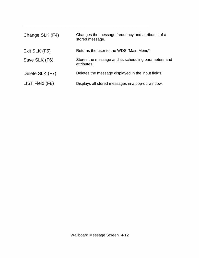
Change SLK (F4) Changes the message frequency and attributes of astored message.
Exit SLK (F5) Returns the user to the WDS “Main Menu”.
Save SLK (F6) Stores the message and its scheduling parameters andattributes.
Delete SLK (F7) Deletes the message displayed in the input fields.
LIST Field (F8) Displays all stored messages in a pop-up window.
Change Wallboard Configuration Screen 5-1
————————————————————————————————
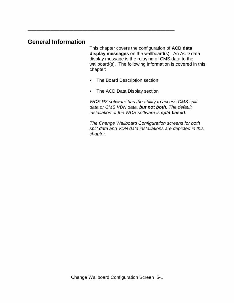
General InformationThis chapter covers the configuration of ACD datadisplay messages on the wallboard(s). An ACD datadisplay message is the relaying of CMS data to thewallboard(s). The following information is covered in thischapter:
• The Board Description section • The ACD Data Display section WDS R8 software has the ability to access CMS splitdata or CMS VDN data, but not both. The defaultinstallation of the WDS software is split based. The Change Wallboard Configuration screens for bothsplit data and VDN data installations are depicted in thischapter.
Change Wallboard Configuration Screen 5-2
————————————————————————————————
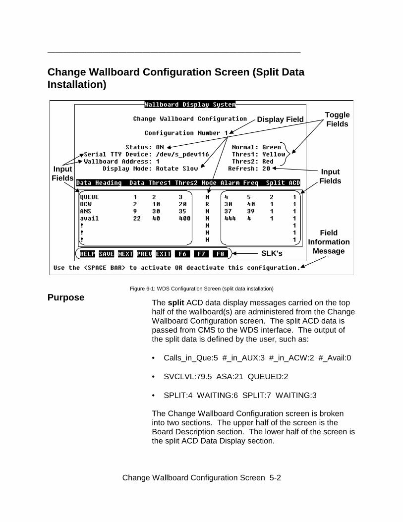
Change Wallboard Configuration Screen (Split DataInstallation)
Display Field ToggleFields
FieldInformation
Message
InputFields
SLK's
InputFields
Figure 6-1: WDS Configuration Screen (split data installation)
Purpose The split ACD data display messages carried on the tophalf of the wallboard(s) are administered from the ChangeWallboard Configuration screen. The split ACD data ispassed from CMS to the WDS interface. The output ofthe split data is defined by the user, such as: • Calls_in_Que:5 #_in_AUX:3 #_in_ACW:2 #_Avail:0 • SVCLVL:79.5 ASA:21 QUEUED:2 • SPLIT:4 WAITING:6 SPLIT:7 WAITING:3 The Change Wallboard Configuration screen is brokeninto two sections. The upper half of the screen is theBoard Description section. The lower half of the screen isthe split ACD Data Display section.
Change Wallboard Configuration Screen 5-3
————————————————————————————————
Change Wallboard Configuration Screen (VDN DataInstallation)
Figure 6-2: WDS Configuration Screen (split data installation) Purpose The VDN ACD data display messages carried on the top
half of the wallboard(s) are administered from theChange Wallboard Configuration screen. The VDN ACDdata which is the sum of VDNs in a VDN group, ispassed from CMS to the WDS interface. The output ofthis data is defined by the user, such as: • Calls_in_Que:5 #_in_AUX:3 #_in_ACW:2 #_Avail:0 • SVCLVL:79.5 ASA:21 QUEUED:2 • SPLIT:4 WAITING:6 SPLIT:7 WAITING:3 The Change Wallboard Configuration screen is brokeninto two sections. The upper half of the screen is theBoard Description section. The lower half of the screenis the ACD Data Display section.
Change Wallboard Configuration Screen 5-4
————————————————————————————————
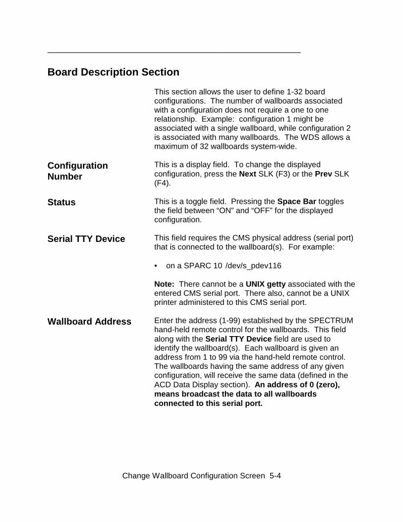
Board Description Section
This section allows the user to define 1-32 boardconfigurations. The number of wallboards associatedwith a configuration does not require a one to onerelationship. Example: configuration 1 might beassociated with a single wallboard, while configuration 2is associated with many wallboards. The WDS allows amaximum of 32 wallboards system-wide.
ConfigurationNumber
This is a display field. To change the displayedconfiguration, press the Next SLK (F3) or the Prev SLK(F4).
Status This is a toggle field. Pressing the Space Bar togglesthe field between “ON” and “OFF” for the displayedconfiguration.
Serial TTY Device This field requires the CMS physical address (serial port)that is connected to the wallboard(s). For example: • on a SPARC 10 /dev/s_pdev116 Note: There cannot be a UNIX getty associated with theentered CMS serial port. There also, cannot be a UNIXprinter administered to this CMS serial port.
Wallboard Address Enter the address (1-99) established by the SPECTRUMhand-held remote control for the wallboards. This fieldalong with the Serial TTY Device field are used toidentify the wallboard(s). Each wallboard is given anaddress from 1 to 99 via the hand-held remote control.The wallboards having the same address of any givenconfiguration, will receive the same data (defined in theACD Data Display section). An address of 0 (zero),means broadcast the data to all wallboardsconnected to this serial port.

Change Wallboard Configuration Screen 5-5
Display Mode This is a toggle field. Pressing the Space Bar toggles thefield between three display modes, each having threespeeds (slow, medium, and fast): • Auto - various modes automatically display the data.• Hold - data remains stationary.• Rotate - data travels from right to left.
This field is used to configure the display mode for thecurrently displayed configuration.
Normal This is a toggle field. Pressing the Space Bar togglesthe field between “Green”, “Yellow”, and “Red”. TheData_Heading:Data (see ACD Data Display section) willbe displayed in the Normal color if Thres1 (from theACD Data Display section) is not exceeded.
Thres1 (Threshold 1) This is a toggle field. Pressing the Space Bar togglesthe field between “Green”, “Yellow”, and “Red”. TheData_Heading:Data (see ACD Data Display section) willbe displayed in the Thres1 color if Thres1 (from the ACDData Display section) is exceeded and Thres2 (from theACD Data Display section) is not exceeded.
Thres2 (Threshold 2) This is a toggle field. Pressing the Space Bar togglesthe field between “Green”, “Yellow”, and “Red”. TheData_Heading:Data (see ACD Data Display section) willbe displayed in the Thres2 color if Thres2 (from the ACDData Display section) is exceeded.
Refresh This is an input field. Enter the time in seconds (updateinterval) that new data is sent to all wallboards. Refreshfield is not a single configuration setting, it affects allwallboards. The minimum is ten (10) seconds, but isdependent upon the users refresh rate established inCMS.
NOTE: The input in this field combined with Display Mode setting affects the presentation of data. The refresh rate should allow enough time forthe display mode to complete it’s presentation of data.
Change Wallboard Configuration Screen 5-6
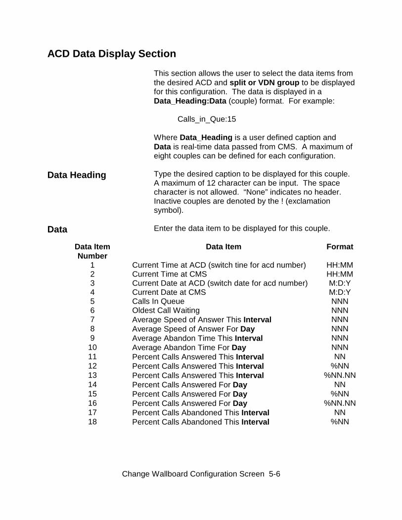
ACD Data Display Section
This section allows the user to select the data items fromthe desired ACD and split or VDN group to be displayedfor this configuration. The data is displayed in aData_Heading:Data (couple) format. For example:
Calls_in_Que:15
Where Data_Heading is a user defined caption andData is real-time data passed from CMS. A maximum ofeight couples can be defined for each configuration.
Data Heading Type the desired caption to be displayed for this couple.A maximum of 12 character can be input. The spacecharacter is not allowed. “None” indicates no header.Inactive couples are denoted by the ! (exclamationsymbol).
Data Enter the data item to be displayed for this couple.
Data ItemNumber
Data Item Format
1 Current Time at ACD (switch tine for acd number) HH:MM2 Current Time at CMS HH:MM3 Current Date at ACD (switch date for acd number) M:D:Y4 Current Date at CMS M:D:Y5 Calls In Queue NNN6 Oldest Call Waiting NNN7 Average Speed of Answer This Interval NNN8 Average Speed of Answer For Day NNN9 Average Abandon Time This Interval NNN
10 Average Abandon Time For Day NNN11 Percent Calls Answered This Interval NN12 Percent Calls Answered This Interval %NN13 Percent Calls Answered This Interval %NN.NN14 Percent Calls Answered For Day NN15 Percent Calls Answered For Day %NN16 Percent Calls Answered For Day %NN.NN17 Percent Calls Abandoned This Interval NN18 Percent Calls Abandoned This Interval %NN
Change Wallboard Configuration Screen 5-7
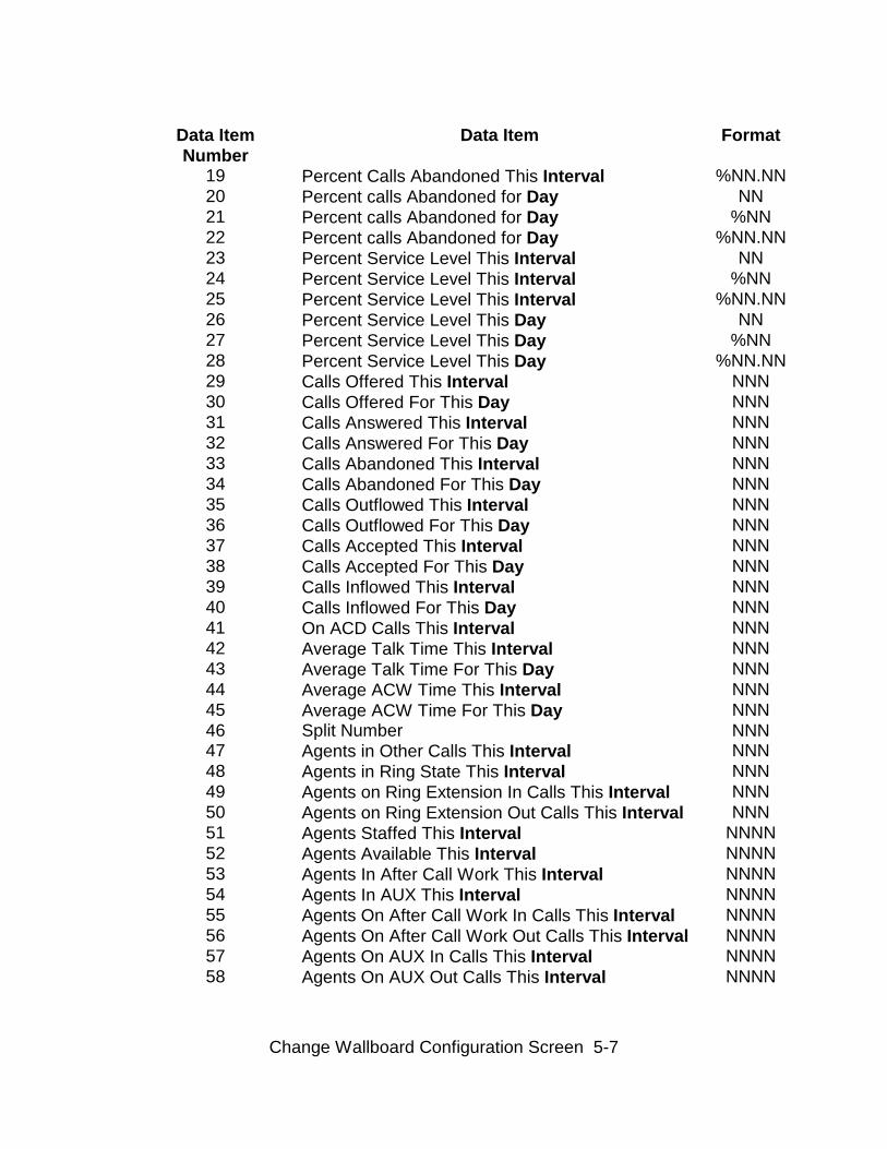
Data ItemNumber
Data Item Format
19 Percent Calls Abandoned This Interval %NN.NN20 Percent calls Abandoned for Day NN21 Percent calls Abandoned for Day %NN22 Percent calls Abandoned for Day %NN.NN23 Percent Service Level This Interval NN24 Percent Service Level This Interval %NN25 Percent Service Level This Interval %NN.NN26 Percent Service Level This Day NN27 Percent Service Level This Day %NN28 Percent Service Level This Day %NN.NN29 Calls Offered This Interval NNN30 Calls Offered For This Day NNN31 Calls Answered This Interval NNN32 Calls Answered For This Day NNN33 Calls Abandoned This Interval NNN34 Calls Abandoned For This Day NNN35 Calls Outflowed This Interval NNN36 Calls Outflowed For This Day NNN37 Calls Accepted This Interval NNN38 Calls Accepted For This Day NNN39 Calls Inflowed This Interval NNN40 Calls Inflowed For This Day NNN41 On ACD Calls This Interval NNN42 Average Talk Time This Interval NNN43 Average Talk Time For This Day NNN44 Average ACW Time This Interval NNN45 Average ACW Time For This Day NNN46 Split Number NNN47 Agents in Other Calls This Interval NNN48 Agents in Ring State This Interval NNN49 Agents on Ring Extension In Calls This Interval NNN50 Agents on Ring Extension Out Calls This Interval NNN51 Agents Staffed This Interval NNNN52 Agents Available This Interval NNNN53 Agents In After Call Work This Interval NNNN54 Agents In AUX This Interval NNNN55 Agents On After Call Work In Calls This Interval NNNN56 Agents On After Call Work Out Calls This Interval NNNN57 Agents On AUX In Calls This Interval NNNN58 Agents On AUX Out Calls This Interval NNNN
Change Wallboard Configuration Screen 5-8
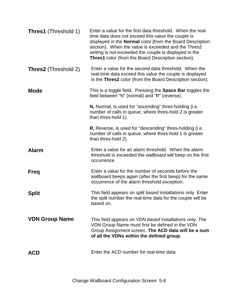
Thres1 (Threshold 1) Enter a value for the first data threshold. When the real-time data does not exceed this value the couple isdisplayed in the Normal color (from the Board Descriptionsection). When the value is exceeded and the Thres2setting is not exceeded the couple is displayed in theThres1 color (from the Board Description section).
Thres2 (Threshold 2) Enter a value for the second data threshold. When thereal-time data exceed this value the couple is displayedin the Thres2 color (from the Board Description section).
Mode This is a toggle field. Pressing the Space Bar toggles thefield between “N” (normal) and “R” (reverse).
N, Normal, is used for “ascending” thres-holding (i.e.number of calls in queue, where thres-hold 2 is greaterthan thres-hold 1).
R, Reverse, is used for “descending” thres-holding (i.e.number of calls in queue, where thres-hold 1 is greaterthan thres-hold 2).
Alarm Enter a value for an alarm threshold. When the alarmthreshold is exceeded the wallboard will beep on the firstoccurrence.
Freq Enter a value for the number of seconds before thewallboard beeps again (after the first beep) for the sameoccurrence of the alarm threshold exception.
Split
VDN Group Name
This field appears on split based installations only. Enterthe split number the real-time data for the couple will bebased on.
This field appears on VDN based installations only. TheVDN Group Name must first be defined in the VDNGroup Assignment screen. The ACD data will be a sumof all the VDNs within the defined group.
ACD Enter the ACD number for real-time data.
Change Wallboard Configuration Screen 5-9
Change Wallboard Configuration Screen SLK’s
The first eight “F” (function) keys at the top of thekeyboard correspond to the screen labels (in reversevideo) at the bottom of the terminal screen. The screenlabels indicate the function each key performs. Adescription of the SLK’s found on the WallboardMessage Screen follows:
Help SLK (F1) The Help SLK accesses the “Field Help” and “ScreenHelp”. Field Help messages are available for all the inputfields. Screen Help is available for the WallboardMessage Screen.
CHOICES SLK (F2) VDN based installation only. Displays VDN group names(cursor must be in VDN Group Name input field). Usethe up/down arrow keys to move between VDN groupnames and the enter/return key to select a VDN group.

Change Wallboard Configuration Screen 5-10
Save SLK (F2) Split based installations only. After creating a newconfiguration or editing an existing configuration, pressthe Save SLK “F2”. Saves only the configurationcurrently displayed.
Next SLK (F3) To change to the next configuration press the Next SLK“F3”. The WDS allows the setup of 1-32 configurations.If, the interface is displaying the 32nd configuration andthe Next SLK is pressed the 1st configuration will bedisplayed.
Prev SLK (F4) To change to the previous configuration press the PrevSLK “F4”. The WDS allows the setup of 1-32configurations. If, the interface is displaying the 1stconfiguration and the Prev SLK is pressed the 32ndconfiguration will be displayed.
Exit SLK (F5) Returns the user to the WDS “Main Menu”.
No Function (F6) In the split data installation, no action performed.
Save SLK (F6) VDN based installations only. After creating a newconfiguration or editing an existing configuration, pressthe Save SLK “F6”. Saves only the configurationcurrently displayed.
Previous Field (F7) Moves the cursor between screen sections (box on thescreen). The screen is divided into two sections: inputfields that are inside and outside the box.
Next Field (F8) Moves the cursor between screen sections (box on thescreen). The screen is divided into two sections: inputfields that are inside and outside the box.
VDN Group Assignment Screen 6-1
————————————————————————————————
General InformationThis chapter covers the administration of VDN GroupNames for display of ACD VDN data on wallboards.
WDS R8 software has the ability to access CMS splitdata or CMS VDN data, but not both. The defaultinstallation of the WDS software is split based. Thisscreen will not be present on default installations, onlyon upgrades.
The VDN Group Name is used in the VDN Group Nameinput field in the Change Wallboard Configuration screen.The VDNs associated with a VDN Group Name aresummed together to display the ACD data.
From the VDN Group Assignment screen the user can:
• Create and Store VDN Groups • Delete VDN Groups • Change VDN Groups • List VDNs in a VDN Group
VDN Group Assignment Screen 6-2
————————————————————————————————
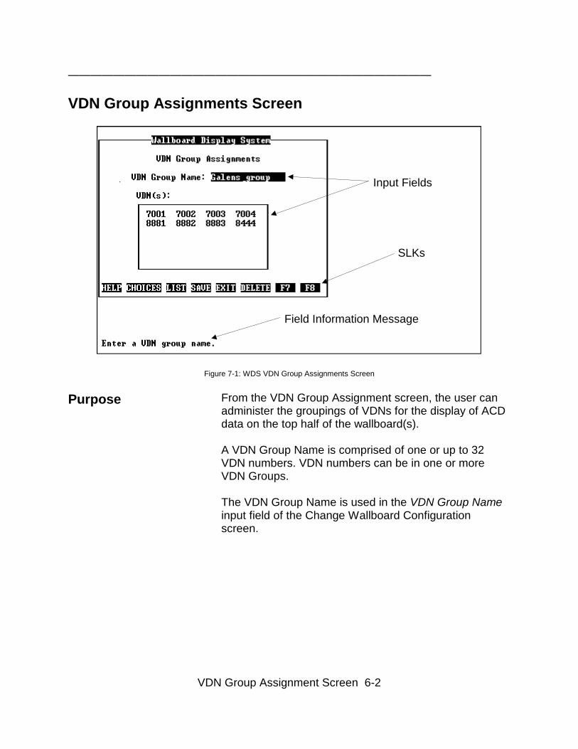
VDN Group Assignments Screen
Field Information Message
SLKs
Input Fields
Figure 7-1: WDS VDN Group Assignments Screen
Purpose From the VDN Group Assignment screen, the user canadminister the groupings of VDNs for the display of ACDdata on the top half of the wallboard(s).
A VDN Group Name is comprised of one or up to 32VDN numbers. VDN numbers can be in one or moreVDN Groups.
The VDN Group Name is used in the VDN Group Nameinput field of the Change Wallboard Configurationscreen.
VDN Group Assignment Screen 6-3
————————————————————————————————
Creating and Storing VDN Groups
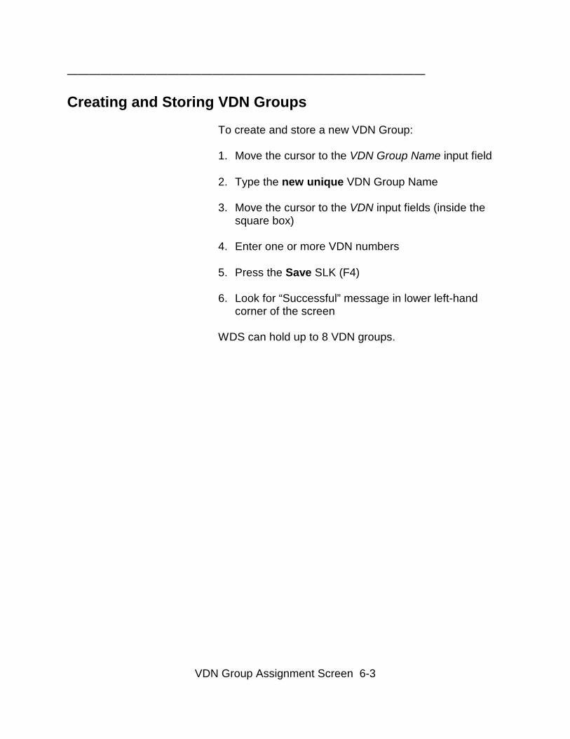
To create and store a new VDN Group:
1. Move the cursor to the VDN Group Name input field 2. Type the new unique VDN Group Name
3. Move the cursor to the VDN input fields (inside thesquare box)
4. Enter one or more VDN numbers 5. Press the Save SLK (F4) 6. Look for “Successful” message in lower left-hand
corner of the screen
WDS can hold up to 8 VDN groups.
VDN Group Assignment Screen 6-4
————————————————————————————————
Deleting VDN Groups
To delete a stored VDN Group:
NOTE: Deleting a VDN group will delete ALL the VDN(s)associated with the VDN group.
1. Move the cursor to the VDN Group Name input field
2. Press the Choices SLK (F2) 3. Move the cursor to the VDN Group Name to be
deleted by the arrow key 4. Press Enter/Return 5. Press the Delete SLK (F6) 6. Look for “Successful” message in lower left-hand
corner of the screen
VDN Group Assignment Screen 6-5
————————————————————————————————
Changing VDN Groups
To change VDNs associated with a VDN Group Name:
1. Move the cursor to the VDN Group Name input field
2. Press the Choices SLK (F2)
3. Move the cursor to the VDN Group Name to bechanged by the arrow key
4. Press Enter/Return
5. Move the cursor to the VDN input fields (inside thesquare box)
6. Enter or delete the desired VDN numbers 7. Press the Save SLK (F4)Look for “Successful” message in lower left-hand cornerof the screen
To change VDN Group Name associated with VDNnumbers:
1. Move the cursor to the VDN Group Name input field
2. Press the Choices SLK (F2)
3. Move the cursor to the VDN Group to be changed bythe arrow key
4. Press Enter/Return
5. Press the List SLK (F3)
6. Enter a new unique VDN Group name
7. Press the Save SLK (F4)Look for “Successful” message in lower left-hand cornerof the screen
VDN Group Assignment Screen 6-6
————————————————————————————————
Listing VDNs in a VDN Group
To List the VDNs that are associated with a VDN GroupName:
1. Move the cursor to the VDN Group Name input field
2. Press the Choices SLK (F2)
3. Move the cursor to the VDN Group to be listed by thearrow key
4. Press Enter/Return
5. Press the List SLK (F3) 6. Look for “Successful” message in lower left-hand
corner of the screen
VDN Group Assignment Screen 6-7
————————————————————————————————
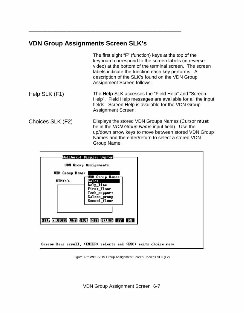
VDN Group Assignments Screen SLK’s
The first eight “F” (function) keys at the top of thekeyboard correspond to the screen labels (in reversevideo) at the bottom of the terminal screen. The screenlabels indicate the function each key performs. Adescription of the SLK’s found on the VDN GroupAssignment Screen follows:
Help SLK (F1) The Help SLK accesses the “Field Help” and “ScreenHelp”. Field Help messages are available for all the inputfields. Screen Help is available for the VDN GroupAssignment Screen.
Choices SLK (F2) Displays the stored VDN Groups Names (Cursor mustbe in the VDN Group Name input field). Use theup/down arrow keys to move between stored VDN GroupNames and the enter/return to select a stored VDNGroup Name.
Figure 7-2: WDS VDN Group Assignment Screen Choices SLK (F2)
VDN Group Assignment Screen 6-8
————————————————————————————————
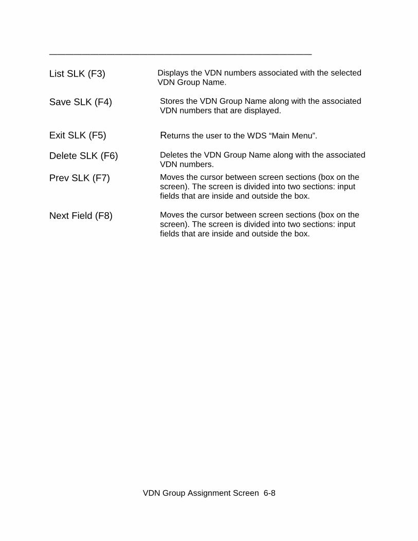
List SLK (F3) Displays the VDN numbers associated with the selectedVDN Group Name.
Save SLK (F4) Stores the VDN Group Name along with the associatedVDN numbers that are displayed.
Exit SLK (F5) Returns the user to the WDS “Main Menu”.
Delete SLK (F6) Deletes the VDN Group Name along with the associatedVDN numbers.
Prev SLK (F7)
Next Field (F8)
Moves the cursor between screen sections (box on thescreen). The screen is divided into two sections: inputfields that are inside and outside the box.
Moves the cursor between screen sections (box on thescreen). The screen is divided into two sections: inputfields that are inside and outside the box.

Start/Stop Wallboard Display Screen 7-1
————————————————————————————————
General InformationThis chapter explains the Start/Stop Wallboard Displayscreen. From this screen the execution of all wallboardscan be started or stopped.
Start/Stop Wallboard Display Screen 7-2
————————————————————————————————
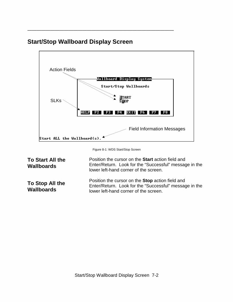
Start/Stop Wallboard Display Screen
Field Information Messages
SLKs
Action Fields
Figure 8-1: WDS Start/Stop Screen
To Start All theWallboards
To Stop All theWallboards
Position the cursor on the Start action field andEnter/Return. Look for the “Successful” message in thelower left-hand corner of the screen.
Position the cursor on the Stop action field andEnter/Return. Look for the “Successful” message in thelower left-hand corner of the screen.

Start/Stop Wallboard Display Screen 7-3
————————————————————————————————
Start/Stop Wallboard Display Screen SLK’s
The first eight “F” (function) keys at the top of thekeyboard correspond to the screen labels (in reversevideo) at the bottom of the terminal screen. The screenlabels indicate the function each key performs. Adescription of the SLK’s found on the WallboardMessage Screen follows:
Help SLK (F1) The Help SLK accesses the “Field Help” and “ScreenHelp”. Field Help messages are available for all theaction fields. Screen Help is available for the Start/StopWallboard Display Screen.
No Function (F2) No action performed.
No Function (F3) No action performed.
No Function (F4) No action performed.
Exit SLK (F5) Returns the user to the WDS “Main Menu”.
No Function (F6) No action performed.
Previous Field (F7) Moves the cursor to the previous field.
Next Field (F8) Moves the cursor to the next field.

Configuration Guidelines A-1
————————————————————————————————
General Information
In order to keep the CMS system responsive, theaverage CPU occupancy should be limited to about 60%.Assuming that miscellaneous activities (e.g. starting upnew reports, scrolling, administration, etc.) will consumeabout 10%, this leaves an occupancy of about 50%.
This section present tools and guidelines to the user fordetermining a recommended refresh rate and amaximum configuration for the WDS software in anactive CMS environment.
Determining Refresh Rates for the WDS A-2
————————————————————————————————
Determining Refresh Rates for the WDS
The program Realtime can be used to determine theappropriate refresh for all realtime reports and the WDSsoftware.
Using the RealtimeRefresh Program
The Realtime program is distributed with the CMSsystem. The program calculates the best (shortest)refresh rates a user can get in CMS real-time reports andthe WDS software. The program bases its calculationson a selected computer and the configuration and use ofthe CMS.
Note: Use this program only if the user wants to knowthe shortest possible refresh rate.
Options of the Real-time Refresh Program
The program gives you two basic options for findingrefresh rates:
• Different PeriodsThe program finds the best possible refresh rate foreach type of report. The best refresh rate for one typeof report will normally differ from the best rate foranother type of report.
• Single Period
The program finds one best refresh rate that appliesto all reports that are running. For this option, youmust specify the exact number of reports of each typethat will be running simultaneously.
Determining Refresh Rates for the WDS A-3
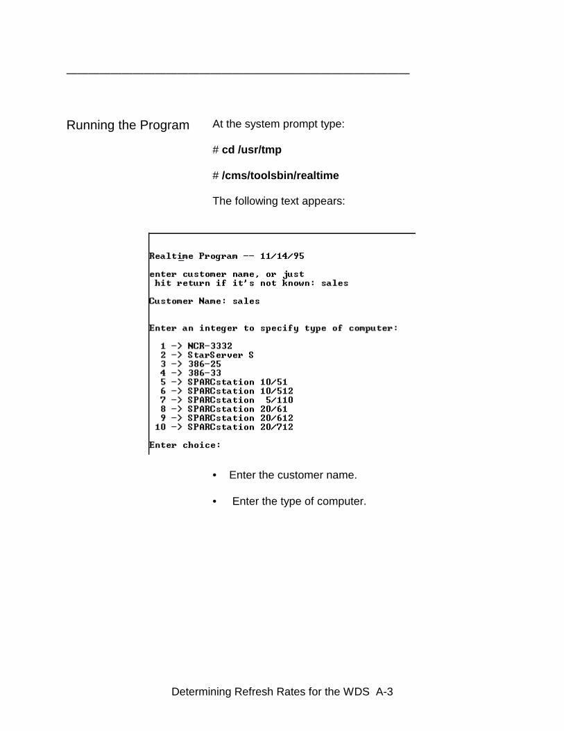
——————————————————————————————— Running the Program
At the system prompt type: # cd /usr/tmp # /cms/toolsbin/realtime The following text appears:
• Enter the customer name.
• Enter the type of computer.
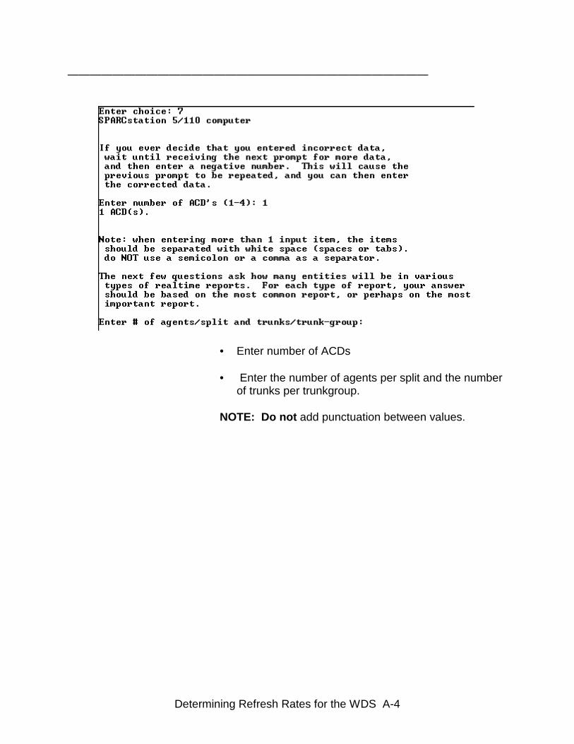
Determining Refresh Rates for the WDS A-4
————————————————————————————————
• Enter number of ACDs
• Enter the number of agents per split and the numberof trunks per trunkgroup.
NOTE: Do not add punctuation between values.
Determining Refresh Rates for the WDS A-5
————————————————————————————————
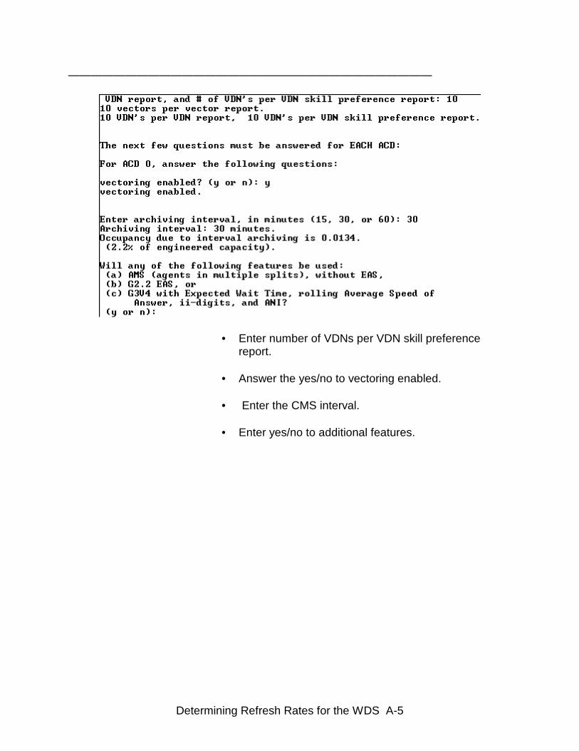
• Enter number of VDNs per VDN skill preference
report. • Answer the yes/no to vectoring enabled. • Enter the CMS interval.
• Enter yes/no to additional features.
Determining Refresh Rates for the WDS A-6
————————————————————————————————
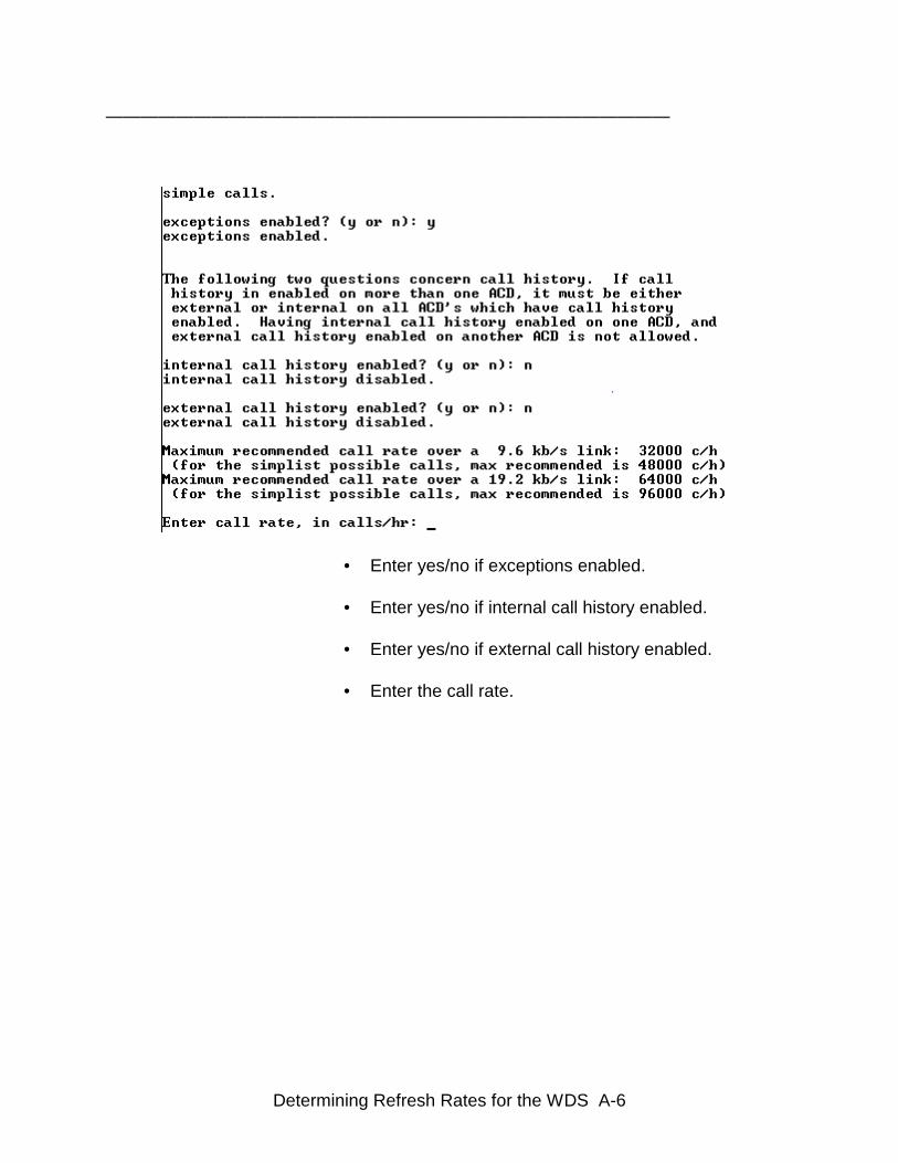
• Enter yes/no if exceptions enabled. • Enter yes/no if internal call history enabled. • Enter yes/no if external call history enabled. • Enter the call rate.
Determining Refresh Rates for the WDS A-7
————————————————————————————————
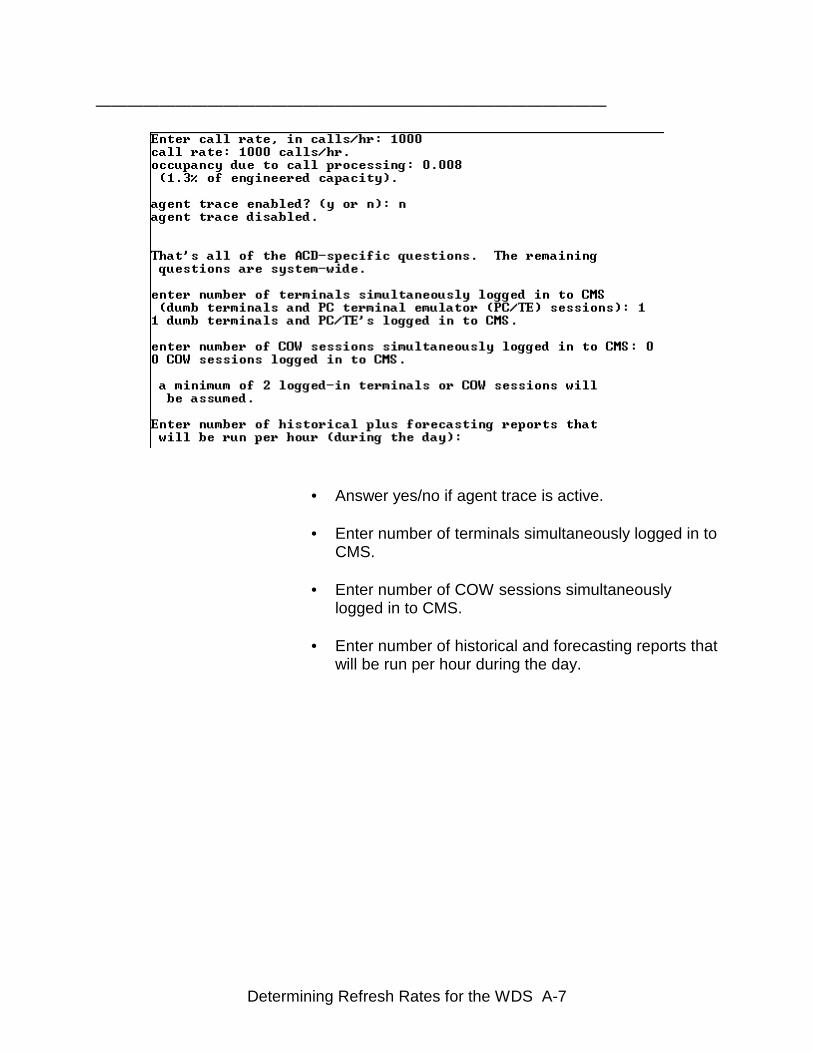
• Answer yes/no if agent trace is active. • Enter number of terminals simultaneously logged in to
CMS. • Enter number of COW sessions simultaneously
logged in to CMS. • Enter number of historical and forecasting reports that
will be run per hour during the day.

Determining Refresh Rates for the WDS A-8
————————————————————————————————
• Enter the number of historical reports that are active.
• Enter 1 for period choice. • Add 4 to the to the average number of running
realtime reports for the split data installation of WDSsoftware and enter the total.
OR• Add 8 to the to the average number of running
realtime reports for the split data installation of WDSsoftware with the historical feature turned on andenter the total.
OR• Add 8 to the to the average number of running
realtime reports for the VDN data installation of WDSsoftware and enter the total.
OR• Add 16 to the to the average number of running
realtime reports for the VDN data installation of WDSsoftware with the historical feature turned on andenter the total.
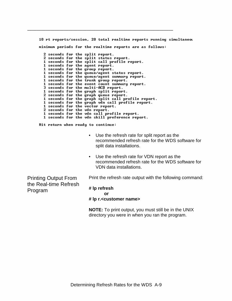
Determining Refresh Rates for the WDS A-9
————————————————————————————————
• Use the refresh rate for split report as therecommended refresh rate for the WDS software forsplit data installations.
• Use the refresh rate for VDN report as the
recommended refresh rate for the WDS software forVDN data installations.
Printing Output Fromthe Real-time RefreshProgram
Print the refresh rate output with the following command: # lp refresh or # lp r.<customer name> NOTE: To print output, you must still be in the UNIXdirectory you were in when you ran the program.
Maximum WDS Configuration and Refresh Rate A-10
————————————————————————————————
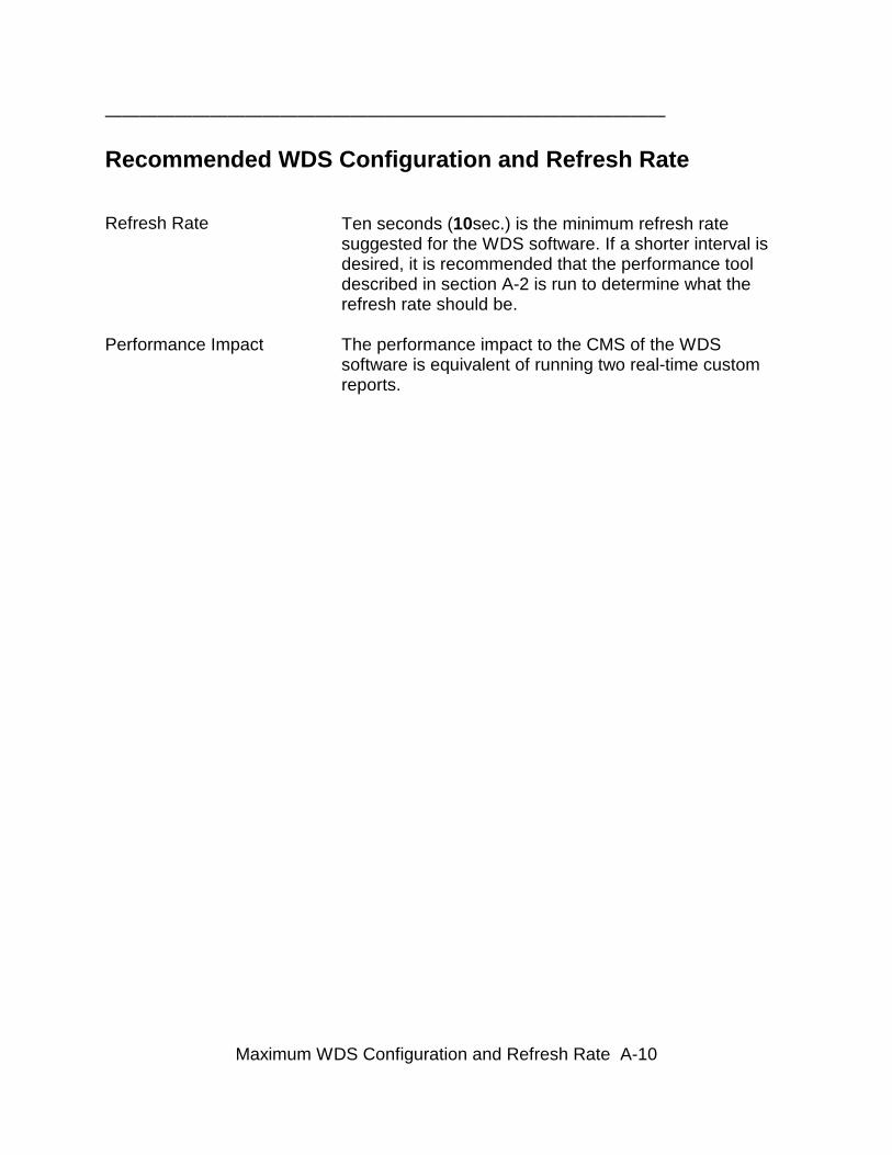
Recommended WDS Configuration and Refresh Rate
Refresh Rate Ten seconds (10sec.) is the minimum refresh ratesuggested for the WDS software. If a shorter interval isdesired, it is recommended that the performance tooldescribed in section A-2 is run to determine what therefresh rate should be.
Performance Impact The performance impact to the CMS of the WDSsoftware is equivalent of running two real-time customreports.
On-Line Help Subsystem B-1
————————————————————————————————
General Information
This section expands upon the information about theHelp Subsystem covered in previous chapters.
This appendix details:
• Accessing the Help Subsystem • Sizing the Help Subsystem • Navigating the Help Screens
On-Line Help Subsystem B-2
————————————————————————————————
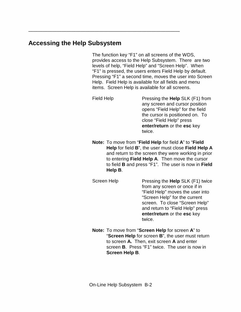
Accessing the Help Subsystem
The function key “F1” on all screens of the WDS,provides access to the Help Subsystem. There are twolevels of help, “Field Help” and “Screen Help”. When“F1” is pressed, the users enters Field Help by default.Pressing “F1” a second time, moves the user into ScreenHelp. Field Help is available for all fields and menuitems. Screen Help is available for all screens.
Field Help Pressing the Help SLK (F1) fromany screen and cursor positionopens “Field Help” for the fieldthe cursor is positioned on. Toclose “Field Help” pressenter/return or the esc keytwice.
Note: To move from “Field Help for field A” to “Field Help for field B”, the user must close Field Help Aand return to the screen they were working in priorto entering Field Help A. Then move the cursor to field B and press “F1”. The user is now in FieldHelp B.
Screen Help Pressing the Help SLK (F1) twicefrom any screen or once if in“Field Help” moves the user into“Screen Help” for the currentscreen. To close “Screen Help”and return to “Field Help” pressenter/return or the esc keytwice.
Note: To move from “Screen Help for screen A” to “Screen Help for screen B”, the user must return to screen A. Then, exit screen A and enter screen B. Press “F1” twice. The user is now in Screen Help B.
On-Line Help Subsystem B-3
————————————————————————————————
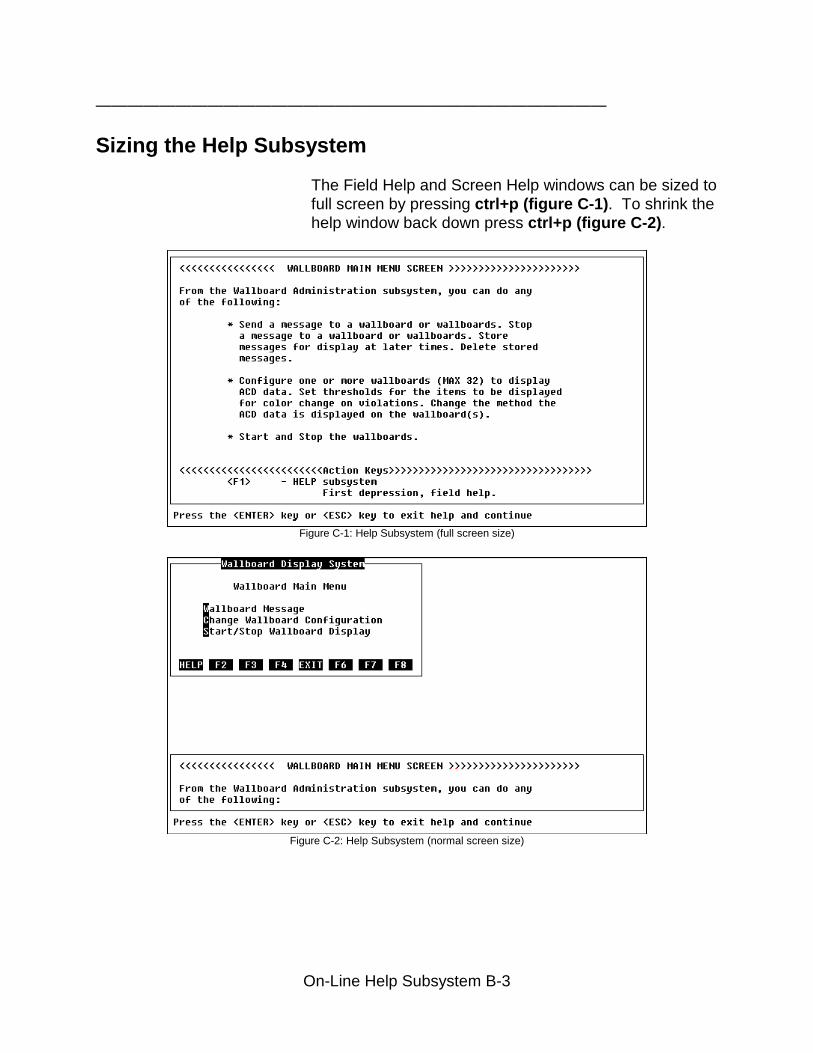
Sizing the Help Subsystem
The Field Help and Screen Help windows can be sized tofull screen by pressing ctrl+p (figure C-1). To shrink thehelp window back down press ctrl+p (figure C-2).
Figure C-1: Help Subsystem (full screen size)
Figure C-2: Help Subsystem (normal screen size)
————————————————————————————————
Moving in the Help Screens
If there is more information than the help screen candisplay, the Up Arrow and Down Arrow allow the userto scroll through the information. The Down Arrow movesthe cursor down one line per depression. The Up Arrowmoves the cursor up one line per depression. Or, theuser can hold down either arrow key to move multiplelines in the direction of the depressed arrow.
On-Line Help Subsystem B-4
————————————————————————————————
General Information
This section presents a flowchart to assist in thediagnosis and resolution of commonly encounteredproblems in the Wallboard Display System.
The process to reset a single wallboard port is alsocovered in this appendix.
This appendix assumes some familiarity with UNIX onthe part of the administrator and is not intended toreplace qualified professional assistance.
Troubleshooting C-1
Troubleshooting C-2
————————————————————————————————
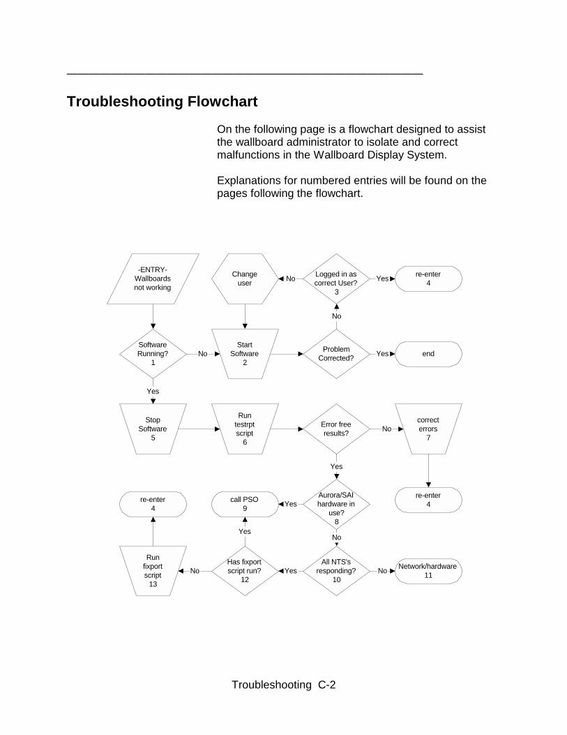
Troubleshooting Flowchart
On the following page is a flowchart designed to assistthe wallboard administrator to isolate and correctmalfunctions in the Wallboard Display System.
Explanations for numbered entries will be found on thepages following the flowchart.
-ENTRY-Wallboardsnot working
SoftwareRunning?
1
StartSoftware
2
ProblemCorrected? end
Logged in ascorrect User?
3
Changeuser
StopSoftware
5
Runtestrptscript
6
Error freeresults?
correcterrors
7
re-enter4
Aurora/SAIhardware in
use?8
All NTS'sresponding?
10
Network/hardware11
Has fixportscript run?
12
call PSO9
Runfixportscript
13
re-enter4
No
No
re-enter4No
Yes
Yes
Yes
No
Yes
NoYes
Yes
No
Yes
No
Troubleshooting C-3
————————————————————————————————
Flowchart Items Explained
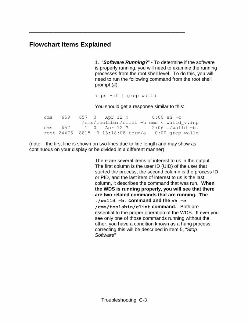
1. “Software Running?” - To determine if the softwareis properly running, you will need to examine the runningprocesses from the root shell level. To do this, you willneed to run the following command from the root shellprompt (#):
# ps –ef | grep walld
You should get a response similar to this:
cms 659 657 0 Apr 12 ? 0:00 sh -c /cms/toolsbin/clint -u cms <.walld_v.inp cms 657 1 0 Apr 12 ? 2:06 ./walld -b. root 24476 8815 0 13:18:08 term/a 0:00 grep walld
(note – the first line is shown on two lines due to line length and may show ascontinuous on your display or be divided in a different manner)
There are several items of interest to us in the output.The first column is the user ID (UID) of the user thatstarted the process, the second column is the process IDor PID, and the last item of interest to us is the lastcolumn, it describes the command that was run. Whenthe WDS is running properly, you will see that thereare two related commands that are running. The./walld –b. command and the sh –c/cms/toolsbin/clint command. Both areessential to the proper operation of the WDS. If ever yousee only one of those commands running without theother, you have a condition known as a hung process,correcting this will be described in item 5, “StopSoftware”
Troubleshooting C-4
2. “Start Software” – There are two methods to properlystart the WDS software. The first is the methoddescribed in Chapter 7, where the software is startedfrom the menu. This is the generally preferred methodand should be used whenever possible. Another methodto start the software is from the command line and isincluded here for ease of trouble shooting. Ensure thatyou are logged in as the proper UID for the WDSadministrator and that you are in the WDS main directory( /export/home/pserv/walld is correct in mostcases.) Execute the command: $ ./startwalldAfter a short pause, the prompt should return and thesoftware should be running (refer to item 1 to ensure thatit is.)
3. “Logged in as correct User?” – It is therecommended practice that there be a single User IDfor the administration of the WDS software. Multipleusers accessing the software at the same time maycause difficulties to arise in the operation of the software.Certain users will have limited resources that will affectthe operation of the software as well. For the purposeof troubleshooting, ensure that no other users areattempting to use the WDS, and that the UID you areusing to start and stop the software is that which hasbeen approved by your organization as the WDSadministrator. You may use the CMS User ID, but thatmay not recreate conditions that arise if another UID isroutinely used for WDS administration.
4. “Re-enter” – At several stages during the troubleshooting, as conditions are eliminated, it will benecessary to re-start the flow chart process from thebeginning.
Troubleshooting C-5
5. “Stop Software” - In order to work from a commonbase line, it will be necessary to stop the software toreturn it to a known state. There are several methodsavailable to stop the software and each method hascertain advantages and drawbacks. The first method isto use the Stop/Start entry from the WDS menu. It issimple to use, but under certain circumstances, may notwork. The second method available is to execute theshell command:$ /export/home/pserv/walld/stopwalldNotice that this command is issued from the WDSadministrator user ID prompt, NOT the root shell prompt.This method is slightly more difficult, and works under thesame conditions as the menu access method, butwithout having to leave the shell environment. The finalmethod of stopping the software involves using theprocess table method as described in item 1,(# ps –ef|grep walld) to determine the Process IDof the wallboard software. After running the command asthe root user, locate the PID’s of all processes that arerelated to wallboards and run the following command,again from the root shell prompt (#):
# kill –9 657 659
(note: I have used the PID’s from the command outputlisted in item 1 for example only)
It is of the utmost importance that the PID’s beentered exactly as found in the output of the grepcommand. Typo’s or other errors could lead to thetermination of system critical processes and damageto the CMS system as a whole.
This method of halting the software will always work,regardless of original process owner, or other factors thatprevent the first two described methods from successfulexecution. It is also the method that opens the possibilityof severe system damage in the event of an error.Because of this possibility, it is the least preferredmethod except for experienced system administrators.
Troubleshooting C-6
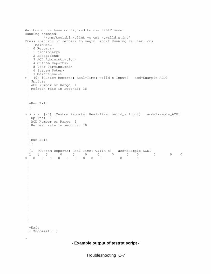
6. “Run testrpt script” – The software as installed,includes several trouble shooting tools. The first is thetestrpt script. This script, when run, simulates theWDS software accessing the CMS to retrieve data. Inorder for this tool to work properly, it must be run fromthe WDS directory, (/export/home/pserv/walld)and as the WDS administrator UID. Once theseconditions are met, execute the command:$ ./testrptThis will launch the script and produce an output similarto the example on the following page. Once you havethe output on the screen, press the delete key toterminate the script, if not, it will run again after a shortpause. The script will read the configuration files andthen pass the information on to the CMS to gather thecorrect data. In the example output, you will see that thelast two lines of text read “exit successful.” This is yourindication that the CMS and the WDS software areworking together properly. If you should see “exit failed”then there should also be a brief explanation of thefailure in the text output. These error messages are vitalto the correction of the software and should be noted forreferral at later steps in the trouble shooting process.
7. ”Correct errors” – Once you have determined thatthere are errors in the configuration files, it will benecessary to correct them. Experienced administratorsmay be familiar with the error codes to an extent suchthat they may make the corrections themselves, but dueto the large number of variations of configurations andpossible messages, it is beyond the scope of thisdocument to go into significant detail here. Therefore,WDS administrators are strongly encouraged to contactLucent Technologies PSO as outlined on page 1-3 tomake the required corrections and continue with thetrouble shooting.
Troubleshooting C-7
Wallboard has been configured to use SPLIT mode.Running command: “/cms/toolsbin/clint –u cms <.walld_s.inp”Press <return> or <enter> to begin report Running as user: cms
� MainMenu | 0 Reports> | 1 Dictionary> | 2 Exceptions> | 3 ACD Administration> | 4 Custom Reports> | 5 User Permissions> | 6 System Setup> | 7 Maintenance>> |(0) [Custom Reports: Real-Time: walld_s Input] acd=Example_ACD1 | Splits: | ACD Number or Range 1 | Refresh rate in seconds: 18 | | | |+Run,Exit |{}
> > > > |(0) [Custom Reports: Real-Time: walld_s Input] acd=Example_ACD1 | Splits: 1 | ACD Number or Range 1 | Refresh rate in seconds: 10 | | | |+Run,Exit |{}
|(1) [Custom Reports: Real-Time: walld_s] acd=Example_ACD1 |1 1 0 0 0 0 0 0 0 0 0 0 00 0 0 0 0 0 0 0 0 0 0 0 | | | | | | | | | | | | | | | | | | |+Exit |{ Successful }
>
- Example output of testrpt script -
Troubleshooting C-8
8. “Aurora/SAI hardware in use?” - Onceconfiguration errors have been ruled out, it becomesnecessary to determine the hardware involved beforeproceeding to the next appropriate step. To keep thisdocument as easy to use as possible, hardware optionshave been kept simple. Your particular installation mayhave both local serial ports (SAI or Aurora) andnetworked serial ports (Network Terminal Server or NTS)but only installations with just networked serial ports canbe considered for further administrator trouble shooting.To determine if you have local serial port extensions(SAI/P or Aurora cards) in use by the WDS software, itwill be necessary to examine your current setup file. Theeasiest method for this is to enter into the '’changewallboard configuration'’ menu item from the WDS mainmenu. Once there, scan through the activeconfigurations for an entry in the ‘serial TTY device’ thatis of the /dev/term/XXXX format, where XXXX is aspecific port such as ‘a001’ or ‘07’. If any such entryexists, then your installation is using local serial portextensions, and no further trouble shooting is feasible atthe end user level.
9. “Call PSO” – The scope of this document is not todiagnose and correct every possible issue, but rather toincrease the efficiency and speed of repair, and toreduce costs incurred for maintenance. At several pointsin this flowchart, the limit of reasonable customeraction is reached and the WDS administrator isstrongly encouraged to follow the contact procedureoutlined on page 1-3.
Troubleshooting C-9
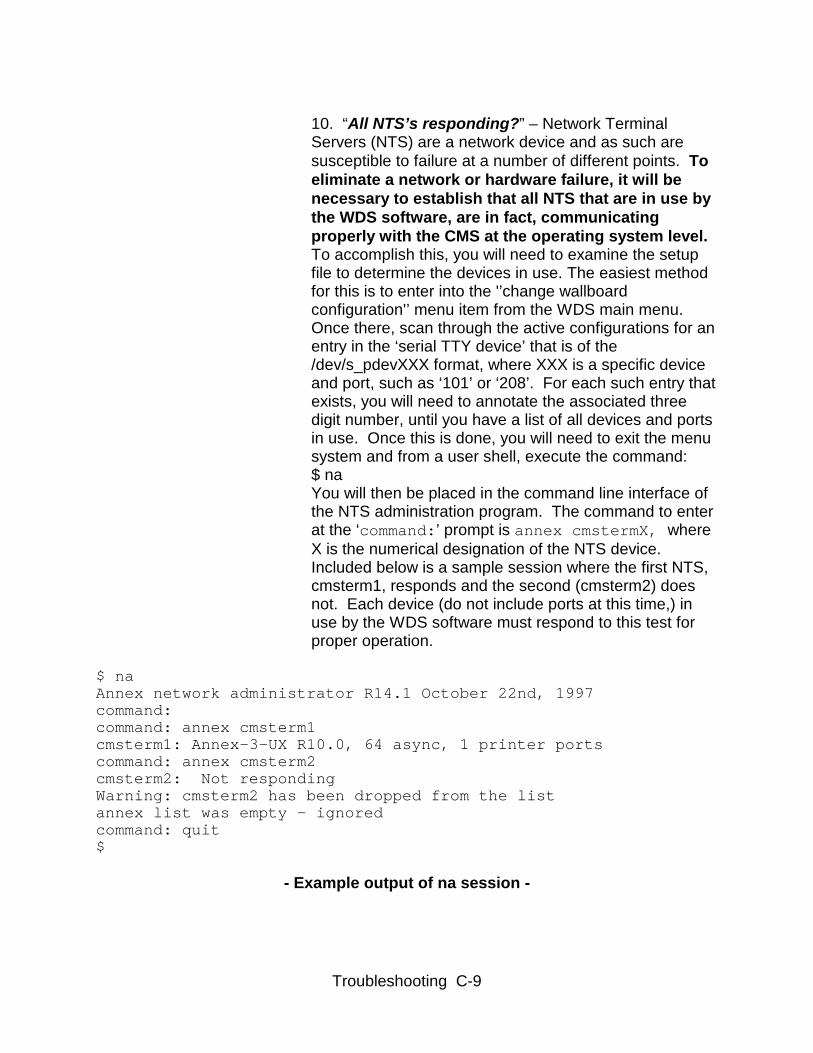
10. “All NTS’s responding?” – Network TerminalServers (NTS) are a network device and as such aresusceptible to failure at a number of different points. Toeliminate a network or hardware failure, it will benecessary to establish that all NTS that are in use bythe WDS software, are in fact, communicatingproperly with the CMS at the operating system level.To accomplish this, you will need to examine the setupfile to determine the devices in use. The easiest methodfor this is to enter into the '’change wallboardconfiguration'’ menu item from the WDS main menu.Once there, scan through the active configurations for anentry in the ‘serial TTY device’ that is of the/dev/s_pdevXXX format, where XXX is a specific deviceand port, such as ‘101’ or ‘208’. For each such entry thatexists, you will need to annotate the associated threedigit number, until you have a list of all devices and portsin use. Once this is done, you will need to exit the menusystem and from a user shell, execute the command:$ naYou will then be placed in the command line interface ofthe NTS administration program. The command to enterat the ‘command:’ prompt is annex cmstermX, whereX is the numerical designation of the NTS device.Included below is a sample session where the first NTS,cmsterm1, responds and the second (cmsterm2) doesnot. Each device (do not include ports at this time,) inuse by the WDS software must respond to this test forproper operation.
$ naAnnex network administrator R14.1 October 22nd, 1997command:command: annex cmsterm1cmsterm1: Annex-3-UX R10.0, 64 async, 1 printer portscommand: annex cmsterm2cmsterm2: Not respondingWarning: cmsterm2 has been dropped from the listannex list was empty - ignoredcommand: quit$
- Example output of na session -

Troubleshooting C-10
11. “Network/Hardware” – If any one of the NTShardware in use by the WDS software does not respondto the na application as outlined in item 10, then there issome difficulty at the hardware or network level. TheCMS helpline and your own IT or networkadministration departments are the best resourcesavailable to resolve this issue.
12. “Has fixport script run?” – If you have already runthe fixport script as outlined in the following section,then no further trouble shooting is feasible at the enduser level.
13. “Run fixport script” – See ‘Reset Wallboard Port’in the next section for details.
Troubleshooting C-11
————————————————————————————————
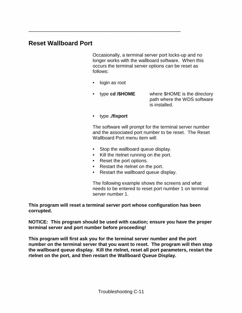
Reset Wallboard Port
Occasionally, a terminal server port locks-up and nolonger works with the wallboard software. When thisoccurs the terminal server options can be reset asfollows:
• login as root • type cd /$HOME where $HOME is the directory
path where the WDS softwareis installed.
• type ./fixport The software will prompt for the terminal server numberand the associated port number to be reset. The ResetWallboard Port menu item will: • Stop the wallboard queue display.• Kill the rtelnet running on the port.• Reset the port options.• Restart the rtelnet on the port.• Restart the wallboard queue display.
The following example shows the screens and whatneeds to be entered to reset port number 1 on terminalserver number 1.
This program will reset a terminal server port whose configuration has beencorrupted.
NOTICE: This program should be used with caution; ensure you have the properterminal server and port number before proceeding!
This program will first ask you for the terminal server number and the portnumber on the terminal server that you want to reset. The program will then stopthe wallboard queue display. Kill the rtelnet, reset all port parameters, restart thertelnet on the port, and then restart the Wallboard Queue Display.
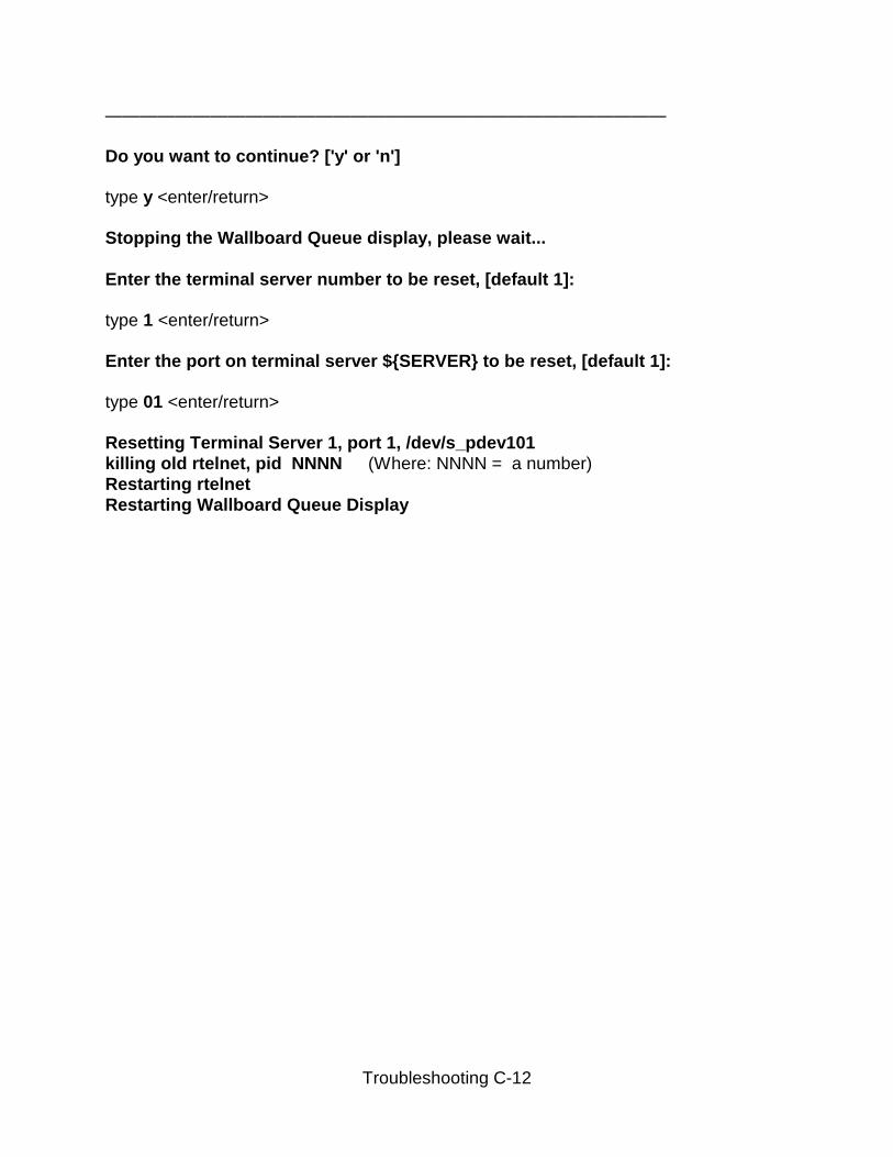
Troubleshooting C-12
————————————————————————————————
Do you want to continue? ['y' or 'n']
type y <enter/return>
Stopping the Wallboard Queue display, please wait...
Enter the terminal server number to be reset, [default 1]:
type 1 <enter/return>
Enter the port on terminal server ${SERVER} to be reset, [default 1]:
type 01 <enter/return>
Resetting Terminal Server 1, port 1, /dev/s_pdev101killing old rtelnet, pid NNNN (Where: NNNN = a number)Restarting rtelnetRestarting Wallboard Queue Display