w walkera G-30 Gimbal. User Manual G-3D Gimbal... · G-30 Gimbal. User Manual G-30 Gimbal is a...
6
• G-30 Gimbal . User Manual G-30 Gimbal is a high-precision and portable Gimbal specifically designed for ilook , ilook+ , GoPro series cameras by Walkera. Adopting aluminum alloy CNC precision machining, brushless motor drive, high accuracy intelligent electronic control system, it can be widely applied to film photography, advertising aerial photography etc. The highly precise and stable structure can ensure the aircraft accurately control the mounted camera to keep stable duri ng high-speed flying and take the best aerial photography pictures and videos. • Fixed screw(M3x12) -----' of Gimbal Gyro w walkera G-30 Contro ll er
Transcript of w walkera G-30 Gimbal. User Manual G-3D Gimbal... · G-30 Gimbal. User Manual G-30 Gimbal is a...
•
G-30 Gimbal. User Manual G-30 Gimbal is a high-precision and portable Gimbal specifically
designed for ilook, ilook+, GoPro series cameras by Walkera .
Adopting aluminum alloy CNC precision machining, brushless
motor drive, high accuracy intelligent electronic control system,
it can be widely applied to film photography, advertising aerial
photography etc. The highly precise and stable structure can
ensure the aircraft accurately control the mounted camera to
keep stable during high-speed flying and take the best aerial
photography pictures and videos.
•
Fixed screw(M3x12)-----' of Gimbal
Gyro
w walkera
G-30 Controller

1.0 Features and Technical Parameters
(1) Support ilook, ilook+, GoPro series camera video auxi liary output.
(2) Support power supply voltage compensation.
(3) Support the motor drive end short circuit protection.
(4) Support initial tilt and roll angle custom .
(5) Support stick position mode and rate mode.
(6) Support regular receiver.
(7) Operating voltage: DC 7.4V-28V (recommended 12V, 3S lipo battery).
(8) Operating current: 500mA-600mA (depends on the voltage supplied and motor power) .
(9) Operating temperature: -15 C- 65 C .
(1 0) Sensor: 3-axis MEMS gyro and 3-axis MEMS accelerometer.
(11) Control accuracy : 0.02°.
(12) Angle control range: -135°-90° ( tilt )) -45°-45° ( roll ) .
(13) Applicable camera: ilook, il ook+, GoPro Series.
(14) Size: 114.3mm x 97.5mm x 106.6mm(L x W x H).
(15) Weight: 188g(Without camera).
(16) The controller program can be upgraded on Walkera website
(UP02 and UP02 adapter requested).
(1) When Gimbal is assembled with camera and meet
the Gimbal barycenter is unbalanced, assemble
Gimbal Balance Accessory is necessary.
(2) Please make sure the Gimbal equipped with
camera before power on, otherwise it will effect
the accuracy in calibration.
GJ
Tilt motor
Balance Accessory
3.1 Use 2 M3X8 screws to install the Gimbal fixing block into the bottom of the fuselage.
3.3 Fix the spring into M3x12 screw, then align the screw with the threaded hole and tighten to fix the Gimbal.
3.2 Align the Gimbal chute with the fixed block, then install it into the bottom of
fixing block in the direction of the arrow.
3.4 Install the camera to the Gimbal, fix it with the camera fixing frame (make sure the gap close to the lens), then use 2 M2X4
screws to tighten the camera fixing frame.
®-----,
@- - ___J
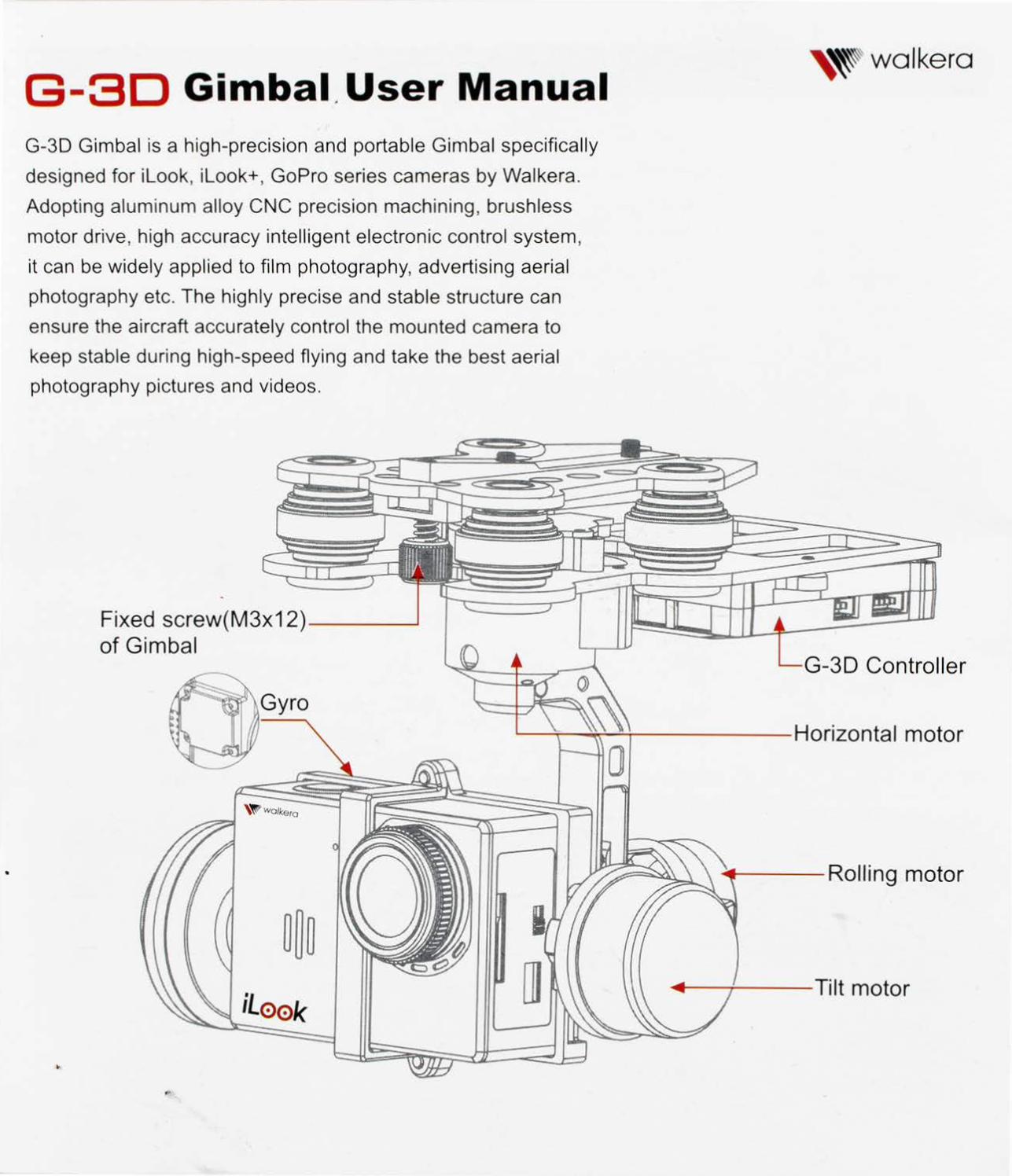
A. Connect aircraft power- - --...
B. Connect camera controller- --...
C1. Connect receiver 's tilt/roll -----, channel , control the tilt/roll of the gimbal
C2. Connect UP02, upgrade gimbal control system.
_ ___J
..-------®
,..-------0
ri---@
®
L----®
S/N G-30 Connector Function
1 Tilt motor connector(PIT) Connect with the tilt motor.
2 Roll ing motor connector(ROLL) Connect with the rolling motor.
3 Horizontal motor connector(YAW) Connect with the horizontal motor.
4 Gyro connector(GYRO) Connect with the gyro.
5 Sensor connector(SENCOR CON) Connect with the sensor.
6 Audio and video input I power output Audio and video input I power output. connector (AN IN/POWER OUTPUT)
7 Operating status indicator (G/RJB/Y) Operating status indication (green I red I blue I yellow light).
8 Function keys(FN) Function selection keys when enter into adjusting mode.
Power input I data connector Power input DC 7.4V-28V (recommended 12V, 3S lipo 9
(POWER INPUT/DATE CON) battery) I data connection.
Toggle switch( 1 ~ o) Switch between stick position mode (position 1)
10 and rate mode (position 0).
11 ROLL Knob AUX knob .
12 PIT Knob AUX knob.
5.1 Knob function
PIT Knob Adjusting tilt ang le(midpoint is 0°, angel range is -135°- 90°)
ROLL Knob Adjusting roll angle(midpoint is 0°, angel range is -45°- 45°)
5.2 Adjusting method
Put the gimbal on the horizontal position , initialization, red LED flash , initialization finished , green LED keeps solid , you can adjust the tilt and rolling angle according to the gimbal status.
(1 ) If you want the gimbal forward , please adjust the PIT knob in counterclockwise direction, and vice versa.
(2) If you want the gimballeftward , please adjust the ROLL knob in counterclockwise direction and vice versa. '
@)
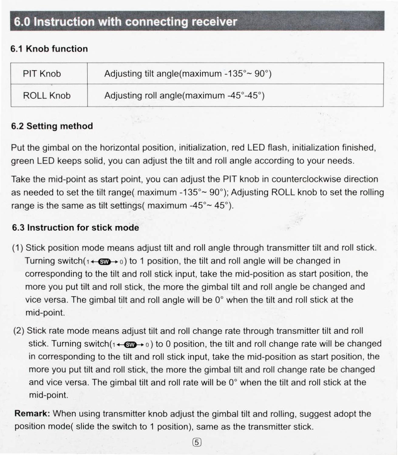
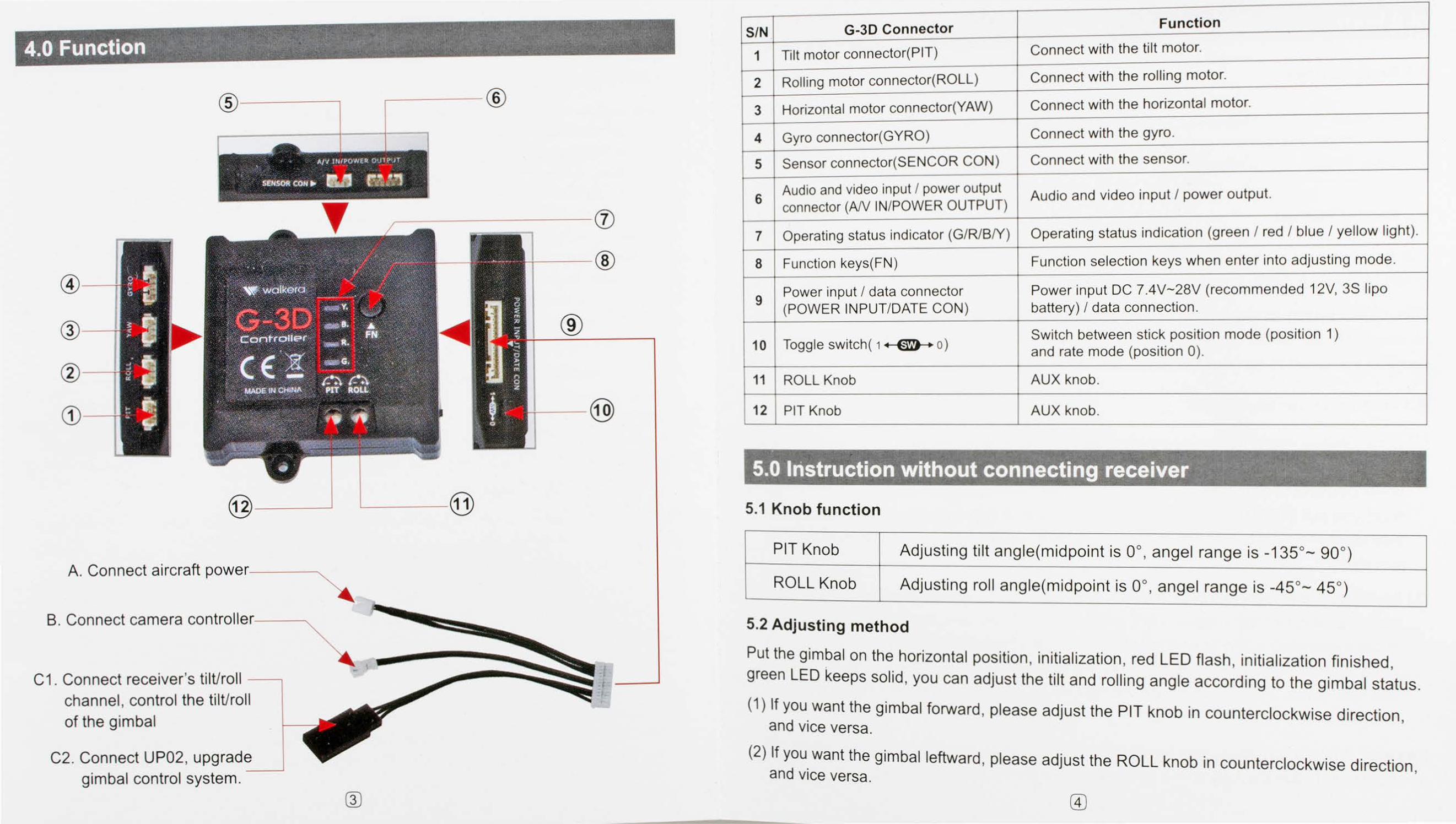
6.0 Instruction with connecting receiver
6.1 Knob function
PIT Knob Adjusting ti lt angle(maximum -135°- 90°)
ROLL Knob Adjusting roll angle( maximum -45° -45°)
• •
6.2 Setting method
Put the gimbal on the horizontal position , initialization, red LED flash , initialization finished ,
green LED keeps solid , you can adjust the tilt and roll angle according to your needs.
Take the mid-point as start point, you can adjust the PIT knob in counterclockwise di rection
as needed to set the tilt range( maximum -135°- 90°); Adjusting ROLL knob to set the rolling
range is the same as tilt settings( maximum -45°- 45°).
6.3 Instruction for stick mode
(1 ) Stick position mode means adjust tilt and roll angle through transmitter tilt and roll stick.
Turning switch( 1 ~ o) to 1 position, the tilt and rol l angle will be changed in
corresponding to the tilt and roll stick input, take the mid-position as start position, the
more you put ti lt and roll stick, the more the gimbal tilt and roll angle be changed and
vice versa. The gimbal tilt and roll angle will be oo when the tilt and roll stick at the .
mid-point.
(2) Stick rate mode means adjust tilt and roll change rate through transmitter tilt and roll
stick. Turning switch( 1 ~ o) to 0 position, the tilt and roll change rate will be changed
in corresponding to the ti lt and roll stick input, take the mid-position as start position, the
more you put tilt and roll stick, the more the gimbal ti lt and roll change rate be changed
and vice versa. The gimbal tilt and roll rate will be oo when the tilt and roll stick at the
mid-point.
Remark: When using transmitter knob adjust the gimbal tilt and rolling , suggest adopt the
position mode( slide the switch to 1 position), same as the transmitter stick.
®

7.0 Adjusting parameter mode instruction · ·. ·. .·· · _.- ._.. · . ·. · ·.
7.1 Knob function
PIT Knob Adjusting motor gain control.
ROLL Knob Adjusting motor output power.
7.2 Parameters adjustment principles
In the case of changing the camera on gimbal , adjust the parameters according to the load conditions. Under the same load conditions , when the motor output power increases, you must reduce the motor control gain . And when the motor output decreases, you can appropriately increase the control gain. Therefore, when the electrical power is enough , by reducing the motor power, you can get larger control gain and then get a better stabilization effect. But when the motor power is reduced , the gimbal's ability to resist the disturbance
will be reduced at the same time.
7.3 Adjustment methods
Put the gimbal in horizontal position. Power on and enter into the electricity initialization state . The red light flashes up first and then the green light will be constant after the red light passes through. Under this condition, you can enter the reference model to adjust gimbal parameters when it is necessary.
7 .3.1 Enter Into PAM Instructions
Press function key(FN) over 3 seconds, Red/Blue/Yellow LED flash quickly simultaneously indicating PAM entered.
7.3.2 Tilt motor output power and Gain Control Adjusting
(1) Enter into PAM, press function key(FN) once until red LED flashes quickly indicating tilt Motor Output Power and Gain Control Adjusting mode entered .
(2) Reset PIT/ROLL knob that means adjusting PIT/ROLL knob at middle position, blue/ yellow LED keep solid constantly.
(3) Please wait 3-5 seconds until red LED flashes slowly, then you can adjust the ti lt motor output power and gain control. CDTo increase the tilt motor output power, please adjust the ROLL knob clockwise properly and yellow LED flashing, and vice versa. @To increase the tilt motor gain , please adjust the PIT knob clockwise properly and blue LED flash ing and vice versa.
®
(4) Press function key(FN) triple until Green LED keeps solid , adjusting parameters will be
saved and exit PAM.
7 .3.3 Roll motor output power and Gain Control Adjusting
(1) Enter into PAM, press function key(FN) twice until blue LED flashes quickly indicating
roll motor output power and Gain Control Adjusting mode entered.
(2) Reset PIT/ROLL knob that means adjusting PIT/ROLL knob at middle position , red/
yellow LED keep solid constantly.
(3) Please wait 3-5 seconds until blue LED flashes slowly, then you can adjust the Roll motor
output power and gain control. Q)To increase the Roll motor output power, please adjust the ROLL knob clockwise properly and yellow LED flashing , and vice versa. @To increase
the Roll motor gain, please adjust the PIT knob clockwise properly and red LED flashing and vice versa.
(4) Press function key(FN) twice until Green LED keeps solid, adjusting parameters will be saved and exit PAM.
7.3.4 Horizontal motor output power and Gain Control Adjusting
(1 ) Enter into PAM, press function key(FN) triple until yellow LED flashes quickly indicating Horizontal motor output power and Gain Control Adjusting mode entered.
(2) Reset PIT/ROLL knob that means adjusting PIT/ROLL knob at middle position, red/blue LED keep solid constantly.
(3) Please wait 3-5 seconds until yellow LED flashes slowly, then you can adjust the Horizontal motor output power and gain control. CDTo increase the Horizontal motor output power, please adjust the ROLL knob clockwise properly and blue LED flashing , and vice versa. @To increase the Horizontal motor gain, please adjust the PIT knob clockwise properly and red LED flashing and vice versa.
(4) Press function key(FN) once until Green LED keeps solid , adjusting parameters will be saved and exit PAM .
7.3.5 Parameters save and PAM exit
Enter into PAM , Press function key(FN) four times until green LED keeps solid , adjusting parameters will be saved and exit PAM.
Remark: Please adjusting PIT/ROLL knob to middle position after PAM exit.
(ZJ
8.0 Adjusting parameter mode instruction
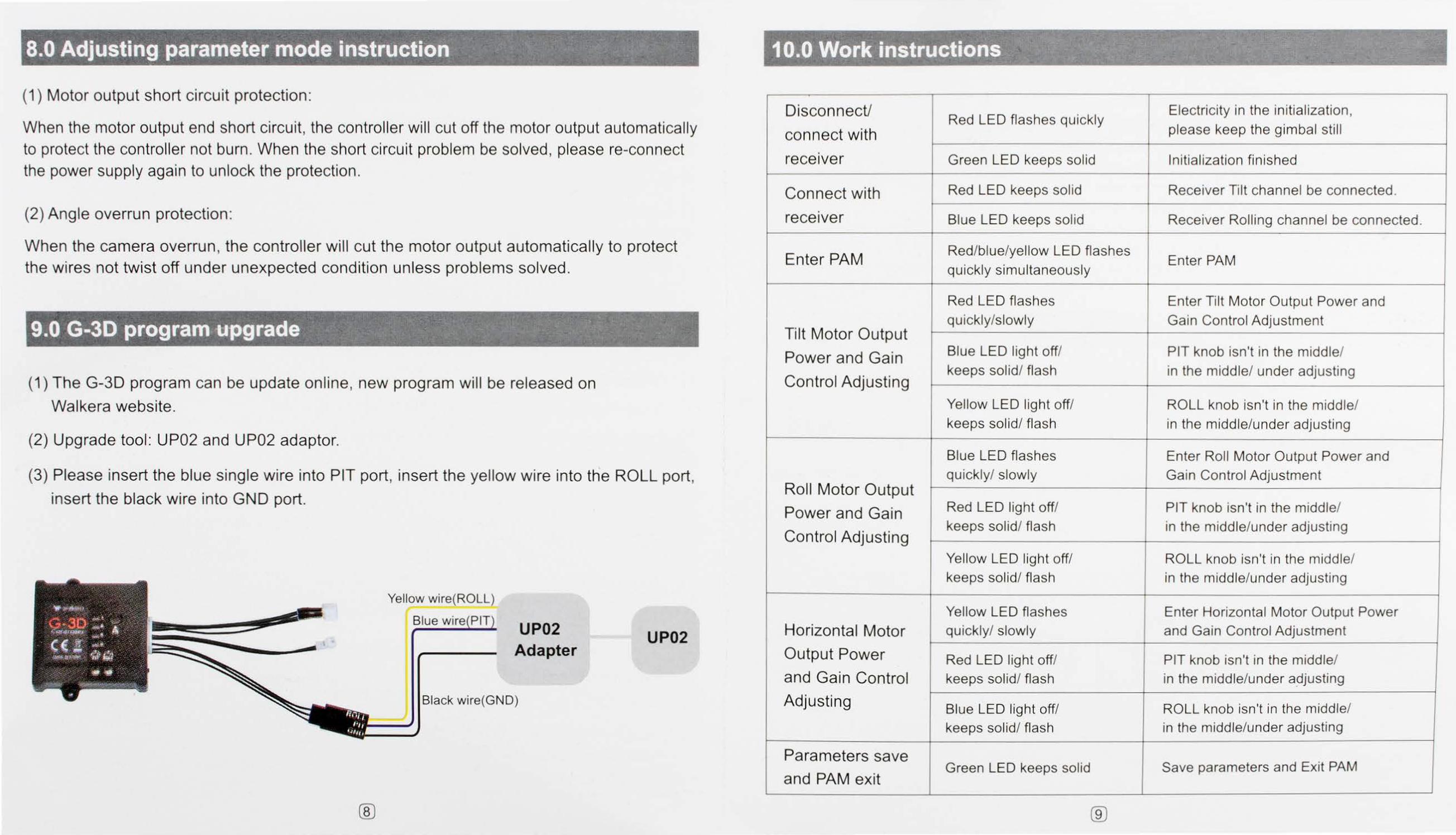
(1) Motor output short circuit protection :
When the motor output end short circuit, the controller will cut off the motor output automatically to protect the controller not burn . When the short circuit problem be solved , please re-connect the power supply again to unlock the protection .
(2) Angle overrun protection :
When the camera overrun , the controller wil l cut the motor output automatically to protect the wires not twist off under unexpected condition unless problems solved.
9.0 G-30 program upgrade · . ·
(1) The G-30 program can be update on line, new program will be released on
Walkera website.
(2) Upgrade tool: UP02 and UP02 adaptor.
(3) Please insert the blue single wire into PIT port, insert the yellow wire into the ROLL port,
insert the black wire into GND port.
®
Yellow wire(ROLL)
Blue wi UP02
Adapter
Black wi re(GND)
UP02
Disconnect/
connect with
rece1ver
Connect with
rece1ver
Enter PAM
Tilt Motor Output
Power and Gain
Control Adjusting
Roll Motor Output
Power and Gain
Control Adjusting
Horizontal Motor
Output Power
and Gain Control
Adjusting
Parameters save
and PAM exit
Red LED flashes quickly Electricity in the initialization, please keep the gimbal still
Green LED keeps solid Initialization finished
Red LED keeps solid Receiver Tilt channel be connected .
Blue LED keeps solid Receiver Rolling channel be connected .
Red/blue/yellow LED flashes Enter PAM
quickly simultaneously
Red LED flashes Enter Tilt Motor Output Power and quickly/slowly Gain Control Adjustment
Blue LED light off/ PIT knob isn't in the middle/ keeps solid/ flash in the middle/ under adjusting
Yellow LED light off/ ROLL knob isn't in the middle/ keeps solid/ flash in the middle/under adjusting
Blue LED flashes Enter Roll Motor Output Power and quickly/ slowly Gain Control Adjustment
Red LED light off/ PIT knob isn't in the middle/ keeps solid/ flash in the middle/under adjusting
Yellow LED light off/ ROLL knob isn't in the middle/ keeps sol id/ flash in the middle/under adjusting
Yellow LED flashes Enter Horizontal Motor Output Power quickly/ slowly and Gain Control Adjustment
Red LED light off/ PIT knob isn't in the middle/ keeps solid/ flash in the middle/under adjusting
Blue LED light off/ ROLL knob isn't in the middle/ keeps solid/ flash in the middle/under adjusting
Green LED keeps solid Save parameters and Exit PAM
®