TRANSPORTATION AND CLIMATE CHANGE IN VIRGINIA Transportation.

VIRGINIA DEPARTMENT OF TRANSPORTATION
STRUCTURE AND BRIDGE DIVISION
INSTRUCTIONAL AND INFORMATIONAL MEMORANDUM
GENERAL SUBJECT: Ancillary Structures
NUMBER: IIM-S&B-90.2 IIM-TE-382.1
SPECIFIC SUBJECT:
VDOT Guidelines to AASHTO Standard Specifications for Structural
Supports for Highway Signs, Luminaries, and Traffic Signals, 6th
Edition, 2013 with 2015 interims
Date: April 28, 2016
SUPERSEDES: IIM-S&B-90.1
DIVISION ADMINISTRATOR APPROVAL: /original signed/ /original signed/ Kendal R. Walus, P.E. Raymond J. Khoury, P.E. State Structure and Bridge Engineer State Traffic Engineer Approved: April 28, 2016 Approved: April 28, 2016
Changes are shaded.
The following VDOT Guidelines to the AASHTO Standard Specifications for Structural Supports for Highway Signs, Luminaires, and Traffic Signals, 6th Edition (LTS-6), 2013 with 2015 interims, are effective for projects as stated below. Effective Date: Future contracts: This Memorandum shall be effective for all contracts with an advertisement on or after July 1, 2016. Existing contracts: Requirements in this Memorandum may be applied under existing contracts (including existing Regional Traffic Signal Construction Contracts) if the change is approved by the Project Engineer. Land use permit for private developments: this Memorandum shall be effective for all projects where the design is submitted to VDOT on or after July 1, 2016. Design-Build or PPTA projects: this Policy shall be effective for projects with RFP released on or after July 1, 2016.

Instructional & Informational Memorandum IIM-S&B-90.2 Sheet 2 of 10
General Requirements: Variance from the VDOT Guidelines to these specifications shall require a Design Waiver. For complete information on and requirements of Design Waivers, see Section Pre.02 of Part 1 of the Manual of the Structure and Bridge Division. Any AASHTO Specification optional design parameter noted as “may be used at the discretion of the owner” that are not addressed in this document shall not be used for design. Square tube sign post, wood post, SSP-VA and SSP-VIA structures shall be provided in accordance with the requirements as shown in the VDOT Road and Bridge Standards. Lighting (conventional and high mast), signal (overhead, mast arm and span wire), pedestal poles, overhead (span, cantilever and butterfly) sign structures and ITS structures (camera poles, dynamic message signs (DMS), etc.) shall conform to the requirements of the AASHTO Standard Specifications for Structural Supports for Highway Signs, Luminaires, and Traffic Signals, 6th Edition (LTS-6), 2013 with 2015 interims with the following clarifications: SECTION 2: GENERAL FEATURES OF DESIGN: For additional requirements related to general features of design, see VDOT Road and Bridge Specifications, Section 700 and VDOT Road and Bridge Standards, Section 1300. See current IIM-S&B-89 for maximum span limits on ancillary structures and moratorium on bridge mounted sign structures. SECTION 3: LOADS: Wind Loading: (LTS-6 Article 3.8 and Appendix C) The alternate method for wind pressures provided in AASHTO Appendix C shall be used. Linear interpolation between wind contours is not permitted. The next higher contour shall be used for design. Reduced forces shall not be used for free swinging traffic signal and free swinging sign wind loadings. See Appendix A for wind maps of Virginia. For special wind regions in Bristol District shown on maps in Appendix A, the selection of the design wind speed shall consider localized effects. The minimum design wind speed for 50 year mean in these areas is 90 MPH, 25 year mean in these areas is 80 MPH and 10 year mean in these areas is 70 MPH. For bridge mounted structures/light poles and other site condition where structures may be elevated above the surrounding terrain, the height factor used shall be increased to account for the increased wind effects. (LTS-6 Article C.2) Wind speeds using 50-year mean recurrence shall be used for all conventional light poles, high mast light poles, ITS device support poles and overhead sign structures (span, cantilever and butterfly). Wind speeds using the 10-year mean recurrence shall be used for SSP-VA, SSP-VIA, square tube post and other ground mounted structures.

Instructional & Informational Memorandum IIM-S&B-90.2 Sheet 3 of 10
SECTION 3: LOADS: (cont’d) (LTS-6 Article C.2) Mast arm signal poles, mast arms, and strain poles shall be designed using the following wind speeds:
VDOT Traffic Operations Region
VDOT Districts Within That Region
Design Wind Speed for strain poles, mast arms, and mast arm
poles
Southwest Bristol, Salem, and
Lynchburg 70 MPH
Northwest Staunton and Culpeper 70 MPH Northern Northern Virginia 80 MPH
Central Richmond and Fredericksburg
80 MPH
Eastern Hampton Roads 90 MPH Mast arm signal pole and strain pole foundations shall be designed for wind speeds at the foundation location using the 25-year mean recurrence. SECTION 5: STEEL DESIGN: Laminated Structures: (LTS-6 Article C5.1) Laminated or multi-ply structures shall only be used in tapered sections. Holes and Cutouts (Unreinforced and Reinforced): (LTS-6 Article 5.14.5) The location and size of hand holes and cutouts shall be in accordance with the details as shown in the VDOT Road and Bridge Standards. For high mast light poles, the width of unreinforced and reinforced holes and cutouts in the cross-sectional plane of the tube shall not be greater than 50 percent of the tube diameter at that section. Welding: A connection detail using a full penetration groove weld with a backing ring may be considered for signal mast arms and high mast light poles. The backing ring shall be attached at the top and bottom face of the ring using a continuous fillet weld.
Instructional & Informational Memorandum IIM-S&B-90.2 Sheet 4 of 10
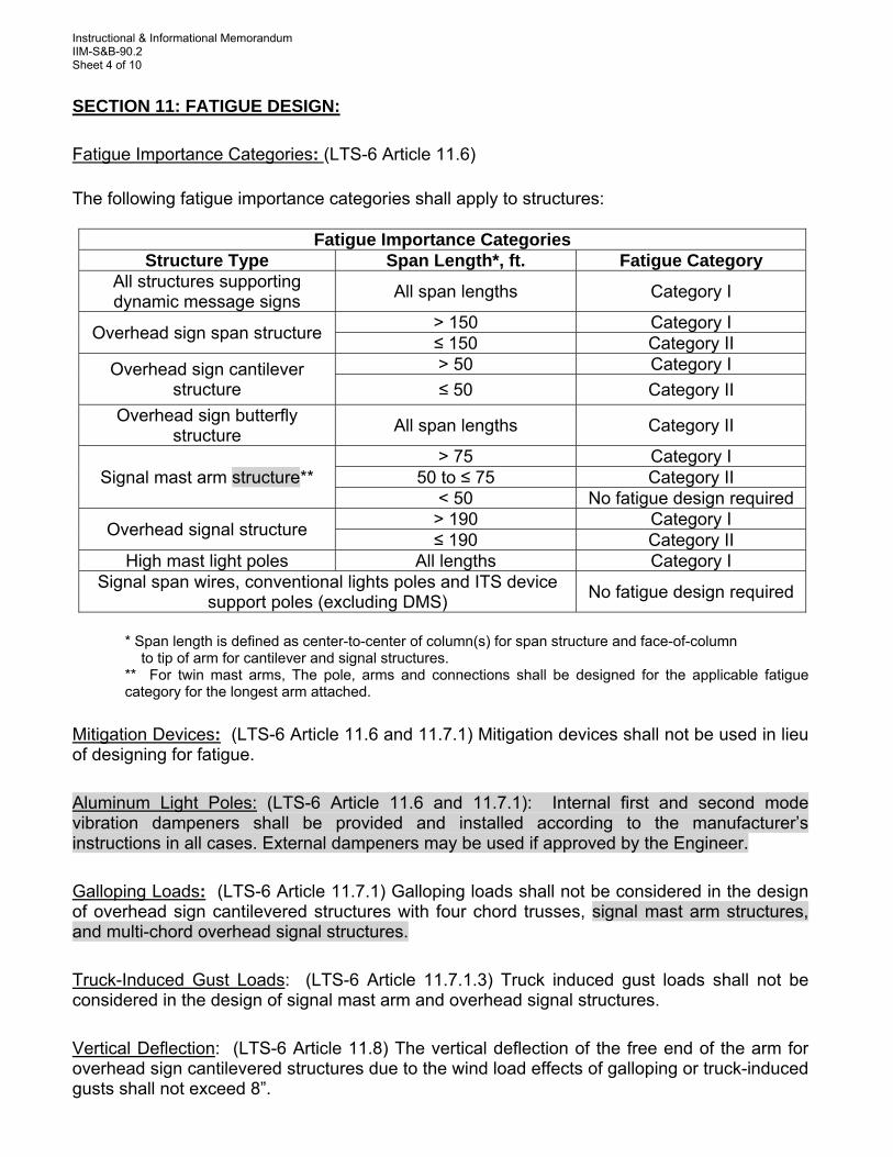
SECTION 11: FATIGUE DESIGN: Fatigue Importance Categories: (LTS-6 Article 11.6) The following fatigue importance categories shall apply to structures:
Fatigue Importance Categories
Structure Type Span Length*, ft. Fatigue Category All structures supporting dynamic message signs
All span lengths Category I
Overhead sign span structure > 150 Category I ≤ 150 Category II
Overhead sign cantilever structure
> 50 Category I
≤ 50 Category II
Overhead sign butterfly structure
All span lengths Category II
Signal mast arm structure** > 75 Category I
50 to ≤ 75 Category II < 50 No fatigue design required
Overhead signal structure > 190 Category I ≤ 190 Category II
High mast light poles All lengths Category I Signal span wires, conventional lights poles and ITS device
support poles (excluding DMS) No fatigue design required
* Span length is defined as center-to-center of column(s) for span structure and face-of-column to tip of arm for cantilever and signal structures. ** For twin mast arms, The pole, arms and connections shall be designed for the applicable fatigue category for the longest arm attached.
Mitigation Devices: (LTS-6 Article 11.6 and 11.7.1) Mitigation devices shall not be used in lieu of designing for fatigue. Aluminum Light Poles: (LTS-6 Article 11.6 and 11.7.1): Internal first and second mode vibration dampeners shall be provided and installed according to the manufacturer’s instructions in all cases. External dampeners may be used if approved by the Engineer. Galloping Loads: (LTS-6 Article 11.7.1) Galloping loads shall not be considered in the design of overhead sign cantilevered structures with four chord trusses, signal mast arm structures, and multi-chord overhead signal structures. Truck-Induced Gust Loads: (LTS-6 Article 11.7.1.3) Truck induced gust loads shall not be considered in the design of signal mast arm and overhead signal structures. Vertical Deflection: (LTS-6 Article 11.8) The vertical deflection of the free end of the arm for overhead sign cantilevered structures due to the wind load effects of galloping or truck-induced gusts shall not exceed 8”.

Instructional & Informational Memorandum IIM-S&B-90.2 Sheet 5 of 10
Section 13: FOUNDATION DESIGN: (This section provides guidance/modifications on the AASHTO Standard Specifications for Highway Bridges, 1996; 1997 and 1998 Interim Specifications as referenced in the AASHTO Standard Specifications for Structural Supports for Highway Signs, Luminaires, and Traffic Signals.) Geotechnical Design: The factor of safety shall be as follows:
MINIMUM FACTORS OF SAFETY Drilled Shaft
Spread Footing
Overhead Sign Structures and all
other types of ancillary structures
except for Mast arm traffic Signals
Mast arm traffic Signals
Tip resistance/Bearing
pressure 1.75 1.75 2.0
Torsion/Sliding/Skin Friction
2.0(1) 1.3(1) 1.2(2)
Overturning (Broms Method) 2.25 2.25 1.5
((The factors of safety shown above already account for the 1.33/1.40 group overload/overstress factor. No reduction shall be applied to the design loading used in the analysis.))
(1) Torsion Resistance shall be evaluated as specified by the AASHTO LRFD BRIDGE DESIGN SPECIFICATIONS (Version adopted by current IIM-S&B-80) Section 10.8.3.5- Nominal Axial Compression Resistance of Single Drilled Shafts. A value of 1.0 shall be used in lieu of the resistance factors as shown in Table 10.5.5.2.4-1.
(2) Passive resistance shall be reduced by 50% to limit foundation movement. Geotechnical Design: In capacity calculations for the foundation design of a drilled shaft, the soil resistance of the top 1.5 feet shall be neglected in the analysis for torsion/skin friction/tip resistance. The full length of the shaft from the ground surface to the tip may be used in overturning/horizontal deflection. The remainder of the shaft may be assumed to be fully effective in supporting applied loads. Horizontal Deflection: In lieu of Broms method, COM624P or other commercially available software may be used to evaluate the overturning of shafts and to estimate shaft deflections. For mast arm signals and span wire signals, the total horizontal deflection shall be limited to 0.75 inches at the ground level and the tip of the pile deflection shall not exceed -0.25 inches. For other structures, the total horizontal deflection shall be limited to 0.50 inches at the ground level and the tip of the pile deflection shall not exceed -0.15 inches. The loading used in the analysis shall not be reduced by the allowable overload/overstress factor. The shafts shall be modeled such that the nonlinear flexural rigidity (non-linear EI, or “cracked” section) is accounted for when the horizontal deflections are calculated.
Instructional & Informational Memorandum IIM-S&B-90.2 Sheet 6 of 10
Section 13: FOUNDATION DESIGN:(Cont’d) Reinforcement: Where tremie placement of concrete is anticipated, a minimum spacing of 5 inches or 10 times the size of the largest coarse aggregate whichever is greater shall be provided in both horizontal and vertical direction. For dry shafts, a smaller space of 5 times the size of the largest coarse aggregate may be considered. A dry shaft is when the amount of standing water in the base of the shaft prior to concreting is less than or equal to 3 inches and water is entering the shaft at a rate of less than 12 inches/hour. CC: Chief Engineer Deputy Chief Engineer State Operations Engineer State Location and Design Engineer State Operations Engineer
Assistant State Structure and Bridge Engineers Assistant State Traffic Engineer – Traffic Control Devices District Structure and Bridge Engineers State Traffic Design Program Manager Regional Operations Directors District Transportation & Land Use Directors Regional Operations Maintenance Managers Regional Traffic Engineers FHWA Virginia Administrator FHWA – Bridge Section

Instructional & Informational Memorandum IIM-S&B-90.2 Sheet 7 of 10
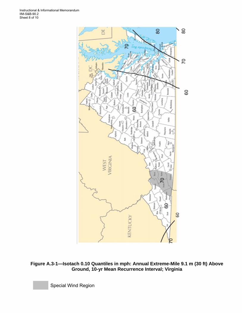
Appendix A (Wind maps developed based on charts from Appendix C AASHTO Standard Specifications for Structural Supports for Highway Signs, Luminaires, and Traffic Signals, 6th Edition, 2013)
Instructional & Informational Memorandum IIM-S&B-90.2 Sheet 8 of 10
Figure A.3-1—Isotach 0.10 Quantiles in mph: Annual Extreme-Mile 9.1 m (30 ft) Above
Ground, 10-yr Mean Recurrence Interval; Virginia Special Wind Region
60
70
80
60
70
80
70
60
70

Instructional & Informational Memorandum IIM-S&B-90.2 Sheet 9 of 10
Figure A.3-2—Isotach 0.04 Quantiles in mph: Annual Extreme-Mile 9.1 m (30 ft) Above
Ground, 25-yr Mean Recurrence Interval; Virginia
Special Wind Region
70
80
90
70
80
70
80
90

Instructional & Informational Memorandum IIM-S&B-90.2 Sheet 10 of 10
Figure A.3-3—Isotach 0.02 Quantiles in mph: Annual Extreme-Mile 9.1 m (30 ft) Above Ground, 50-yr Mean Recurrence Interval; Virginia
Special Wind Region
70
90
70
70
80
80
90
90
100
100