
spiral.imperial.ac.uk · Web viewTo understand the trade-off between additional turbocharger boost...
24
CHARACTERIZATION OF A SUPERCHARGER AS BOOSTING & TURBO- EXPANSION DEVICE IN SEQUENTIAL MULTI-STAGE SYSTEMS A. Romagnoli*, School of Mechanical and Aerospace Engineering, Nanyang Technological University,50 Nanyang Avenue, Singapore G. Vorraro, S. Rajoo, UTM Centre for Low Carbon Transport in cooperation with Imperial College , Malaysia C. Copeland, Mechanical Engineering Department, University of Bath, Bath, United Kingdom R. Martinez-Botas, Mechanical Engineering Department, Imperial College London, London, United Kingdom *Corresponding author: [email protected] Keywords: Supercharging, Engine downsizing, Multi-stage boosting, Heat transfer, Turbo-expansion, Positive displacement compressor ABSTRACT This paper proposes a detailed performance analysis and experimental characterization of a high-pressure supercharger in a multi-stage boosting system (turbo-super arrangement). Infact, besides the technical challenges associated with achieving adequate tuning, interoperability and driveability of multi-stage boosting systems, another challenge lies in their performance prediction during engine design. Indeed, performance maps of single boosting systems are usually provided by manufacturers and used as look-up tables in 1-D engine models. Tests are usually conducted in a standalone mode, with no information provided on the behaviour and performance of the combination of more than one boosting device. The supercharger was tested with varying inlet pressures and temperatures matching on-engine operating conditions and the results were then used to assess the effectiveness of 1-D engine models performance prediction when dealing with multi-stage boosting systems. An assessment on heat transfer in superchargers was also carried out together with the analysis on the nature of non-dimensional performance maps when dealing with a pressurized inlet. Finally, the analysis also looked into the opportunity to use the superchargers as expanders (‘expansion mode’) in order to cool the air charge entering the engine. The results showed that there is discrepancy between the efficiency values computed by 1-D engine models and those obtained experimentally under pressurized/heated inlet air conditions; the correction of the efficiency maps for heat transfer plays a significant role in the final measured efficiency and the correction of the maps for varying inlet temperatures must be carried out in order to avoid incurring in apparent efficiencies greater than unity. The experiments on the supercharger in ‘expansion mode’ showed that low isentropic efficiencies can be achieved; despite this, 1-D engine simulations showed that it is possible to achieve savings of a few percentage points in Brake Specific Fuel Consumption when the supercharger is used to recover some throttling energy by expanding the close- to-ambient pressure to the required intake pressure. 1 INTRODUCTION In the recent years the automotive sector has been pushed to heavily downsize engine capacity to meet CO2 emissions regulations; therefore, in order not to compromise on engine performance, multi-stage boosting systems arrangement, in which two or more charging devices are used to provide greater system capability are being explored [1–2]. In Table 1 is given an overview of some of the most common multi-stage boosting systems arrangement. In a Parallel Multi-Stage arrangement, each compressor delivers half of the total air flow but the full boost pressure; this allows two smaller turbochargers to meet the torque requirements over a wider range compared to a single, larger turbocharger. In the Series Multi-Stage arrangement, the boost developed from the low pressure (LP) stage is fed into the high pressure (HP) stage so that the final boost is multiplied. In the Super-Turbo and Turbo-Super arrangements a turbocharger is paired with a supercharger [3, 4, 5]. The advantage of a mechanically driven supercharger is that there is no hesitation in response during a load step; the engine drives the supercharger with a fixed ratio, meaning no turbo lag effect is present.
Transcript of spiral.imperial.ac.uk · Web viewTo understand the trade-off between additional turbocharger boost...

CHARACTERIZATION OF A SUPERCHARGER AS BOOSTING amp TURBO-EXPANSION DEVICE IN SEQUENTIAL MULTI-STAGE SYSTEMS
A Romagnoli School of Mechanical and Aerospace Engineering Nanyang Technological University50 Nanyang Avenue Singapore
G Vorraro S Rajoo UTM Centre for Low Carbon Transport in cooperation with Imperial College Malaysia
C Copeland Mechanical Engineering Department University of Bath Bath United KingdomR Martinez-Botas Mechanical Engineering Department Imperial College London London United
KingdomCorresponding author aromagnolintuedusg
Keywords Supercharging Engine downsizing Multi-stage boosting Heat transfer Turbo-expansion Positive displacement compressor
ABSTRACT This paper proposes a detailed performance analysis and experimental characterization of a high-
pressure supercharger in a multi-stage boosting system (turbo-super arrangement) Infact besides the technical challenges associated with achieving adequate tuning interoperability and driveability of multi-stage boosting systems another challenge lies in their performance prediction during engine design Indeed performance maps of single boosting systems are usually provided by manufacturers and used as look-up tables in 1-D engine models Tests are usually conducted in a standalone mode with no information provided on the behaviour and performance of the combination of more than one boosting device
The supercharger was tested with varying inlet pressures and temperatures matching on-engine operating conditions and the results were then used to assess the effectiveness of 1-D engine models performance prediction when dealing with multi-stage boosting systems An assessment on heat transfer in superchargers was also carried out together with the analysis on the nature of non-dimensional performance maps when dealing with a pressurized inlet Finally the analysis also looked into the opportunity to use the superchargers as expanders (lsquoexpansion modersquo) in order to cool the air charge entering the engine
The results showed that there is discrepancy between the efficiency values computed by 1-D engine models and those obtained experimentally under pressurizedheated inlet air conditions the correction of the efficiency maps for heat transfer plays a significant role in the final measured efficiency and the correction of the maps for varying inlet temperatures must be carried out in order to avoid incurring in apparent efficiencies greater than unity The experiments on the supercharger in lsquoexpansion modersquo showed that low isentropic efficiencies can be achieved despite this 1-D engine simulations showed that it is possible to achieve savings of a few percentage points in Brake Specific Fuel Consumption when the supercharger is used to recover some throttling energy by expanding the close-to-ambient pressure to the required intake pressure
1 INTRODUCTION In the recent years the automotive sector has been pushed to heavily downsize engine capacity to
meet CO2 emissions regulations therefore in order not to compromise on engine performance multi-stage boosting systems arrangement in which two or more charging devices are used to provide greater system capability are being explored [1ndash2] In Table 1 is given an overview of some of the most common multi-stage boosting systems arrangement In a Parallel Multi-Stage arrangement each compressor delivers half of the total air flow but the full boost pressure this allows two smaller turbochargers to meet the torque requirements over a wider range compared to a single larger turbocharger In the Series Multi-Stage arrangement the boost developed from the low pressure (LP) stage is fed into the high pressure (HP) stage so that the final boost is multiplied In the Super-Turbo and Turbo-Super arrangements a turbocharger is paired with a supercharger [3 4 5] The advantage of a mechanically driven supercharger is that there is no hesitation in response during a load step the engine drives the supercharger with a fixed ratio meaning no turbo lag effect is present Mechanically supercharging an engine is a well-established practice in aero-engines [67] but it is fairly recent practice in the automotive sector Depending on the way the gas is being compressed two main types of superchargers can be identified centrifugal and positive-displacement compressors [8] Centrifugal compressors are smaller lighter and more efficient than positive-displacement compressors The main drawback for centrifugal compressors is that they can provide low boost at low engine speed since the boost supplied increases with the square of the rotational speed [9] In addition to this to increase the boost pressure high tip speeds are required in order to avoid this centrifugal compressors need a step-up gear box which might lead to additional mechanical losses [10] Recently two promising compressors namely V-Charge and SuperGen have demonstrated to
succeed in achieving continuous variation in the drive ratio thus showing a significant performance potential as HP stage in a multi-stage boosting system [1011]
Positive displacement compressors have the advantage to offer a constant boost characteristic since the amount of air pumped is proportional to the engine speed and supercharger size Unlike centrifugal compressors which require a step-up gear box positive-displacement compressors can be integrated more easily since it requires a simple drive system to the engine crankshaft [9] The most frequently used positive-displacement compressors are the twin-screw type and the Roots type [1213] Both Volkswagen and Volvo used Eaton (Roots-type) superchargers in their production multi-stage boosting engines [141516] and Lotus Audi and Jaguar have used them as single stage boosting devices [171819]
Table 1 Overview and comparison of some multi-stage boosting systems arrangements [202138]Parallel Multi-Stage arrangement
+ Higher Boost than single stage+ Good altitude performance- Limited transient response compared to
single stage- Complex installation - Associated cost increase- Associated packaging space increase- Higher thermal inertia
Series Multi-Stage arrangement
+ Higher Boost than PMS+ Good altitude performance+ Good transient response- Complex installation - Associated cost increase- Associated packaging space increase- Higher thermal inertia
Super-Turbo arrangement (LP supercharger)
Turbo-Super arrangement (HP supercharger)
+ Comparable to Series Multi-Stage arrangement in terms of boost levels+ Best transient response (due to supercharger in place of turbine)+ Slight efficiency penalty compared to Series Multi-Stage arrangement- Complex installation - Associated cost increase- Associated packaging space increase- Higher thermal inertia
The UltraBoost project aims to demonstrate that it is possible to downsize a large naturally aspirated gasoline engine by 60 while still maintaining same torque and driveability attributes An additional aim of the project is that of showing that with such a large level of engine downsizing it is possible to provide a major proportion of a route towards a 35 reduction in vehicle tailpipe CO 2 on the New European Drive Cycle [22]
The baseline engine platform used is a Jaguar Land Rover (JLR) naturally-aspirated 50 litre V8 engine to be downsized to a 20L displacement across four cylinders [36] In order to achieve the aforementioned targets a number of studies and modifications had to be carried out to the engine (eg knocking injection systems valvetrains etc) and the air management system which has to
HP stage
HP stage
LP stage
deliver a charging pressure of up to 35 bar absolute to meet the target Brake Mean Effective Pressure of 35 bar in Fig 1 a comparison between the baseline and the UltraBoost engine power and torque is given After a selection process assessing several boosting configurations a turbo-supercharger arrangement (ie turbo-super) was chosen [23] as shown in Table 1 in particular a Garrett GT30 turbocharger was selected as the Low Pressure (LP) stage while an Eaton supercharger is the High Pressure (HP) side of the boosting system The Eaton is a Roots type Twin Vortices Series with a clutched single speed drive that is able to run with reasonably high adiabatic efficiency over a wide range of operating conditions
However the aim of this work is to provide an insight into the performance and thermal characterization of a high-pressure supercharger in a sequential multi-stage boosting system arrangement In more detail the following aspects will be investigated
- Impact of different inlet pressures and temperatures on 1-D engine models supercharger performance prediction Through the years 1-D engine models have extensively been used by engine makers since these provide fast yet reliable results which can be used during the engine design phase The theory behind these models is well established and it relies on extensive database which comes from many years of experimental activities and models improvement Inside these models turbochargers and superchargers represent the boundary conditions for the engine inletoutlet since they determine the inlet pressure and temperature of the chargedischarge air feedingleaving the engine Even though turbocharger models are well established turbochargersrsquo turbines and compressors present longstanding issues related with performance maps and unstable operating conditions In particular turbine maps are narrow in range and force engine simulation software to rely significantly on maps extrapolation [24 25] On the other hand unstable behaviour of compressors [26] leads to strong inletoutlet pressure oscillations and mass flow rate inversion phenomena that should be implemented inside the numerical models In addition to this by installing sequentially arranged LP and HP compressors the secondary compression stage (HP) operates at different inlet pressures and temperatures than those under which they have been tested and designed for Recently several authors analysed multi-stage boosting systems from a numerical point of view by means of 1-D models both for gasoline and diesel engines [2728] More in detail these papers carry out assessment of the engine performance using different layout and configurations like super-turbo and turbo-super with some simplified assumptions about the supercharger and turbocharger performance maps Furthermore no details or considerations have been done by the authors on the impact of different inlet conditions at the second stage of the boosting system running indeed the 1-D models with the performance maps obtained by the manufacturer in standard conditionsRelying on existing works [2728] the experimental evaluation of the supercharger performance operated at different than ambient inlet conditions represents the starting point for the current paper Furthermore with the aims to understand how well the HP performance and output parameters are predicted by current 1-D engine software a 1-D model of the multi-stage boosting system and engine has been done Coupled to this the proposed study also aims to look into the effects of heat transfer on supercharger performance
- Heat transfer effects on supercharger performance Extensive research over the last few years on heat transfer in turbochargers [29] resulted in a significant understanding of their thermal behaviour in this way optimization of design procedures has been improved together with the development of simulation tools The aim of this analysis is that of providing an additional contribution on the understanding of the heat transfer process occurring within a supercharger previous works assessed the impact of the thermal energy produced by the mechanical losses on the mechanical components of the machine focusing on the clearances variation due to the thermal distortion of the rotors and the casing [30] Other authors carried out similar analysis on a single screw compressor by means of Finite Element Analysis and experimental data of the thermal field collected using a thermographic camera aimed on the external side of the supercharger housing [31] Finally further studies on heat transfer was made by means of CFD or theoretical models such as Fuzzy Wavelet [3233] Despite of the aforementioned works the analysis proposed in this paper relies on the experimental results gathered for the supercharger tested under different inlet temperatures with the aim to assess the impact of the heat transfer on the machine performance
- Assessment of supercharger performance operated as an expander as part of a turbo-expansion arrangement One of the most common practices to enhance the specific power output of an internal combustion engine is to pressurize the air charge using a supercharger andor turbocharger on the intake line in order to increase air density and therefore volumetric efficiency of the machine During the compression process a temperature rise will naturally take place and this is not a desired effect because it reduces air density and lowers the knock limit of the engine Thus it makes intercooling necessary to reject thermal energy to the environment and lower the inlet temperature of the fluid However even if a large intercooler is adopted it is not possible to lower the temperature to ambient conditions because every heat exchanger has efficiency below unity For
this aim a turbo-expansion system could be used on the engine This concept is not new and it has been widely used on commercial aircrafts and other applications (eg air conditioning systems) The idea is very simple if a surplus of pressure energy is available inside the air charge it can be expanded using a turbine (expander) recovering mechanical energy and at the same time lowering the temperature of the fluid furthermore if an intercooler is used it is possible to lower the temperature of the air charge below ambient By considering a supercharger besides serving as a compressor (lsquocompression modersquo) this could be used as an expander (lsquoexpansion modersquo) thus significantly extending the operating range of a turbo-super configuration To be more specific the supercharger supplies additional boost at low engine speedhigh load when the exhausts energy is not sufficient to drive the turbocharger (lsquocompression modersquo) at high engine speedhigh load instead when the exhausts energy is sufficient to drive the turbocharger the supercharger could switch into lsquoexpansion modersquo and be operated as an expander In the field of Organic Rankine Cycle many studies has been conducted on screw compressors used as expander More in particular CFD analysis [34] and numericalexperimental comparison [35] has been carried out on screw compressor more suitable for industrial applications Relying on what previously said about the opportunities to operate a supercharger as an expander there is a strongly increasing interest by the supercharger and engine manufacturers to use that methodology on internal combustion engine as demonstrated by Eaton [36] Finally the aim of this analysis is that of providing an experimental analysis on the supercharger performance when run in lsquoexpansion modersquo and compare it with other similar concepts already been proposed [37]
2 EXPERIMENTAL ANALYSISIn this section a description of the test setup and the results obtained for the supercharger under
study is given The test set-up can be divided into three main parts consisting of a driving assembly an inlet and exit to the supercharger assembly (refer to Fig 2A) Torque required at various supercharger operating points was measured with a torque meter placed after the crankshaft pulley (Figs 2B amp 3) The main thermodynamic parameters (pressuretemperature) were measured at the inlet and the exit of the supercharger (Figs 2C amp 2D) except for the mass flow rate which was only measured at the inlet to the supercharger by means of a V-cone (DP meter from ABLE plusmn05 RDG Accuracy plusmn01 or better Repeatability) Pressures and temperatures were measured using static pressure tappings (from Scanivalve) and K-type thermocouples respectively It is worth noting that in order to replicate the actual configuration of the engine the pulleysbelt assembly on the supercharger side has the same layout and the same components as the real engine (green box in Fig 3)
Figure 1 UltraBoost Target and Experimental Power amp Torque UltraBoost Torque is limited at low engine rpm due to lower than expected supercharger performance
Figure 2 A- Supercharger test rig overview B- Driving assembly C- Inlet supercharger D- Exit supercharger
B
C
D
Figure 3 Supercharger testing options
The inlet to the supercharger is made by modular units allowing for different types of tests Referring to the black boxes in Fig 3 three options were considered during testing
Option 1 consists of exposing the supercharger to ambient pressure and temperature this option was tested in order to calibrate and validate the test set-up against the performance maps provided by the supercharger manufacturer
Option 2 consists of pressurizing and heating the inlet air to the supercharger By doing so it is possible to replicate the same flow conditions as those experienced by the supercharger when in a turbo-super configuration (ie operating in compression mode as HP stage) With
A
this set of test data the assessment on 1-D engine simulation and heat transfer effects could be carried out (refer to Section 3)
Option 3 consists of having pressurized inlet but no heater with this arrangement the supercharger is run in lsquoexpansion modersquo and the results obtained could be used to assess the potential of turbo-expansion concept (refer to Section 4)
It is worth noting that in Options 1 amp 2 the supercharger is driven by the electric motor the rotational speed is kept constant and the pressure ratio between the inlet and exit of the supercharger is varied by means of the inletexit valves However in Option 3 the supercharger is driven by the pressurized inlet air the belt from the electric motor is disconnected from the torque meter which is instead loaded by applying an external brake load (refer to Fig 3)
The performance parameters from the supercharger testing were calculated using Eq 1 to 5 Based on the measurements of the mass flow rate pressure temperature torque and rotational speed the total-to-total efficiency (ηTT) and the Power Ratio (PR) could be calculated The Power Ratio is defined as the ratio between the power consumed by the supercharger (W SC Eq 4) and the mechanical power (WSHAFT Eq 3) from the electric motor This parameter intends to represent a pseudo-mechanical efficiency for the SP-EB-CP assembly (Fig 3 ndash green box) since this replicates the same layout as that of the UltraBoost engine
T T iquestT S +C2
2∙ c p(1 ) PT iquest PS+05 ∙ ρ ∙C2(2)
W SHAFT=τ SHAFT ∙ NSHAFT (3 )W SC=mINL ∙ c p (T T OUTminusT T INL ) (4)
ηTT=(PRTT )γminus1 γminus1
(T T OUT TT INL )minus1where PRTT=
PT OUT
PT INL(5)
Powerratio=W SC
W SHAFT(6 )
21 Baseline supercharger testing Figures 4-5 show the comparison between the performance results obtained at Imperial College
London (Option 1 in Fig 3) and those provided by the supercharger manufacturer Figure 4 shows that the mass flow rate curves are consistent with the original maps from Eaton and that there is good agreement between the different set of data for rotational speeds between 2000 rpm and 16000 rpm For larger rotational speeds (18000 rpm rarr 20000 rpm) the discrepancy with Eaton superchargerrsquos maps becomes more significant This could for instance be attributed to additional leakage that could not be assessed with current instrumentation however the deviations were found to fall below 4 and this was accepted and decisions made to proceed with further analysis As per the supercharger efficiency Fig 5 shows that there is also agreement with the supercharger manufacturersrsquo performance maps the Power Ratio values have been reported in the same figure (secondary axis) using dashed lines For higher rotational speeds the power ratio is as high as 85 and it only falls below 75 for rotational speeds between 2000 rpm and 6000 rpm this speed range is not of interest since with gear ratio of 588 between the engine crankshaft and the supercharger the engine speed is less than 1000 rpm which corresponds to idling conditions where no boosting is required
Figure 4 Validation for supercharger mass flow rate measurements
Figure 5 Validation for supercharger efficiency measurements (primary axis) and plot of the Power ratio (secondary axis)
22 Supercharger testing with pressurized and heated inlet airIn order to replicate the same flow conditions as those encountered on real engine conditions these tests investigated the performance of the supercharger with six different pressures and temperatures
(see Table 2) In order to avoid excessive thermal and mechanical stress on the test rig the tests were carried out for a single rotational speed of 8000rpm
Table 2 Supercharger pressures and temperatures inlet conditionsSC Speed [rpm] T1 [K] P1 [kPa]
8000 ambient 1508000 ambient 1808000 320 1508000 320 1808000 350 1508000 350 180
Figure 6-A amp 6-B show the supercharger corrected and non-corrected mass flow rates under the inlet conditions of Table 2 as expected different operating conditions occurs at the same rotational speed1
Figure 6 A-Measured mass flow rate and B-Corrected mass flow rate
As for the efficiency this was calculated using the adiabatic isentropic efficiency equation (Eq 5) It can be seen in Fig 7 that the efficiency is not affected by different inlet pressure (black red and blue dashed line) and it leads to values similar to those of the baseline (ie ambient inlet temperature and pressure) Conversely the plots show that temperatures higher than ambient give efficiencies trends much different than the baseline In particular values diverge the most for high inlet temperatures and low pressure ratios under these conditions the efficiency reaches values greater than unity this might be attributed to heat transfer effects
1 The mass flow rate has been corrected with the following equation (Eq 7) adopting 28815K and 101325Pa as reference temperature
and pressure (Tref and pref) respectively
miquest=mradic T 1
T ref
p1
pref ( 7 )
A B
Figure 7 Supercharger efficiency
By considering Fig 8-9 it can be shown that the efficiency definition is based on temperature measurements which in turn can be affected by heat transfer phenomena The layout proposed in Fig 8 is a schematic of the test setup under Option 2 (ie pressurized and heated inlet) The temperature sensors are indicated as Tamb T1a T1b T2a T2b the heat transferred to the inlet air is indicated as QH whereas the heat transferred to the environment is indicated as Qrsquoout QSC amp Qrsquorsquoout for the inlet pipe supercharger casing and exit pipe respectively The efficiency can be calculated using the four possible combinations available with the reading given by T1a T1b T2a T2b The more realistic efficiency values can be obtained by using T1a and T2a that are located closer to the inlet and outlet port respectively The efficiency values for each combination will differ from one another and could be larger than unity since heat transfer can occur along the pipe between the measurement points and the supercharger casing For instance this might occur if the inlet pipe is not completely insulated and T1b and T2a are used for the efficiency calculation (refer to Fig 9) Indeed due to the heat transfer (Qrsquoout) the actual inlet temperature is T1a and consequently considering an actual adiabatic process the temperature at the end of the compression will be T2a much different from the T2ex expected (see Fig9) However since the measured temperature corresponds to location T1b the efficiency is computed on an apparent compression process instead of the actual process represented by the orange dashed line and the green continuous line in Fig 9 If we consider Eq 8 to calculate the supercharger efficiency by substituting TTINL with T1b TTOUT with T2a and TTOUTis with T2is some efficiency values could turn out to be larger than unity
ηTT=T T OUTisminusT T INL
T T OUTminusTT INLwhereT T OUTis=T T INL ( PRTT )γminus1 γ(8)
For the considered compression process shown in Fig 9 relying on the earlier explanation the less accurate efficiency calculations are obtained using T1b and T2b temperatures (red dashed line in Fig 9) However the heat transfer along the inlet and outlet pipe is not the only heat transfer process that affects efficiency computation the heat transferred from the fluid to the supercharger rotors and casing can also lead to misleading results
Previous studies carried out by Stosic et al [39] assessed the heat transfer process for a compressor with rotor diameter of 102mm rotating at 10000rpm a pressure ratio of 6 and power input of 47kW In their work it was assumed that the temperature field of the rotor could be considered linear along the rotation axis with the highest temperature near the discharge port where the fluid pressure is maximum The temperature reached a peak of ~530K with a standard rotor and ~380K with a water cooled rotor The latter showed that the thermal power transferred from fluid to the rotors was ~100W showing that the amount of heat transferred could in general be neglected if compared to the input power This is not the case for the results presented in the current paper since
Stosic et al [39] assessed the thermal power transferred to the rotors on a compressor working with ambient inlet temperature and consequently with minimum heat transfer Furthermore no remarks were made on the efficiency or the heat transferred to the environment
The casing of the supercharger tested in this paper was not insulated With inlet charge air temperatures higher than ambient not only the discharge zone is influenced by high
temperatures but the whole casing as well Thus the heat transferred from fluid to the casing and discharged into to the environment (convection thermal exchange) can be much higher than that assessed by Stosic et al [39]
T1b= TTINL =location at which the temperature was measured during testsT2b = TTOUT = location at which the temperature was measured during tests (= T2a since the exit duct was insulated)
Figure 8 Schematic of Option 2 layout
Figure 9 T-s diagram for the compression phase
Figure 10 Thermal power loss vs pressure ratio
One way to estimate the impact of heat transfer on the supercharger performance could be that of assuming that
1 The thermal power loss to the environment occurs through the inlet pipe (which was partially
insulated) and the supercharger casing (which was no insulated) the exit pipe was insulated and no heat transferred is considered to occur
2 For a given rotational speed the supercharger efficiency is the same as the baseline (ie it is assumed that the heat loss is the same as the baseline testing refer to Section 21) this means that the inlet air temperature to the supercharger only affects the exit temperature
Based on these two assumptions by reversing Eq8 it is then possible to compute a corrected inlet temperature (Eq 9) and therefore the thermal power loss (Eq 10) through the inlet duct and the supercharger casing
T 1 corr=T T OUT ∙ ηTT corr
(PRTT )γminusηTT corrminus1( 9 )W HT=mINL ∙ cp (T 1aminusT T INL )(10)
where T1corr is the corrected inlet temperature TTINL and TTOUT are the measured inlet and outlet temperatures respectively and ηTTcorr is the efficiency extrapolated by the baseline efficiency curves
Figure 10 shows the results of the thermal power loss as expected the results of the test at 350K and 150kPa represent the worst case in terms of heat loss with peak value of ~1kW
Figure 11 A- Power Ratio and B- Corrected Power Ratio
The corrected inlet temperature could be used also in Eq4 in order to correct the Power Ratio for heat transfer Fig 11-A shows that by using uncorrected data the trend of the Power Ratio is temperature dependent however since the power ratio is supposed to be a measure of mechanical efficiency (ie mechanical transmission) this parameter should be temperature independent Hence by recalculating the power consumed by the supercharger the Corrected Power Ratio curves are given in Fig 11-B it can be seen that in this way the power ratio seems to be less dependent to varying inlet temperatures
3 SEQUENTIAL MULTI-STAGE BOOSTING SYSTEMS 1-D MODEL FOR HP STAGEThe intent of this section is to compare supercharger experimental performance to data collected
from a 1-D engine model of the UltraBoost engine containing supplier maps Although the model has been validated at full and part load against engine dynamometer data [2212232930] the intent here is mainly to compare the supercharger manufacturerrsquos performance data against the data collected by Imperial College
First it is helpful to introduce the 1D model used in this comparison This model was developed using commercial software GT-Power that offers detailed internal combustion engine modelling along with the air and exhaust manifolds ductwork and boost system components This software can be classed as a lsquowave-actionrsquo code in that it is a one-dimensional simplification of unsteady compressible flow within a network of pipes and junctions This simplification of the Navier-Stokes equations is generally considered acceptable where the length to diameter ratio results in a full developed turbulent flow While it is not appropriate to provide the full list of governing equations and closure models due to the desire for brevity the reader is encouraged to refer to reference [40]
Figure 12 provides a block diagram of the GT-Power model that shows the 1D pipe connections four cylindercombustion junctions and numerous connections modelling the intake and exhaust flow paths Labels in this figure show the low pressure (LP) turbocharger compressor and turbine The HP compressor as labelled corresponds to the Eaton supercharger and features two charge-air coolers upstream and downstream of it A low pressure EGR system is also evident All the compressor and turbine behaviours are modelled using characteristic performance maps that are obtained from the component suppliers The use of such lsquolook-up tablesrsquo for component modelling is one of the issues explored here since is assumed that the conditions under which the components are tested in the industrial gas-stands are easily transferred to the lsquorealrsquo on-engine behaviour by the use of non-dimensional or pseudo-non-dimensional parameters
A B
Figure 12 Block diagram of GT-Power 1D model of the Ultraboost Engine and Airpath
The engine specifications are given in Table 3
Table 3 Engine specifications Engine Type - Inline-4-cylinderCapacity cc 1991Compression ratio - 901Firing Order - 1-3-4-2Combustion System - Gasoline GDISpec Power kWl min 142 6500Spec Torque Nml min 255 3500Max BMEP bar min 35 3500 and 25 1000 amp6500Air Charging System - HP Eaton R410 LP Honeywell GT30
The process of comparison was as follows The 1D model was used to identify four full load test points where the bypass valve is closed These operating points were then replicated by using Option 2 for the test set-up to achieve the same supercharger rotational speed mass flow inlet pressure and inlet temperature In order to avoid the premature damage of the supercharger due to large inlet temperatures and pressures during the tests the supercharger rotational speed of 15000 rpm (ie 2500 engine rpm) was not exceeded even though the engine control strategy maintains the supercharger engagement up to 3500 engine rpm - corresponding to 21000 supercharger rpm2 Table 4 provides the comparison between the 1-D simulation results and the tests for different supercharger inlet conditions and rotational speeds As it can be seen in the table the comparison between the data from the tests and the 1-D simulations differ no more than 1
Table 4 Supercharger inlet conditions (1-D simulationImperial Tests)NEngine [rpm] 12501251 15001504 20001998 25002507
2 Unlike real engine operating conditions for which the supercharger is only exposed to high pressures and temperatures for few seconds the supercharger steady state testing required a settling time for all the thermodynamic parameters of several minutes
NSC [rpm] 73507359 88208844 1176011750 1470014742Mass flow [kgs] 00600057 00939009 01800172 02650254Inlet Pres [bar] 14291434 1734173 23202321 2832278Inlet Temp [K] 303302 320320 333332 347353
The comparison between measured and simulated results of supercharger outlet pressure and temperature power and efficiency is shown in Fig 13 This demonstrates the difference in the data that GT-Power has extracted from the manufacturersquos supercharger maps and the measured data from the Imperial College test facility
It is apparent that the trend of the 1-D simulation is very similar to the experimental data even though some discrepancies do appear at higher engine rpm Here the discrepancy between the measured and computed outlet pressure has a variation of about 6 with 021 bar of difference In particular the power consumption of the supercharger shows larger variations with increasing the engine speed eg at 2500 engine rpm there is a variation of about 307 with a difference ΔPower of 353kW
In order to explain these discrepancies one needs to consider how the output power and efficiency is derived using the Imperial College facility (refer to equations 4 and 5) These calculations rely on the gas temperatures before and after compression Referring to the supercharger outlet temperature (Figure 13) at 2000rpm and 2500rpm it is clear that the Imperial college outlet temperatures are below that of the 1D simulation for the same operating conditions This demonstrates that the heat transfer state in the manufactures maps is different to that in the Imperial College experiments It is clear from the equation of efficiency that where the outlet temperature is influenced by both heat transfer and work transfer the thermodynamic measurements of power and efficiency are affected This is borne out by the differences in supercharger efficiency plotted in Figure 13 Note that similar discrepancies have been investigated in by the authors in centrifugal compressors [32 26] It is also undoubtedly true that a stronger heat flux through the casing can be expected with raised inlet temperatures and explains the difference between the imperial college data and the manufactures data (in the 1D model) where the latter is likely tested under ambient inlet conditions
Figure 13 Comparison between measured and predicted SC data
The outcomes of this work demonstrate the importance in first the approach to measuring the supercharger efficiency and second the importance of separating heat transfer from work transfer where a thermodynamic performance calculation is made There are two consequences of a failure to take this into account
Figure 14 Turbo expansion process A - Standard [4344] B- Whelans [4546] C- Turbo-super arrangement
1 The prediction of outlet temperature will be incorrect This can impact the design decisions of the charge air cooler and the prediction of manifold charge temperature (and thus by extension engine performance)2 An incorrect evaluation of isentropic efficiency This is fundamental for the engine simulation since the supercharger parasitic load will be incorrectly modelled
The clear recommendation of this work is that heat transfer must be considered in any 1D model were a supercharger is present Positive displacement compressors may be more susceptible to this due to the larger wetted area ndash although this is unconfirmed and must be the subject of further work There are two possible methods to improve the modelling discrepancy due to heat transfer Where the efficiencypower is assessed thermodynamically the first method is to insulate the compressor and ductwork heavily to simulate an adiabatic compressor during experimentation The second approach where this is not possible is to developed a heat transfer model to lsquoback-calculatersquo the adiabatic performance There are numerous examples of such models applied to centrifugal compressors
4 SUPERCHARGERS AS AN EXPANDER41 Turbo-expansion initial simulation study
The concept of charge air-cooling by turbo-expansion applied to internal combustion engines was developed in the 1950s and 60s [41 42] It was successfully applied to natural gas fuelled power generation engines enabling useful power increases and providing protection from the detonation effects of varying fuel properties Perhaps one of the most notably attempts to apply this concept is represented by the NOMAD project by Lotus Engineering [43 44] Using an Opcon mechanical twin-screw expander this project sought to demonstrate the advantages of this technique as shown in Fig 14-A This concept can be applied to any turbocharged engine equipped with both a compressor and a turbine-like expander on the intake The turbocharging system is designed to achieve maximum utilization of the exhaust energy from which the intake charge is over-boosted After the intercooler the turbine-like expander expands the over-compressed intake charge to the required plenum pressure and reduces its temperature whilst recovering some energy through the connection to the crankshaft Since the expander is situated after the intercooler the charge air can potentially be expanded to sub-ambient temperatures depending on the effectiveness of the heat exchanger and expansion ratio Thus it is anticipated that such a concept has benefits for knock resistance and energy recovery However note that depending on the temperature drop this can require the turbocharger to provide additional boost pressure such that the charge pressure is greater than the required engine boost pressure This requirement for additional boost can increases engine backpressure and potentially pumping work
Another approach proposed by Whelans et al [4546] consists of a slightly different turbo-expansion arrangement where the intake pressure is raised and lowered by a compressor and a turbine respectively that are placed in the intake flow path (refer to Fig14-B) Sub-ambient air charge temperature is reached by removing thermal energy in a second charge air cooler between compressor and turbine stages The turbo expansion unit is energy balanced by specifying a larger turbine expansion ratio than compression ratio
In this paper it is proposed another approach to the earlier mentioned turbo-expansion concepts In the proposed turbo-super configuration the Eaton supercharger is serving the dual function of providing boost at low engine speed while behaving like a turbine presenting an indirect means to recover exhaust gas energy at high engine speed (refer to Fig 14-C) Obviously the Eaton supercharger was not designed to be used as an expander and to the authorsrsquo knowledge there are no available performance data of this type of machine operated in that way For this reason the Imperial College experimental facility was used to assess the performance of the Eaton supercharger
A
B
C
in an expansion mode While this dual purpose is not possible with a fixed ratio drive such a switch between compressor and expander operation could be envisaged using such a variable ratio drive system42 Experimental characterization of Eaton Supercharger as expander
In order to measure the performance of the supercharger in expansion mode the supercharger test facility was configured as shown in Option 3 (refer to Figure 3) All of the thermodynamic and mechanical parameters were measured and the results are presented in Fig 15-17 Fig15 shows the supercharger mass flow rate curves for three different constant speeds (from 4000 rpm to 8000 rpm) when operating in expansion mode in the same figure are also reported the equivalent supercharger mass flow curves for the same speeds Figure 16 compares the total-to-total isentropic efficiencies between both the operating modes of the supercharger The expansion efficiency was calculated using the thermodynamic relation for a turbine expansion as shown in Eq 11 It is apparent from the figure that there is a drop in efficiency when the supercharger is used as an expander these results are consistent with those reported by Turner et al [26]
ηTT=1minusiquestiquest
Figure 17 shows the power that can be generated and thus potentially be returned to the engine if it is operated as an expander These results represent a potentially new use of an Eaton supercharger even though it is also clear that in lsquoexpansion modersquo the supercharger can only deliver isentropic efficiencies between 40-50 It is this rather poor expansion efficiency that may lead to diminishing returns from a sub-ambient intake air charge To understand the trade-off between additional turbocharger boost (turbine backpressure) and the benefits from turbo-expansion across a supercharger further modelling work has been carried out using the data presented here
Figure 15 Pressure and Expansion Ratio of Eaton Supercharger versus Mass Flow
Figure 16 Total to total isentropic efficiency of the supercharger operating as a compressor and expander
Figure 17 Power harvested from the supercharger operating as an expander
43 Potential of the supercharger as an expansion device Since the turbo-super arrangement places the supercharger downstream of the turbocharger the
1-D simulation aims to answer one specific question namely can a twin-vortices supercharger be used as an effective expander While this would require additional boost from the turbocharger there are operating points where there is excess turbine energy that could be used to generate additional boost by modulating the wastegate In this situation a mechanically connected expander could present an indirect means to recover exhaust gas energy the engine arrangement is the same as that in Figure 14-C
The first option being assessed is mainly proposed to address the issue of high inlet temperature under full load whilst recovering some energy that otherwise would be wasted on the exhaust To be
more specific the research model was equipped with a centrifugal turbocharger and a Continuous Variable Transmission (CVT) driven positive displacement supercharger The CVT driven supercharger at the high-pressure (HP) stage could be functioned as a normal compressor at high load and low speed while behaving like an expander under high load and high speed Unlike the conventional compression mode of the supercharger the lsquoexpansion modersquo utilized the turbocharger to over-boost the intake charge by further closing the wastegate while the supercharger by the speed control acts like a turbine expanding the over-compressed intake charge to the required plenum pressure and reducing its temperature It is anticipated that such a concept is beneficial for knock resistance due to the intake temperature reduction From the point of view of energy recovery it also provides an innovative approach which indirectly reclaims some of the otherwise wasted exhaust energy The simulation results showed that the expansion-cooling task is accomplished but with the poor isentropic efficiency of the expander and poor breathing characteristics hence an improvement in BSFC could not be found However if the isentropic efficiency could be increased from 45 to 72 a net BSFC improvement of 1 could be achieved
Another option which was investigated is that of using the CVT driven supercharger to replace the conventional throttle for SI engines at part load to recover some throttling energy by expanding the close-to-ambient pressure (1bar) to the required intake pressure (normally lt05bar) It is conceived that by reclaiming some throttling loss through the supercharger part load fuel efficiency could be improved In addition the cooling effect of the supercharger expansion could lighten the load of the after-cooler which is beneficial for knock resistance and volumetric efficiency for the following possible high load cycle By recovering some throttling loss through the supercharger part load fuel efficiency could be improved by up to 3 depending on the operating points However the issues of limited supercharger operating range with an existing production CVT condensation fuel evaporation and additional pumping work would need to be addressed before taking the supercharger-throttling gas exchange process from concept to reality The rotational speed of the supercharger could also be used as a control mechanism to attain the required part load target This is subject to ongoing studies
5 CONCLUSIONSThe current article describes the outcomes of experimental and numerical research on a
supercharger for a multi-stage boosting system formed by an Eaton Twin Vortices Series supercharger and a GT30 turbocharger The Eaton is a Roots type supercharger able to provide adequate mass flow rates and pressure ratios for engine application with high adiabatic efficiencies all over the operating range The aim of this work is the experimental assessment of the performance of the supercharger under different operating conditions such as different inlet pressure and temperature Furthermore thorough investigations were carried out in a dedicated test facility at Imperial College London on the heat transfer effects and on performance of the supercharger operated as an expander
Firstly a baseline testing was carried out with supercharger operating in ambient inlet conditions using the test Option 1 test set-up Performance maps were obtained in the rotational speeds range of 2000-20000rpm The experimental test data collected are consistent with the maps provided by Eaton with a good agreement in the speed range from 2000 to 16000 rpm
The supercharger was then characterized for one rotational speed (8000 rpm) in above ambient conditions (inlet temperatures of 320K and 350K pressures of 150kPa and 180kPa The test results showed that varying inlet pressure does not affect the supercharger efficiency on the contrary varying inlet temperatures strongly influence the supercharger efficiency (leading to values bigger than unity) if heat transfer effects are not duly accounted for Assessment of the heat transfer was carried out assuming that at the same pressure ratio the efficiency of the supercharger does not change even with high inlet temperature However the isentropic efficiency calculation no longer holds with inlet heat air and therefore should be corrected The thermal power loss through the supercharger was calculated and it can achieve up to 1kW
The supercharger was also tested with similar speed inlet pressure and temperature as those predicted by the engine model at the inlet to the supercharger The operating conditions considered for the supercharger analysis were equivalent to the engine running at full load conditions with speeds varying from 1000 rpm to 2500 rpm As per the supercharger output values the test results showed that the 1-D engine software provides a good prediction for the supercharger outlet pressure (max discrepancy of 6 encountered at 2500 rpm only) As per the outlet temperature and supercharger power the simulation and experiments show similar trend even though the difference between measured and predicted values can be significant for some engine rpm For instance the measured supercharger power was found to be 307 higher than that predicted at 2500 rpm hence this work demonstrates the importance in first the approach to measuring the supercharger efficiency and second the importance of separating heat transfer from work transfer where a thermodynamic performance calculation is made
Finally an experimental study on the supercharger performance operating as an expander in order to lower the inlet charge temperature and indirectly recover mechanical energy Experimental tests showed that an isentropic efficiency of about 50 can be achieved Preliminary analysis on the potential of using the supercharger as an expander showed that recovering some throttling loss
through the supercharger part load fuel efficiency could be improved by up to 3 depending on the operating points
ACKNOWLEDGEMENTSThe authors would like to thank the UK Technology Strategy Board (TSB) for funding the UltraBoost project and all the consortium partners (Jaguar Land Rover Lotus Engineering Shell Global Solutions GE Precision Engineering CD-Adapco University of Bath and University of Leeds) for the support provided
NOMENCLATUREABBREVIATION Unit SUBSCRIPTS UnitAmbBSFC
AmbientBrake Specific Fuel Consumption
[gkWh]corrOUT 2
correctedOutlet
BMEP Brake Mean Effective Pressure
[bar] INL 1is
Inletisentropic
CCFD
Flow velocityComputational Fluid Dynamic
[ms] HTTref
Heat transferTotalReference
cp Specific Heat Constant Pressure
[JkgK] S Static
ER Expansion Ratio SC SuperchargerHP High pressure TT Total-to-totalJLR Jaguar Land Rover Amb
VOLAmbientVolumetric
LP Low pressurem Mass Flow Rate [kgs] GREEKN Speed [rpm] ρ Density [kgm3]PR Pressure Ratio η EfficiencyPQSD
SC
PressureHeatSupercharger DisplacementSupercharger
[Pa bar]
[m3]
γ Specific Heat Ratio
T Temperature [K]W Power [W]
REFERENCE LIST[1] Robson G Rallying ndash the four-wheel drive revolution Haynes Publishing 1986 109-130[2] Doble IM Supercharging with an axial compressor SAE Paper 870722 1987[3] Zinner K Supercharging of internal combustion engines fundamentals calculations examples
Springer-Verlag 1978[4] Watson N Janota MS Turbocharging the internal combustion engine Macmillan 1982[5] Hiereth H Prenninger P Charging the Internal Combustion Engine Springer-Verlag 2007[6] Gunston B World encyclopaedia of aero engines Patrick Stephens Limited 2005[7] Hooker S Reed H Yarker A A performance of a supercharged aero engine Rolls-Royce Heritage
Trust 1941[8] Stone R Introduction to internal combustion engines Macmillan 1999[9] Rose ATJM Akehurst S Brace CJ Modelling the performance of a continuously variable
supercharger drive system Journal Automobile Engineering 2011 225(10)1399-1414[10] Hu B Tang H Akehurst S De Freitas A Burtt D Shawe J Modelling the performance of the
Torotrak V-charge variable drive supercharger system on a 10L GTDI ndash Preliminary simulation results SAE paper 2015-01-1971
[11] Turner JWG Popplewell A Marshall DJ Johnson TR Barker L King J et al SuperGen on Ultraboost variable-speed centrifugal supercharging as an enabling technology for extreme engine downsizing SAE paper 2015-01-1282
[12] Salamon C Mc Allister M Robinson R Richardson S Martinez-Botas R Romagnoli A et al Improving Fuel Economy by 35 through combined Turbo and Supercharging on a Spark Ignition Engine 21st Aachen Colloquium Automobile and Engine Technology 2012
[13] Lysholm AJR A new rotary compressor Proc IMechE 1943 15011-16[14] Krebs R Szengel R Middendorf H Fleiss M Lumann A Voeltz S The new dual-charged FSI
petrol engine by Volkswagen Part 1 design MTZ Worldwide 2005 66(11)2-7[15] Krebs R Szengel R Middendorf H Sperling H Siebert W Theobald J Michels K The new dual-
charged FSI petrol engine by Volkswagen Part 2 thermodynamics MTZ Worldwide 2005 66(12)23-26
[16] Volvo Car Group Volvo carrsquos new Drive-e powertrains ndash efficient driving pleasure with world-first technologies httpswwwmediavolvocarscomglobalen-gbmediapressreleases124738
volvo-cars-new-drive-e-powertrainsefficient-driving-pleasure-with-world-first-technologies Aug 2013 [Accessed 17122016]
[17] Turner JWG Pearson RJ Parrott A The performance of a high compression ratio high speed supercharged engine Global Powertrain Congress 2004
[18] Eiser A Fitzen M Heiduk T Mendle J Zahlmann S Baumel F The Audi 30l TFSI ndash the new top-of-the-range V6 engine 29th International Vienna motor symposium 2008
[19] Sandford M Page G Crawford P The all new AJV8 SAE paper 2009-01-1060[20] Copeland C Martinez-Botas R Turner J Pearson R Luard N Carey C et alt Boost system
selection for a heavily downsized spark ignition prototype engine 10 th IMechE International Conference on Turbochargers and Turbocharging 2012
[21] Hu B Copeland C Brace C Martinez-Botas R Romagnoli A Turner JWG et al A New Turboexpansion Concept in a Twin-Charged Engine System SAE Technical Papers 2014
[22] Turner JWG Popplewell A Patel R Johnson T Martinez-Botas R Romagnoli A et al Ultra Boost for Economy Extending the Limits of Extreme Engine Downsizing SAE Int J Engines 2014 7(1)387-417
[23] Copeland C Martinez-Botas R Turner J Pearson R Luard N Carey C et al Boost System Selection for Heavily Downsized Spark Ignition Prototype Engine 10th IMechE International Conference on turbochargers and turbocharging 2012
[24] Zhu S Deng K Liu S Modeling and extrapolating mass flow characteristics of a radial turbocharger turbine Energy 2015 87628-637
[25] Fang X Dai Q Modeling of turbine mass flow rate performances using the Taylor expansion Applied Thermal Engineering 2010301824-1831
[26] Bontempo R Cardone M Manna M Vorraro G Steady and unsteady experimental analysis of a turbocharger for automotive applications Energy Conversion and Management 2015 9972-80
[27] Mattarelli E Rinaldini CA Agostinelli E Comparison of supercharging concepts fo SI engine downsizing SAE Technical Paper 2016-01-1032
[28] Keidel S Wetzel P Biller B Bevan K Birckett A Diesel engine fuel economy improvement enabled by supercharging and downspeeding SAE Int J Commer Veh 20125(2)
[29] Romagnoli A Martinez-Botas R Heat transfer on a turbocharger under constant load points Proceedings of the American Society of Mechanical Engineers (ASME) Turbo Expo 20095163-174
[30] Froehlich M Stewart N TVSreg V-Series supercharger development for single and compound boosted engines SAE International 2013
[31] Liu F Liao X Feng Q Van Den Broek M De Paepe M Deformation analysis of the main components in a single screw compressor Materials Science and Engineering 201590
[32] Stosic N On heat transfer in screw compressors International Journal of heat and Fluid Flow 201551285-297
[33] Zhao B Yang MSYXF Xu LZ Gao DK Zhang YY Heat transfer analysis of single screw compressor under oil atomization based on fuzzy random wavelet finite element method International Communications in Heat and Mass Transfer 20167743-48
[34] Papes I Degroote J Vierendeels J New insights in twin screw expander performance for small ORC systems from 3D CFD analysis Applied Thermal Energy 201591535-546
[35] Tang H Wu H Wang X Xing Z Performance study of a twin-screw expander used in a geothermal organic Rankine cycle power generator Energy 201590631-642
[36] Off-Highway Engineering Eaton demonstrates waste heat recovery variable valve actuation for HD diesels httparticlessaeorg15033 Sept 2016 [accessed 211016]
[37] Hu B Copeland C Lu P Akehurst S Brace C Turner JWG et al A New De-throttling Concept in a Twin-Charged Gasoline Engine System SAE International Journal of Engines 2015 8(4)1553-1561
[38] Hu B Copeland C Brace C Martinez-Botas R Romagnoli A Turner JWG et al A New Turboexpansion Concept in a Twin-Charged Engine System SAE Technical Papers 2014
[39] Stosic M Smith IK Kovacevic A Estimation and control of heat transfer in screw compressor rotors Proceedeings of IMECE 2004
[40] Winterbone DE Pearson RJ The Theory of Engine Manifold Design Wave Action Methods for IC Engines Professional Engineering Publishing Ltd2000
[41] Crooks WR Combustion Air Conditioning Boosts Output 50 Percent CIMAC 1959 [42] Helmich MJ Development of Combustion Air Refrigeration System Enabling Reliable Operation
at 220 psi BMEP for a Large Four-Cycle Spark-Ignited Gas Engine Proceedings of ASME 1966[43] Turner JWG Pearson R Bassett M Oscarsson J Performance and Fuel Economy Enhancement of
Pressure Charged SI Engines through Turboexpansion ndash An Initial Study SAE paper 2003-01-0401
[44] Turner J Pearson R Bassett M Blundell DW The Turboexpansion Concept - Initial Dynamometer Results SAE paper 2005-01-1853
[45] Whelans C Richards R Turbo-cooling applied to light duty vehicle engines Congress 2005[46] Whelans C Richards R Spence S Young A Design and Development of a Turbo-expander for
Charge Air Cooling IMECHE Turbochargers and Turbocharging 2010
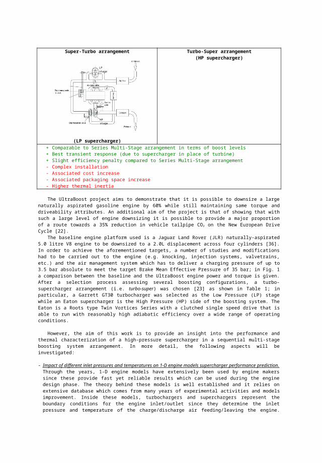
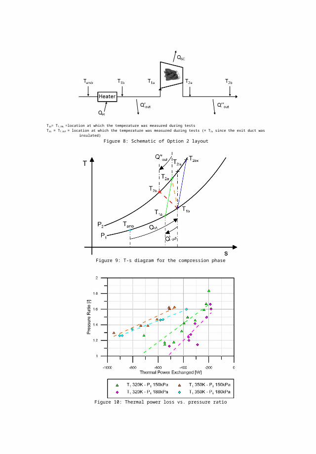