Vickers SystemStak™ SystemStak™ Valves - Eatonpub/@eaton/@hyd/documents/content/...1...
45
649 Revised 11/97 ISO 4401 -05 size, 315 bar (4500 psi) and 120 l/min (32 USgpm) maximum ratings Pressure relief and reducing, sequence, counterbalance, and flow control functions Vickers ® SystemStak™ SystemStak™ Valves
Transcript of Vickers SystemStak™ SystemStak™ Valves - Eatonpub/@eaton/@hyd/documents/content/...1...

649Revised 11/97
ISO 4401 -05 size, 315 bar (4500 psi) and 120 l/min (32 USgpm) maximum ratingsPressure relief and reducing, sequence, counterbalance, and flow control functions
Vickers®
SystemStak™
SystemStak™ Valves
Vickers, Incorporated 1997All Rights Reserved
Table of ContentsIntroduction 1. . . . . . . . . . . . . . . . . . . . . . . . . . . . . . . . . . . . . . . . . . . . . . . . . . . . . . . . . . . . . . . . . . . . . . . . . . . . . . . . . . . . . . . . . . . . . . . . . .
DGMC-5 Single ReliefDGMC2-5 Dual and Crossport Pilot Operated Relief Valves 3. . . . . . . . . . . . . . . . . . . . . . . . . . . . . . . . . . . . . . . . . . . . . . . . . . . . . . .
DGMX2 Pressure Reducing/Relieving Valves 13. . . . . . . . . . . . . . . . . . . . . . . . . . . . . . . . . . . . . . . . . . . . . . . . . . . . . . . . . . . . . . . . . . .
DGMR1 Sequence Valve 17. . . . . . . . . . . . . . . . . . . . . . . . . . . . . . . . . . . . . . . . . . . . . . . . . . . . . . . . . . . . . . . . . . . . . . . . . . . . . . . . . . . . . .
DGMR Counterbalance Valves 20. . . . . . . . . . . . . . . . . . . . . . . . . . . . . . . . . . . . . . . . . . . . . . . . . . . . . . . . . . . . . . . . . . . . . . . . . . . . . . . . .
DGMFN Flow Control Valves 24. . . . . . . . . . . . . . . . . . . . . . . . . . . . . . . . . . . . . . . . . . . . . . . . . . . . . . . . . . . . . . . . . . . . . . . . . . . . . . . . . .
DGMPC Pilot Operated Check Valves 30. . . . . . . . . . . . . . . . . . . . . . . . . . . . . . . . . . . . . . . . . . . . . . . . . . . . . . . . . . . . . . . . . . . . . . . . . .
DGMDC Direct Check Valves 33. . . . . . . . . . . . . . . . . . . . . . . . . . . . . . . . . . . . . . . . . . . . . . . . . . . . . . . . . . . . . . . . . . . . . . . . . . . . . . . . . .
Knob Adjusters 37. . . . . . . . . . . . . . . . . . . . . . . . . . . . . . . . . . . . . . . . . . . . . . . . . . . . . . . . . . . . . . . . . . . . . . . . . . . . . . . . . . . . . . . . . . . . . .
Mounting Surface 38. . . . . . . . . . . . . . . . . . . . . . . . . . . . . . . . . . . . . . . . . . . . . . . . . . . . . . . . . . . . . . . . . . . . . . . . . . . . . . . . . . . . . . . . . . . . DGM**-5DGM**-5NDGM**-5P
Bolt Extender Kits 39. . . . . . . . . . . . . . . . . . . . . . . . . . . . . . . . . . . . . . . . . . . . . . . . . . . . . . . . . . . . . . . . . . . . . . . . . . . . . . . . . . . . . . . . . . . .
Subplates and Blanking Plate 40. . . . . . . . . . . . . . . . . . . . . . . . . . . . . . . . . . . . . . . . . . . . . . . . . . . . . . . . . . . . . . . . . . . . . . . . . . . . . . . . .
Application Data 43. . . . . . . . . . . . . . . . . . . . . . . . . . . . . . . . . . . . . . . . . . . . . . . . . . . . . . . . . . . . . . . . . . . . . . . . . . . . . . . . . . . . . . . . . . . . . Fluid Cleanliness, Fluid Viscosity, Fluids and Seals
1
Introduction
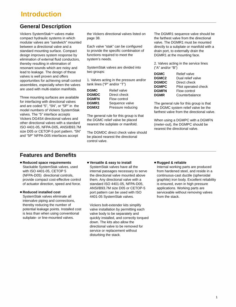
General DescriptionVickers SystemStakTM valves makecompact hydraulic systems in whichmodular valves are “sandwich” mountedbetween a directional valve and astandard mounting surface. Compactdesign improves system response byelimination of external fluid conductors,thereby resulting in elimination ofresonant sounds which are noisy andlead to leakage. The design of thesevalves is well proven and offersopportunities for achieving small controlassemblies, especially when the valvesare used with multi-station manifolds.
Three mounting surfaces are availablefor interfacing with directional valvesand are coded “5”, “5N”, or “5P” in themodel numbers of Vickers SystemStakvalves. The “5” interface acceptsVickers DG4S4 directional valves andother directional valves with a standardISO 4401-05, NFPA-D05, ANSI/B93.7Msize D05 or CETOP-5 port pattern. “5N”and “5P” NFPA-D05 interfaces accept
the Vickers directional valves listed onpage 38.
Each valve “stak” can be configured to provide the specific combination offunctions required to meet the system’s needs.
SystemStak valves are divided into two groups:
1. Valves acting in the pressure and/ortank lines (“P” and/or “T”)
DGMC Relief valveDGMDC Direct checkDGMFN Flow controlDGMR1 Sequence valveDGMX2 Pressure reducing
The general rule for this group is thatthe DGMC relief valve be placednearest the subplate or manifold.
The DGMDC direct check valve shouldbe placed nearest the directional control valve.
The DGMR1 sequence valve should bethe farthest valve from the directionalvalve. The DGMR1 must be mounteddirectly to a subplate or manifold with adrain port, to externally drain theDGMR1 at the mounting face.
2. Valves acting in the service lines(“A” and/or “B”)
DGMC Relief valveDGMC2 Dual relief valveDGMDC Direct checkDGMPC Pilot operated checkDGMFN Flow controlDGMR Counterbalance
The general rule for this group is thatthe DGMC system relief valve be thefarthest valve from the directional valve.
When using a DGMPC with a DGMFN(meter-out), the DGMPC should benearest the directional valve.
Features and Benefits� Reduced space requirements
Stackable SystemStak valves, usedwith ISO 4401-05, CETOP 5(NFPA-D05) directional controls,provide compact cost-effective controlof actuator direction, speed and force.
� Reduced installed costSystemStak valves eliminate allintervalve piping and connections,thereby reducing the number ofpotential leakage points. Installed costis less than when using conventionalsubplate- or line-mounted valves.
� Versatile & easy to installSystemStak valves have all theinternal passages necessary to servethe directional valve mounted abovethem. Any directional valve with astandard ISO 4401-05, NFPA-D05,ANSI/B93.7M size D05 or CETOP-5port pattern can be used with ISO4401-05 SystemStak valves.
Vickers bolt-extender kits simplifyvalve installation by permitting eachvalve body to be separately andquickly installed, and correctly torqueddown. The kits also allow thedirectional valve to be removed forservice or replacement withoutdisturbing the stack.
� Rugged & reliableInternal working parts are producedfrom hardened steel, and reside in acontinuous-cast ductile (spheroidalgraphite) iron body. Excellent reliabilityis ensured, even in high pressureapplications. Working parts areserviceable without removing valvesfrom the stack.
2
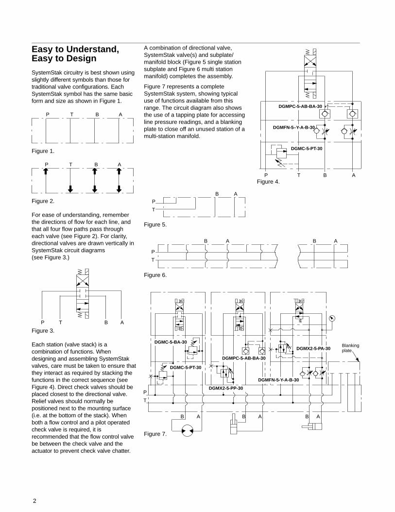
Easy to Understand,Easy to DesignSystemStak circuitry is best shown usingslightly different symbols than those fortraditional valve configurations. EachSystemStak symbol has the same basicform and size as shown in Figure 1.
P T B A
Figure 1.
P T B A
Figure 2.
For ease of understanding, rememberthe directions of flow for each line, andthat all four flow paths pass througheach valve (see Figure 2). For clarity,directional valves are drawn vertically inSystemStak circuit diagrams(see Figure 3.)
P T B A
Figure 3.
Each station (valve stack) is acombination of functions. Whendesigning and assembling SystemStakvalves, care must be taken to ensure thatthey interact as required by stacking thefunctions in the correct sequence (seeFigure 4). Direct check valves should beplaced closest to the directional valve.Relief valves should normally bepositioned next to the mounting surface(i.e. at the bottom of the stack). Whenboth a flow control and a pilot operatedcheck valve is required, it isrecommended that the flow control valvebe between the check valve and theactuator to prevent check valve chatter.
A combination of directional valve,SystemStak valve(s) and subplate/manifold block (Figure 5 single stationsubplate and Figure 6 multi stationmanifold) completes the assembly.
Figure 7 represents a completeSystemStak system, showing typicaluse of functions available from thisrange. The circuit diagram also showsthe use of a tapping plate for accessingline pressure readings, and a blankingplate to close off an unused station of amulti-station manifold.
P
T
B A
Figure 6.
B A
Figure 7.
P
T
B AB AB A
DGMC-5-PT-30
DGMC-5-BA-30
DGMX2-5-PP-30
DGMX2-5-PA-30
DGMPC-5-AB-BA-30
DGMFN-5-Y-A-B-30
Blanking plate
P
T
B A
Figure 5.
P T B A
DGMFN-5–Y-A-B-30
DGMPC-5-AB-BA-30
DGMC-5-PT-30
Figure 4.
3
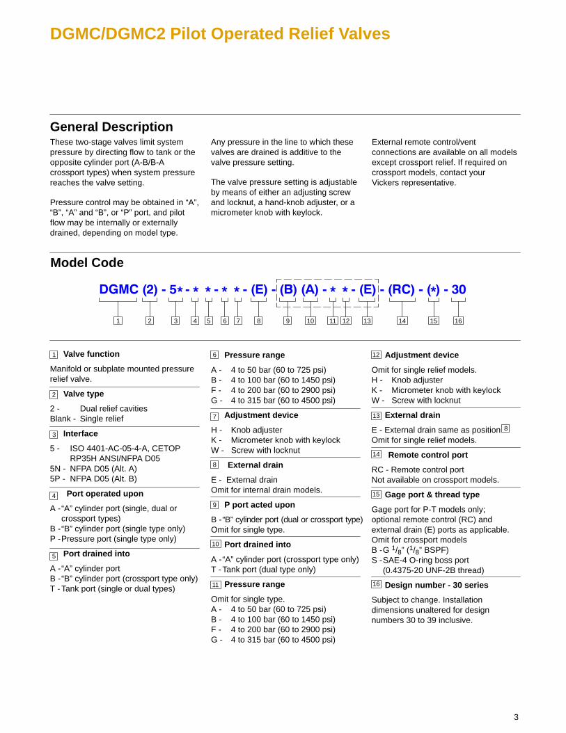
DGMC/DGMC2 Pilot Operated Relief Valves
General DescriptionThese two-stage valves limit systempressure by directing flow to tank or theopposite cylinder port (A-B/B-Acrossport types) when system pressurereaches the valve setting.
Pressure control may be obtained in “A”,“B”, “A” and “B”, or “P” port, and pilotflow may be internally or externallydrained, depending on model type.
Any pressure in the line to which thesevalves are drained is additive to thevalve pressure setting.
The valve pressure setting is adjustableby means of either an adjusting screwand locknut, a hand-knob adjuster, or amicrometer knob with keylock.
External remote control/ventconnections are available on all modelsexcept crossport relief. If required oncrossport models, contact your Vickers representative.
Pressure range
A - 4 to 50 bar (60 to 725 psi)B - 4 to 100 bar (60 to 1450 psi)F - 4 to 200 bar (60 to 2900 psi)G - 4 to 315 bar (60 to 4500 psi)
Adjustment device
H - Knob adjusterK - Micrometer knob with keylockW - Screw with locknut
External drain
E - External drainOmit for internal drain models.
P port acted upon
B -“B” cylinder port (dual or crossport type)Omit for single type.
Port drained into
A -“A” cylinder port (crossport type only)T -Tank port (dual type only)
Pressure range
Omit for single type.A - 4 to 50 bar (60 to 725 psi)B - 4 to 100 bar (60 to 1450 psi)F - 4 to 200 bar (60 to 2900 psi)G - 4 to 315 bar (60 to 4500 psi)
3 4 5 876 9 101 2 11 12 13 14 15 16
Model Code
1
2
Valve function
Manifold or subplate mounted pressurerelief valve.
Valve type
2 - Dual relief cavitiesBlank - Single relief
Interface
5 - ISO 4401-AC-05-4-A, CETOP RP35H ANSI/NFPA D05
5N - NFPA D05 (Alt. A)5P - NFPA D05 (Alt. B)
Port operated upon
A -“A” cylinder port (single, dual orcrossport types)
B -“B” cylinder port (single type only)P -Pressure port (single type only)
Port drained into
A -“A” cylinder portB -“B” cylinder port (crossport type only)T -Tank port (single or dual types)
3
4
5
6
7
8
9
10
12
13
Adjustment device
Omit for single relief models.H - Knob adjusterK - Micrometer knob with keylockW - Screw with locknut
External drain
E - External drain same as position Omit for single relief models.
Remote control port
RC - Remote control portNot available on crossport models.
Gage port & thread type
Gage port for P-T models only;optional remote control (RC) andexternal drain (E) ports as applicable.Omit for crossport modelsB -G 1/8” (1/8” BSPF)S -SAE-4 O-ring boss port
(0.4375-20 UNF-2B thread)
Design number - 30 series
Subject to change. Installationdimensions unaltered for designnumbers 30 to 39 inclusive.
11
14
15
16
8

4
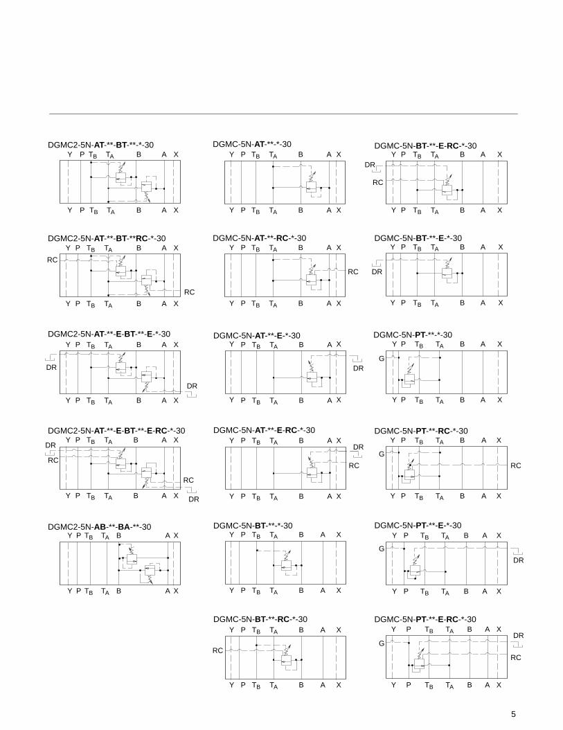
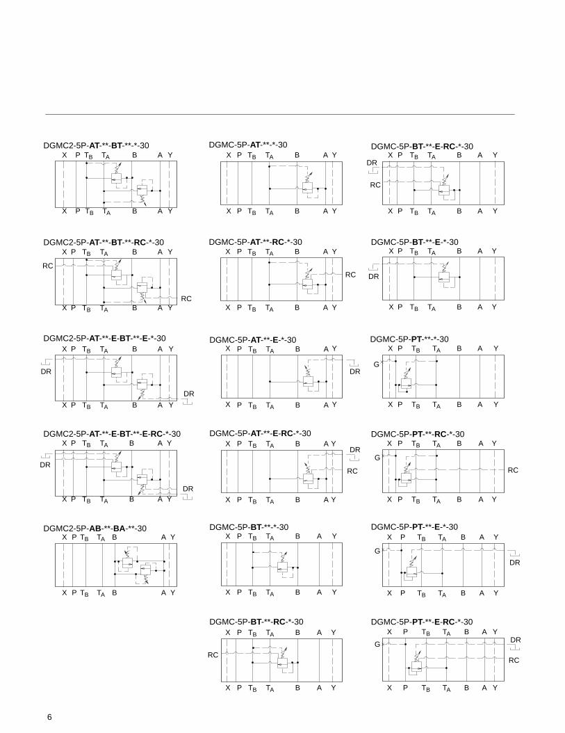
Functional Symbols
P
P
TB
TB
TA
TA
B
B
A
A
DGMC2-5-AT-**-BT-**-*-30
P
P
TB
TB
TA
TA
B
B
A
A
DGMC2-5-AT-**-BT-**RC-*-30
P
P
TB
TB
TA
TA
B
B
A
A
DGMC2-5-AT-**-E-BT-**-E-*-30
P
P
TB
TB
TA
TA
B
B
A
A
DGMC2-5-AT-**-E-BT-**-E-RC-*-30
P
P
TB
TB
TA
TA
B
B
A
A
DGMC-5-AT-**-E-*-30
P
P
TB
TB
TA
TA
B
B
A
A
DGMC-5-AT-**-E-RC-*-30
P
P
TB
TB
TA
TA
B
B
A
A
DGMC-5-PT-**-*-30
P
P
TB
TB
TA
TA
B
B
A
A
DGMC-5-PT-**-RC-*-30
P
P
TB
TB
TA
TA
B
B
A
A
DGMC-5-PT-**-E-*-30
P
P
TB
TB
TA
TA
B
B
A
A
DGMC-5-PT-**-E-RC-*-30
P
P
TB
TB
TA
TA
B
B
A
A
DGMC2-5-AB-**-BA-**-30
P
P
TB
TB
TA
TA
B
B
A
A
DGMC-5-AT-**-*-30
P
P
TB
TB
TA
TA
B
B
A
A
DGMC-5-AT-**-RC-*-30
P
P
TB
TB
TA
TA
B
B
A
A
DGMC-5-BT-**-*-30
P
P
TB
TB
TA
TA
B
B
A
A
DGMC-5-BT-**-RC-*-30
P
P
TB
TB
TA
TA
B
B
A
A
DGMC-5-BT-**-E-*-30
P
P
TB
TB
TA
TA
B
B
A
A
DGMC-5-BT-**-E-RC-*-30
P
P
TB
TB
TA
TA
B
B
A
A
DGMC2-5-AB-**-E-BA-**-E-*-30
DR
DR
RC
DR
DR
RC
DR
RC
G
RC
G
DR
RC
DR
G
G
RC
RC
DR
RC
DR
RC
DR
RC
DR
DR
5
P
P
TB
TB
TA
TA
B
B
A
A
DGMC2-5N-AT-**-BT-**-*-30
P
P
TB
TB
TA
TA
B
B
A
A
DGMC2-5N-AT-**-E-BT-**-E-*-30
P
P
TB
TB
TA
TA
B
B
A
A
DGMC2-5N-AT-**-E-BT-**-E-RC-*-30
P
P
TB
TB
TA
TA
B
B
A
A
DGMC-5N-AT-**-E-*-30
P
P
TB
TB
TA
TA
B
B
A
A
DGMC-5N-AT-**-E-RC-*-30
P
P
TB
TB
TA
TA
B
B
A
A
DGMC-5N-PT-**-*-30
P
P
TB
TB
TA
TA
B
B
A
A
DGMC-5N-PT-**-RC-*-30
P
P
TB
TB
TA
TA
B
B
A
A
DGMC-5N-PT-**-E-*-30
P
P
TB
TB
TA
TA
B
B
A
A
DGMC-5N-PT-**-E-RC-*-30
P
P
TB
TB
TA
TA
B
B
A
A
DGMC2-5N-AB-**-BA-**-30
P
P
TB
TB
TA
TA
B
B
A
A
DGMC-5N-AT-**-*-30
P
P
TB
TB
TA
TA
B
B
A
A
DGMC-5N-AT-**-RC-*-30
P
P
TB
TB
TA
TA
B
B
A
A
DGMC-5N-BT-**-*-30
P
P
TB
TB
TA
TA
B
B
A
A
DGMC-5N-BT-**-RC-*-30
P
P
TB
TB
TA
TA
B
B
A
A
DGMC-5N-BT-**-E-*-30
P
P
TB
TB
TA
TA
B
B
A
A
DGMC-5N-BT-**-E-RC-*-30Y
Y
X
X
P
P
TB
TB
TA
TA
B
B
A
A
DGMC2-5N-AT-**-BT-**RC-*-30Y
Y
X
X
Y
Y
X
X
Y
Y
X
X
Y
Y
X
X
Y
Y
X
X
Y
Y
X
X
Y
Y
X
X
Y
Y
X
X
Y
Y
X
X
Y
Y
X
X
Y
Y
X
X
Y
Y
X
X
Y
Y
X
X
Y
Y
X
X
Y
Y
X
X
Y
Y
X
X
RC
DR
DR
DR
DR
RC
RC
RC
RC
DR
DR
RC
DR
DR
DR
DRG
G
G
G
RC
RC
RCRC
6
P
P
TB
TB
TA
TA
B
B
A
A
DGMC2-5P-AT-**-BT-**-*-30
P
P
TB
TB
TA
TA
B
B
A
A
DGMC2-5P-AT-**-E-BT-**-E-*-30
P
P
TB
TB
TA
TA
B
B
A
A
DGMC2-5P-AT-**-E-BT-**-E-RC-*-30
P
P
TB
TB
TA
TA
B
B
A
A
DGMC-5P-AT-**-E-*-30
P
P
TB
TB
TA
TA
B
B
A
A
DGMC-5P-AT-**-E-RC-*-30
P
P
TB
TB
TA
TA
B
B
A
A
DGMC-5P-PT-**-*-30
P
P
TB
TB
TA
TA
B
B
A
A
DGMC-5P-PT-**-RC-*-30
P
P
TB
TB
TA
TA
B
B
A
A
DGMC-5P-PT-**-E-*-30
P
P
TB
TB
TA
TA
B
B
A
A
DGMC-5P-PT-**-E-RC-*-30
P
P
TB
TB
TA
TA
B
B
A
A
DGMC2-5P-AB-**-BA-**-30
P
P
TB
TB
TA
TA
B
B
A
A
DGMC-5P-AT-**-*-30
P
P
TB
TB
TA
TA
B
B
A
A
DGMC-5P-AT-**-RC-*-30
P
P
TB
TB
TA
TA
B
B
A
A
DGMC-5P-BT-**-*-30
P
P
TB
TB
TA
TA
B
B
A
A
DGMC-5P-BT-**-RC-*-30
P
P
TB
TB
TA
TA
B
B
A
A
DGMC-5P-BT-**-E-*-30
P
P
TB
TB
TA
TA
B
B
A
A
DGMC-5P-BT-**-E-RC-*-30Y
Y
X
X
P
P
TB
TB
TA
TA
B
B
A
A
DGMC2-5P-AT-**-BT-**-RC-*-30Y
Y
X
X
Y
Y
X
X
Y
Y
X
X
Y
Y
X
X
Y
Y
X
X
Y
Y
X
X
Y
Y
X
X
Y
Y
X
X
Y
Y
X
X
Y
Y
X
X
Y
Y
X
X
Y
Y
X
X
Y
Y
X
X
Y
Y
X
X
Y
Y
X
X
Y
Y
X
X
DR
RC
RC
RC
RC DR
DR
DR
DRG
DR
DR
DR
RC
G
RC
G
DR
G
RC
DR
RC
7
Operating DataP
ress
ure
Dro
p ba
r
Pre
ssur
e D
rop
psi
15
10
5
200
150
100
50
0 0
Flow l/min
Flow USgpm
20 40 60 80 100 120
5 10 15 20 25 30
DGMC-5 and DGMC2-5 Insertion Loss
Pre
ssur
e ba
r
Pre
ssur
e ps
i
20
15
10
250
200
150
100
0 0
Flow l/min
Flow USgpm
20 40 60 80 100 120
5 10 15 20 25 30
DGMC-5 and DGMC2-5 Vented Pressure (RC models only) (Not applicable for crossport models)
550
Pre
ssur
e ba
r
Pre
ssur
e ps
i
200
150
100
4000
3000
2000
0 0
Flow l/min
Flow USgpm
20 40 60 80 100 120
5 10 15 20 25 30
DGMC-5 and DGMC2-5 Pressure Override
501000
300
350
250
5000
1
2
3
G
F
B
A
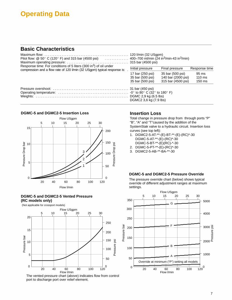
The vented pressure chart (above) indicates flow from controlport to discharge port over relief element.
Basic CharacteristicsMaximum flow: 120 l/min (32 USgpm). . . . . . . . . . . . . . . . . . . . . . . . . . . . . . . . . . . . . . . . . . . . . . . . . Pilot flow: @ 50� C (120� F) and 315 bar (4500 psi) 400–700 ml/min (24 in3/min-43 in3/min). . . . . . . . . . . . . . Maximum operating pressure: 315 bar (4500 psi). . . . . . . . . . . . . . . . . . . . . . . . . . . . . . . . . . . . Response time: For conditions of 5 liters (300 in3) of oil undercompression and a flow rate of 120 l/min (32 USgpm) typical response is: .
Pressure overshoot: 31 bar (450 psi). . . . . . . . . . . . . . . . . . . . . . . . . . . . . . . . . . . . . . . . . . . . Operating temperature: -0� to 80� C (32� to 180� F). . . . . . . . . . . . . . . . . . . . . . . . . . . . . . . . . . . . . . . . . Weights: DGMC 2,9 kg (6.5 lbs). . . . . . . . . . . . . . . . . . . . . . . . . . . . . . . . . . . . . . . . . . . . . . . . . . . . . .
DGMC2 3,6 kg (7.9 lbs)
The pressure override chart (below) shows typicaloverride of different adjustment ranges at maximumsettings.
Insertion LossTotal change in pressure drop from through ports “P”“B”, “A” and “T”caused by the addition of theSystemStak valve to a hydraulic circuit. Insertion losscurves (see top left):1. DGMC2-5-AT-**-(E)-BT-**-(E)-(RC)*-30
DGMC-5-AT-**-(E)-(RC)*-30DGMC-5-BT-**-(E)(RC)-*-30
2. DGMC-5-PT-**-(E)-(RC)*-303. DGMC2-5-AB-**-BA-**-30
Override at minimum (“P”) setting all models
Initial pressure Final pressure Response time
17 bar (250 psi)35 bar (500 psi)35 bar (500 psi)
35 bar (500 psi)140 bar (2000 psi)315 bar (4500 psi)
95 ms110 ms150 ms
8
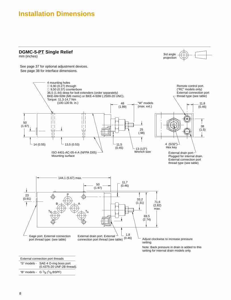
Installation Dimensions
14 (0.55)
DGMC-5-PT Single Relief
50(1.97)
25(.98)
48(1.89)
“W” models (max. ext.)
Wrench size13 (1/2”)
11,5(0.45)
ISO 4401-AC-05-4-A (NFPA D05)Mounting surface
13,5 (0.53)
4 mounting holes ∅ 6,90 (0.27) through ∅ 9,50 (0.37) counterbore 36,5 (1.44) deep for bolt extenders (order separately)BKE-6M-50M (M6 metric) or BKE-4-50M (.2500-20 UNC).Torque: 11,3-14,7 Nm (100-130 lb. in.)
144,1 (5.67) max.
23(0.91)
50(1.97)
11,7(0.46)
33,2(1.31)
69,5(2.74)
71,6(2.82)max.
38(1.5)
11,8(0.46)
1,8(0.46) Adjust clockwise to increase pressure
setting.
Note: Back pressure in drain is added to thissetting for internal drain models only.
External drain port. External connection port thread (see table)
External drain port. Plugged for internal drain.External connection portthread type (see table)
Remote control port.(“RC” models only)External connection portthread type (see table)
Hex key4 (5/32”)
Gage port. External connectionport thread type: (see table)
TB
B
P
A
TA
mm (inches)
“S” models - SAE-4 O-ring boss port(0.4375-20 UNF-2B thread).
“B” models - G 1/8 (1/8 BSPF)
External connection port threads
3rd angleprojection
See page 38 for interface dimensions.See page 37 for optional adjustment devices.
9
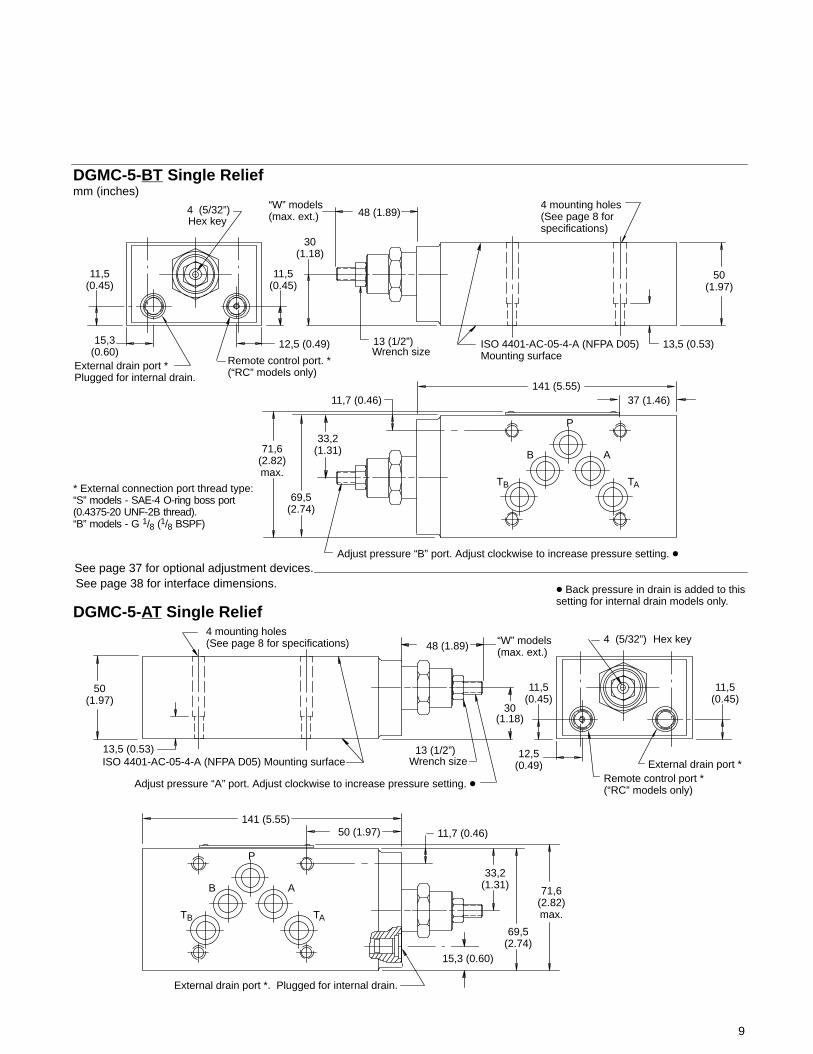
ISO 4401-AC-05-4-A (NFPA D05) Mounting surface
4 mounting holes (See page 8 forspecifications)
Adjust pressure “A” port. Adjust clockwise to increase pressure setting. �
DGMC-5-BT Single Relief
50(1.97)
30(1.18)
48 (1.89)“W” models (max. ext.)
Wrench sizeISO 4401-AC-05-4-A (NFPA D05)Mounting surface
13,5 (0.53)
141 (5.55)37 (1.46)11,7 (0.46)
33,2(1.31)
69,5(2.74)
71,6(2.82)max.
Adjust pressure “B” port. Adjust clockwise to increase pressure setting. �
External drain port * Plugged for internal drain.
Remote control port. *(“RC” models only)
Hex key
TA
B
P
A
TB
� Back pressure in drain is added to thissetting for internal drain models only.
11,5(0.45)
15,3(0.60)
11,5(0.45)
12,5 (0.49)
50(1.97)
30(1.18)
48 (1.89) “W” models (max. ext.)
Wrench size13,5 (0.53)
4 mounting holes (See page 8 for specifications)
141 (5.55)50 (1.97) 11,7 (0.46)
33,2(1.31)
69,5(2.74)
71,6(2.82)max.
External drain port *Remote control port * (“RC” models only)
Hex key
TB
B
P
A
TA
11,5(0.45)
11,5(0.45)
12,5(0.49)
DGMC-5-AT Single Relief
External drain port *. Plugged for internal drain.
mm (inches)
4 (5/32”)
13 (1/2”)
13 (1/2”)
4 (5/32”)
15,3 (0.60)
* External connection port thread type: “S” models - SAE-4 O-ring boss port(0.4375-20 UNF-2B thread).“B” models - G 1/8 (1/8 BSPF)
See page 38 for interface dimensions.See page 37 for optional adjustment devices.

10
* Remote control port. Both ends(“RC” models only)
DGMC2-5-AT-**-BT-**-30Dual Relief
50(1.97)
30(1.18)
48(1.89)
“W” models (max. ext.)typ. both ends
ISO 4401-AC-05-4-A (NFPA D05)Mounting surface
13,5(0.53)
153,9 (6.06)
50(1.97)
11,7(0.46)
33,2(1.31)71,6
(2.82)max.
Adjust pressure “B” port. Adjust clockwise to increase pressure setting. �
* External connection port thread type: “S” models - SAE-4 O-ring boss port (0.4375-20 UNF-2B thread). “B” models - G 1/8 (1/8 BSPF)
TA
B
P
A
TB
� Back pressure in drain is added to thissetting for internal drain models only.
Wrench size both ends
33,2(1.31)
69,5(2.74)
15,3(0.60)
bothends
11,5(0.45)
bothends
bothends
12,5 (0.49)both ends
Hex key
External drain port *(both ends). Plugged for internal drain.
Adjust pressure “A” port. Adjustclockwise to increase pressuresetting. �
mm (inches)
13 (1/2”)
4 (5/32”)
4 mounting holes ∅ 6,9 (0.27) through ∅ 9,50 (0.37) counterbore 36,5 (1.44) deep for bolt extenders(order separately)BKE-6M-50M (M6 metric) orBKE-4-50M (.2500-20 UNC).Torque: 11,3-14,7 Nm (100-130 lb. in.)
* Remote control port. Both ends(“RC” models only)
15 in model code
See page 38 for interface dimensions.See page 37 for optional adjustment devices.

11
DGMC2-5-AB-**-BA-**-30Dual Crossport Relief
60(2.36)
20(0.79)
45,6(1.71)
“W” models (max. ext.)typ. both ends
ISO 4401-AC-05-4-A (NFPA D05)Mounting surface
14,0 (0.55)
128 (5.04)37
(1.46)11,7
(0.46)
31,3(1.23)71,6
(2.82)max.
Adjust pressure “A” port. Adjust clockwise to increase pressure setting.
TA
B
P
A
TB
Wrench sizeboth ends
69,5(2.74)
Hex key
Adjust pressure “B” port. Adjustclockwise to increase pressure setting.
mm (inches)
40(1.57)
4 mounting holes ∅ 6,90 (0.27) through. ∅ 9,50 (0.37) counterbore 46,5 (1.83) deep for bolt extenders (order separately)BKE-6M-60M (M6 metric) orBKE-4-60M (.2500-20 UNC). Torque: 11,3-14,7 Nm (100-130 lb. in.)
13 (1/2”)
4 (5/32”)
“S” models - SAE-4 O-ring boss port(0.4375-20 UNF-2B thread).
“B” models - G 1/8 (1/8 BSPF)
External drain port threads
46(1.81)
External drain (See table)
External drain (See table)
B A
See page 38 for interface dimensions.See page 37 for optional adjustment devices.
12
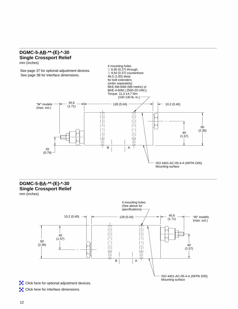
DGMC-5-AB-**-(E)-*-30Single Crossport Relief
60(2.36)
20(0.79)
45,6(1.71)
“W” models (max. ext.)
mm (inches)
40(1.57)
DGMC-5-BA-**-(E)-*-30Single Crossport Relief
60(2.36) 40
(1.57)
45,6(1.71)
“W” models (max. ext.)
mm (inches)
40(1.57)
B A
B A
10,2 (0.40)
10,2 (0.40)
128 (5.04)
128 (5.04)
4 mounting holes (See above forspecifications)
4 mounting holes ∅ 6,90 (0.27) through. ∅ 9,50 (0.37) counterbore 46,5 (1.83) deep for bolt extenders (order separately)BKE-6M-60M (M6 metric) orBKE-4-60M (.2500-20 UNC). Torque: 11,3-14,7 Nm (100-130 lb. in.)
ISO 4401-AC-05-4-A (NFPA D05)Mounting surface
ISO 4401-AC-05-4-A (NFPA D05)Mounting surface
Click here for interface dimensions.
Click here for optional adjustment devices.
See page 38 for interface dimensions.See page 37 for optional adjustment devices.

13
DGMX2 Pressure Reducing/Relieving Valves
General DescriptionThese two-stage spool valves maintaina reduced outlet pressure againstvariations in inlet pressure.
These valves are able to act as reliefvalves (at 50% of maximum flow) toprevent excess pressure beingdeveloped when an actuator is subjectto a reactive load. Relief flow is directedto the “TB” port. Therefore, for the relieffunction to operate, all componentsabove this DGMX2 module must containthe “TB” port, and the directional valvemust have the “TB” bypass feature.
Pilot control may be from the “P”, “A”, or“B” port. Pilot drain flow may be directed
internally to tank port “TA”, or externallyout of the valve body.
Any pressure in the line to which thesevalves are drained is additive to thevalve pressure setting.
The valve pressure setting is adjustableby means of either an adjusting screwcontaining an internal hex, ahand-adjust knob, or a micrometer knobwith keylock.
Different spring ratings cover an overallpressure range from 2 to 315 bar(30-4500 psi).
The metering spool element in thisdesign is always positioned in the “P”
line (see symbols on page14). Theconnection of the pilot control linedetermines at which port the reducedpressure is obtained. For example:
“PP” pilot for reduced pressure in “P” port
“PA” pilot for reduced pressure in “A” port
“PB” pilot for reduced pressure in “B” port
The “A” and “B” line models provide forreduced pressure when “P” is connectedto “A” or “B”. It allows free flow throughthe service port when connected to “T”(all via a four-way directional valve).
3 4 5 876 91 2
Model Code
1
2
Valve functionManifold or subplate mountedreducing/relieving valve.
Interface5 - ISO 4401-AC-05-4-A, CETOP 5
RP35A size 5 ANSI/NFPA D055N - NFPA D05 (Alt. A)5P - NFPA D05 (Alt. B)
Port operated uponP -Pressure port
Pilot controlA - Cylinder port AB - Cylinder port BP - Pressure port
3
5
6
7
Pressure range
A - 2,0 to 50 bar (30 to 725 psi)B - 8,5 to 100 bar (125 to 1450 psi)F - 8,5 to 200 bar (125 to 2900 psi)G - 8,5 to 315 bar (125 to 4500 psi)
Adjustment device
H - Knob adjusterK - Micrometer knob with keylockW - Screw with locknut
External drain
E - External drainOmit for internal drain models.
Remote control
Omit if not required.
Gage port & thread type
Gage port (all models),external drain (E)B -G 1/8” (1/8” BSPF)S -SAE-4 O-ring boss port
(0.4375-20 UNF-2B thread)
Design mumber - 30 series
Subject to change. Installationdimensions unaltered for designnumbers 30 to 39 inclusive.
10
9
4
10
8

14
Functional Symbols
TB
TB
TB
TB
TA
TA
TA
P
P
TB
TB
TA
TA
B
B
A
A
DGMX2-5-PP-**-E-*-30 DGMX2-5-PA-**-E-30
P
P
TB
TB
TA
TA
B
B
A
A
DGMX2-5-PP-**-*-30P
P
TB
TB
TA
TA
B
B
A
A
DGMX2-5-PB-**-*-30
P
P
TB
TB
TA
TA
B
B
A
A
DGMX2-5-PB-**-E-30P
P
TB
TB
TA
TA
B
B
A
A
P TB
P
P
TB
TB
TA
TA
B
B
A
A
DGMX2-5-PA-**-*-30P TB
P
P
TB
TB
B
B
A
A
DGMX2-5-PP-**-E-RC-*-30 DGMX2-5-PA-**-E-RC-30
P
P
TB
TB
TA B
B
A
A
DGMX2-5-PP-**-RC-*-30P
P
TB
TB
TA
TA
B
B
A
A
DGMX2-5-PB-**-RC-*-30
P
P
TB
TB
TA
TA
B
B
A
A
DGMX2-5-PB-**-E-RC-30P
P
TB
TB
TA
TA
B
B
A
A
P TB
P
P
TB
TB
TA
TA
B
B
A
A
DGMX2-5-PA-**-RC-*-30P TB
P
P TB
TA
TA
B
B
A
A
DGMX2-5N-PP-**-*-30X
X
Y
Y
P
P
TB
TB
TA
TA
B
B
A
A
DGMX2-5N-PP-**-E-*-30X
X
Y
Y
P
P
TB
TB
TA
TA
B
B
A
A
DGMX2-5N-PA-**-*-30P TB X
X
Y
Y
DGMX2-5N-PA-**-E-*-30P
P
TB
TB
TA
TA
B
B
A
A
X
X
Y
Y
DGMX2-5N-PB-**-30P
P
TB
TB
TA
TA
B
B
A
A
Y
Y
X
X
DGMX2-5N-PB-**-E-30P
P
TB
TB
TA
TA
B
B
A
A
Y
Y
X
X
P
P
TA
TA
B
B
A
A
DGMX2-5P-PP-**-*-30X
X
Y
Y
P
P
TB
TB
TA
TA
B
B
A
A
DGMX2-5P-PP-**-E-*-30X
X
Y
Y
P
P
TB
TB
TA
TA
B
B
A
A
DGMX2-5P-PA-**-*-30P TBX
X
DGMX2-5P-PA-**-E-*-30P TA
TA
B
B
A
A
X
X
DGMX2-5P-PB-**-30P
P
TB
TB
TA
TA
B
B
A
A
Y
Y
X
X
DGMX2-5P-PB-**-E-30P
P
TB
TB
TA
TA
B
B
A
A
Y
Y
X
X
Y
Y
Y
YTB
G
G
DR
G
G
DR
G
G
DR
RC
RC
DR
DR
G
G
G
G
G
G
DR
DR
DR
DR DR
DR
DR
RCG
G
G
G
G
G G
G
G
G
G
G
RCRC
RC
15
Operating Data
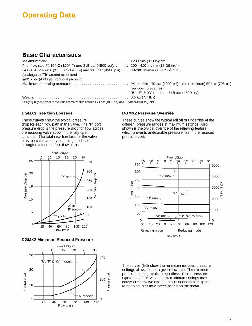
Basic CharacteristicsMaximum flow: 120 l/min (32 USgpm). . . . . . . . . . . . . . . . . . . . . . . . . . . . . . . . . . . . . . . . . . . Pilot flow rate @ 50� C (120� F) and 315 bar (4500 psi): 290 - 420 ml/min (18-26 in3/min). . . . . . . Leakage flow rate @ 50� C (120� F) and 315 bar (4500 psi): 80-200 ml/min (15-12 in3/min). . . (Leakage to “Tb” around spool land@315 bar (4500 psi) reduced pressure) Maximum operating pressure: “A” models - 70 bar (1000 psi) * (inlet pressure) 50 bar (725 psi). . . . . . . . . . . . . . . . . . . . . . . . . . . . . .
(reduced pressure)“B”, “F” & “G” models - 315 bar (4500 psi)
Weight: 3,5 kg (7.7 lbs). . . . . . . . . . . . . . . . . . . . . . . . . . . . . . . . . . . . . . . . . . . . . . . . . * Slightly higher pressure override characteristics between 70 bar (1000 psi) and 315 bar (4500 psi) inlet.
DGMX2 Insertion Lossess
Pre
ssur
e ba
r
Pre
ssur
e ps
i
200
150
100
4000
3000
2000
0 0
Flow l/min
Flow USgpm
20 40 60 80 100 120
5 10 15 20 25 30
DGMX2 Pressure Override
501000
300
350
250
5000
Pre
ssur
e D
rop
bar
Pre
ssur
e D
rop
psi
15
10
100
0 0
Flow l/min
Flow USgpm
20 40 60 80 100 120
5 10 15 20 25 30
550
25
20
150
200
250
300
350
These curves show the typical pressuredrop for each flow path in the valve. The “P” portpressure drop is the pressure drop for flow acrossthe reducing valve spool in the fully opencondition. The total insertion loss for the valvemust be calculated by summing the lossesthrough each of the four flow paths.
“A” or“B” port
“P” port
“T” port
These curves show the typical roll off or underride of thedifferent pressure ranges at maximum settings. Alsoshown is the typical override of the relieving featurewhich prevents undesirable pressure rise in the reducedpressure port.
10 5 015
0204060
Relieving mode Reducing mode
“G” max.
“F” max.
“B” max.
Pre
ssur
e ba
r
Pre
ssur
e ps
i
30
20
10
200
0 0
Flow l/min
Flow USgpm
20 40 60 80 100 120
5 10 15 20 25 30
400
“A” models
“B”, “F” & “G” models
DGMX2 Minimum Reduced Pressure
The curves (left) show the minimum reduced pressuresettings allowable for a given flow rate. The minimumpressure setting applies regardless of inlet pressure.Operation of the valve below minimum settings maycause erratic valve operation due to insufficient springforce to counter flow forces acting on the spool.
“A” min. “B”, “F”, “G” min.
“A” max.
16
Installation Dimensions
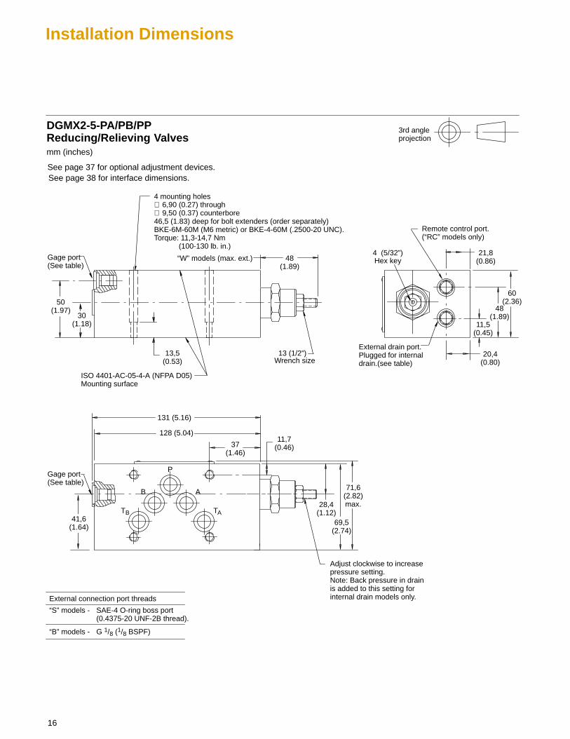
48(1.89)
Gage port(See table)
4 mounting holes ∅ 6,90 (0.27) through ∅ 9,50 (0.37) counterbore 46,5 (1.83) deep for bolt extenders (order separately)BKE-6M-60M (M6 metric) or BKE-4-60M (.2500-20 UNC). Torque: 11,3-14,7 Nm (100-130 lb. in.)
DGMX2-5-PA/PB/PPReducing/Relieving Valves
30(1.18)
50(1.97)
“W” models (max. ext.)
Wrench size
11,5(0.45)
ISO 4401-AC-05-4-A (NFPA D05)Mounting surface
13,5(0.53)
131 (5.16)
37(1.46)
11,7(0.46)
28,4(1.12)
69,5(2.74)
71,6(2.82)max.
20,4(0.80)
Adjust clockwise to increasepressure setting.Note: Back pressure in drainis added to this setting forinternal drain models only.
TB
B
P
A
TA
mm (inches)
128 (5.04)
41,6(1.64)
“S” models - SAE-4 O-ring boss port(0.4375-20 UNF-2B thread).
“B” models - G 1/8 (1/8 BSPF)
External connection port threads
Gage port(See table)
3rd angleprojection
13 (1/2”)
48(1.89)
21,8(0.86)
External drain port. Plugged for internaldrain.(see table)
Remote control port.(“RC” models only)
Hex key4 (5/32”)
60(2.36)
See page 38 for interface dimensions.See page 37 for optional adjustment devices.
17
DGMR1 Internal Pilot Operated Sequence Valves
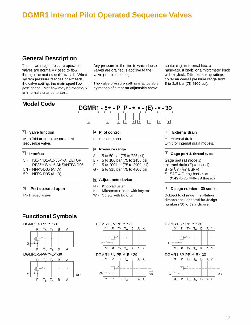
General DescriptionThese two-stage pressure operatedvalves are normally closed to flowthrough the main spool flow path. Whensystem pressure reaches or exceedsthe valve setting, the main spool flowpath opens. Pilot flow may be externallyor internally drained to tank.
Any pressure in the line to which thesevalves are drained is additive to thevalve pressure setting.
The valve pressure setting is adjustableby means of either an adjustable screw
containing an internal hex, ahand-adjust knob, or a micrometer knobwith keylock. Different spring ratingscover an overall pressure range from 5 to 315 bar (75-4500 psi).
3 4 5 876 91 2
Model Code
1
2
Valve function
Manifold or subplate mountedsequence valve.
Interface
5 - ISO 4401-AC-05-4-A, CETOP RP35H Size 5 ANSI/NFPA D05
5N - NFPA-D05 (Alt A)5P - NFPA-D05 (Alt B)
Port operated upon
P - Pressure port
3
4
5
6
Pilot control
P - Pressure port
Pressure range
A - 5 to 50 bar (75 to 725 psi)B - 5 to 100 bar (75 to 1450 psi)F - 5 to 200 bar (75 to 2900 psi)G - 5 to 315 bar (75 to 4500 psi)
Adjustment device
H - Knob adjusterK - Micrometer knob with keylockW - Screw with locknut
External drain
E - External drainOmit for internal drain models.
Gage port & thread type
Gage port (all models),external drain (E) (optional).B -G 1/8” (1/8” BSPF)S -SAE-4 O-ring boss port
(0.4375-20 UNF-2B thread)
Design number - 30 series
Subject to change. Installationdimensions unaltered for designnumbers 30 to 39 inclusive.
9
7
8
Functional Symbols
P
P
TB
TB
TA
TA
B
B
A
A
DGMR1-5-PP-**-*-30
P
P
TB
TB
TA
TA
B
B
A
A
X
X
Y
Y
DGMR1-5N-PP-**-E-*-30P
P
TB
TB
TA
TA
B
B
A
A
DGMR1-5-PP-**-E-*-30
P
P
TB
TB
TA
TA
B
B
A
A
X
X
Y
Y
DGMR1-5N-PP-**-*-30
P
P
TB
TB
TA
TA
B
B
A
A
X
X
Y
Y
DGMR1-5P-PP-**-E-*-30
P
P
TB
TB
TA
TA
B
B
A
A
X
X
Y
Y
DGMR1-5P-PP-**-*-30
G
G
G
G
G
GDR DR DR
18
Operating Data
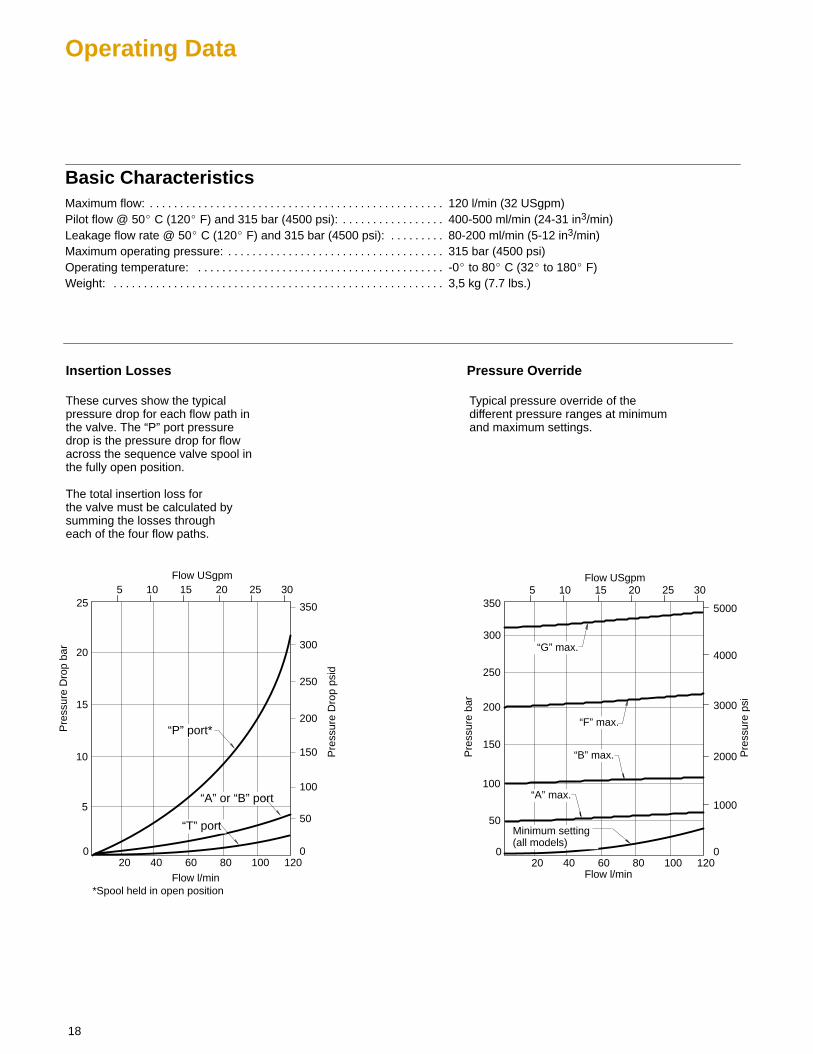
Basic CharacteristicsMaximum flow: 120 l/min (32 USgpm). . . . . . . . . . . . . . . . . . . . . . . . . . . . . . . . . . . . . . . . . . . . . . . . . Pilot flow @ 50� C (120� F) and 315 bar (4500 psi): 400-500 ml/min (24-31 in3/min). . . . . . . . . . . . . . . . . Leakage flow rate @ 50� C (120� F) and 315 bar (4500 psi): 80-200 ml/min (5-12 in3/min). . . . . . . . . Maximum operating pressure: 315 bar (4500 psi). . . . . . . . . . . . . . . . . . . . . . . . . . . . . . . . . . . . Operating temperature: -0� to 80� C (32� to 180� F). . . . . . . . . . . . . . . . . . . . . . . . . . . . . . . . . . . . . . . . . Weight: 3,5 kg (7.7 lbs.). . . . . . . . . . . . . . . . . . . . . . . . . . . . . . . . . . . . . . . . . . . . . . . . . . . . . . .
Pre
ssur
e D
rop
bar
Pre
ssur
e D
rop
psid
15
10
100
0 0
Flow l/min
Flow USgpm
20 40 60 80 100 120
5 10 15 20 25 30
Insertion Losses
550
25
20
Pre
ssur
e ba
r
Pre
ssur
e ps
i
200
150
100
4000
3000
2000
0 0
Flow l/min
Flow USgpm
20 40 60 80 100 120
5 10 15 20 25 30
Pressure Override
501000
300
350
250
5000
150
200
250
300
350
These curves show the typicalpressure drop for each flow path inthe valve. The “P” port pressuredrop is the pressure drop for flowacross the sequence valve spool inthe fully open position.
Typical pressure override of thedifferent pressure ranges at minimumand maximum settings.
“A” or “B” port
“P” port*
“T” port
“G” max.
“F” max.
“B” max.
“A” max.
Minimum setting(all models)
*Spool held in open position
The total insertion loss forthe valve must be calculated bysumming the losses througheach of the four flow paths.

19
Installation Dimensions
* Gage port. Externalconnection port thread
DGMR1-5-PP-**-30Sequence Valve
60(2.36)
10(0.39)
30,5(1.20)
48(1.89)
“W” models (max. ext.)
Wrench size
11,5(0.45)
ISO 4401-AC-05-4-A (NFPA D05)Mounting surface
13,5(0.53)
4 mounting holes ∅ 6,9 (0.27) through ∅ 9,50 (0.37) counterbore 46,5 (1.83) deep for bolt extenders (order separately)BKE-6M-60M (M6 metric) orBKE-4-60M (.2500-20 UNC). Torque: 11,3-14,7 Nm (100-130 lb. in.)
130(5.12)
37(1.46)
11,7(0.46)
28,4(1.12)
69,5(2.74)
71,6(2.82)max.
20,4(0.80)
Adjust clockwise to increase pressure setting.
Note: Back pressure in drainis added to this setting forinternal drain models only.
*External drain port. Plugged for internal drain
* Gage port. Externalconnection port thread
TB
B
P
A
TA
mm (inches)
128(5.04)
3rd angleprojection
13 (1/2”)
“S” models - SAE-4 O-ring boss port(0.4375-20 UNF-2B thread).
“B” models - G 1/8 (1/8 BSPF)
*External drain and gage port threads
Hex key 4 (5/32”)
See page 38 for interface dimensions.See page 37 for optional adjustment devices.

20
DGMR Counterbalance Valves
General DescriptionVickers SystemStak counterbalancevalves provide continuous protection frompump cavitation and prevent an actuatorfrom running ahead of the pump supply.
These valves also provide thermal reliefprotection in closed systems.
NOTECounterbalance valves adjust in theopposite direction of other pressurecontrol valves. Turning the adjustercounterclockwise increases the valvesetting. Turning the adjustmentclockwise lowers the pressure setting,releasing the load.
Drain
Any pressure in the line to which thesevalves are drained is additive to thevalve pressure setting.
Pilot pressure CalculationTo open the counterbalance valve byremote control (referring to functionalsymbols below):
For 4:1 ratio (typically for cylinder loadcontrol), nominal pilot pressure at Port B =
Cracking pressure + (5 x Port A1 pressure) – Port A pressure
4
For 10:1 ratio (typically for hydraulic motorcontrol), nominal pilot pressure at Port B =
Cracking pressure + (11x Port A1 pressure) – Port A pressure
10
Functional Symbols
A1
A
P
P
T
T
B1
DGMR-5-A*-FW-B*-FW-30
B
A1
A
P
P
T
T
B
DGMR-5-A*-FW-30
B
A
A
P
P
T
T
B1
DGMR-5-B*-FW-30
B
3 4 5 876 91 2
Model Code
1
2
Valve function
Manifold or subplate mountedcounterbalance valve.
Interface
5 - ISO 4401-AC-05-4-A, CETOP 5 RP35H, Size 5 ANSI/NFPA D05
Port operated upon
A -Counterbalance in A, piloted from BB -Counterbalance in B, piloted from A
Pilot ratio
1 - 4:12 - 10:1
3
5
6
7
Pressure range
F -60 to 210 bar (900 to 3000 psi)
Adjustment device
H - Knob adjusterC - Cap over screwW - Screw with locknut
Port acted upon(Omit for single type.)
B -Counterbalance in B, piloted from A
Pilot ratio(Omit for single type.)
1 - 4:12 - 10:1
Pressure range(Omit for single type.)
F - 60 to 210 bar (900 to 3000 psi)
Adjustment device(Omit for single type.)
H - Knob adjusterC - Cap over screwW - Screw with locknut
Design number - 30 series
Subject to change. Installationdimensions unaltered for designnumbers 30 to 39 inclusive.
10
9
10 11
4 8
11

21
Operating Data
Basic CharacteristicsMaximum operating pressure: 315 bar (4500 psi). . . . . . . . . . . . . . . . . . . . . . . . . . . . . . . . . . . . Maximum flow rate: 120 l/min (32 USgpm). . . . . . . . . . . . . . . . . . . . . . . . . . . . . . . . . . . . . . . . . . . . . Load holding leakage @70% of pressure setting 0.35 ml/min.. . . . . . . . . . . . . . . . . . . . Cracking Pressure Adjustment Range: 60-210 bar (900-3000 psi). . . . . . . . . . . . . . . . . . . . . . . . . . . . Pilot Ratios: 4:1, 10:1. . . . . . . . . . . . . . . . . . . . . . . . . . . . . . . . . . . . . . . . . . . . . . . . . . . Leakage: 5 drops/min, Port A to Port A1 at 70% of crack setting.. . . . . . . . . . . . . . . . . . . . . . . . . . . . . . . . . . . . . . . . . . . . . . . . . . . . . . Temperature Range: -40� to 80� C (-40� to 180� F). . . . . . . . . . . . . . . . . . . . . . . . . . . . . . . . . . . . . . . . . . . . Weight: 4,5 kg (10 lbs). . . . . . . . . . . . . . . . . . . . . . . . . . . . . . . . . . . . . . . . . . . . . . . . . . . . . . .
DGMR Performance Curves
Pre
ssur
e D
rop
bar
Pre
ssur
e D
rop
psid
30
20 300
0 0
Flow l/min
Flow USgpm
20 40 60 80 100 120
5 10 15 20 25 30
10 150
60
40
450
600
750
These curves show the typical pressuredrop for each flow path in the valve forfluid viscosity range 21-32 cSt(100-150 SSU).
The total insertion loss for the valve iscalculated by summing the losses througheach of the four flow paths.
50
4
3
Pre
ssur
e D
rop
psid
4
0
Flow l/min
Flow USgpm
40 80
10 20
2
201
30
120
2
40
1 “P” port for all models.“A” port of DGMR-5-B*-30 “B” port of DGMR-5-A*-30
2 “T” port for all models.
3 Free flow through service portof counterbalance.
4 Piloted port open throughservice port of counterbalance.
Insertion Losses
20 60 1000
3
1
10
30
50
Pre
ssur
e D
rop
bar
5 15 25

22
Installation Dimensions
DGMR-5-A*-FW-B*-FW-30Dual Counterbalanceon A & B Ports
60(2.36)
65,6(2.58)
“W” models (max. ext.)both ends
Wrench sizeISO 4401-AC-05-4-A (NFPA D05)Mounting surface
4 mounting holes ∅ 6,90 (0.27) through ∅ 9,50 (0.37) counterbore 46,5 (1.83) deep for bolt extenders (order separately) BKE-6M-60M (M6 metric) or BKE-4-60M (.2500-20 UNC). Torque: 11,3-14,7 Nm (100-130 lb. in.)
155,5(6.12)
50(1.97)
11,7(0.46)
33,2(1.31)
69,5(2.74)
71,6(2.82)
mm (inches)
��
�
�
�
21,5(0.85)
13,5(0.53)
3rd angleprojection
Hex key4 (5/32”)
13 (1/2”)
Adjust counterclockwise to increasepressure setting.
��
See page 38 for interface dimensions.See page 37 for optional adjustment devices.

23
DGMR-5-A*-FW-30Counterbalance Port A,Piloted from B
65,6(2.58)
“W” models (max. ext.)
ISO 4401-AC-05-4-A (NFPA D05)Mounting surface
4 mounting holes(see page 22)
142,6 (5.61)50
(1.97)
11,7(0.46)
33,2(1.31)
69,5(2.74)
71,6(2.82)
Hex key
mm (inches)
��
�
�
�
��
21,5(0.85)
DGMR-5-B*-FW-30Counterbalance Port B,Piloted from A
60(2.36)
������ ��������������������
65,6(2.58)
“W” models (max. ext.)
Wrench size
ISO 4401-AC-05-4-A (NFPA D05)Mounting surface
142,6 (5.61) 11,7(0.46)
33,2(1.31)
69,5(2.74)
71,6(2.82)
Hex key
�
�
�
21,5(0.85)
60(2.36)
4 mounting holes (see page 23)
������ ��������������������
Wrench size13 (1/2”)
4 (5/32”)
4 (5/32”)
13 (1/2”)
Adjust counterclockwise toincrease pressure setting.
Adjust counterclockwise toincrease pressure setting.
37 (1.46)
�� ��
See page 38 for interface dimensions.See page 37 for optional adjustment devices.
24
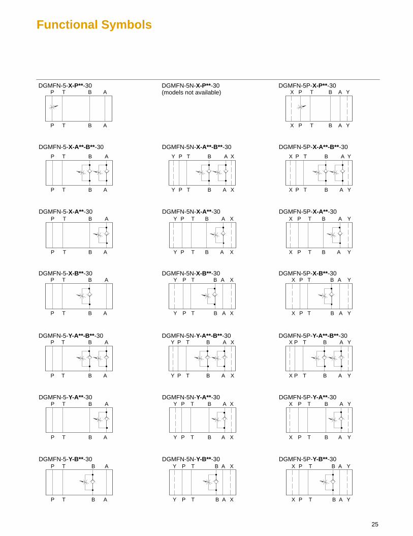
DGMFN Flow Control Valves
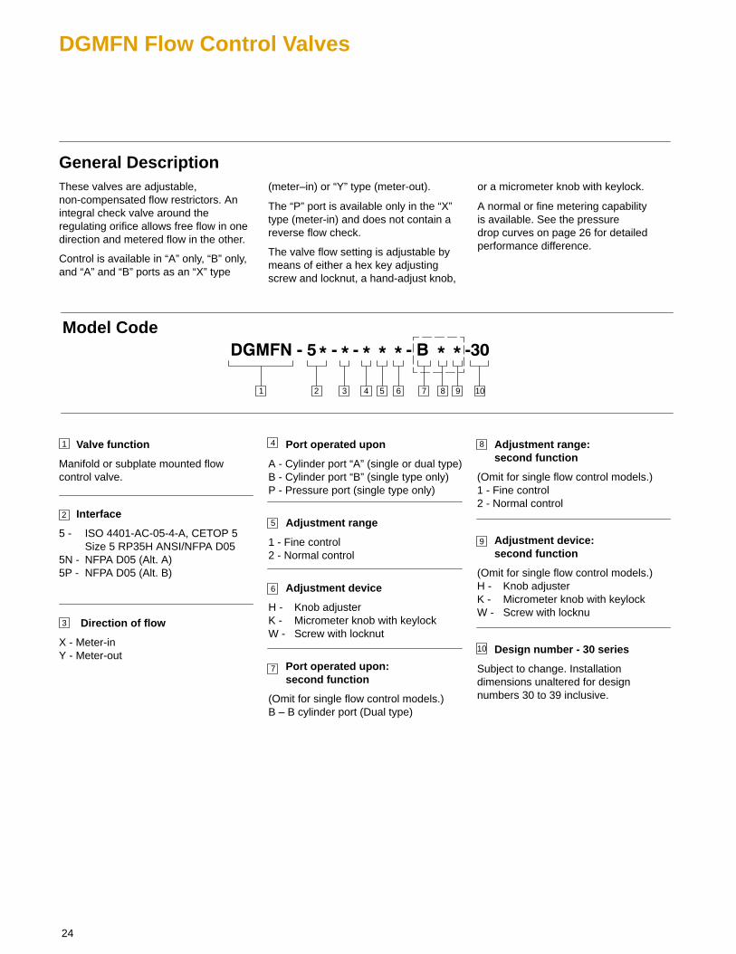
General DescriptionThese valves are adjustable,non-compensated flow restrictors. Anintegral check valve around theregulating orifice allows free flow in onedirection and metered flow in the other.
Control is available in “A” only, “B” only,and “A” and “B” ports as an “X” type
(meter–in) or “Y” type (meter-out).
The “P” port is available only in the “X”type (meter-in) and does not contain areverse flow check.
The valve flow setting is adjustable bymeans of either a hex key adjustingscrew and locknut, a hand-adjust knob,
or a micrometer knob with keylock.
A normal or fine metering capability is available. See the pressure drop curves on page 26 for detailedperformance difference.
3 4 5 10871 2
Model Code
1
2
Valve function
Manifold or subplate mounted flowcontrol valve.
Interface
5 - ISO 4401-AC-05-4-A, CETOP 5 Size 5 RP35H ANSI/NFPA D05
5N - NFPA D05 (Alt. A)5P - NFPA D05 (Alt. B)
Direction of flow
X - Meter-inY - Meter-out
3
4 Port operated upon
A - Cylinder port “A” (single or dual type)B - Cylinder port “B” (single type only)P - Pressure port (single type only)
Adjustment range
1 - Fine control2 - Normal control
Adjustment device
H - Knob adjusterK - Micrometer knob with keylockW - Screw with locknut
Port operated upon: second function
(Omit for single flow control models.)B – B cylinder port (Dual type)
Adjustment range: second function
(Omit for single flow control models.)1 - Fine control2 - Normal control
Adjustment device:second function
(Omit for single flow control models.)H - Knob adjusterK - Micrometer knob with keylockW - Screw with locknu
Design number - 30 series
Subject to change. Installationdimensions unaltered for designnumbers 30 to 39 inclusive.
9
8
10
6 9
5
6
7
25
Functional Symbols
A
P
P
TDGMFN-5-X-P**-30
B
AB
T
A
P
P
TDGMFN-5-Y-A**-B**-30
B
AB
T
A
P
P
TDGMFN-5-Y-A**-30
B
AB
T
A
P
P
TDGMFN-5-X-B**-30
B
AB
T
A
P
P
T
DGMFN-5-X-A**-B**-30
B
AB
T
A
P
P
TDGMFN-5-X-A**-30
B
AB
T
A
P
P
TDGMFN-5-Y-B**-30
B
AB
T
A
P
P
TDGMFN-5P-X-P**-30
B
AB
T
A
P
P
TDGMFN-5P-Y-A**-B**-30
B
AB
T
A
P
P
TDGMFN-5P-Y-A**-30
B
AB
T
A
P
P
TDGMFN-5P-X-B**-30
B
AB
T
A
P
P
T
DGMFN-5P-X-A**-B**-30
B
AB
T
A
P
P
TDGMFN-5P-X-A**-30
B
AB
T
A
P
P
TDGMFN-5P-Y-B**-30
B
AB
T
X
X
Y
Y
X
X
Y
Y
X
X
Y
Y
X
X
Y
Y
X
X
Y
Y
X
X
Y
Y
X
X
Y
Y
A
P
P
TDGMFN-5N-Y-A**-B**-30
B
AB
T
A
P
P
TDGMFN-5N-Y-A**-30
B
AB
T
A
P
P
TDGMFN-5N-X-B**-30
B
AB
T
A
P
P
T
DGMFN-5N-X-A**-B**-30
B
AB
T
A
P
P
TDGMFN-5N-X-A**-30
B
AB
T
A
P
P
TDGMFN-5N-Y-B**-30
B
AB
T
X
X
Y
Y
X
X
Y
Y
X
X
Y
Y
X
X
Y
Y
X
X
Y
Y
X
X
Y
Y
DGMFN-5N-X-P**-30(models not available)
26
Operating Data
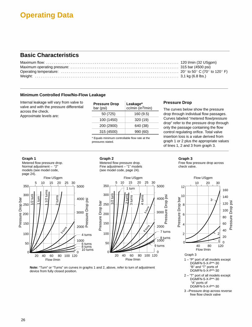
Basic CharacteristicsMaximum flow: 120 l/min (32 USgpm). . . . . . . . . . . . . . . . . . . . . . . . . . . . . . . . . . . . . . . . . . . . . . . . . . . . . . . . . . . . . . . . . . . . . . . Maximum operating pressure: 315 bar (4500 psi). . . . . . . . . . . . . . . . . . . . . . . . . . . . . . . . . . . . . . . . . . . . . . . . . . . . . . . . . . Operating temperature: 20� to 50� C (70� to 120� F). . . . . . . . . . . . . . . . . . . . . . . . . . . . . . . . . . . . . . . . . . . . . . . . . . . . . . . . . . . . . . . Weight: 3,1 kg (6.8 lbs.). . . . . . . . . . . . . . . . . . . . . . . . . . . . . . . . . . . . . . . . . . . . . . . . . . . . . . . . . . . . . . . . . . . . . . . . . . . . .
Minimum Controlled Flow/No-Flow Leakage
Internal leakage will vary from valve tovalve and with the pressure differentialacross the check. Approximate levels are:
Pressure Dropbar (psi)
Leakage*cc/min (in3/min)
50 (725) 160 (9.5)
100 (1450) 320 (19)
200 (2900) 640 (38)
315 (4500) 990 (60)
* Equals minimum controllable flow rate at thepressures stated.
Pressure Drop
The curves below show the pressuredrop through individual flow passages.Curves labeled “metered flow/pressuredrop” refer to the pressure drop throughonly the passage containing the flowcontrol regulating orifice. Total valveinsertion loss is a value derived fromgraph 1 or 2 plus the appropriate valuesof lines 1, 2 and 3 from graph 3.
Graph 1
Pre
ssur
e D
rop
bar
Pre
ssur
e D
rop
psi
150
100
1000
0 0
Flow l/min
Flow USgpm
20 40 60 80 100 120
5 10 15 20 25 30
50
300
250
2000
4000
5000350
Graph 2 Graph 3
200 3000
Metered flow pressure drop.Normal adjustment – “2”models (see model code, page 24).
10 turns8 turns6 turns
1 tu
rn
1 1/
2 tu
rns
2 tu
rns
4 turns
150
100
1000
0 0
Flow l/min
Flow USgpm
20 40 60 80 100 120
5 10 15 20 25 30
50
300
250
2000
4000
5000350
200 3000
Metered flow pressure drop.Fine adjustment – “1” models(see model code, page 24).
1/2
turn
2 tu
rns
3 tu
rns
4 tu
rns
8 turns
7 turns
1 turn
6
4
40
0 0
Flow l/min
Flow USgpm
40 80 120
10 20
220
12
8
60
80
100
120
160
Free flow pressure drop acrosscheck valve.
10 140
30
1
2
3
9 turns
Graph 3
1 – “P” port of all models exceptDGMFN-5-X-P**-30“B” and “T” ports ofDGMFN-5-X-P**-30
2 – “T” port of all models exceptDGMFN-5-X-P**-30 “A” ports ofDGMFN-5-X-P**-30
3 –Pressure drop across reversefree flow check valve
1/2
turn
Pre
ssur
e D
rop
bar
Pre
ssur
e D
rop
psi
Pre
ssur
e D
rop
bar
Pre
ssur
e D
rop
psi
Note: “Turn” or “Turns” on curves in graphs 1 and 2, above, refer to turn of adjustment device from fully closed position.

27
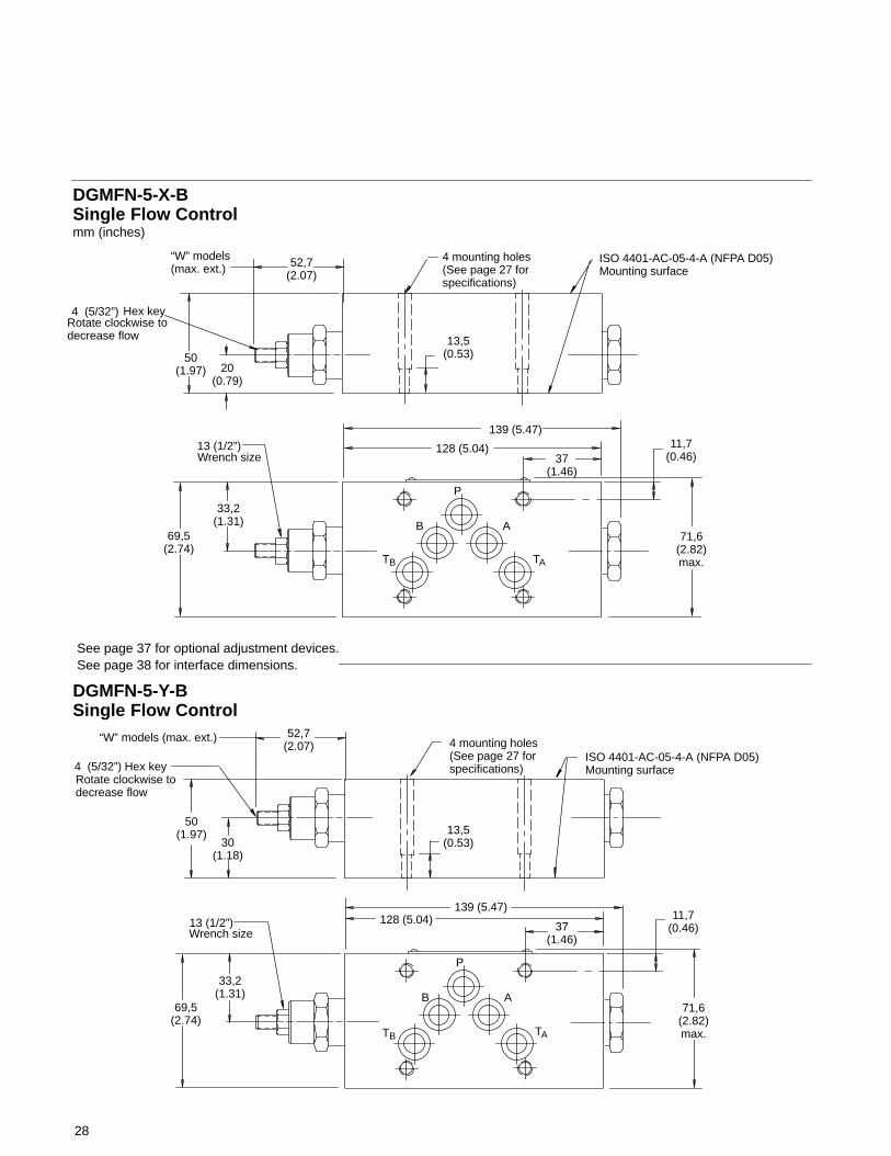
Installation Dimensions
4 mounting holes ∅ 6,9 (0.27) through ∅ 9,50 (0.37) counterbore 36,5 (1.44) deep for bolt extenders (order separately)BKE-6M-50M (M6 metric) orBKE-4-50M (.2500-20 UNC). Torque: 11,3-14,7 Nm (100-130 lb. in.)
ISO 4401-AC-05-4-A(NFPA D05)Mounting surface
DGMFN-5-X-P & DGMFN-5-Y-ASingle Flow Controls
50(1.97)
A“W” models (max. ext.)
13,5(0.53)
128 (5.04)37
(1.46)
11,7(0.46)
B
71,6(2.82)max.
B
P
A
TB
Wrench size
69,5(2.74)
Hex key
Rotate clockwiseto decrease flow
mm (inches)
30(1.18)
139 (5.47)
Model A BDGMFN-5-X-P 60,4 (2.38) 28,4 (1.12)DGMFN-5-Y-A 52,7 (2.07) 33,2 (1.31)
No hex plug onDGMFN-5-X-Pmodels
3rd angleprojection
13 (1/2”)
4 (5/32”)
DGMFN-5-X-ASingle Flow Control
50(1.97)
52,7(2.07)
“W” models (max. ext.)
ISO 4401-AC-05-4-A(NFPA D05)Mounting surface
13,5(0.53)
128 (5.04)
37(1.46)
11,7(0.46)
33,2(1.31)
71,6(2.82)max.
B
P
A
Wrench size
69,5(2.74)
Hex key
Rotate clockwiseto decrease flow
mm (inches)
20(0.79)
4 mounting holes(See above forspecifications)
139 (5.47)
13 (1/2”)
4 (5/32”)
TA
TB TA
See page 38 for interface dimensions.See page 37 for optional adjustment devices.
28
Hex keyRotate clockwise to decrease flow
DGMFN-5-X-BSingle Flow Control
50(1.97)
52,7(2.07)
“W” models (max. ext.)
ISO 4401-AC-05-4-A (NFPA D05)Mounting surface
13,5(0.53)
128 (5.04)37
(1.46)
11,7(0.46)
33,2(1.31)
71,6(2.82)max.
B
P
A
Wrench size
69,5(2.74)
mm (inches)
20(0.79)
139 (5.47)
DGMFN-5-Y-BSingle Flow Control
50(1.97)
52,7(2.07)
“W” models (max. ext.)
13,5(0.53)
128 (5.04)37
(1.46)
11,7(0.46)
33,2(1.31)
71,6(2.82)max.
B
P
A
Wrench size
69,5(2.74)
Hex key
30(1.18)
139 (5.47)
Rotate clockwise to decrease flow
4 mounting holes(See page 27 forspecifications)
4 mounting holes(See page 27 forspecifications)
13 (1/2”)
4 (5/32”)
4 (5/32”)
13 (1/2”)
ISO 4401-AC-05-4-A (NFPA D05)Mounting surface
TB TA
TB TA
See page 38 for interface dimensions.See page 37 for optional adjustment devices.
29
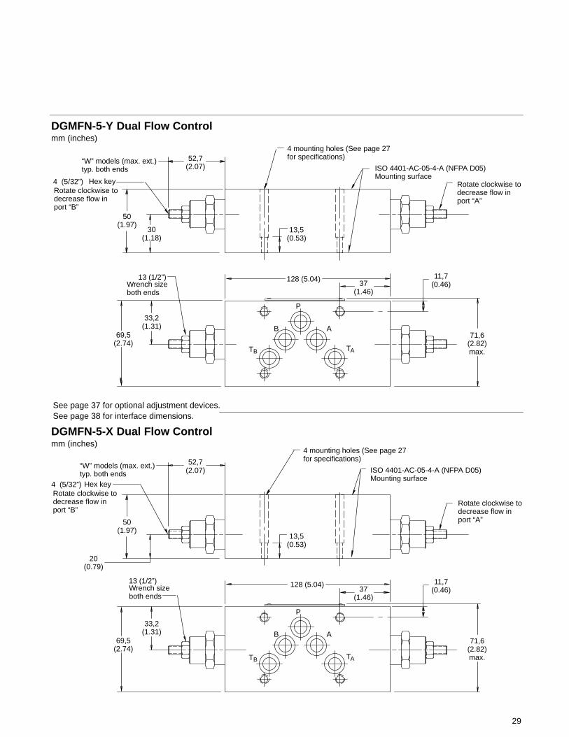
Hex key
DGMFN-5-Y Dual Flow Controlmm (inches)
50(1.97)
52,7(2.07)
“W” models (max. ext.) typ. both ends
13,5(0.53)
128 (5.04)37
(1.46)
11,7(0.46)
33,2(1.31)
71,6(2.82)max.
B
P
A
Wrench sizeboth ends
69,5(2.74)
Hex key
30(1.18)
ISO 4401-AC-05-4-A (NFPA D05)Mounting surface
Rotate clockwise to decrease flow inport “B”
Rotate clockwise to decrease flow inport “A”
DGMFN-5-X Dual Flow Controlmm (inches)
50(1.97)
52,7(2.07)
“W” models (max. ext.)typ. both ends
128 (5.04)37
(1.46)
11,7(0.46)
33,2(1.31)
71,6(2.82)max.
B
P
A
Wrench sizeboth ends
69,5(2.74)
20(0.79)
ISO 4401-AC-05-4-A (NFPA D05)Mounting surface
Rotate clockwise to decrease flow inport “B”
Rotate clockwise to decrease flow inport “A”
4 mounting holes (See page 27for specifications)
4 mounting holes (See page 27for specifications)
13 (1/2”)
4 (5/32”)
13,5(0.53)
13 (1/2”)
4 (5/32”)
TB TA
TB TA
See page 38 for interface dimensions.See page 37 for optional adjustment devices.
30
DGMPC Pilot Operated Check Valves
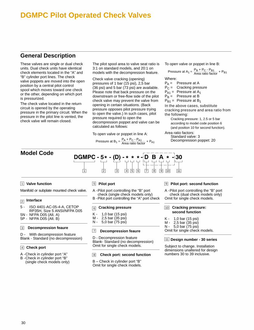
General DescriptionThese valves are single or dual checkunits. Dual check units have identicalcheck elements located in the “A” and“B” cylinder port lines. The check valve poppets are moved into the openposition by a central pilot control spool which moves toward one check or the other, depending on which port is pressurized.The check valve located in the returncircuit is opened by the operatingpressure in the primary circuit. When thepressure in the pilot line is vented, thecheck valve will remain closed.
The pilot spool area to valve seat ratio is3:1 on standard models, and 20:1 onmodels with the decompression feature.
Check valve cracking (opening)pressures of 1 bar (15 psi), 2,5 bar(36 psi) and 5 bar (73 psi) are available.Please note that back pressure on thedownstream or free-flow side of the pilotcheck valve may prevent the valve fromopening in certain situations. (Backpressure opposes pilot pressure tryingto open the valve.) In such cases, pilotpressure required to open thedecompression poppet and valve can becalculated as follows:
To open valve or poppet in line A:
Pressure at B1 =PA + PC - PA1 Area ratio factor
+ PA1
To open valve or poppet in line B:
Pressure at A1 =PB + PC - PB1 Area ratio factor
+ PB1
Where:PA = Pressure at APC = Cracking pressurePA1 = Pressure at A1PB = Pressure at BPB1 = Pressure at B1
In the above cases, substitutecracking pressure and area ratio fromthe following:
Cracking pressure: 1, 2.5 or 5 baraccording to model code position 6(and position 10 for second function).
Area ratio factors:Standard valve: 3Decompression poppet: 20
3 4 71 2
Model Code
1
2
Valve function
Manifold or subplate mounted check valve.
Interface
5 - ISO 4401-AC-05-4-A, CETOP RP35H, Size 5 ANSI/NFPA D05
5N - NFPA D05 (Alt. A)5P - NFPA D05 (Alt. B)
Decompression feaure
D - With decompression featureBlank - Standard (no decompression)
Check port
A -Check in cylinder port “A”B -Check in cylinder port “B”
(single check models only)
3
5
6
Pilot port
A -Pilot port controlling the “B” portcheck (single check models only)
B -Pilot port controlling the “A” port check
Cracking pressure
K - 1,0 bar (15 psi)M - 2,5 bar (35 psi)N - 5,0 bar (75 psi)
Decompression feaure
D - Decompression featureBlank- Standard (no decompression)Omit for single check models.
Check port: second function
B – Check in cylinder port “B”Omit for single check models.
Pilot port: second function
A -Pilot port controlling the “B” portcheck (dual check models only)
Omit for single check models.
Cracking pressure: second function
K - 1,0 bar (15 psi)M - 2,5 bar (35 psi)N - 5,0 bar (75 psi)Omit for single check models.
Design number - 30 series
Subject to change. Installationdimensions unaltered for designnumbers 30 to 39 inclusive.
9
5 6 8 9 10 11
4
7
8
10
11

31
Operating Data
A
P
P
TDGMPC-5-BA*-30
B
A1B1
T
A
P
P
TDGMPC-5-AB*-30
B
A1B1
T
A
P
P
TDGMPC-5-AB*-BA*-30
B
A1B1
T
A
P
P
TDGMPC-5N-BA*-30
B
A1B1
T
A
P
P
TDGMPC-5N-AB*-30
B
A1B1
T
A
P
P
TDGMPC-5N-AB*-BA*-30
B
A1B1
T
Y
Y
X
X
Y
Y
X
X
Y
Y
X
X
A
P
P
TDGMPC-5P-BA*-30
B
A1B1
T
A
P
P
TDGMPC-5P-AB*-30
B
A1B1
T
A
P
P
TDGMPC-5P-AB*-BA*-30
B
A1B1
T
Y
Y
X
X
Y
Y
X
X
Y
Y
X
X
Functional Symbols
Basic CharacteristicsMaximum flow rate: 120 l/min (32 USgpm). . . . . . . . . . . . . . . . . . . . . . . . . . . . . . . . . . . . . . . . . . . . . Maximum operating pressure: 315 bar (4500 psi). . . . . . . . . . . . . . . . . . . . . . . . . . . . . . . . . . . . Leakage @ 50� C (120� F)
Poppet @ 35 bar (500 psi)Standard models 0.3 ml/min.. . . . . . . . . . . . . . . . . . . . . . . . . . . . . . . . . . . . . . . . . “D” models 1.0 ml/min.. . . . . . . . . . . . . . . . . . . . . . . . . . . . . . . . . . . . . . . . . . . . . .
Piston @315 bar (4500 psi) 200 ml/min.. . . . . . . . . . . . . . . . . . . . . . . . . . . . . . . . . . . Operating Temperature: 20� C to 50� C (70� to 120� F). . . . . . . . . . . . . . . . . . . . . . . . . . . . . . . . . . . . . . . . . Weight: 2,9 kg (6.4 lbs). . . . . . . . . . . . . . . . . . . . . . . . . . . . . . . . . . . . . . . . . . . . . . . . . . . . . . .
M
K
N
DGMPC Pressure Drop
Pre
ssur
e dr
op b
ar
Pre
ssur
e dr
op p
si
6
4
0 0
Flow l/min
Flow USgpm
20 40 60 80 100 120
5 10 15 20 25 30
2
8
The curves below show pressure dropthrough each functional flow path in the valve.
10
Model Type
Curve Number
DGMPC-5-(D)-AB*-30
P T A B
DGMPC-5-(D)-BA*-30
DGMPC-5-(D)-AB*-(D)-BA*-30
1
1
1
2
2
2
–
�3�4
–
5
–
5
�
–
�
�3�4
–
– 5
5
�
– –
�
16
14
12
18
20
22
24
50
100
150
200
250
300
1
2
3
4
5
The total insertion loss for the valve mustbe calculated by summing the lossesthrough the four applicable flow paths.
� Flow toward actuator without ckeck – single check only
� Flow from actuator without check – single check only� Use K, M, or N cracking pressure curve as applicable.

32
Installation Dimensions
30(1.18)
50(1.97)
9,9(0.39)
ISO 4401-AC-05-4-A (NFPA D05)Mounting surface
13,5(0.53)
128 (5.04)
37(1.46)
11,7(0.46)
33,2(1.31)
71,6(2.82)max.
B
P
A
TB69,5
(2.74)
mm (inches)
4 mounting holes ∅ 6,9 (0.27) through ∅ 9,50 (0.37) counterbore 36,5 (1.44) deep for bolt extenders (order separately) BKE-6M-50M (M6 metric) or BKE-4-50M (.2500-20 UNC) Torque: 11,3-14,7 Nm (100-130 lb. in.)
DGMPC-5-30Pilot OperatedCheck Valve
9,9(0.39)
TA
See page 38 for interface dimensions.
33
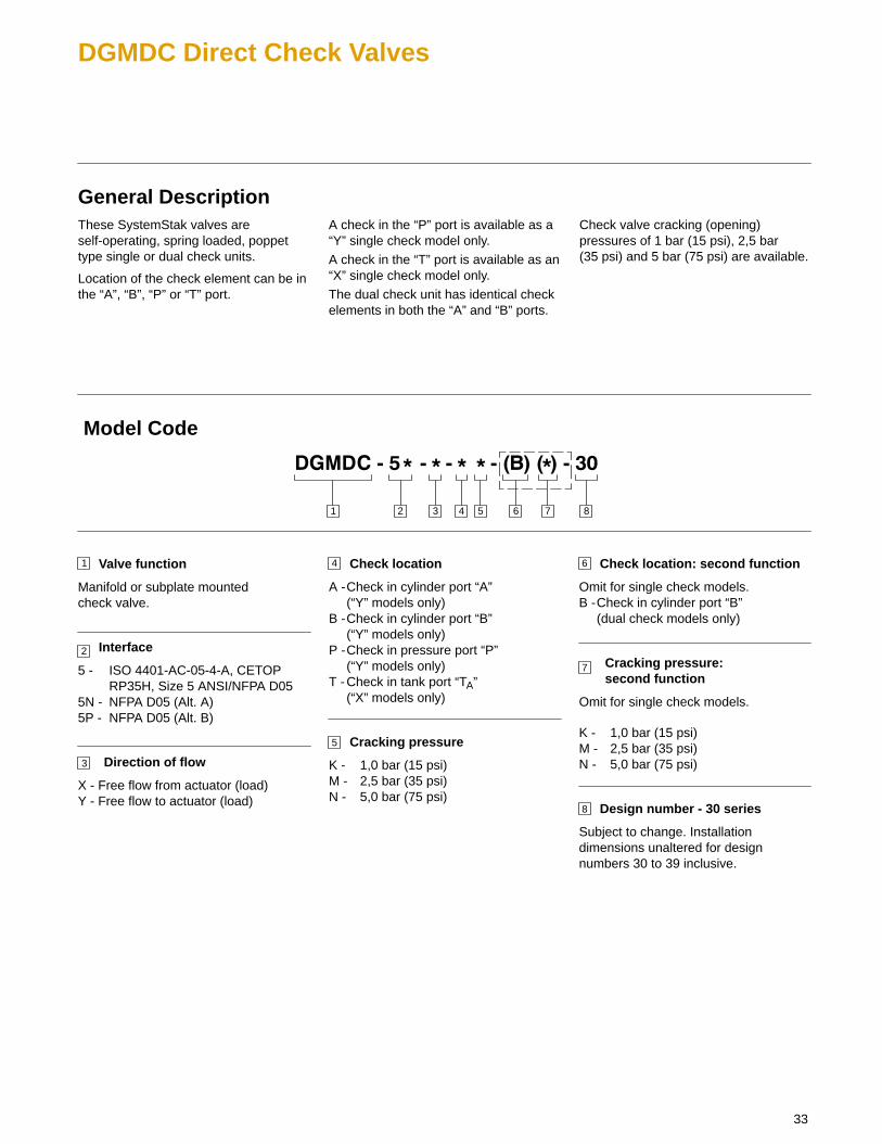
DGMDC Direct Check Valves
General DescriptionThese SystemStak valves areself-operating, spring loaded, poppettype single or dual check units.
Location of the check element can be inthe “A”, “B”, “P” or “T” port.
A check in the “P” port is available as a“Y” single check model only.
A check in the “T” port is available as an“X” single check model only.
The dual check unit has identical checkelements in both the “A” and “B” ports.
Check valve cracking (opening)pressures of 1 bar (15 psi), 2,5 bar(35 psi) and 5 bar (75 psi) are available.
3 4 5 8761 2
1
2
Valve function
Manifold or subplate mountedcheck valve.
Interface
5 - ISO 4401-AC-05-4-A, CETOP RP35H, Size 5 ANSI/NFPA D05
5N - NFPA D05 (Alt. A)5P - NFPA D05 (Alt. B)
Direction of flow
X - Free flow from actuator (load)Y - Free flow to actuator (load)
3
4
5
Check location
A -Check in cylinder port “A” (“Y” models only)
B -Check in cylinder port “B” (“Y” models only)
P -Check in pressure port “P”(“Y” models only)
T -Check in tank port “TA”(“X” models only)
Cracking pressure
K - 1,0 bar (15 psi)M - 2,5 bar (35 psi)N - 5,0 bar (75 psi)
Check location: second function
Omit for single check models.B -Check in cylinder port “B”
(dual check models only)
Cracking pressure: second function
Omit for single check models.
K - 1,0 bar (15 psi)M - 2,5 bar (35 psi)N - 5,0 bar (75 psi)
Design number - 30 series
Subject to change. Installationdimensions unaltered for designnumbers 30 to 39 inclusive.
7
6
8
Model Code

34
Functional Symbols
A
P
P
TB
DGMDC-5-Y-P*-30TA
B
AB
TATB
A
P
P
TB
DGMDC-5-X-T*-30TA
B
AB
TATB
A
P
P
TB
DGMDC-5-Y-A*-30TA
B
AB
TATB
A
P
P
TB
DGMDC-5-Y-B*-30TA
B
AB
TATB
A
P
P
TB
DGMDC-5-Y-A*-B*-30TA
B
AB
TATB
DGMDC-5P-Y-P*-30
DGMDC-5P-X-T*-30
A
P
P
TB
DGMDC-5P-Y-A*-30TA
B
AB
TATB
DGMDC-5P-Y-B*-30
DGMDC-5P-Y-A*-B*-30
X
X
Y
Y
A
P
P
TB TA
B
AB
TATB
X
X
Y
Y
A
P
P
TB TA
B
AB
TATB
Y
Y
X
X
A
P
P
TB TA
B
AB
TATB
Y
Y
X
X
A
P
P
TB TA
B
AB
TATB
Y
Y
X
X
DGMDC-5N-X-T*-30
A
P
P
TB
DGMDC-5N-Y-A*-30TA
B
AB
TATB
DGMDC-5N-Y-B*-30
DGMDC-5N-Y-A*-B*-30
X
X
Y
Y
A
P
P
TB TA
B
AB
TATB
X
X
Y
Y
A
P
P
TB TA
B
AB
TATB
Y
Y
X
X
A
P
P
TB TA
B
AB
TATB
Y
Y
X
X
35
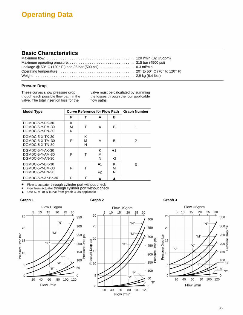
Operating Data
Basic CharacteristicsMaximum flow: 120 l/min (32 USgpm). . . . . . . . . . . . . . . . . . . . . . . . . . . . . . . . . . . . . . . . . . . . . . . . . Maximum operating pressure: 315 bar (4500 psi). . . . . . . . . . . . . . . . . . . . . . . . . . . . . . . . . . . . Leakage @ 50� C (120� F ) and 35 bar (500 psi) 0.3 ml/min.. . . . . . . . . . . . . . . . . . . Operating temperature: 20� to 50� C (70� to 120� F). . . . . . . . . . . . . . . . . . . . . . . . . . . . . . . . . . . . . . . . . Weight: 2,9 kg (6.4 lbs.). . . . . . . . . . . . . . . . . . . . . . . . . . . . . . . . . . . . . . . . . . . . . . . . . . . . . . .
Presure Drop
These curves show pressure dropthough each possible flow path in thevalve. The total insertion loss for the
valve must be calculated by summingthe losses through the four applicableflow paths.
Model Type Curve Reference for Flow Path Graph Numberyp
P T A B
p
DGMDC-5-Y-PK-30DGMDC-5-Y-PM-30DGMDC-5-Y-PN-30
KMN
T A B 1
DGMDC-5-X-TK-30DGMDC-5-X-TM-30DGMDC-5-X-TN-30
PKMN
A B 2
DGMDC-5-Y-AK-30DGMDC-5-Y-AM-30DGMDC-5-Y-AN-30
P TKMN
�1
�2
DGMDC-5-Y-BK-30DGMDC-5-Y-BM-30DGMDC-5-Y-BN-30
P T�1
�2
KMN
3
DGMDC-5-Y-A*-B*-30 P T � �
� Flow to actuator through cylinder port without check� Flow from actuator through cylinder port without check� Use K, M, or N curve from graph 3, as applicable
“N”
“M”
“K”
Pre
ssur
e D
rop
bar
Pre
ssur
e D
rop
psi
15
10
100
0 0
Flow l/min
Flow USgpm
20 40 60 80 100 120
5 10 15 20 25 30
550
25
20
150
200
250
300
350
“T”
“A”
“B”
“N”
“M”
“K”
Graph 1
Pre
ssur
e D
rop
bar
15
10
100
0 0
Flow l/min
Flow USgpm
20 40 60 80 100 120
5 10 15 20 25 30
550
25
20
150
200
250
300
350
“P”“A”
“B”
40030
Graph 2
15
10
100
0 0
Flow l/min
Flow USgpm
20 40 60 80 100 120
5 10 15 20 25 30
550
25
20
150
200
250
300
350
“N”
“M”
“K”
Graph 3
“2”
“P”
“T”“1”P
ress
ure
Dro
p ps
i
Pre
ssur
e D
rop
bar
Pre
ssur
e D
rop
psi

36
Installation Dimensions
50(1.97)
9,9 (0.39) ISO 4401-AC-05-4-A (NFPA D05)Mounting surface
13,5(0.53)
128 (5.04)37
(1.46)
11,7(0.46)
33,2(1.31)
71,6(2.82)max.
B
P
A
TB
69,5(2.76)
mm (inches)
30(1.18)
4 mounting holes ∅ 6,9 (0.27) through ∅ 9,50 (0.37) counterbore 36,5 (1.44) deep for bolt extenders (order separately)BKE-6M-50M (M6 metric) orBKE-4-50M (.2500-20 UNC). Torque: 11,3-14,7 Nm (100-130 lb. in.)
DGMDC-5-Y-A*-B*-30Dual Direct Check Valve
9,9 (0.39)(max.)
50(1.97)
ISO 4401-AC-05-4-A (NFPA D05)Mounting surface
13,5(0.53)
30(1.18)
9,9 (0.39)(max.)
DGMDC-5-X-T*-30Single Direct Check Valve
50(1.97)
ISO 4401-AC-05-4-A(NFPA D05)Mounting surface
13,5(0.53)
17(.669)
9,9 (0.39)(max.)
DGMDC-5-Y-P*-30Single Direct Check Valve
4 mounting holes(See above forspecifications)
4 mounting holes(See above forspecifications)
TA
See page 38 for interface dimensions.

37
Knob Adjusters
DGMCDGMC2 (dual type)DGMR1DGMX2
56,8 (2.24) “H” models (max. ext.)
2 (5/64”)Hex key required for adjustment
82,9 (3.26)“K” models 45(1.77)
For key removal
max. ext.
DGMC2(crossport type)
54,1 (2.13) “H” models (max. ext.)
Hex key required for adjustment
80,1 (3.15)“K” models 45(1.77)
For key removal
max. ext.
DGMFN C “H” models (max. ext.)
Hex keyrequired foradjustment
D“K” models 45(1.77)
For key removal
max. ext.
Adjustment of valve setting is only possible while key is inserted andturned to engage driving pin. When key is removed, adjuster knobcan be freely spun and does not engage with setting mechanism.
Model C D
DGMFN-5-X-P 68,9 (2.37) 95 (3.74)DGMFN-5-Y-A 61,9 (2.44) 88 (3.46)
DGMR
74,4 (2.93)
Hex key required for adjustment
H – Handknob C – Cap over screwW – Screw with locknut
65,6 (2.58) 68,5 (2.70)
13 (1/2”)Wrench size
Hex key4 (5/32)
2 (5/64”)
2 (5/64”)
Adjustment of valve setting is only possible while key is inserted andturned to engage driving pin. When key is removed, adjuster knobcan be freely spun and does not engage with setting mechanism.
Adjustment of valve setting is only possible while key is inserted andturned to engage driving pin. When key is removed, adjuster knobcan be freely spun and does not engage with setting mechanism.
2 (5/64”)
13 (1/2”)Wrench size

38
Mounting Surface
Dimensions mm (inches)
����������
� �!��"��"�
"������������ �����"��
�������#��
"�����"#�
��#����� �
�����������
���#��"���
�� �������
��
�
�
�"������#��
�������� �
�"����"���� #������ "�
�
�
�
����������
$
%
%
DGM**-5N
DGM**-5
������� �
�������� �
������"��#� �����������
�
�
�
DGM**-5P
����������
$
����������
The “5” interface accepts Vickers DG4S4directional valves and other directional valves with a standard ISO 4401-05, NFPA-D05, ANSI/B93.7M size D05 or CETOP-5 port pattern.
The “5N” NFPA-D05 interface accepts Vickers DG3S-5, DG5S-5, DG5V-5 and DG18S4-01 directional valves.
The “5P” NFPA-D05interface acceptsVickers DG5S4-02directional valves.
��
�� ��
�� ��

39
Bolt Extender Kits
ISO 4401-05 SystemStak valves may bemounted with either standard capscrews or bolt extender kits.
Metric cap screws must be of Class 12,9(ISO 898) strength, minimum U.T.S. =1200 MPa.
Inch threaded screws must conform toANSI B18.3.
The use of Vickers bolt extenderssimplifies installation by permitting eachvalve body to be separately installedwith the correct torque value. A major
advantage of bolt extenders is the abilityto remove the directional valve forservice or replacement withoutdisturbing the stack assembly. There are4 bolt extenders per kit.
SystemStakV lve Height
Metric InchExtender Torq eValve Height
mm (inch) Thread Kit Model Number Thread Kit Model NumberExtender Torque
50 (1.97) M6 x 1-6H BKE-6M-50M .2500-20 UNC BKE-4-50M11 3 14 7 Nm (100 130 lbf in)
60 (2.36) M6 x 1-6H BKE-6M-60M .2500-20 UNC BKE-4-60M11,3-14,7 Nm (100-130 lbf in)
DirectionalValve
ÉÉÉÉÉÉÉÉÉÉÉÉÉÉÉÉÉÉÉÉÉÉÉÉÉÉÉÉÉÉÉÉÉÉÉÉÉÉÉÉÉÉÉÉÉÉÉÉÉÉÉÉÉÉÉÉÉÉÉÉÉÉÉÇÇÇÇÇÇÇÇÇÇÇÇÇÇÇÇÇÇÇÇÇÇÇÇÇÇÇÇÇÇÇÇÇÇÇÇÇÇÇÇÇÇÇÇÇÇÇÇÇÇÇÇÇÇÇÇÉÉÉÉÉÉÉÉÉÉÉÉÉÉÉÉÉÉÉÉÉÉÉÉÉÉÉÉÉÉÉÉÉÉÉÉÉÉÉÉÉÉÉÉÉÉÉÉÉ
60(2.36)
SystemStak Valve
50(1.97)
SystemStak Valve
Manifold Block
M6 x 1 or.2500-20 thread
Bolt Extender
4,0 (5/32”) hexsocket fortightening Standard
socket headcap screw
Bolt extender kit BKE-6M-60M orBKE-4-60M
Bolt extender kit BKE-6M-50M orBKE-4-50M
12 (0.47) minimum thread engagement
4 (5/32”)hexsocket
4 (5/32”)hexsocket
Example of bolt extenders on a typical SystemStak assemblyBolt extender cross section
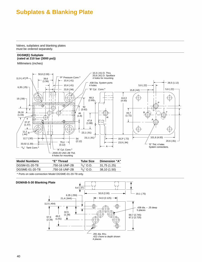
40
Subplates & Blanking Plate
Valves, subplates and blanking platesmust be ordered separately.
“TA” Tank Conn.*
39,6(1.56)
50,8 (2.00)
Millimeters (inches)
B T
P
A
B
10,4 (.41)
10,4 (.41)
23,9 (.94)
92(3.62)
46(1.8)
23,1 (.91)
47,8(1.88)
23,1 (.91)
68,3(2.69)
18,3* (.72)
23,9 (.94)
A
101,6 (4.00)
114,3(4.50)
43,7(1.72)
20,6 (.81)
5,6 (.22)15,8 (.62)
5,6 (.22)28,5 (1.12)
79,4(3.12)33,02 (1.30)
12,7 (.50) 54 (2.12)
37,3*(1.47)
26,16(1.03)
15 (.59)
6,35 (.25)
11,2(.44)
R
11,9 (.47) R “P” Pressure Conn.*
10,3 (.41) D. Thru 20,6 (.81) D. Spotface 4 holes for mounting
.438 Dia. System ports4 holes
.2500-20 UNC-2B Thd. 4-holes for mounting
* Ports on side-connection Model DGSME-01-20-T8 only.
“E” Thd. 4 holes System connections.
Model Numbers “E” Thread Tube Size Dimension “A”DGSM-01-20-T8 .750-16 UNF-2B 1/2” O.D. 31,75 (1.25)DGSME-01-20-T8 .750-16 UNF-2B 1/2” O.D. 38,10 (1.50)
“A” Cyl. Conn.*
“B” Cyl. Conn.*
DGSM(E) Subplate(rated at 210 bar (3000 psi))
50,8 (2.00)
57,9(2.28)
DGMAB-5-30 Blanking Plate
54,0 (2.125)
9,4 (.37)
19,1 (.75)
69,7 (2.745)67,2 (2.725)
11,5 (.454)
46,0(1.81)
32,5(1.28)
21,4 (.844)6,35 (.250)
.438 dia. – .25 deep5 places
.281 dia. thru.
.422 c’bore to depth shown4 places
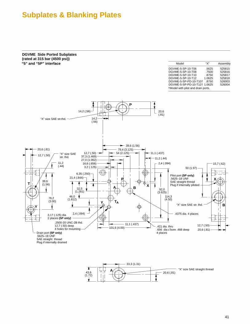
41
Subplates & Blanking Plates
DGVME Side Ported Subplates(rated at 315 bar (4500 psi))
79,4 (3.125)54 (2.125)
3,2 (.125)16,6 (.656)
27,0 (1.062)37,3 (1.469)
101,6 (4.00)
Model Assembly
DGVME-5-SP-10-T06 .5625 525815DGVME-5-SP-10-T08 .7500 525816DGVME-5-SP-10-T10 .8750 525817DGVME-5-SP-10-T12 1.0625 525818DGVME-5-SP-PD-10-T10† .8750 526003DGVME-5-SP-PD-10-T12† 1.0625 526004
“X” size SAE straight thread
“X”
114,3(4.50)
92,0(3.625)
46,0(1.812)
32,5(1.281)
21,4 (.844)6,35 (.250)
43,6(1.72)
“5” and “5P” interface
.4375 dia. 4 places
Pilot port (5P only).5625–18 UNF SAE straight threadPlug if internally piloted
“X” size SAE str. thd.
“X” size SAE str. thd.
“X” size SAE str.thd.
A
X
P
B
T
Y
Drain port (5P only).5625–18 UNF SAE straight threadPlug if internally drained
.421 dia. thru
.656 dia c’bore .468 deep 4 places
†Model with pilot and drain ports.
3,17 (.125) dia. 2 places (5P only)
TA
A
P
B X
Y
20,6 (.81)
33,3 (1.31)
15,7 (.62)
50 (1.97)
20,6 (.81)
12,7 (.50)
12,7 (.50)
20,6 (.81)
39,6 (1.56)
76,2 (3.00)
14,2 (.56) 20,6 (.81)
14,2 (.56)
39,6 (1.56)
2,4 (.094)
2,4 (.094)
11,1 (.437)
11,2 (.44)
11,1 (.437)
12,7 (.50)
.2500-20 UNC-2B thd.12,7 (.50) deep 4 holes for mounting
11,2 (.44)

42
Subplates & Blanking Plates
DGVM Bottom Ported Subplates(rated at 315 bar (4500 psi))
79,4 (3.125)
54 (2.125)
3,2 (.125)
12,7 (.50)
16,6 (.656)27,0 (1.062)37,3 (1.469)
101,6 (4.00)
.421 dia. thru
.656 dia c’bore .468 deep 4 places
3,17 (.125) dia. 2 places(5P only)
Model Assembly
DGVM-5-SP-10-T06 .5625 525811DGVM-5-SP-10-T08 .7500 525812DGVM-5-SP-10-T10 .8750 525813DGVM-5-SP-10-T12 1.0625 525814DGVM-5-SP-PD-10-T10† .8750 525832DGVM-5-SP-PD-10-T12† 1.0625 525833
“X”
114,3(4.50)
92,0(3.625)
46,0(1.812)
32,5(1.281)
21,4 (.844)6,35 (.250)
“5” and “5P” interface
.4375 dia.4 places
P
A
BT
Y
XP
B
TA
A
X
Y
69,8 (2.75)(39,6 (1.56)
33,3 (1.31)
9,6 (.38)
52,3(2.06)
82,5(3.25)
9,6(.38)
73,0(2.88)
43,6 (1.72)
1,5 (.06)11,2 (.44)
77,7 (3.06)
(39,6 (1.56)
“X” size SAE str. thd.Spotface 2,4 (.094) deep4 places
19 (.75)
Pilot port (5P only).5625–18 SAE str. thd.Plug if internally piloted
Drain port. (5P only) .5625–18 UNF SAE str. thd.Plug if internally drained
†Model with pilot and drain ports.
.2500-20 UNC-2B thd.12,7 (.50) deep 4 holes for mounting
11,2 (.44)
2,4 (.094)
2,4 (.094)
11,1 (.437)
11,1 (.437)
43
Application Data
Fluid CleanlinessProper fluid condition is essential forlong and satisfactory life of hydrauliccomponents and systems. Hydraulicfluid must have the correct balance ofcleanliness, materials, and additives forprotection against wear of components,elevated viscosity, and inclusion of air.
Essential information on the correctmethods for treating hydraulic fluid isincluded in Vickers publication 561“Vickers Guide to SystemicContamination Control” available fromyour local Vickers distributor or by
contacting Vickers, Incorporated.Recommendations on filtration and theselection of products to control fluidcondition are included in 561.
Recommended cleanliness levels,using petroleum oil under commonconditions, are based on the highestfluid pressure levels in the system andare coded in the chart below. Fluidsother than petroleum, severe servicecycles, or temperature extremes arecause for adjustment of thesecleanliness codes. See Vickerspublication 561 for exact details.
Vickers products, as any components,will operate with apparent satisfaction influids with higher cleanliness codes thanthose described. Other manufacturerswill often recommend levels abovethose specified. Experience has shown,however, that life of any hydrauliccomponent is shortened in fluids withhigher cleanliness codes than thoselisted below. These codes have beenproven to provide a long, trouble-freeservice life for the products shown,regardless of the manufacturer.
System Pressure Levelbar (psi)
Product <70 (<1000) 70-207 (1000-3000) 207+ (3000+)
Directional Valves 20/18/15 20/18/15 19/17/14
Pressure/Flow Control Valves 19/17/14 19/17/14 19/17/14
Fluid Viscosity
16-51 cSt (575-250 SUS)
Fluids and Seals
Flurocarbon seals are standard and aresuitable for use with phosphate estertype fluids or their blends, water glycol,water-in-oil emulsion fluids andpetroleum oil.
Form No. 00-000 Copyright Eaton Corporation, 0000All rights reserved.Printed in U.S.A
Eaton Hydraulics15151 Highway 5Eden Prairie, MN 55344Telephone: 612 937-7254Fax: 612 937-7130www.eatonhydraulics.com
46 New Lane, HavantHampshire PO9 2NBEnglandTelephone: (44) 170-548-6451Fax: (44) 170-548-7110