Vickers Cartridge Valves Flow Controls - 4wings4wings.com/lib/files/control_valve.pdf · Vickers®...
78
Rev2/99 723 Screw-in Cartridge Valves Pressures to 350 bar (5000 psi) – Flows to 570 l/min (150 USgpm) Vickers ® Cartridge Valves Flow Controls
Transcript of Vickers Cartridge Valves Flow Controls - 4wings4wings.com/lib/files/control_valve.pdf · Vickers®...

Rev2/99 723
Screw-in Cartridge ValvesPressures to 350 bar (5000 psi) – Flows to 570 l/min (150 USgpm)
Vickers®
Cartridge Valves
Flow Controls

2
Introduction
For over seventy years, Vickers hasprovided its customers with qualityproducts and innovative solutions for alltheir power and motion control needs.The products featured in this catalogrepresent the very best in screw-incartridge flow control technology.
Products in this catalog have beenfatigue tested for one million cycles at132% or 10 million cycles at 115% ofrated pressure.
Two pressure ratings are shown for mostproducts featured in this catalog – typicalapplication pressure and fatigue pressure.The typical application pressure is themaximum recommended operating pressurefor the valve in a given system. The fatiguepressure is the maximum pressure for thevalve to be free, for infinite life, from metalfatigue problems.We are committed to maintaining thisposition by offering the most comprehensiverange of cartridge valves for industrial andmobile equipment.This catalog gives basic specifications forthe complete line of Vickers screw-incartridge flow control valves. Its purpose isto provide a quick, convenient referencetool when choosing Vickers cartridgevalves or designing a system using thesecomponents.
Valve Features and BenefitsVickers offers a complete range of flowcontrols with a variety of features,including:� Non-adjustable, pressure compensated,
flow regulator for flows to 227 l/min (60USgpm).
� Adjustable, pressure compensated, flowregulator for flows to 114 l/min (30USgpm).
� Fixed and adjustable priority bypass typeflow regulator for regulated flows to 114l/min (30 USgpm).
� Adjustable flow control without freereverse flow check with flows rated to114 l/min (30 gpm).
� Adjustable flow control with free reverseflow check with flows rated to 45 l/min(12 gpm).
� Needle valves with flows rated to 265l/min (70 USgpm).
�Vickers, Incorporated 1999All Rights Reserved
� Velocity fuses with flows rated to 227l/min (60 USgpm).
� Flow divider/combiners (FDC1) withflows rated to 568 l/min (150 USgpm).
� Posi-traction valves (FDC3) with flowsrated to 567 l/min (150 USgpm)
� Operating pressures to 350 bar (5000 psi).
Here are some of the benefits of Vickersflow controls:� All operating parts are hardened steel,
ground and honed for long life and lowleakage.
� Designed for maximum flexibility andminimal space requirements.
� All exposed cartridge surfaces are zincdichromate plated to resist corrosion.Steel housings are available forcartridges rated to 350 bar (5000 psi)application pressures.
� All aluminum manifolds are goldanodized to resist corrosion.
� Reliable, economical and compact.� Low leakage.� Variety of adjustment options.� Adjustments designed not to go spring
solid at “full in” position or to allow theadjustment to be removed when backedout.
Notable are the two styles of flowdivider/combiner:
FDC1-**The FDC1-** is a cartridge type hydraulicflow divider-combiner valve. It divides andcombines flow, regardless of system loador pressure, proportionally per specifiedflow division.For example: FDC1-10-*–66 will divide anincoming flow of 45 l/min (12 USgpm) equally out each port with anaccuracy of �10% each side. With 45l/min (12 USgpm) in at “3” port, flow outport “4” can be 22 l/min(6 USgpm) � 4,5 l/min (1.2 USgpm) whileflow at port “2” is 22,7 l/min(6 USgpm) �4,5 l/min (1.2 USgpm).The combining accuracy is the same withincoming flow at port “4” and “2” and flowout port “3” of 45 l/min(12 USgpm). Inlet flow at port “4” will be 22l/min (6 USgpm) �4,5 l/min(1.2 USgpm). Inlet flow at port “2” will be22 l/min (6 USgpm) � 4,5 l/min(1.2 USgpm).
Flow division or combining will bemaintained even if unequal loads areplaced on ports “4” and “2”.
A special feature of the FDC1–* is that itprovides rephase flow to either port 2 or port4 when one of the two is blocked. Thisfeature is useful in hydraulic circuits thatrequire cylinders to move at the same time. Ifone cylinder bottoms out first, the oppositecylinder is provided with “rephase” flow toallow the cylinder to bottom and start thecylinders together for movement in theopposite direction.
FDC3-**The FDC3-** is a cartridge type positivetraction valve that divides and combinesflow, regardless of system load orpressure, proportionally per specified flowdivision.
This valve is used in place of a standard flowdivider-combiner in systems where hydraulicmotors are used as drive wheels on eachside of the machine. The positive tractionvalve acts much like a standard flowdivider-combiner as the vehicle travels in astraight line. Equal amounts of flow go toeach “C” port. As the vehicle turns a corner,a standard flow divider will maintain equalflow to each drive motor. On a turn, it isnecessary for the outer wheel to turn fasterthan the inner wheel. A standard flowdivider-combiner will provide equal flow toeach motor causing the drive motors to skid.The positive traction valve solves thisproblem by allowing the one motor to turnfaster than the other.This operates in a similar way as amechanical differential on an automobile.In a turn, the inside drive motor is restrictedand builds up pressure, while the outsidedrive motor is without restriction. Underconditions of high differential pressure, thepositive traction valve passes extra flow tothe least restricted motor to preventskidding. Under straight running conditionsthe differential pressure is low and equalamounts of flow are provided to each drivemotor.
WARNING: Forpressure over 210 bar(3000 psi) use steelhousing.

3
Contents
MODEL DESCRIPTION TYPICALAPPLICATIONPRESSURE
bar (psi)
RATED FLOWl/min (USgpm)
PAGE
Introduction 2FR5-8 350 (5000) 10 (2.5) 4
FR5-10 350 (5000) 23 (6) 6
FR1-16Flow reg l tor v lves fixed press re compens ted
210 (3000) 114 (30) 8
FR1-20Flow regulator valves, fixed, pressure compensated
210 (3000) 227 (60) 10
FR2-10 210 (3000) 38 (10) 12
FR2-16 210 (3000) 114 (30) 14
FAR1-10 350 (5000) 38 (10) 16
FAR1-12 Flow regulator valves, adjustable, pressure compensated 350 (5000) 94,5 (25) 18
FAR1-16g , j ,
350 (5000) 3,8–113,6 (1–30) 20
PFR5-8 350 (5000) 15,1 (4) 22
PFR5-10 350 (5000) 60 (15) 24
PFR1-16 Priority flow regulator valves 210 (3000) 151 (40) 26
PFR2-10y g
210 (3000) 60 (15) 28
PFR2-16 210 (3000) 151 (40) 30
MRV2-10M n l rot ry v lves
210 (3000) 18,9–56,7 (5–15) 32
MRV2-16Manual rotary valves
210 (3000) 37,8–170,3 (10–45) 34
NV1-8 350 (5000) 45 (12) 36
NV1-10Needle v lves
210 (3000) 45 (12) 38
NV1-16Needle valves
210 (3000) 151 (40) 40
NV1-20 210 (3000) 265 (70) 42
FCV7-10 210 (3000) 45 (12) 44
FCV11-12 Flow control valves 350 (5000) 114 (30) 46
FCV6-16 210 (3000) 208 (55) 48
VF1-10 210 (3000) 23 (6) 50
VF1-16 Velocity fuse 210 (3000) 114 (30) 52
VF1-20y
210 (3000) 227 (60) 54
FDC1-10 210 (3000) 5,7–60,8 (1.5–16) 56
FDC1-16 Flow divider/combiner 210 (3000) 45,6–178 (12–47) 58
FDC1-20 210 (3000) 190–380 (50–100) 60
FDC3-10 210 (3000) 22,8–60,8 (6–16) 62
FDC3-16 Posi-traction valves 210 (3000) 60–228 (15–60) 64
FDC3-20 210 (3000) 190–570 (50–150) 66
C-**-2 Cavity Dimensions 68C-**-3 Cavity Dimensions 69C-**-4 Cavity Dimensions 70C-**-2 Aluminum Housings 71C-**-3 Aluminum Housings 72C-**-4 Aluminum Housings 73C-**-2 Steel Housings 74C-**-3 Steel Housings 75SupportingProducts
Roughing toolsFinishing tools
7676
Index 77

4
FR5-8 Flow regulator, fixed
0
Sectional View
DescriptionThe FR5–8 is a fixed orifice, pressure compensated, restrictive flow regulatorscrew-in cartridge valve.
OperationThis valve maintains a constant flow from port 1 to port 2 based on 5.5 bar(80 psid) regardless of pressure changes downstream on port 2. Reverse flowfrom port 2 to port 1 is at the value of the fixed orifice and is non-pressurecompensated.
Ratings and specificationsPerformance data is typical with fluid at 21,8 cSt (105 SUS) and 49�C (120�F)Typical application pressure (all ports) 350 bar (5000 psi) steel housing. . . . . . . . . . .
210 bar (3000 psi) aluminum housingCartridge fatigue pressure (infinite life) 280 bar (4000 psi). . . . . . . . . . . . . . . . . . . . . . . Rated flow 10 l/min (2.5 USgpm). . . . . . . . . . . . . . . . . . . . . . . . . . . . . . . . . . . . . . . . . . . .
Flow regulation 0,4–1,9 l/min (0.1–0.49 USgpm) �20% @ 210 bar (3000 psi). . . . . . accuracy 0,4–1,9 l/min (0.1–0.49 USgpm) �40% @ 350 bar (5000 psi)
1,9 – 5,7 l/min (0.5–1.49 USgpm) �15% 5,7–10 l/min (1.5–2.5 USgpm) �10%
Factory set maximum flow rate accuracy under standard test conditions and within the above ranges
Temperature range –40 to 120�C (–40� to 248�F). . . . . . . . . . . . . . . . . . . . . . . . . . . .
Cavity C–8–2 (See page 68). . . . . . . . . . . . . . . . . . . . . . . . . . . . . . . . . . . . . . . . . . . . . . . .
Fluids All general purpose hydraulic fluids such as:. . . . . . . . . . . . . . . . . . . . . . . . . . . . . MIL–H–5606, SAE 10, SAE 20, etc.
Filtration Cleanliness code 18/16/13. . . . . . . . . . . . . . . . . . . . . . . . . . . . . . . . . . . . . . . . . .
Standard housing materials Aluminum or steel. . . . . . . . . . . . . . . . . . . . . . . . . . . . . . . . . Weight cartridge only 0,05 kg (0.12 lbs.). . . . . . . . . . . . . . . . . . . . . . . . . . . . . . . . . . . . . . .
Seal kits 02–165875 Buna-N. . . . . . . . . . . . . . . . . . . . . . . . . . . . . . . . . . . . . . . . . . . . . . . . 02–165877 Viton
Viton is a registered trademark of E.I. DuPont
Typical Flow Regulation
Functional Symbol
1
2
3.0
2.510
2.08
1.56
1.04
0.5 2
1000
70
2000
140
3000
210
4000
280
5000
350
0
Cartridge Only
Pressure bar
Pressure psi
A
B
CA – 9,5 l/min (2.5 USgpm)B – 1,9 l/min (0.5 USgpm)C – 0,38 l/min (0.1 USgpm)
2
1
Flo
w in
lpm
(21,
8 cS
t oil
@ 4
9 C
)
°
Flo
w in
US
gp
m(1
05 S
US
oil
@ 1
20 F
)
°

5
Model Code FR5-8
Function
FR5 – Flow regulator
Size
8 – 8 Size
Seals
Blank– Buna-NV – Viton
Adjustment
F – Fixed orifice
Valve housing materialOmit for cartridge only
S – Steel A – Aluminum
6
4
7
2 3 4 7651
1
2
3
5
Factory set flow rate, nominal
(Specify in USgpm)Range 0,4–9,5 l/min (0.1–2.5 USgpm)
Example:0.5– 1,9 l/pm (0.5 USgpm)
1
2
∅ 12,62 (0.497)
27,8(1.09)
22,1 (.870) hex
Dimensionsmm (inch)
0.750″-16 Thd.
Port size
O – Cartridge only
4T SAE 4 6T SAE 6 8T SAE 8 2G 1/4” BSPP3G 3/8” BSPP
Housing number
Aluminum Steel
02–16073002–16073102–16073202–16072702–160728
Fatigue rated
02–16073602–16073702–16073802–16073302–160734
Code Port size
8,6(0.34)
Fatigue rated
Torque cartridge in housing34–41 Nm (25–30 lbf ft)
See pages 71 and 74 for housings Aluminum housings can be used for pressures upto 210 bar (3000 psi)
Steel housings must be used foroperating pressures above 210 bar(3000 psi)

6
FR5-10 Flow regulator, fixed
Sectional View
DescriptionThe FR5-10-F is a fixed orifice, pressure compensated, restrictive screw-in flowregulator cartridge valve.
OperationThis valve maintains a constant flow from port 1 to port 2 based on 5.5 bar(80 psid) regardless of pressure changes downstream on port 2. Reverse flowfrom port 2 to port 1 is at the value of the fixed orifice and is non-pressurecompensated.
Ratings and specificationsPerformance data is typical with fluid at 21,8 cSt (105 SUS) and 49�C (120�F)Typical application pressure (all ports) 350 bar (5000 psi). . . . . . . . . . . . . . . . . . . . . . .
Cartridge fatigue pressure (infinite life) 280 bar (4000 psi). . . . . . . . . . . . . . . . . . . . . . . Rated flow 23 l/min (6 USgpm). . . . . . . . . . . . . . . . . . . . . . . . . . . . . . . . . . . . . . . . . . . . . . Flow regulation 0,38–1,9 l/min (0.1–0.49 USgpm) �20% @ 210 bar (3000 psi). . . . . accuracy 0,38–1,9 l/min (0.1–0.49 USgpm) �40% @ 350 bar (5000 psi)
1,9 – 5,7 l/min (0.5–1.49 USgpm) �15% @ 350 bar (5000 psi)5,7–22,7 l/min (1.5–6 USgpm) �10% @ 350 bar (5000 psi)
Factory set maximum flow rate accuracy under standard test conditions and within the above ranges
Temperature range –40 to 120�C (–40� to 248�F). . . . . . . . . . . . . . . . . . . . . . . . . . . .
Cavity C–10–2 (See page 68). . . . . . . . . . . . . . . . . . . . . . . . . . . . . . . . . . . . . . . . . . . . . . . Fluids All general purpose hydraulic fluids such as:. . . . . . . . . . . . . . . . . . . . . . . . . . . . .
MIL–H–5606, SAE 10, SAE 20, etc.Filtration Cleanliness code 18/16/13. . . . . . . . . . . . . . . . . . . . . . . . . . . . . . . . . . . . . . . . . . Standard housing materials Aluminum or steel. . . . . . . . . . . . . . . . . . . . . . . . . . . . . . . . .
Weight cartridge only 0,12 kg (0.26 lbs.). . . . . . . . . . . . . . . . . . . . . . . . . . . . . . . . . . . . . . . Seal kits 565803 Buna-N. . . . . . . . . . . . . . . . . . . . . . . . . . . . . . . . . . . . . . . . . . . . . . . . . . .
566086 VitonViton is a registered trademark of E.I. DuPont
Typical Flow Regulation
Functional Symbol
140 210 280 350
0 1000 2000
0Cartridge Only
2
1
Differential pressure bar
Differential pressure psi
3000
2
1
4000 5000
70
0
1
2
3
4
5
6 24
20
16
12
8
4
A – 21 l/min (5.5 USgpm)B – 13,3 l/min (3.5 USgpm)C – 7,8 l/min (2.0 USgpmD – 0,95 l/min (0.25 USgpm)
A
B
C
D
Flo
w in
lpm
(21,
8 cS
t oil
@ 4
9 C
)
°
Flo
w in
US
gp
m(1
05 S
US
oil
@ 1
20 F
)
°

7
Model Code FR5-10
Housing material
A – AluminumS – Steel
Function
FR5 – Flow regulator
Size
10 – 10 Size
Seals
Blank – Buna-NV – Viton
Adjustment
F – Fixed orifice
Dimensionsmm (inch)
2 3 4 651
1
2
3
5 Factory set flow rate
(Specify in USgpm)Range 0,38–22,7 l/min (0.1–6.0 USgpm)
25,4 (1.00) hex
0.875″-14 Thd.
20,8(0.82)
31,7(1.25)
∅ 15,82 (0.623)
1
2
Port size
O – Cartridge only
.
See page 74 for housings
7
4
6
Aluminum housings can be used for pressures upto 210 bar (3000 psi)
Steel housings must be used foroperating pressures above 210 bar(3000 psi)
7
Torque cartridge in housingA–47–54 Nm (35–40 lbf ft)S–68–75 Nm (50–55 lbf ft)
Aluminum Aluminum SteelLight duty Fatigue rated Fatigue rated
3B 3/8” BSPP 02–1754622G 1/4” BSPP 876702 02–1751023G 3/8” BSPP 876703 02–1751036H SAE 6 8767008H SAE 8 8767016T SAE 6 566151 02–1751008T SAE 8 02–175101
Housing numberCode Port size

8
FR1-16 Flow regulator, fixed
2
1
Pressure bar
Pressure psi
Sectional View
DescriptionThe FR1-16-F is a fixed orifice, pressure compensated, screw-in flow regulatorcartridge valve.
OperationThis valve maintains a constant flow from port 1 to port 2 based on 5.5 bar(80 psid) regardless of pressure changes downstream on port 2. Reverse flowfrom port 2 to port 1 is at the value of the fixed orifice and is non-pressurecompensated.
Ratings and specificationsPerformance data is typical with fluid at 21,8 cSt (105 SUS) and 49�C (120�F)Typical application pressure (all ports) 210 bar (3000 psi). . . . . . . . . . . . . . . . . . . . . . .
Cartridge fatigue pressure (infinite life) 210 bar (3000 psi). . . . . . . . . . . . . . . . . . . . . . . Rated flow 114 l/min (30 USgpm). . . . . . . . . . . . . . . . . . . . . . . . . . . . . . . . . . . . . . . . . . . . Flow regulation accuracy 1,9–10,9 l/min (0.5–2.9 USgpm) �15%. . . . . . . . . . . . . . . .
11,4–114 l/min (3–30 USgpm) �10% Factory set maximum flow rate accuracy under standard test conditions and within the above ranges
Temperature range –40 to 120�C (–40� to 248�F). . . . . . . . . . . . . . . . . . . . . . . . . . . .
Cavity C–16–2 (See page 68). . . . . . . . . . . . . . . . . . . . . . . . . . . . . . . . . . . . . . . . . . . . . . .
Fluids All general purpose hydraulic fluids such as:. . . . . . . . . . . . . . . . . . . . . . . . . . . . . MIL–H–5606, SAE 10, SAE 20, etc.
Filtration Cleanliness code 18/16/13. . . . . . . . . . . . . . . . . . . . . . . . . . . . . . . . . . . . . . . . . .
Standard housing materials Aluminum. . . . . . . . . . . . . . . . . . . . . . . . . . . . . . . . . . . . . . . . Weight cartridge only 0,33 kg (0.72 lbs.). . . . . . . . . . . . . . . . . . . . . . . . . . . . . . . . . . . . . . . Seal kits 565810 Buna-N. . . . . . . . . . . . . . . . . . . . . . . . . . . . . . . . . . . . . . . . . . . . . . . . . . .
880609 VitonViton is a registered trademark of E.I. DuPont
Typical Flow Regulation
Functional Symbol
35
30
25
20
15
10
5
0
140
120
100
80
60
40
20
0
70 140 210
0 1000 2000
0
Cartridge Only
A
B
C
A – 114 l/min (30.0 USgpm)B – 60 l/min (15.0 USgpm)C – 9,5 l/min (2.5 USgpm)
3000
2
1
Flo
w in
lpm
(21,
8 cS
t oil
@ 4
9 C
)
°
Flo
w in
US
gp
m(1
05 S
US
oil
@ 1
20 F
)
°

9
Model Code FR1-16
Function
FR1 – Flow regulator
Size
16 – 16 Size
Seals
Blank – Buna-NV – Viton
Adjustment
F – Fixed orifice
Code
Dimensionsmm (inch)
1
2
4
6
2 3 4 651
1
2
3
5
Factory set flow rate
(Specify in USgpm)Range 1,9–114 l/min (0.5–30 USgpm)
38,1 (1.50) hex
1.312″-12 Thd.
28,6(1.12)
44,4(1.75)
28,55 (1.124)∅
.
6B 3/4” BSPP 12T SAE 12 4G 1/2” BSPP6G 3/4” BSPP10H SAE 1012H SAE 12
Housing number
Aluminum
02–175463566149
Light duty
Port size
AluminumFatigue rated
Port size
O – Cartridge only
Torque cartridge in housing108–122 Nm (80–90 lbf ft)
See page 71 for housings
876716876718876717566113

10
FR1-20 Flow regulator, fixed
2
1
Sectional View
DescriptionThe FR1-20-F is a fixed orifice, pressure compensated, screw-in flow regulatorcartridge valve.
OperationThis valve maintains a constant flow from port 1 to port 2 based on 5.5 bar(80 psid) regardless of pressure changes downstream on port 2. Reverse flowfrom port 2 to port 1 is at the value of the fixed orifice and is non-pressurecompensated.
Ratings and specificationsPerformance data is typical with fluid at 21,8 cSt (105 SUS) and 49�C (120�F)Typical application pressure (all ports) 210 bar (3000 psi). . . . . . . . . . . . . . . . . . . . . . .
Cartridge fatigue pressure (infinite life) 210 bar (3000 psi). . . . . . . . . . . . . . . . . . . . . . . Rated flow 227 l/min (60 USgpm). . . . . . . . . . . . . . . . . . . . . . . . . . . . . . . . . . . . . . . . . . . . Flow regulation accuracy 3,8–18,5 l/min (1–4.9 USgpm) �15%. . . . . . . . . . . . . . . . . .
19–227 l/min (5–60 USgpm) �10% Factory set maximum flow rate accuracy under standard test conditions and within the above ranges
Temperature range –40 to 120�C (–40� to 248�F). . . . . . . . . . . . . . . . . . . . . . . . . . . .
Cavity C–20–2 (See page 68). . . . . . . . . . . . . . . . . . . . . . . . . . . . . . . . . . . . . . . . . . . . . . .
Fluids All general purpose hydraulic fluids such as:. . . . . . . . . . . . . . . . . . . . . . . . . . . . . MIL–H–5606, SAE 10, SAE 20, etc.
Filtration Cleanliness code 18/16/13. . . . . . . . . . . . . . . . . . . . . . . . . . . . . . . . . . . . . . . . . .
Standard housing materials Aluminum. . . . . . . . . . . . . . . . . . . . . . . . . . . . . . . . . . . . . . . . Weight cartridge only 0,82 kg (1.8 lbs.). . . . . . . . . . . . . . . . . . . . . . . . . . . . . . . . . . . . . . . . Seal kits 889615 Buna-N. . . . . . . . . . . . . . . . . . . . . . . . . . . . . . . . . . . . . . . . . . . . . . . . . . .
889619 VitonViton is a registered trademark of E.I. DuPont
Functional Symbol
70
60
50
40
30
20
10
0
280
240
200
160
120
80
40
0
70 140 210
0 1000 2000
0
Pressure bar
Pressure psi
A
B
C
A – 227 l/min (60.0 USgpm)B – 114 l/min (30.0 USgpm)C – 38 l/min (10.0 USgpm)
3000
Typical Flow RegulationCartridge Only
2
1
Flo
w in
lpm
(21,
8 cS
t oil
@ 4
9 C
)
°
Flo
w in
US
gp
m(1
05 S
US
oil
@ 1
20 F
)
°

11
Model Code FR1-20
Function
FR1 – Flow regulator
Size
20 – 20 Size
Seals
Blank– Buna-NV – Viton
Adjustment
F – Fixed orifice
Dimensionsmm (inch)
1
2
4
6
2 3 4 651
1
2
3
5
Factory set flow rate
(Specify in USgpm)Range 3,8–227 l/min (1.0–60 USgpm)
47,2 (1.87) hex
1.625″-12 Thd.
38,1(1.50)
57,1(2.25)
36,47 (1.436)∅
.
Port size
O – Cartridge only
8B 1” BSPP 16T SAE 16 6G 3/4” BSPP8G 1” BSPP12H SAE 1216H SAE 16
Housing number
Aluminum
02–175464566409
Light duty
Code Port size
AluminumFatigue rated
Torque cartridge in housing128–155 Nm (95–115 lbf ft)
See page 71 for housings
876732876734876733876735

12
FR2-10 Flow regulator, adjustable
9
6
3
0
Sectional View
DescriptionThe FR2-10-F is a limited range adjustable*, pressure compensated, screw-in flowregulator cartridge valve.*The flow adjustment is from the factory set maximum flow rate down to 50% of that
factory set flow rate.
OperationThis valve maintains a constant flow from port 1 to port 2 based on the settingadjustment, regardless of pressure changes downstream on port 2. Reverse flowfrom port 2 to port 1 is at the value of the fixed orifice and is non-pressurecompensated.
Ratings and specificationsPerformance data is typical with fluid at 21,8 cSt (105 SUS) and 49�C (120�F)Typical application pressure (all ports) 210 bar (3000 psi). . . . . . . . . . . . . . . . . . . . . . . Cartridge fatigue pressure (infinite life) 210 bar (3000 psi). . . . . . . . . . . . . . . . . . . . . . .
Rated flow 38 l/min (10 USgpm). . . . . . . . . . . . . . . . . . . . . . . . . . . . . . . . . . . . . . . . . . . . . Flow regulation accuracy 0,4–1,9 l/min (0.1–0.49 USgpm) �20%. . . . . . . . . . . . . . . .
1,9–7,5 l/min (0.5–1.99 USgpm) �15%7,6–37,8 l/min (2.0–10.0 USgpm) �10%
Factory set maximum flow rate accuracy under standard test conditions and within the above ranges
Temperature range –40 to 120�C (–40� to 248�F). . . . . . . . . . . . . . . . . . . . . . . . . . . .
Cavity C–10–2 (See page 68). . . . . . . . . . . . . . . . . . . . . . . . . . . . . . . . . . . . . . . . . . . . . . .
Fluids All general purpose hydraulic fluids such as:. . . . . . . . . . . . . . . . . . . . . . . . . . . . . MIL–H–5606, SAE 10, SAE 20, etc.
Filtration Cleanliness code 18/16/13. . . . . . . . . . . . . . . . . . . . . . . . . . . . . . . . . . . . . . . . . .
Standard housing materials Aluminum. . . . . . . . . . . . . . . . . . . . . . . . . . . . . . . . . . . . . . . . Weight cartridge only 0,22 kg (.48 lbs.). . . . . . . . . . . . . . . . . . . . . . . . . . . . . . . . . . . . . . . .
Seal kits 565803 Buna-N. . . . . . . . . . . . . . . . . . . . . . . . . . . . . . . . . . . . . . . . . . . . . . . . . . . 566086 Viton
Viton is a registered trademark of E.I. DuPont
Typical Flow Regulation
Functional Symbol
2
40
30
20
10
0
70 100 140 210
0 1000 2000500 1500 2500 3000
0
1
Cartridge OnlyPressure bar
Pressure psiA – 38,0 l/min (10.0 USgpm)B – 19,0 l/min (5.0 USgpm)
A
B
2
1
17535
Flo
w in
lpm
(21,
8 cS
t oil
@ 4
9 C
)
°
Flo
w in
US
gp
m(1
05 S
US
oil
@ 1
20 F
)
°

13
Model Code FR2-10
Function
FR2 – Flow regulator
Size
10 – 10 Size
Seals
Blank– Buna-NV – Viton
Adjustment
C – CapF – Factory-setI – InternalK – KnobS – Screw
Dimensionsmm (inch)
25,4 (1.00) hex
“I” Adjustment
6
2 3 4 651
1
2
3
5
Factory set flow rate
(Specify in USgpm)Range 0,38–22,7 l/min (0.1–6.0 USgpm)
“F” Adjustment
“K” Adjustment∅ 38,1 (1.5)
“C” Adjustment19,0 (0,75) hex
15,82 (0.623)
0.875″-14 Thd.
80,0(3.15)
31,7(1.25)
53,0(2.09)
25,4 (1.00) hex
1
2
∅
.
3B 3/8” BSPP 6T SAE 6 2G 1/4” BSPP3G 3/8” BSPP6H SAE 6 8H SAE 8
Housing number
Aluminum
02–175462566151
Light duty
876702876703876700876701
Code Port size
AluminumFatigue rated
Port size
O – Cartridge only
Torque cartridge in housing47–54 Nm (35–40 lbf ft)
“S” Adjustment4,8 (0.18) hex
See page 71 for housings4

14
FR2-16 Flow regulator, adjustable
150
120
90
60
30
0
Sectional View
DescriptionThe FR2-16 is a limited range adjustable*, pressure compensated, screw-in flowregulator cartridge valve.*The flow adjustment is from the factory set maximum flow rate down to 50% of that
factory set flow rate.
OperationThis valve maintains a constant flow from port 1 to port 2 based on the settingadjustment, regardless of pressure changes downstream on port 2. Reverse flowfrom port 2 to port 1 is at the value of the fixed orifice and is non-pressurecompensated.
Ratings and specificationsPerformance data is typical with fluid at 21,8 cSt (105 SUS) and 49�C (120�F)Typical application pressure (all ports) 210 bar (3000 psi). . . . . . . . . . . . . . . . . . . . . . . Cartridge fatigue pressure (infinite life) 210 bar (3000 psi). . . . . . . . . . . . . . . . . . . . . . .
Rated flow 114 l/min (30 USgpm). . . . . . . . . . . . . . . . . . . . . . . . . . . . . . . . . . . . . . . . . . . . Flow regulation accuracy 1,9–10,9 l/min (0.5–2.9 USgpm) �15%. . . . . . . . . . . . . . . .
11,4–114 l/min (3–30 USgpm) �10% Factory set maximum flow rate accuracy under standard test conditions and within the above ranges
Temperature range –40 to 120�C (–40� to 248�F). . . . . . . . . . . . . . . . . . . . . . . . . . . .
Cavity C–16–2 (See page 68). . . . . . . . . . . . . . . . . . . . . . . . . . . . . . . . . . . . . . . . . . . . . . . Fluids All general purpose hydraulic fluids such as:. . . . . . . . . . . . . . . . . . . . . . . . . . . . .
MIL–H–5606, SAE 10, SAE 20, etc.Filtration Cleanliness code 18/16/13. . . . . . . . . . . . . . . . . . . . . . . . . . . . . . . . . . . . . . . . . . Standard housing materials Aluminum. . . . . . . . . . . . . . . . . . . . . . . . . . . . . . . . . . . . . . . .
Weight cartridge only 0,71 kg (1.57 lbs.). . . . . . . . . . . . . . . . . . . . . . . . . . . . . . . . . . . . . . . Seal kits 565810 Buna-N. . . . . . . . . . . . . . . . . . . . . . . . . . . . . . . . . . . . . . . . . . . . . . . . . . .
889609 VitonViton is a registered trademark of E.I. DuPont
Typical Flow Regulation
Functional Symbol
40
30
20
10
0
70 100 140 210
0 1000 2000500 1500 2500
0
Cartridge Only
2
1
Pressure Drop bar
Pressure Drop psi
A
B
CA – 114 l/min (30.0 USgpm)B – 38 l/min (10.0 USgpmC – 9,5 l/min (2.5 USgpm)
2
1
3000
35 175
Flo
w in
lpm
(21,
8 cS
t oil
@ 4
9 C
)
°
Flo
w in
US
gp
m(1
05 S
US
oil
@ 1
20 F
)
°

15
Model Code FR2-16
Function
FR2– Flow regulator
Size
16 – 16 Size
Seals
Blank–Buna-NV – Viton
Adjustment
K – KnobS – ScrewC – Cap
38,1 (1.50) hex
Dimensionsmm (inch)
2
4
6
2 3 4 651
1
2
3
5
Factory set flow rate
(Specify in USgpm)Range 1,9–114 l/min (0.5–30 USgpm)
“K” Adjustment∅ 50,8 (2.00)
28,55 (1.124)
1.312″-12 Thd.
104,0(4.09)
44,5(1.75)
1
∅
.
Port Size
O – Cartridge only
6B 3/4” BSPP 12T SAE 12 4G 1/2” BSPP6G 3/4” BSPP10H SAE 1012H SAE 12
Housing number
Aluminum
02–175463566149
Light duty
Code Port size
AluminumFatigue rated
Torque cartridge in housing108–122 Nm (80–90 lbf ft)“S” Adjustment
9,6 (0.37) hex
See page 71 for housings
876716876718876717566113
“C” Adjustment19,1 (0.75) hex
107,2(4.22)

16
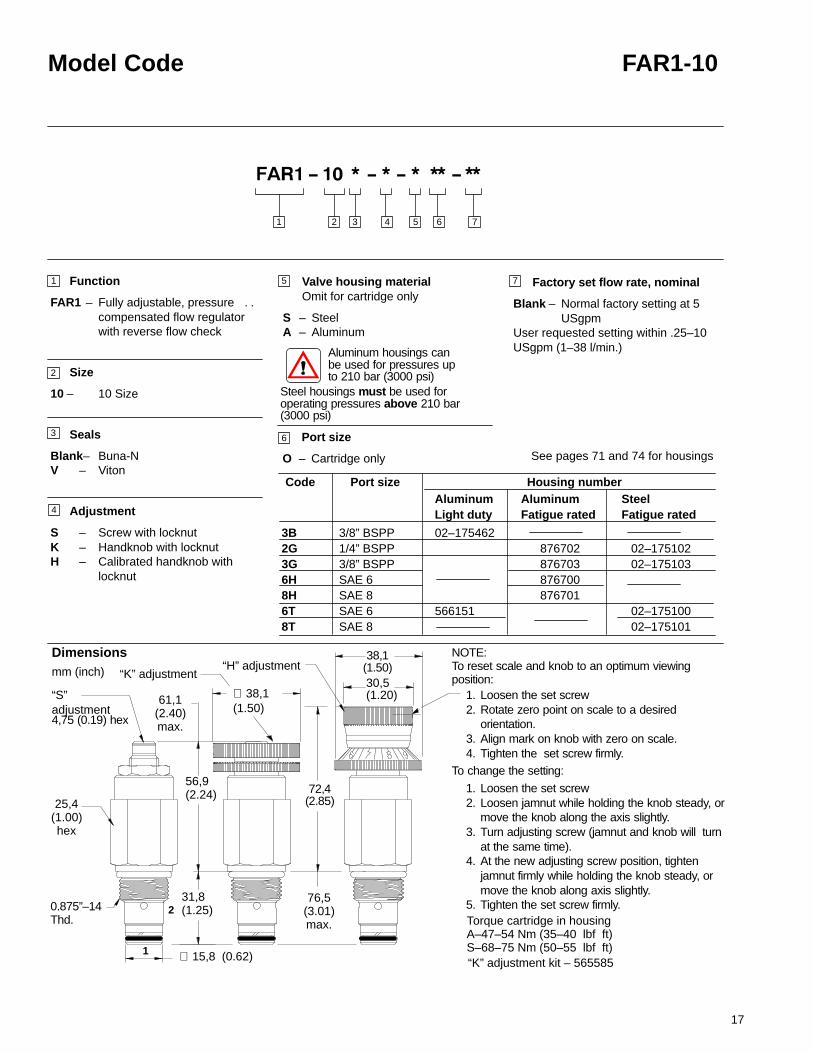
FAR1-10 Flow regulator, pressure compensated, fully adjustable
Sectional View
DescriptionThe FAR1–10 is a two-way, fully adjustable, pressure compensated, flow regulator,with free reverse flow, screw-in cartridge valve.
OperationThis valve maintains a constant flow from port 1 to port 2 regardless of pressurechanges upstream of port 1, or downstream of port 2. 13.8 bar (200 psi) must bemaintained across the valve to obtain pressure compensated control. The regulated flowbase within the adjusting range from 1 to 38 lpm (0.25 to 10 USgpm) is set by turningthe adjusting screws clockwise to decrease the flow and counter- clockwise to increasethe flow. This valve allows free reverse flow from port 2 to port 1.
Ratings and specificationsPerformance data is typical with fluid at 21,8 cSt (105 SUS) and 49�C (120�F)Typical application pressure (all ports) 5–350 bar (75–5000 psi) steel housing. . . . . . Min. pressure differential across valve 14 bar (200 psi). . . . . . . . . . . . . . . . . . . . . . . . . .
Cartridge fatigue pressure (infinite life) 310 bar (4500 psi). . . . . . . . . . . . . . . . . . . . . . . Rated flow 1–38 l/min (.25–10 USgpm). . . . . . . . . . . . . . . . . . . . . . . . . . . . . . . . . . . . . . . Flow regulation 4–38 l/min (1–10 USgpm) �10%. . . . . . . . . . . . . . . . . . . . . . . . . . . . . . . accuracy 1–4 l/min (0.25–1 USgpm) �20%Reverse check crack pressure 1.7 bar (25 psi). . . . . . . . . . . . . . . . . . . . . . . . . . . . . . . . Leakage at shutoff position 0.4 l/min (24.4 in3/min). . . . . . . . . . . . . . . . . . . . . . . . . . . . . .
Temperature range –40 to 120�C (–40� to 248�F). . . . . . . . . . . . . . . . . . . . . . . . . . . . Cavity C–10–2 (See page 68). . . . . . . . . . . . . . . . . . . . . . . . . . . . . . . . . . . . . . . . . . . . . . . Fluids All general purpose hydraulic fluids such as:. . . . . . . . . . . . . . . . . . . . . . . . . . . . .
MIL–H–5606, SAE 10, SAE 20, etc.Filtration Cleanliness code 18/16/13. . . . . . . . . . . . . . . . . . . . . . . . . . . . . . . . . . . . . . . . . . Standard housing materials Aluminum or steel. . . . . . . . . . . . . . . . . . . . . . . . . . . . . . . . . Weight cartridge only “S” 0,02 kg (0.44 lbs.). . . . . . . . . . . . . . . . . . . . . . . . . . . . . . . . . . . .
“K” 0,23 kg (0.51 lbs.)“H” 0,26 kg (0.59 lbs.)
Seal kits 565803 Buna-N. . . . . . . . . . . . . . . . . . . . . . . . . . . . . . . . . . . . . . . . . . . . . . . . . . . 566086 Viton
Viton is a registered trademark of E.I. DuPont
Performance Characteristics
Functional Symbol
Cartridge Only
2
1
10
12
6
8
Pressure differential across valve in psi
1000 2000 3000 4000 5000
70 140 210 280 350
40
32
24
16
8
Pressure differential across valve in bar
0
TYPICAL FLOW REGULATIONPRESSURE DROP FOR REVERSE FLOWFlow in lpm (21,8 cSt oil @ 49�C)
Flow in USgpm (105 SUS oil @ 120�F)
200
150
100
50
0 2 4 6 8 10 12
4
8
12
1
2
8 16 24 32 40
4
2
Flo
w in
lpm
(21,
8 cS
t oil
@ 4
9 C
)
�
Flo
w in
US
gp
m(1
05 S
US
oil
@ 1
20 F
)
°
17
Model Code FAR1-10
See pages 71 and 74 for housings
0.875”–14Thd.
31,8(1.25)2
“S” adjustment4,75 (0.19) hex
25,4(1.00)hex
∅ 15,8 (0.62)1
56,9(2.24)
61,1(2.40)max.
“K” adjustment“H” adjustment
30,5(1.20)
38,1(1.50)
72,4(2.85)
76,5(3.01)max.
∅ 38,1(1.50)
Function
FAR1 – Fully adjustable, pressure . . compensated flow regulator with reverse flow check
Size
10 – 10 Size
Seals
Blank– Buna-NV – Viton
Adjustment
S – Screw with locknutK – Handknob with locknutH – Calibrated handknob with
locknut
6
4
7
2 3 4 7651
1
2
3
5 Factory set flow rate, nominal
Blank – Normal factory setting at 5 USgpm
User requested setting within .25–10USgpm (1–38 l/min.)
Dimensionsmm (inch)
Aluminum housings can be used for pressures upto 210 bar (3000 psi)
Steel housings must be used foroperating pressures above 210 bar(3000 psi)
Valve housing materialOmit for cartridge only
S – Steel A – Aluminum
Torque cartridge in housingA–47–54 Nm (35–40 lbf ft)S–68–75 Nm (50–55 lbf ft)
NOTE:To reset scale and knob to an optimum viewingposition:
1. Loosen the set screw2. Rotate zero point on scale to a desired
orientation.3. Align mark on knob with zero on scale.4. Tighten the set screw firmly.
To change the setting:
1. Loosen the set screw2. Loosen jamnut while holding the knob steady, or
move the knob along the axis slightly.3. Turn adjusting screw (jamnut and knob will turn
at the same time).4. At the new adjusting screw position, tighten
jamnut firmly while holding the knob steady, or move the knob along axis slightly.
5. Tighten the set screw firmly.
“K” adjustment kit – 565585
Aluminum Aluminum SteelLight duty Fatigue rated Fatigue rated
3B 3/8” BSPP 02–1754622G 1/4” BSPP 876702 02–1751023G 3/8” BSPP 876703 02–1751036H SAE 6 8767008H SAE 8 8767016T SAE 6 566151 02–1751008T SAE 8 02–175101
Housing numberCode Port size
Port size
O – Cartridge only

18
FAR1-12 Flow regulator, pressure compensated, fully adjustable
Sectional View
DescriptionThe FAR1–12 is a two-way, fully adjustable, pressure compensated, flow regulator,with free reverse flow, screw-in cartridge valve.
OperationThis valve maintains a constant flow from port 1 to port 2 regardless of pressurechanges upstream of port 1, or downstream of port 2. 15,9 bar (230 psi) must bemaintained across the valve to obtain pressure compensated control. The regulated flowbase within the adjusting range from 1,5 to 94,5 lpm (0.4 to 25 USgpm) is set by turningthe adjusting screws clockwise to decrease the flow and counter- clockwise to increasethe flow. This valve allows free reverse flow from port 2 to port 1.
Ratings and specificationsPerformance data is typical with fluid at 21,8 cSt (105 SUS) and 49�C (120�F)Typical application pressure (all ports) 350 bar (5000 psi). . . . . . . . . . . . . . . . . . . . . . . Cartridge fatigue pressure (infinite life) 315 bar (4500 psi). . . . . . . . . . . . . . . . . . . . . . . Min. pressure differential across valve 15,9 bar (230 psi). . . . . . . . . . . . . . . . . . . . . . . . Max. pressure differential across valve 329 bar (4770 psi). . . . . . . . . . . . . . . . . . . . . . . Rated flow 1,5–94,5 l/min (.4–25 USgpm). . . . . . . . . . . . . . . . . . . . . . . . . . . . . . . . . . . . . Flow regulation accuracy 1,5–3,8 l/min (.4–1.0 USgpm) �20% @5000 psi. . . . . . . .
above 3,8–68,1 l/min (above 1–18 USgpm) �10% @3000 psiabove 68,1–94,6 l/min (above 18–25 USgpm) �15% @3000 psi
3,8–56,8 l/min (1–15 USgpm) �10% @5000 psiabove 56,8–89,1 l/min (above 15–23 USgpm) �15% @5000 psi
Reverse check crack pressure 1,7 bar (25 psi). . . . . . . . . . . . . . . . . . . . . . . . . . . . . . . . Leakage at shutoff position 0,5 l/min (30 in3/min). . . . . . . . . . . . . . . . . . . . . . . . . . . . . . . Temperature range –40 to 120�C (–40� to 248�F). . . . . . . . . . . . . . . . . . . . . . . . . . . . Cavity C–12–2 & C–12–2U (See page 68). . . . . . . . . . . . . . . . . . . . . . . . . . . . . . . . . . . . . Fluids All general purpose hydraulic fluids such as:. . . . . . . . . . . . . . . . . . . . . . . . . . . . .
MIL–H–5606, SAE 10, SAE 20, etc.Filtration Cleanliness code 18/16/13. . . . . . . . . . . . . . . . . . . . . . . . . . . . . . . . . . . . . . . . . . Standard housing materials Aluminum or steel. . . . . . . . . . . . . . . . . . . . . . . . . . . . . . . . . Weight cartridge only “S” 0,43 kg (0.98 lbs.). . . . . . . . . . . . . . . . . . . . . . . . . . . . . . . . . . . .
“K” 0,46 kg (1.0 lbs.)“H” 0,49 kg (1.1 lbs.)
Seal kits 02–181304 Buna-N. . . . . . . . . . . . . . . . . . . . . . . . . . . . . . . . . . . . . . . . . . . . . . . . 02–181305 Viton
Performance Characteristics
Functional Symbol
Cartridge Only
1
2
2
1
Viton is a registered trademark of E.I. DuPont
20
24
12
16
Pressure differential across valve in psi
1000 2000 3000 4000 5000
70 140 210 280 350
75
60
45
30
15
Pressure differential across valve in bar
0
TYPICAL FLOW REGULATIONPRESSURE DROP FOR REVERSE FLOWFlow in lpm (21,8 cSt oil @ 49�C)
Flow in USgpm (105 SUS oil @ 120�F)
200
150
100
50
0 4 8 12 16 20 24
4
8
12
15 30 45 60 75
8
4
9090
Flo
w in
lpm
(21,
8 cS
t oil
@ 4
9 C
)
°
Flo
w in
US
gp
m(1
05 S
US
oil
@ 1
20 F
)
°

19
Model Code FAR1-12
See pages 71 and 74 for housing dimensions
1.06”–12Thd.
44,7(1.76)2
“S” adjustment4,75 (0.19) hex
31,7(1.25)hex
∅ 23,7 (0.94)1
67,2(2.65)
73,1(2.88)max.
“K” adjustment“H” adjustment
30,5(1.20)
38,1(1.50)
82,6(3.25)
88,4(3.48)max.
∅ 38,1(1.50)
Port size
O – Cartridge only
Function
FAR1 – Fully adjustable, pressure . . compensated flow regulator with reverse flow check
Size
12 – 12 Size
Seals
Blank– Buna-NV – Viton
Adjustment
S – Screw with locknutK – Handknob with locknutH – Calibrated handknob with
locknut
6
4
7
2 3 4 7651
1
2
3
5 Factory set flow rate, nominal
Blank – Normal factory setting at 10USgpm
User requested setting Within 0.4–25 USgpm (1,5–94,6 l/min.)
up to 210 bar (3000 psi)Within 0.4–23 USgpm (1,5–87,1 l/min.)
up to 350 bar (5000 psi)
Dimensionsmm (inch)
Aluminum housings can be used for pressures upto 210 bar (3000 psi)
Steel housings must be used for operatingpressures above 210 bar (3000 psi)
Valve housing materialOmit for cartridge only
S – Steel A – Aluminum
Torque cartridge in housingA–81–95 Nm (60–70 lbf ft)S–102–115 Nm (75–85 lbf ft)
NOTE:To reset scale and knob to an optimum viewingposition:
1. Loosen the set screw2. Rotate zero point on scale to a desired
orientation.3. Align mark on knob with zero on scale.4. Tighten the set screw firmly.
To change the setting:
1. Loosen the set screw2. Loosen jamnut while holding the knob steady, or
move the knob along the axis slightly.3. Turn adjusting screw (jamnut and knob will turn
at the same time).4. At the new adjusting screw position, tighten
jamnut firmly while holding the knob steady, or move the knob along axis slightly.
5. Tighten the set screw firmly.
“K” adjustment kit – 565585
10T SAE 10 12T SAE 124G 1/2” BSPP6G 3/4” BSPP
Housing number
C-12-2Aluminum
C-12-2 Steel
02–16064002–16064402–16111802–161117
Fatigue rated
02–16974402–16978202–17206202–169665
C-12-2UAluminum
02–16064102–16064502–16111602–161115
Fatigue rated
C-12-2U Steel
02–16981702–16979002–17251202–162922
Code Port size
Fatigue rated

20
FAR1-16 Flow regulator, pressure compensated, fully adjustable
Sectional View
DescriptionThe FAR1–16 is a two-way, fully adjustable, pressure compensated, flow regulatorscrew-in cartridge valve.
OperationThis valve maintains a constant flow from port 1 to port 2 regardless of pressurechanges upstream of port 1, or downstream of port 2. 17 bar (250 psi) must bemaintained across the valve to obtain pressure compensated control. The regulated flowbase within the adjusting range from 3,8 to 113,6 lpm (1.0 to 30 USgpm) is set byturning the adjusting screws clockwise to decrease the flow and counter- clockwise toincrease the flow. This valve allows free reverse flow from port 2 to port 1.
Ratings and specificationsPerformance data is typical with fluid at 21,8 cSt (105 SUS) and 49�C (120�F)
Typical application pressure (all ports) 350 bar (5000 psi). . . . . . . . . . . . . . . . . . . . . Cartridge fatigue pressure (infinite life) 310 bar (4500 psi). . . . . . . . . . . . . . . . . . . . . Min. pressure differential across valve 17 bar (250 psi). . . . . . . . . . . . . . . . . . . . . . . Max. pressure differential across valve 328 bar (4750 psi). . . . . . . . . . . . . . . . . . . . .
Rated flow 3,8–113,6 l/min (1–30 USgpm). . . . . . . . . . . . . . . . . . . . . . . . . . . . . . . . .
Flow regulation accuracy 3,8–15,1 l/min (1.0–4.0 USgpm) �30% @5000 psi. . . . . above 15,1–30,3 l/min (above 4.0–8.0 USgpm) �20% @5000 psi
above 30,3–113,6 l/min (above 8.0–30.0 USgpm) �10% @5000 psi
Reverse check crack pressure 1,7 bar (25 psi). . . . . . . . . . . . . . . . . . . . . . . . . . . . .
Leakage at shutoff position 0,55 l/min (33.5 in3/min). . . . . . . . . . . . . . . . . . . . . . . . .
Temperature range –40 to 120�C (–40� to 248�F). . . . . . . . . . . . . . . . . . . . . . . . . .
Cavity C–16–2 (See page 68). . . . . . . . . . . . . . . . . . . . . . . . . . . . . . . . . . . . . . . . . .
Fluids All general purpose hydraulic fluids such as:. . . . . . . . . . . . . . . . . . . . . . . . . MIL–H–5606, SAE 10, SAE 20, etc.
Filtration Cleanliness code 18/16/13. . . . . . . . . . . . . . . . . . . . . . . . . . . . . . . . . . . . .
Standard housing materials Aluminum or steel. . . . . . . . . . . . . . . . . . . . . . . . . . . . .
Weight cartridge only “S” 0,67 kg (1.48 lbs.). . . . . . . . . . . . . . . . . . . . . . . . . . . . . . . “K” 0,70 kg (1.55 lbs.)“H” 0,74 kg (1.62 lbs.)
Seal kits 565810 Buna-N. . . . . . . . . . . . . . . . . . . . . . . . . . . . . . . . . . . . . . . . . . . . . . 889609 Viton
Performance Characteristics
Functional Symbol
Cartridge Only
2
1
Pressure differential across valve in psi
Pressure differential across valve in barTYPICAL FLOW REGULATIONPRESSURE DROP FOR REVERSE FLOW
Flow in lpm (21,8 cSt oil @ 49�C)
Flow in USgpm (105 SUS oil @ 120�F)
Viton is a registered trademark of E.I. DuPont
120
10080
60
40
20
36
30
24
18
12
6
100 240 300 350
1000 2000 3000 4000 5000
200
150
100
50
0 6 12 18 24 36
4
8
12
20 40 60 80 100 120
30
1
2

21
Model Code FAR1-16
Factory set flow rate
Blank – Normal factory setting at 15 USgpm
User requested setting Within 1–30 USgpm (3,8–113,6 l/min.)
4G 1/2” BSPP6B 3/4” BSPP6G 3/4” BSPP10T SAE 1010H SAE 1012T SAE 1212H SAE 12
Port size & valve bodiesO – Cartridge only
Function
FAR1 – Fully adjustable, pressure compensated flow regulator with reverse flow check
Size
16– 16 Size
Seals
Blank– Buna-NV – Viton
Adjustment
S – Screw with locknutK – Handknob with locknutH – Calibrated handknob with
locknut
6
4
2 3 4 7651
1
2
3
5
Aluminum housings can be used for pressures upto 210 bar (3000 psi)
Steel housings must be used for operatingpressures above 210 bar (3000 psi)
Valve housing materialOmit for cartridge only
S – Steel A – Aluminum
Torque cartridge in housingA-108–122 Nm (80–90) lbf ft)S-136–149 Nm (100–110 lbf ft)
NOTE:To reset scale and knob to an optimum viewingposition:
1. Loosen the set screw2. Rotate zero point on scale to a desired
orientation.3. Align mark on knob with zero on scale.4. Tighten the set screw firmly.
To change the setting:
1. Loosen the set screw2. Loosen jamnut while holding the knob steady,
or move the knob along the axis slightly.3. Turn adjusting screw (jamnut and knob will
turn at the same time).4. At the new adjusting screw position, tighten
jamnut firmly while holding the knob steady, or move the knob along axis slightly.
5. Tighten the set screw firmly.“K” adjustment kit – 02-185169
876716
876718
876717
566113
Housing numberSteel
Code Port size
02–175106
02–175107
02–175104
02–175105
Aluminum(fatigue rated)
7
See pages 71 and 74 for housings
30,5(1.20)
38,1(1.50)
“H” Adjustment“K” Adjustment
“S” Adjustment4,75 (0.19) hex
94,5(3.72)
101,9(4.01)max.
∅ 38,1(1.50)
82,1(3.40)79,1(3.11)
max.
38,1(1.50)hex
79,1(3.11)
1.312”–12 Thd.
28,5(1.12)
46,4(1.83)
Aluminum(light duty)
02–175463
566149

22
PFR5-8 Priority flow regulator, fixed
4000
Sectional View
DescriptionThe PFR5–8 is a fixed orifice, priority type, pressure compensated, flow regulator,screw-in cartridge valve.
OperationThis valve maintains a constant, factory-set, priority flow from port 1 to port 3 basedon 5.5 bar (80 psid) regardless of pressure changes downstream on port 3. Flow inexcess of the priority setting is directed to port 2. If the priority flow at port 3 isblocked, the spool will shift to try and satisfy the priority flow requirement, therebyclosing off flow to port 2.
Ratings and specificationsPerformance data is typical with fluid at 21,8 cSt (105 SUS) and 49�C (120�F)Typical application pressure (all ports) 350 bar (5000 psi) steel housing. . . . . . . . . .
210 bar (3000 psi) aluminum housingCartridge fatigue pressure (infinite life) 280 bar (4000 psi). . . . . . . . . . . . . . . . . . . . . . Rated flow maximum inlet flow 15,1 l/min (4 USgpm). . . . . . . . . . . . . . . . . . . . . . . . . .
maximum regulated flow 10 l/min (2.5 USgpm)Internal leakage 82 cm3/min. @ 350 bar (3000 psi) 5 in3/min @ 5000 psi). . . . . . . . . Flow regulationaccuracy 0,4–1,9 l/min (0.1–0.49 USgpm) �20% @ 210 bar (3000 psi). . . . . . . . .
0,4–1,9 l/min (0.1–0.49 USgpm) �40% @ 350 bar (5000 psi)1,9–5,7 l/min (0.5–1.49 USgpm) �15% @ 350 bar (5000 psi)5,7–10 l/min (1.5–2.5 USgpm) �10% @ 350 bar (5000 psi)
Factory set maximum priority flow rate accuracy under standard test conditions and within the above ranges
Temperature range -40 to 120�C (-40� to 248�F). . . . . . . . . . . . . . . . . . . . . . . . . . . . .
Cavity C–8–3 (See page 69). . . . . . . . . . . . . . . . . . . . . . . . . . . . . . . . . . . . . . . . . . . . . . . . Fluids All general purpose hydraulic fluids such as:. . . . . . . . . . . . . . . . . . . . . . . . . . . .
MIL–H–5606, SAE 10, SAE 20, etc.Filtration Cleanliness code 18/16/13. . . . . . . . . . . . . . . . . . . . . . . . . . . . . . . . . . . . . . . . . Standard housing materials Aluminum or steel. . . . . . . . . . . . . . . . . . . . . . . . . . . . . . . . Weight cartridge only 0,07 kg (0.15 lb.). . . . . . . . . . . . . . . . . . . . . . . . . . . . . . . . . . . . . . . Seal kits 02–173427 Buna-N. . . . . . . . . . . . . . . . . . . . . . . . . . . . . . . . . . . . . . . . . . . . . . .
02–173434 VitonViton is a registered trademark of E.I. DuPont
Typical Flow Regulation
10
8
6
4
2
5000
350
4000
280
3000
210
2000
140
1000
70
0 5000300020001000
0 70 140 210 280 350
0
3
2
1
Bypass pressurehigher than priority
Priority pressurehigher than bypass
Functional Symbol
Cartridge Only
Pressure bar
Pressure psi
3.0
2.5
2.0
1.5
1.0
0.5
0
12
3
2
1
Flo
w in
lpm
(21,
8 cS
t oil
@ 4
9 C
)
°
Flo
w in
US
gp
m(1
05 S
US
oil
@ 1
20 F
)
°

23
Model Code PFR5-8
Function
PFR5– Priority flow regulator
Size
8 – 8 Size
Seals
Blank– Buna-NV – Viton
Adjustment
F – Fixed orifice
Valve housing materialOmit for cartridge only
S – Steel A – Aluminum
2 3 4 7651
1
2
3
4
5
7
6
2
3
1
22,1 (.870) hex
0.750″–16 Thd.
∅ 15,8 (0.622)
∅ 14,2 (0.559)
Factory set flow rate, nominal
(Specify in USgpm)Range 0,4–9,5 l/min (0.1–2.5 USgpm)
Example:0.5– 1,9 l/pm (0.5 USgpm)
40,6(1.60)
Dimensionsmm (inch)
4T SAE 4 6T SAE 6 2G 1/4” BSPP3G 3/8” BSPP
Housing number
Aluminum Steel
02–16074102–16074202–16073902–160740
Fatigue rated
02–16074502–16074602–16074302–160744
Code Port size
Port size
O – Cartridge only
8,5(0.33)
Fatigue rated
Torque cartridge in housing 34–41 Nm (25–30 lbf ft)
See pages 72 and 74 for housings
Aluminum housings can be used for pressures upto 210 bar (3000 psi)
Steel housings must be used foroperating pressures above 210 bar(3000 psi)

24
PFR5-10 Priority flow regulator, fixed
Sectional View
DescriptionThe PFR5-10-F is a fixed orifice, priority type, pressure compensated, flow regulatorscrew-in cartridge valve .
OperationThis valve maintains a constant, factory-set, priority flow from port 1 to port 3 basedon 5.5 bar (80 psid) regardless of pressure changes downstream on port 3. Flow inexcess of the priority setting is directed to port 2. If the priority flow at port 3 isblocked, the spool will shift to satisfy the priority flow requirement, thereby closing offflow to port 2.
Ratings and specificationsPerformance data is typical with fluid at 21,8 cSt (105 SUS) and 49�C (120�F)Typical application pressure (all ports) 350 bar (5000 psi). . . . . . . . . . . . . . . . . . . . . . . Cartridge fatigue pressure (infinite life) 280 bar (4000 psi). . . . . . . . . . . . . . . . . . . . . . . Rated flow Maximum inlet flow 60 l/min (15 USgpm). . . . . . . . . . . . . . . . . . . . . . . . . . .
Maximum regulated flow 23 l/min (6 USgpm)Flow regulationaccuracy 0,4–1,9 l/min (0.1–0.49 USgpm) �20% @ 210 bar (3000 psi). . . . . . . . .
0,4–1,9 l/min (0.1–0.49 USgpm) �40% @ 350 bar (5000 psi)1,9–5,7 l/min (0.5–1.49 USgpm) �15% @ 350 bar (5000 psi)5,7–22,7 l/min (1.5–6 USgpm) �10% @ 350 bar (5000 psi)
Factory set maximum priority flow rate accuracy under standard test conditions and within the above ranges
Temperature range -40 to 120�C (-40� to 248�F). . . . . . . . . . . . . . . . . . . . . . . . . . . . . .
Cavity C–10–3 (See page 69). . . . . . . . . . . . . . . . . . . . . . . . . . . . . . . . . . . . . . . . . . . . . . . Fluids All general purpose hydraulic fluids such as:. . . . . . . . . . . . . . . . . . . . . . . . . . . . .
MIL–H–5606, SAE 10, SAE 20, etc.Filtration Cleanliness code 18 /16/13. . . . . . . . . . . . . . . . . . . . . . . . . . . . . . . . . . . . . . . . . . Standard housing materials Aluminum or steel. . . . . . . . . . . . . . . . . . . . . . . . . . . . . . . . . Weight cartridge only 0,13 kg (0.28 lb.). . . . . . . . . . . . . . . . . . . . . . . . . . . . . . . . . . . . . . . . Seal kits 565804 Buna-N. . . . . . . . . . . . . . . . . . . . . . . . . . . . . . . . . . . . . . . . . . . . . . . . . . . .
889599 VitonViton is a registered trademark of E.I. DuPont
Typical Flow Regulation
Functional Symbol
3
2
1
Cartridge Only
3
2
1
4000
20
16
12
8
4
5000
350
4000
280
3000
210
2000
140
1000
70
0 5000300020001000
0 70 140 210 280 350
0
Bypass pressurehigher than priority
Priority pressurehigher than bypass
Pressure bar
Pressure psi
6.0
5.0
4.0
3.0
2.0
1.0
0
24
Flo
w in
lpm
(21,
8 cS
t oil
@ 4
9 C
)
°
Flo
w in
US
gp
m(1
05 S
US
oil
@ 1
20 F
)
°

25
Model Code PFR5-10
Housing material
A – AluminumS – Steel
Function
PFR5 – Priority flow regulator
Size
10 – 10 Size
Seals
Blank – Buna-NV – Viton
Adjustment
F – Fixed orifice
Dimensionsmm (inch)
2 3 4 651
1
2
3
5 Factory set flow rate
(Specify in USgpm)Range 0,38–22,7 l/min (0.1–6.0 USgpm)
Port size
O – Cartridge only
.
7
4
6
Aluminum housings can be used for pressures upto 210 bar (3000 psi)
Steel housings must be used foroperating pressures above 210 bar(3000 psi)
7
Torque cartridge in housingA–47–54 Nm (35–40 lbf ft)S–68–75 Nm (50–55 lbf ft)
20,8(0.82)
46,0(1.81)
25,4 (1.0) hex
0.875″-14 Thd.
∅ 15,82 (0.623)
∅ 17,42 (0.686)
3
2
1
876705
876714
876704876711
02-173358
566162
Housing number
Aluminum(light duty Steel
Code Port size
2G3B3G6T6H8H8T
02-175127
02-17512802–175124
02–175125
Aluminum(fatigue rated)
1/4” BSPP 3/8” BSPP3/8” BSPPSAE 6 SAE 6 SAE 8SAE 8
See pages 72 and 74 for housings

26
PFR1-16 Priority flow regulator, fixed
Sectional View
DescriptionThe PFR1-16-F is a fixed orifice, priority type, pressure compensated, flow regulatorscrew-in cartridge valve .
OperationThis valve maintains a constant, factory-set, priority flow from port 1 to port 3 basedon 5.5 bar (80 psid) regardless of pressure changes downstream on port 3. Flow inexcess of the priority setting is directed to port 2. If the priority flow at port 3 isblocked, the spool will shift to satisfy the priority flow requirement, thereby closing offflow to port 2.
Ratings and specificationsPerformance data is typical with fluid at 21,8 cSt (105 SUS) and 49�C (120�F)Typical application pressure (all ports) 210 bar (3000 psi). . . . . . . . . . . . . . . . . . . . . . . Cartridge fatigue pressure (infinite life) 210 bar (3000 psi). . . . . . . . . . . . . . . . . . . . . . . Rated flow Maximum inlet flow 151 l/min (40 USgpm). . . . . . . . . . . . . . . . . . . . . . . . . .
Maximum regulated flow 114 l/min (30 USgpm)Flow regulation accuracy 1,9–10,9 l/min (0.5–2.9 USgpm) �15%. . . . . . . . . . . . . . . .
11,4–114 l/min (3–30 USgpm) �10%Factory set maximum priority flow rate accuracy under standard test conditions and within the above ranges
Temperature range -40 to 120�C (-40� to 248�F). . . . . . . . . . . . . . . . . . . . . . . . . . . . . . Cavity C–16–3 (See page 69). . . . . . . . . . . . . . . . . . . . . . . . . . . . . . . . . . . . . . . . . . . . . . . Fluids All general purpose hydraulic fluids such as:. . . . . . . . . . . . . . . . . . . . . . . . . . . . .
MIL–H–5606, SAE 10, SAE 20, etc.Filtration Cleanliness code 18/16/13. . . . . . . . . . . . . . . . . . . . . . . . . . . . . . . . . . . . . . . . . . Standard housing materials Aluminum. . . . . . . . . . . . . . . . . . . . . . . . . . . . . . . . . . . . . . . . Weight cartridge only 0,38 kg (0.84 lb.). . . . . . . . . . . . . . . . . . . . . . . . . . . . . . . . . . . . . . . . Seal kits 565811 Buna-N. . . . . . . . . . . . . . . . . . . . . . . . . . . . . . . . . . . . . . . . . . . . . . . . . . . .
889610 VitonViton is a registered trademark of E.I. DuPont
Typical Flow Regulation
Functional Symbol
120
100
80
60
40
20
0
30
25
20
15
10
5
0
70 140 175 210
0 1000 2000500 1500 2500-Port 3, priority (regulated)outlet pressurized
-Port 2, bypass outletpressurized
Back Pressure psi
Back Pressure bar
0
3
2
1
Cartridge Only
A
B
A
B
A
B
3
2
1
3000
10035
Pri
ori
ty f
low
rat
e in
lpm
(21,
8 cS
t oil
@ 4
9 C
)
°
Pri
ori
ty f
low
rat
e in
US
gp
m(1
05 S
US
oil
@ 1
20 F
)
°

27
Model Code PFR1-16
Function
PFR1– Priority flow regulator
Size
16 – 16 Size
Seals
Blank– Buna-NV – Viton
Adjustment
F – Fixed orifice
3
2
1
2 3 4 651
1
2
3
4
5
6 Factory set flow rate, nominal
(Specify in USgpm)Range 1,9–114 l/min (0.5–30 USgpm)
25,4(1.00)
73,0(2.87)
38,1 (1.50) hex
1.312″-12 Thd.
∅ 26,95 (1.061)
∅ 28,55 (1.124)
Dimensionsmm (inch)
.
12T SAE 126B 3/4” BSPP10H SAE 1012H SAE 124G 1/2” BSPP6G 3/4” BSPP
Housing number
Aluminum
56615202–175465
Light duty
Code Port size
AluminumFatigue rated
876721876723876720876722
Port size
O – Cartridge only
Torque cartridge in housing108–122 Nm (80–90 lbf ft)
See pages 72 for housings

28
PFR2-10 Priority flow regulator,adjustable
3
Sectional View
DescriptionThe PFR2-10 is a limited range adjustable*, pressure compensated, priority type,flow regulator screw-in cartridge valve.*The flow adjustment is from the factory set maximum flow rate down to 50% of that
factory set flow rate.
OperationThis valve maintains a constant, factory-set, priority flow from port 1 to port 3 basedon the setting adjustment, regardless of pressure changes downstream on port 3.Flow in excess of the priority setting is directed to port 2. If the priority flow at port 3 isblocked, the spool will shift to satisfy the priority flow requirement, thereby closing offflow to port 2.
Ratings and specificationsPerformance data is typical with fluid at 21,8 cSt (105 SUS) and 49�C (120�F)Typical application pressure (all ports) 210 bar (3000 psi). . . . . . . . . . . . . . . . . . . . . . . Cartridge fatigue pressure (infinite life) 210 bar (3000 psi). . . . . . . . . . . . . . . . . . . . . . . Rated flow Maximum inlet flow 60 l/min (15 USgpm). . . . . . . . . . . . . . . . . . . . . . . . . . .
Maximum regulated flow 38 l/min (10 USgpm)Flow regulation accuracy 0,4–1,9 l/min (0.1–0.49 USgpm) �20%. . . . . . . . . . . . . . . .
1,9–7,5 l/min (0.5–1.99 USgpm) �15%7,6–37,8 l/min (2.0–10.0 USgpm) �10%
Factory set maximum priority flow rate accuracy under standard test conditions and within the above ranges
Temperature range -40 to 120�C (-40� to 248�F). . . . . . . . . . . . . . . . . . . . . . . . . . . . . . Cavity C–10–3 (See page 69). . . . . . . . . . . . . . . . . . . . . . . . . . . . . . . . . . . . . . . . . . . . . . . Fluids All general purpose hydraulic fluids such as:. . . . . . . . . . . . . . . . . . . . . . . . . . . . .
MIL–H–5606, SAE 10, SAE 20, etc.Filtration Cleanliness code 18/16/13. . . . . . . . . . . . . . . . . . . . . . . . . . . . . . . . . . . . . . . . . . Standard housing materials Aluminum. . . . . . . . . . . . . . . . . . . . . . . . . . . . . . . . . . . . . . . . Weight cartridge only 0,25 kg (0.54 lb.). . . . . . . . . . . . . . . . . . . . . . . . . . . . . . . . . . . . . . . . Seal kits 565804 Buna-N. . . . . . . . . . . . . . . . . . . . . . . . . . . . . . . . . . . . . . . . . . . . . . . . . . . .
889599 VitonViton is a registered trademark of E.I. DuPont
Typical Flow Regulation
Functional Symbol
2
1
-Port 3, priority (regulated)outlet pressurized
-Port 2, bypass outletpressurized
40
30
20
10
0
9
6
3
0
35 100 175 210
0 1000 2000500 1500 2500
Back Pressure psi
Back Pressure bar
0
3
2
1
Cartridge Only
A
B
A
B
B
A
3000
14070
Pri
ori
ty (r
egu
late
d) f
low
rat
e in
lpm
(21,
8 cS
t oil
@ 4
9 C
)
°
Pri
ori
ty (
reg
ula
ted
) flo
w r
ate
in U
Sg
pm
(105
SU
S o
il @
120
F)
°

29
Model Code PFR2-10
Function
PFR2– Priority flow regulator
Size
10 – 10 Size
Seals
Blank – Buna-NV – Viton
Adjustment
C – CapK – KnobS – Screw
Dimensionsmm (inch)
2 3 4 651
1
2
3
4
5
6 Factory set flow rate, nominal
(Specify in USgpm)Range 0,38–37,8 l/min (0.1–10.0 USgpm)
“K” Adjustment∅ 38,1 (1.50)
25,4 (1.0) hex
15,80 (0.622)
17,40 (0.685)
80,0(3.15)
0.875″-14 Thd.
46,0(1.81)
“C” Adjustment19,0 (0.75) hex
3
2
1∅
∅
.
3B 3/8” BSPP 6T SAE 6 2G 1/4” BSPP3G 3/8” BSPP6H SAE 6 8H SAE 8
Housing number
Aluminum
02–173358566162
Light duty
876705876714876704876711
Code Port size
AluminumFatigue rated
Torque cartridge in housing47–54 Nm (35–40 lbf ft)
“S” Adjustment4,8 (0.18) hex
Port size
O – Cartridge only
See pages 72 for housings

30
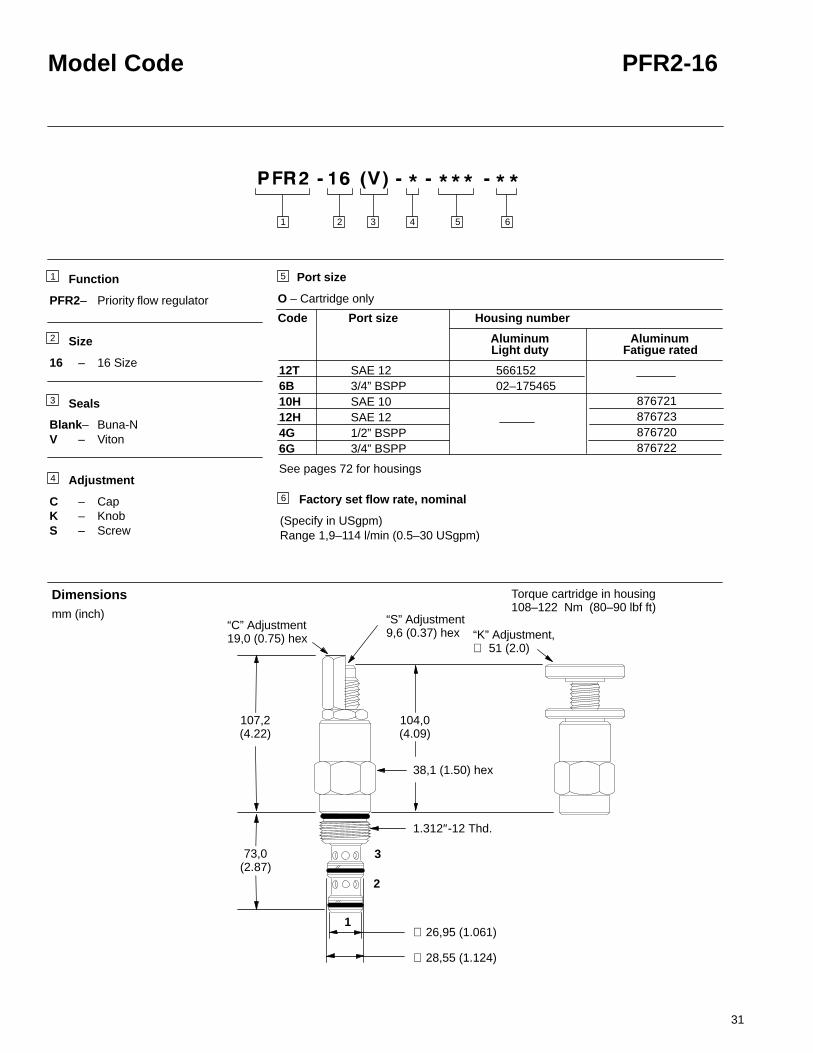
PFR2-16 Priority flow regulator, adjustable
DescriptionThe PFR2-16 is a limited range adjustable*, priority type, pressure compensated,flow regulator screw-in cartridge valve.*The flow adjustment is from the factory set maximum flow rate down to 50% of that
factory set flow rate.
OperationThis valve maintains a constant, factory-set, priority flow from port 1 to port 3 basedon based on the setting adjustment, regardless of pressure changes downstream onport 3. Flow in excess of the priority setting is directed to port 2. If the priority flow atport 3 is blocked, the spool will shift to satisfy the priority flow requirement, therebyclosing off flow to port 2.
Ratings and specificationsPerformance data is typical with fluid at 21,8 cSt (105 SUS) and 49�C (120�F)Typical application pressure (all ports) 210 bar (3000 psi). . . . . . . . . . . . . . . . . . . . . . . Cartridge fatigue pressure (infinite life) 210 bar (3000 psi). . . . . . . . . . . . . . . . . . . . . . . Rated flow Maximum inlet flow 151 l/min (40 USgpm). . . . . . . . . . . . . . . . . . . . . . . . . .
Maximum regulated flow 114 l/min (30 USgpm)Flow regulation accuracy 1,9–10,9 l/min (0.5–2.9 USgpm) �15%. . . . . . . . . . . . . . . .
11,4–114 l/min (3–30 USgpm) �10%Factory set maximum priority flow rate accuracy under standard test conditions and within the above ranges
Temperature range -40 to 120�C (-40� to 248�F). . . . . . . . . . . . . . . . . . . . . . . . . . . . . . Cavity C–16–3 (See page 69). . . . . . . . . . . . . . . . . . . . . . . . . . . . . . . . . . . . . . . . . . . . . . . Fluids All general purpose hydraulic fluids such as:. . . . . . . . . . . . . . . . . . . . . . . . . . . . .
MIL–H–5606, SAE 10, SAE 20, etc.Filtration Cleanliness code 18/16/13. . . . . . . . . . . . . . . . . . . . . . . . . . . . . . . . . . . . . . . . . . Standard housing materials Aluminum. . . . . . . . . . . . . . . . . . . . . . . . . . . . . . . . . . . . . . . . Weight cartridge only 0,43 kg (0.95 lb.). . . . . . . . . . . . . . . . . . . . . . . . . . . . . . . . . . . . . . . . Seal kits 565811 Buna-N. . . . . . . . . . . . . . . . . . . . . . . . . . . . . . . . . . . . . . . . . . . . . . . . . . . .
889610 VitonViton is a registered trademark of E.I. DuPont
Typical Flow Regulation
Functional Symbol
Sectional View
-Port 3, priority (regulated)outlet pressurized
-Port 2, bypass outletpressurized
0 1000 2000500 1500 2500
25
20
15
10
5
0
100
80
60
40
20
0
75 100 175 210
Back Pressure psi
Back Pressure bar0Cartridge Only
3
2
1
3000A
B
A
B
A
B
3
2
1
14035
Pri
ori
ty (r
egu
late
d) f
low
rat
e in
lpm
(21,
8 cS
t oil
@ 4
9 C
)
°
Pri
ori
ty (
reg
ula
ted
) flo
w r
ate
in U
Sg
pm
(105
SU
S o
il @
120
F)
°
31
Model Code PFR2-16
Function
PFR2– Priority flow regulator
Size
16 – 16 Size
Seals
Blank– Buna-NV – Viton
Adjustment
C – CapK – KnobS – Screw
3
2
1
2 3 4 651
1
2
3
4
5
6 Factory set flow rate, nominal
(Specify in USgpm)Range 1,9–114 l/min (0.5–30 USgpm)
“K” Adjustment,∅ 51 (2.0)
38,1 (1.50) hex
26,95 (1.061)
28,55 (1.124)
104,0(4.09)
1.312″-12 Thd.
73,0(2.87)
∅
∅
Dimensionsmm (inch)
12T SAE 126B 3/4” BSPP10H SAE 1012H SAE 124G 1/2” BSPP6G 3/4” BSPP
Housing number
Aluminum
56615202–175465
Light duty
Code Port size
AluminumFatigue rated
876721876723876720876722
Port size
O – Cartridge only
Torque cartridge in housing108–122 Nm (80–90 lbf ft)
“S” Adjustment9,6 (0.37) hex
107,2(4.22)
“C” Adjustment19,0 (0.75) hex
See pages 72 for housings

32
MRV2-10 Manual rotary valve
Sectional View
DescriptionThe MRV2-10 is a 2-way, 2 position, manual semi-rotary screw-in flow restrictor valve .
OperationThis valve will increase or decrease flow by changing the variable orifice with therotary adjustment. Recommended flow path is P to 2, out 1.
Ratings and specificationsPerformance data is typical with fluid at 21,8 cSt (105 SUS) and 49�C (120�F)Typical application pressure (all ports) 210 bar (3000 psi). . . . . . . . . . . . . . . . . . . . . . . Rated flow 05 – 0-18,9 l/min (0–5 USgpm). . . . . . . . . . . . . . . . . . . . . . . . . . . . . . . . . . .
10 – 0-37,8 l/min (0–10 USgpm)15 – 0-56,7 l/min (0–15 USgpm)
Internal leakage 164 cm3/min. (10 in3/min. . . . . . . . . . . . . . . . . . . . . . . . . . . . . . . . . . . . . maximum 210 bar (3000 psi)
Temperature range -40 to 120�C (-40� to 248�F). . . . . . . . . . . . . . . . . . . . . . . . . . . . . . Manual operators B – Ball lever (friction lock)*. . . . . . . . . . . . . . . . . . . . . . . . . .
E – Ball lever (10 position detent)*D – Lever (10 position detent)*L – Lever (friction lock)*K – Knob (non-locking)
Cavity C–10–2 (See page 68). . . . . . . . . . . . . . . . . . . . . . . . . . . . . . . . . . . . . . . . . . . . . . . Fluids All general purpose hydraulic fluids such as:. . . . . . . . . . . . . . . . . . . . . . . . . . . . .
MIL–H–5606, SAE 10, SAE 20, etc.Filtration Cleanliness code 18/16/13. . . . . . . . . . . . . . . . . . . . . . . . . . . . . . . . . . . . . . . . . . Standard housing materials Aluminum. . . . . . . . . . . . . . . . . . . . . . . . . . . . . . . . . . . . . . . . Weight cartridge only 0,79 kg (1.74 lb.). . . . . . . . . . . . . . . . . . . . . . . . . . . . . . . . . . . . . . . . Seal kits 561810 Buna-N. . . . . . . . . . . . . . . . . . . . . . . . . . . . . . . . . . . . . . . . . . . . . . . . . . . .
889609 Viton�Viton is a registered trademark of E.I. DuPont
*Light duty housings only
Pressure Drop Curves
Functional Symbol
A BC
9
8
7
6
5
4
3
2
1
0
10 20 30 40 50 60
0 2 4 6 8 10 12 14
Kn
ob
leve
r p
osi
tio
n
2
1
Flow in USgpm (105 SUS oil @ 120�F)
Flow in l/min (21,8 cSt oil @ 49�C)
-05-10-15
ABC
Cartridge only
@ 5,5 bar (80 psi) pressure drop andunder standardconditions.
P 2 1
Rated flow

33
Model Code MRV2-10
Function
MRV2– Manual rotary valve
Size
10 – 10 Size
Seals
Blank– Buna-NV – Viton
Manual operators
0 – No operatorB – Ball lever (friction lock)*E – Ball lever (10 position detent)*D – Lever (10 position detent)*L – Lever (friction lock)*K – Knob (non-locking)* Light duty housings only.
∅ 3,45-3,50(#29 or 0.136+0.002)� 4,76 (0.187)
0
MRV2-10-KKnob Operated
Arrow can be re-located byslacking the plate. Re-tighten nut.
2 3 4 51
1
2
3
4
5
37,0(1.45)
31,7(1.25)
15,80 (0.622)
25,4 (1.00) hex
0.875″-14 Thd.
MRV2-10-B/E Models
41,0(1.60)
38,1(1.50)
41,0(1.60)
X X
58,0(2.28)X X
17,0(0.67)
Locatingpin hole
MRV2-10-D/L Models
MRV2-10-E/D Models MRV2-10-B/L Models
Locatingpin hole
in mating housing
2
1
Dimensionsmm (inch)
6
6 Max flow ranges (nominal)
05 – 0-18,9 l/min (0–5 USgpm)10 – 0-37,8 l/min (0–10 USgpm)15 – 0-56,7 l/min (0–15 USgpm)
3B 3/8” BSPP 6T SAE 6 2G 1/4” BSPP3G 3/8” BSPP6H SAE 6 8H SAE 8
Housing number
Aluminum
02–175462566151
Light duty
876702876703876700876701
Code Port size
AluminumFatigue rated
42,0(1.65)
Torque cartridge in housing47–54 Nm (35–40 lbf ft)
∅
∅ 25,4 (1.00)
42,0(1.65)
See page 71 for housings
Port size
O – Cartridge only

34
MRV2-16 Manual rotary valve
DescriptionThe MRV2-16 is a 2-way, 2 position, manual semi-rotary screw-in flow restrictor valve.
OperationThis valve will increase or decrease flow by changing the variable orifice with therotary adjustment. Recommended flow path is P to 2 out 1.
Ratings and specificationsPerformance data is typical with fluid at 21,8 cSt (105 SUS) and 49�C (120�F)Typical application pressure (all ports) 210 bar (3000 psi). . . . . . . . . . . . . . . . . . . . . . . . . Rated flow 10 – 0-37,8 l/min (0–10 USgpm) 30 – 0-113,5 l/min (0–30 USgpm). .
15 – 0-56,7 l/min (0–15 USgpm) 35 – 0-132,4 l/min (0–35 USgpm)20 – 0-75,7 l/min (0–20 USgpm) 40 – 0-151,4 l/min (0–40 USgpm)25 – 0-94,6 l/min (0–25 USgpm) 45 – 0-170,3 l/min (0–45 USgpm)
Internal leakage 82 cm3/min. (5 in3/min. . . . . . . . . . . . . . . . . . . . . . . . . . . . . . . . . . . . . . . . . maximum 210 bar (3000 psi)
Temperature range -40 to 120�C (-40� to 248�F). . . . . . . . . . . . . . . . . . . . . . . . . . . . . . . Manual operators D – Lever (10 position detent)*. . . . . . . . . . . . . . . . . . . . . . . . . . . . . . .
L – Lever (friction lock)*K – Knob (non-locking)
Cavity C–16–2 (See page 68). . . . . . . . . . . . . . . . . . . . . . . . . . . . . . . . . . . . . . . . . . . . . . . . . Fluids All general purpose hydraulic fluids such as:. . . . . . . . . . . . . . . . . . . . . . . . . . . . . .
MIL–H–5606, SAE 10, SAE 20, etc.Filtration Cleanliness code 18/16/13. . . . . . . . . . . . . . . . . . . . . . . . . . . . . . . . . . . . . . . . . . . Standard housing materials Aluminum. . . . . . . . . . . . . . . . . . . . . . . . . . . . . . . . . . . . . . . . . Weight cartridge only 0,79 kg (1.74 lb.). . . . . . . . . . . . . . . . . . . . . . . . . . . . . . . . . . . . . . . . . Seal kits 561810 Buna-N. . . . . . . . . . . . . . . . . . . . . . . . . . . . . . . . . . . . . . . . . . . . . . . . . . . . .
889609 Viton�Viton is a registered trademark of E.I. DuPont
*Light duty housings only
Pressure Drop Curves
Functional Symbol
9
8
7
6
5
4
3
2
1
20 40 60 80 100 120 140 160 180
0 4 8 12 16 20 24 28 32 36 40 44
A B C D E G H
Sectional View
Kn
ob
leve
r p
osi
tio
n
Flow in USgpm (105 SUS oil @ 120�F)
Flow in l/min (21,8 cSt oil @ 49�C)
2
1
F
Cartridge only
@ 5,5 bar (80 psi)pressure drop andunder standardconditions.
2 1
Rated flow
P
E -30F -35G -40H -455
A -10B -15C -20D -25

35
Model Code MRV2-16
Max flow ranges (nominal)10 – 0-37,8 l/min (0–10 USgpm) 30 – 0-113,5 l/min (0–30 USgpm)15 – 0-56,7 l/min (0–15 USgpm) 35 – 0-132,4 l/min (0–35 USgpm)20 – 0-75,7 l/min (0–20 USgpm) 40 – 0-151,4 l/min (0–40 USgpm)25 – 0-94,6 l/min (0–25 USgpm) 45 – 0-170,3 l/min (0–45 USgpm)
Function
MRV2– Manual rotary valve
Size
16 – 16 Size
Seals
Blank– Buna-NV – Viton
Manual operators
0 – No operatorD – Lever (10 position detent)*L – Lever (friction lock)*K – Knob (non-locking)* Light duty housings only.
2
1
2 3 4 51
1
2
3
4
5
Dimensionsmm (inch)
MRV2-16-KKnob Operated
6,0(2.40)
44,4(1.75)
46,0(1.81)
28,55 (1.124)
38,1 (1.50) hex
1.312″-12 Thd.
58,0(2.28)
76,0(3.00)X X
24,8(0.98)
Locatingpin hole
MRV2-16-D/L Models
MRV2-16-D Models MRV2-16-L Models
Locatingpin hole
6
6
6B 3/4” BSPP 12T SAE 12 4G 1/2” BSPP6G 3/4” BSPP10H SAE 1012H SAE 12
Housing number
Aluminum
02–175463566149
Light duty
Code Port size
AluminumFatigue rated
Port size
O – Cartridge only
Torque cartridge in housing108–122 Nm (80–90 lbf ft)
∅
∅ 3,45-3,50(#29 or 0.136+0.002)� 4,76 (0.187)
0
in mating housing
See page 71 for housings
876716876718876717566113

36
NV1-8 Needle valve
50 100
50
100
150
2000 20 30 40
0
Pre
ssu
re D
rop
psi
Pre
ssu
re D
rop
bar
Flow in l/min (21,8 cSt oil @ 49�C)
4
8
12
12
10
Sectional View
DescriptionThe NV1–8 is a direct-acting, adjustable, screw-in cartridge type needle valve.
OperationThis needle valve is non-pressure compensated. Flow is controlled in either direction,from full flow to tight shut-off, by turning the adjustment feature clockwise.
Ratings and specificationsPerformance data is typical with fluid at 21,8 cSt (105 SUS) and 49�C (120�F)
Typical application pressure (all ports) 350 bar (5000 psi) steel housing. . . . . . . . . . 210 bar (3000 psi) aluminum housing
Cartridge fatigue pressure (infinite life) 280 bar (4000 psi). . . . . . . . . . . . . . . . . . . . .
Rated flow 45 l/min (12 USgpm). . . . . . . . . . . . . . . . . . . . . . . . . . . . . . . . . . . . . . . . . . .
Internal leakage 5 drops/min. maximum @ 350 bar (5000 psi). . . . . . . . . . . . . . . . . .
Temperature range -40 to 120�C (-40� to 248�F). . . . . . . . . . . . . . . . . . . . . . . . . . . .
Cavity C–8–2 (See page 68). . . . . . . . . . . . . . . . . . . . . . . . . . . . . . . . . . . . . . . . . . . . . . .
Fluids All general purpose hydraulic fluids such as:. . . . . . . . . . . . . . . . . . . . . . . . . . . MIL–H–5606, SAE 10, SAE 20, etc.
Filtration Cleanliness code 18/16/13. . . . . . . . . . . . . . . . . . . . . . . . . . . . . . . . . . . . . . . .
Standard housing materials Aluminum or steel. . . . . . . . . . . . . . . . . . . . . . . . . . . . . . .
Weight cartridge only 0,07 kg. (0.15 lbs.). . . . . . . . . . . . . . . . . . . . . . . . . . . . . . . . . . . .
Seal Kits 02-165875 Buna–N. . . . . . . . . . . . . . . . . . . . . . . . . . . . . . . . . . . . . . . . . . . . . . 02-165877 Viton�
Viton is a registered trademark of E.I. DuPont
Pressure Drop Curve
Flow in USgpm (105 SUS oil @ 120�F)
Cartridge Only
1
2
Functional Symbol
Full openPort 1 to port 2or port 2 to port 1.
21

37
Model Code NV1-8
Function
NV1 – Needle valve
Size
8 – 8 Size
Seals
Blank– Buna-NV – Viton
Style
S – ScrewC – CapK – Knob
2 3 4 651
1
2
3
5 Valve housing materialOmit for cartridge only
S – Steel A – Aluminum
4
27,8(1.09)
0.750″–16 Thd.
22,1 (0.87) hex
12,7 (.50) hex
“C” Adjustment
2
1
∅ 12,62 (0.497)
33,3(1.31)
Dimensionsmm (inch)
6
4T SAE 4 6T SAE 6 8T SAE 8 2G 1/4” BSPP3G 3/8” BSPP
Housing number
Aluminum Steel
02–16073002–16073102–16073202–16072702–160728
Fatigue rated
02–16073602–16073702–16073802–16073302–160734
Code Port size
Port size
O – Cartridge only
Fatigue rated
Torque cartridge in housing 34–41 Nm (25–30 lbf ft)
Aluminum housings can be used for pressures upto 210 bar (3000 psi)
Steel housings must be used foroperating pressures above 210 bar(3000 psi)
See pages 71 and 74 for housings

38
NV1-10 Needle valve
Sectional View
DescriptionThe NV1–10 is a direct-acting, adjustable, screw-in cartridge type needle valve.
OperationThis needle valve is non-pressure compensated. Flow is controlled in either direction,from full flow to tight shut-off, by turning the adjustment feature clockwise.
Ratings and specificationsPerformance data is typical with fluid at 21,8 cSt (105 SUS) and 49�C (120�F)
Typical application pressure (all ports) 210 bar (3000 psi). . . . . . . . . . . . . . . . . . . . . .
Cartridge fatigue pressure (infinite life) 210 bar (3000 psi). . . . . . . . . . . . . . . . . . . . . .
Rated flow 45 l/min (12 USgpm). . . . . . . . . . . . . . . . . . . . . . . . . . . . . . . . . . . . . . . . . . .
Internal leakage 5 drops/min. maximum @ 210 bar (3000 psi). . . . . . . . . . . . . . . . . .
Temperature range -40 to 120�C (-40� to 248�F). . . . . . . . . . . . . . . . . . . . . . . . . . . .
Cavity C–10–2 (See page 68). . . . . . . . . . . . . . . . . . . . . . . . . . . . . . . . . . . . . . . . . . . . . .
Fluids All general purpose hydraulic fluids such as:. . . . . . . . . . . . . . . . . . . . . . . . . . . MIL–H–5606, SAE 10, SAE 20, etc.
Filtration Cleanliness code 18/16/13. . . . . . . . . . . . . . . . . . . . . . . . . . . . . . . . . . . . . . . .
Standard housing materials Aluminum. . . . . . . . . . . . . . . . . . . . . . . . . . . . . . . . . . . . . .
Weight cartridge only 0,11 kg. (0.24 lbs.). . . . . . . . . . . . . . . . . . . . . . . . . . . . . . . . . . . .
Seal Kits 565806 Buna–N. . . . . . . . . . . . . . . . . . . . . . . . . . . . . . . . . . . . . . . . . . . . . . . . 889627 Viton�
Viton is a registered trademark of E.I. DuPont
Pressure Drop CurveCartridge Only
Functional Symbol
Pre
ssu
re D
rop
psi
Pre
ssu
re D
rop
bar
Flow in USgpm (105 SUS oil @ 120�F)
Flow in l/min (21,8 cSt oil @ 49�C)
2
1
Full openPort 1 to port 2or port 2 to port 1.
21
70
60
50
40
30
20
10
0
5
4
3
2
1
0
5 10 15 20 25 30 35 40 45
0 2 4 6 8 10 12

39
Model Code NV1-10
Function
NV1 – Needle valve
Size
10 – 10 Size
Seals
Blank– Buna-NV – Viton
Adjustment
K – Knob (black)R – Knob (red)
2 3 4 51
1
2
3
4
5
0.875″-14 Thd.
25,4 (1.00) hex
∅ 15,80 (0.622)
31,7(1.25)
∅ 42,0(1.65)
43,0(1.69)
2
1
Dimensionsmm (inch)
3B 3/8” BSPP 6T SAE 6 2G 1/4” BSPP3G 3/8” BSPP6H SAE 6 8H SAE 8
Housing number
Aluminum
02–175462566151
Light duty
876702876703876700876701
Code Port size
AluminumFatigue rated
Port size
O – Cartridge only
Torque cartridge in housing47–54 Nm (35–40 lbf ft)
See page 71 for housings

40
NV1-16 Needle valve
Sectional View
DescriptionThe NV1–16 is a direct-acting, adjustable, screw-in cartridge type needle valve.
OperationThis needle valve is non-pressure compensated. Flow is controlled in the directionfrom port 2 to port 1, from full flow to tight shut-off, by turning the adjustment featureclockwise. The flow from port 1 to port 2 will be very restricted.
Ratings and specificationsPerformance data is typical with fluid at 21,8 cSt (105 SUS) and 49�C (120�F)
Typical application pressure (all ports) 210 bar (3000 psi). . . . . . . . . . . . . . . . . . . . . .
Cartridge fatigue pressure (infinite life) 210 bar (3000 psi). . . . . . . . . . . . . . . . . . . . . .
Rated flow 151 l/min (40 USgpm). . . . . . . . . . . . . . . . . . . . . . . . . . . . . . . . . . . . . . . . . .
Internal leakage 5 drops/min. maximum @ 210 bar (3000 psi). . . . . . . . . . . . . . . . . .
Temperature range -40 to 120�C (-40� to 248�F). . . . . . . . . . . . . . . . . . . . . . . . . . . .
Cavity C–16–2 (See page 68). . . . . . . . . . . . . . . . . . . . . . . . . . . . . . . . . . . . . . . . . . . . . .
Fluids All general purpose hydraulic fluids such as:. . . . . . . . . . . . . . . . . . . . . . . . . . . MIL–H–5606, SAE 10, SAE 20, etc.
Filtration Cleanliness code 18/16/13. . . . . . . . . . . . . . . . . . . . . . . . . . . . . . . . . . . . . . . .
Standard housing materials Aluminum. . . . . . . . . . . . . . . . . . . . . . . . . . . . . . . . . . . . . .
Weight cartridge only 0,34 kg. (0.76 lbs.). . . . . . . . . . . . . . . . . . . . . . . . . . . . . . . . . . . .
Seal kits 565810 Buna–N. . . . . . . . . . . . . . . . . . . . . . . . . . . . . . . . . . . . . . . . . . . . . . . . . 889609 Viton�
Viton is a registered trademark of E.I. DuPont
Pressure Drop Curve
Functional Symbol
Pre
ssu
re D
rop
psi
Pre
ssu
re D
rop
bar
Cartridge Only
2
1
Flow in USgpm (105 SUS oil @ 120�F)
Flow in l/min (21,8 cSt oil @ 49�C)
Full openPort 2 to port 1.
1
2
70
60
50
40
30
20
10
0
5
4
3
2
1
0 20 40 60 80 100 120 140
0 10 20 30 40

41
Model Code NV1-16
Function
NV1 – Needle valve
Size
16 – 16 Size
Seals
Blank– Buna-NV – Viton
Adjustment
K – Knob (black)R – Knob (red)
2 3 4 51
1
2
4
5
∅ 61,0(2.40)
61,0(2.40)
44,4(1.75)
∅ 28,55 (1.124)
1.312″-12 Thd.
38,1 (1.50) hex
2
1
Dimensionsmm (inch)
3
6B 3/4” BSPP 12T SAE 12 4G 1/2” BSPP6G 3/4” BSPP10H SAE 1012H SAE 12
Housing number
Aluminum
02–175463566149
Light duty
Code Port size
AluminumFatigue rated
Port size
O – Cartridge only
Torque cartridge in housing108–122 Nm (80–90 lbf ft)
876716876718876717566113
See page 71 for housings

42
NV1-20 Needle valve
Sectional View
DescriptionThe NV1–20 is a direct-acting, adjustable, screw-in cartridge type needle valve.
OperationThis needle valve is non-pressure compensated. Flow is controlled in the directionfrom port 2 to port 1, from full flow to tight shut-off, by turning the adjustment featureclockwise. The flow from port 1 to port 2 will be very restricted.
Ratings and specificationsPerformance data is typical with fluid at 21,8 cSt (105 SUS) and 49�C (120�F)
Typical application pressure (all ports) 210 bar (3000 psi). . . . . . . . . . . . . . . . . . . . . .
Cartridge fatigue pressure (infinite life) 210 bar (3000 psi). . . . . . . . . . . . . . . . . . . . . .
Rated flow 265 l/min (70 USgpm). . . . . . . . . . . . . . . . . . . . . . . . . . . . . . . . . . . . . . . . . .
Internal leakage 5 drops/min. maximum @ 210 bar (3000 psi). . . . . . . . . . . . . . . . . .
Temperature range -40 to 120�C (-40� to 248�F). . . . . . . . . . . . . . . . . . . . . . . . . . . .
Cavity C–20–2 (See page 68). . . . . . . . . . . . . . . . . . . . . . . . . . . . . . . . . . . . . . . . . . . . . .
Fluids All general purpose hydraulic fluids such as:. . . . . . . . . . . . . . . . . . . . . . . . . . . MIL–H–5606, SAE 10, SAE 20, etc.
Filtration Cleanliness code 18/16/13. . . . . . . . . . . . . . . . . . . . . . . . . . . . . . . . . . . . . . . .
Standard housing materials Aluminum. . . . . . . . . . . . . . . . . . . . . . . . . . . . . . . . . . . . . .
Weight cartridge only 0,59 kg. (1.3 lbs.). . . . . . . . . . . . . . . . . . . . . . . . . . . . . . . . . . . . .
Seal kits 889615 Buna-N. . . . . . . . . . . . . . . . . . . . . . . . . . . . . . . . . . . . . . . . . . . . . . . . . 889619 Viton�
Viton is a registered trademark of E.I. DuPont
Pressure Drop Curve
Functional Symbol
Pre
ssu
re D
rop
psi
Pre
ssu
re D
rop
bar
Cartridge Only
2
1
Flow in USgpm (105 SUS oil @ 120�F)
Flow in l/min (21,8 cSt oil @ 49�C)
Full openPort 2 to port 1.
1
2
70
60
50
40
30
20
10
0
5
4
3
2
1
0
0 40 80 120 160 200 240
0 10 20 30 40 50 60 70

43
Model Code NV1-20
Function
NV1 – Needle valve
Size
20 – 20 Size
Seals
Blank– Buna-NV – Viton
Adjustment
K – Knob (black)R – Knob (red)
5
2
1
2 3 4 51
1
2
4
∅ 61,0(2.40)
62,0(2.44)
57,1(2.25)
∅ 36,47 (1.436)
1.625″-12 Thd.
47,6 (1.87) hex
Dimensionsmm (inch)
Port size
O – Cartridge only
8B 1” BSPP 16T SAE 16 6G 3/4” BSPP8G 1” BSPP12H SAE 1216H SAE 16
Housing number
Aluminum
02–175464566409
Light duty
Code Port size
AluminumFatigue rated
Torque cartridge in housing128–155 Nm (95–115 lbf ft)
876732876734876733876735
3
See page 71 for housings

44
FCV7-10 Flow control valve
DescriptionThe FCV7-10 is a non-pressure compensated, adjustable, flow restrictor availablewith and without free-flow check.
OperationThis valve when applied without the free flow check will allow flow between ports 1and 2 through an increasing variable orifice when the adjustment is turnedcounterclockwise. In the full clockwise position this valve provides tight shut-off.When applied with the free flow check, the valve will work as stated above allowingflow between port 2 and port 1, while it allows free reverse from port 1 to port 2.
Ratings and specificationsPerformance data is typical with fluid at 21,8 cSt (105 SUS) and 49�C (120�F)Typical application pressure (all ports) 210 bar (3000 psi). . . . . . . . . . . . . . . . . . . . . . . Rated flow 45 l/min (12 USgpm). . . . . . . . . . . . . . . . . . . . . . . . . . . . . . . . . . . . . . . . . . . . .
Temperature range –40� to 120�C (–40� to 248�F). . . . . . . . . . . . . . . . . . . . . . . . . . .
Cavity C–10–2 (See page 68). . . . . . . . . . . . . . . . . . . . . . . . . . . . . . . . . . . . . . . . . . . . . . . Fluids All general purpose hydraulic fluids such as:. . . . . . . . . . . . . . . . . . . . . . . . . . . . .
MIL–H–5606, SAE 10, SAE 20, etc.Filtration ISO 4406, class 18/16/13 or cleaner. . . . . . . . . . . . . . . . . . . . . . . . . . . . . . . . . .
Standard housing materials Aluminum. . . . . . . . . . . . . . . . . . . . . . . . . . . . . . . . . . . . . . . . Weight cartridge only 0,11 kg (0.25 lbs.). . . . . . . . . . . . . . . . . . . . . . . . . . . . . . . . . . . . . . . Seal kits 565806 Buna N. . . . . . . . . . . . . . . . . . . . . . . . . . . . . . . . . . . . . . . . . . . . . . . . . . . .
889627 VitonViton is a registered trademark of E.I. DuPont
Sectional View
Typical Flow Regulation
Functional SymbolFCV7-10(V)-*-NV(F)
FCV7-10(V)-*-FF/10/20/40
Cartridge Only Curve Code Flow ValveOption* Direction, Condition
Port:
A 10 2 to 1 Open1 to 2 Closed
B 20 2 to 1 Open1 to 2 Closed
C 10 1 to 2 Open
D 40 2 to 1 Open1 to 2 Closed
E NVF Both Opendirections
F 20 1 to 2 Open
G 40 1 to 2 Open
H FF 2 to 1 Open
I FF 1 to 2 Open andclosed
J NV Both Opendirections
*See Controlled Flow Option in Model Code.
(full open)
2
1
1
2
1
2
1
2
“NV” “NVF”
“FF” “10,20,40”
D200
160
120
80
40
0
3000
2400
1800
1200
600
0
20
16
12
8
4
0
300
240
180
120
60
0
Pre
ssu
re D
rop
bar
Pre
ssu
re D
rop
psi
0 2 4 6 8 10 12
4,89,6
14,419,2
24,028,8
33,638,4
43,248,0
Flow in USgpm (105 SUS oil @ 120�F)
Flow in l/min (21,8 cSt oil @ 49�C)
A B C E
F
G
H
I
J

45
Model Code FCV7-10
Function
FCV7– Flow regulator
Size
10 – 10 Size
Seals
Blank– Buna-NV – Viton
Adjustment
C – CapK – KnobS – Screw
2 3 4 651
6
1
2
3
4
5
Controlled flow option
NV – Needle valve 0-45 l/min (0-12 USgpm)NVF – Needle valve, fine 0-38 l/min (0-10 USgpm)FF – Needle valve with 0-45 l/min (0-12 USgpm)
free reverse flow10 – Flow range, type 10, 0-6,6 l/min (0-1.75 USgpm)
with free reverse flow20 – Flow range, type 20, 0-14 l/min (0-3.75 USgpm)
with free reverse flow40 – Flow range, type 40, 0-27 l/min (0-7.25 USgpm)
with free reverse flow
“C” Adjustment
31,7(1.25)
30,2(1.18)
5,1 (0.20) max. travel
“K” Adjustment ∅ 38,1(1.50)
25,4 (1.00) hex
44(1.73)
19,1 (0.75) hex
0.875�-14 Thd.
2
1∅ 15,82 (0.623)
Dimensionsmm (inch)
3B 3/8” BSPP 6T SAE 6 2G 1/4” BSPP3G 3/8” BSPP6H SAE 6 8H SAE 8
Housing number
Aluminum
02–175462566151
Light duty
876702876703876700876701
Code Port size
AluminumFatigue rated
Port size
O – Cartridge only
Torque cartridge in housing47–54 Nm (35–40 lbf ft)
Max. flow ranges (nominal)
“S” Adjustment4,8 (0.18) hex
See page 71 for housings

46
FCV11-12 Flow control valve
Functional symbol
Sectional view
1
2
Description
The FCV11–12 is a direct acting, adjustable needle valve.
Operation
This valve is non-pressure compensated. Flow is controlled in either direction, fromfull flow to tight shut off, by turning the adjustment feature clockwise.
Ratings and specificationsPerformance data is typical with fluid at 21,8 cSt (105 SUS) and 49�C (120�F)Typical application pressure 350 bar (5000 psi) Port “1” to “2”. . . . . . . . . . . . . . . . . . .
210 bar (3000 psi) Port “1” to “2”Cartridge fatigue pressure (infinite life) 350 bar (5000 psi). . . . . . . . . . . . . . . . . . . . . . . Rated flow 114 l/min (30 USgpm). . . . . . . . . . . . . . . . . . . . . . . . . . . . . . . . . . . . . . . . . . .
Internal leakage less than 5 drops / min. max. @210 bar (3000 psi). . . . . . . . . . . . . . . . .
Temperature range –40� to 120�C (–40� to 248�F). . . . . . . . . . . . . . . . . . . . . . . . . . . .
Cavity C-12-2 or C-12-2U (See page 68). . . . . . . . . . . . . . . . . . . . . . . . . . . . . . . . . . . . . . Fluids All general purpose hydraulic fluids such as:. . . . . . . . . . . . . . . . . . . . . . . . . . . . .
MIL–H–5606, SAE 10, SAE 20, etc.
Filtration Cleanliness code 18/16/13. . . . . . . . . . . . . . . . . . . . . . . . . . . . . . . . . . . . . . . . . . Standard housing materials Aluminum or steel. . . . . . . . . . . . . . . . . . . . . . . . . . . . . . . . .
Weight cartridge only 0,24 kg (0.54 lb.). . . . . . . . . . . . . . . . . . . . . . . . . . . . . . . . . . . . . . . . Seal kit 02–165889 Buna–N. . . . . . . . . . . . . . . . . . . . . . . . . . . . . . . . . . . . . . . . . . . . . . .
02–165888 VitonViton is a registered trademark of E.I. DuPont
Pressure Drop CurvesCartridge only
A –Cartridge with C-12-2 valve bodyB –Cartridge with C-12-2U valve bodyC –Cartridge only, full open
2
1
20 40 60 80 1006,21
5,52
4,83
4,14
3,45
2,5
2,0
1,0
0,5
3025201510500
10
20
30
40
50
60
70
80
90
Flow in l/min (21,8 cSt oil @ 49�C)
Pre
ssu
re D
rop
bar
Pre
ssu
re D
rop
psi A
B
C
Flow in USgpm (105 SUS @ 120�F)

47
Model Code FCV11-12
6Function
FCV11– Flow control valve
Size
12 – 12 Size
Seals
Blank – Buna-NV – Viton
Adjustment
S – Screw
Valve housing material
S – SteelA – Aluminum
44,6(1.80)
31,8 (1.25) hex
1.063″–12Thd.
2
1∅ 23,75 (0.935)
Cavity
Blank– Cavity without undercut U – Cavity with undercut
Valve type
NV – Needle Valve (Adjustable)
3 4 5 761 2
1
2
3
4
5
8
7
8
Dimensionsmm (inch)
10T SAE 10 12T SAE 124G 1/2” BSPP6G 3/4” BSPP
Housing number
C-12-2Aluminum
C-12-2 Steel
02–16064002–16064402–16111802–161117
Fatigue rated
02–16974402–16978202–17206202–169665
C-12-2UAluminum
02–16064102–16064502–16111602–161115
Fatigue rated
C-12-2U Steel
02–16981702–16979002–17251202–162922
Port size
O – Cartridge only
Code Port size
Fatigue rated Fatigue rated
Torque cartridge in housingA –81–95 Nm (60–70 lbf ft)S –102–115 Nm (75–85 lbf ft)
“S” Adjustment3,2 (0.12) hex
40,0(1.60)
Aluminum housings can be used for pressures upto 210 bar (3000 psi)
Steel housings must be used foroperating pressures above 210 bar(3000 psi)
See pages 71 and 74 for housings

48
FCV6-16 Flow control valve
Sectional View
DescriptionThe FCV6-16 is a non-pressure compensated, adjustable, flow restrictor.
OperationThis valve allows flow between ports 1 and 2 through an increasing variable orificewhen the adjustment is turned counterclockwise. In the full clockwise position thisvalve provides tight shut-off.
Ratings and specificationsPerformance data is typical with fluid at 21,8 cSt (105 SUS) and 49�C (120�F)
Typical application pressure (all ports) 210 bar (3000 psi). . . . . . . . . . . . . . . . . . . . . . . Cartridge fatigue pressure (infinite life) 210 bar (3000 psi). . . . . . . . . . . . . . . . . . . . . . . Rated flow 208 l/min (55 USgpm). . . . . . . . . . . . . . . . . . . . . . . . . . . . . . . . . . . . . . . . . . . .
Internal leakage Port 2 to 1; <5 drops/min. . . . . . . . . . . . . . . . . . . . . . . . . . . . . . . . . . . . . . maximum @ 210 bar (3000 psi)
Temperature range –40� to 120�C (–40� to 248�F). . . . . . . . . . . . . . . . . . . . . . . . . . .
Cavity C–16–2 (See page 68). . . . . . . . . . . . . . . . . . . . . . . . . . . . . . . . . . . . . . . . . . . . . . . Fluids All general purpose hydraulic fluids such as:. . . . . . . . . . . . . . . . . . . . . . . . . . . . .
MIL–H–5606, SAE 10, SAE 20, etc.Filtration Cleanliness code 18/16/13. . . . . . . . . . . . . . . . . . . . . . . . . . . . . . . . . . . . . . . . . .
Standard housing materials Aluminum. . . . . . . . . . . . . . . . . . . . . . . . . . . . . . . . . . . . . . . . Weight cartridge only 0,37 kg (0.81 lbs.). . . . . . . . . . . . . . . . . . . . . . . . . . . . . . . . . . . . . . . Seal kits 889631 Buna-N. . . . . . . . . . . . . . . . . . . . . . . . . . . . . . . . . . . . . . . . . . . . . . . . . . .
889635 VitonViton is a registered trademark of E.I. DuPont
Typical Flow Regulation
Functional Symbol
2
1
Cartridge Only
Flow in USgpm (105 SUS @ 120�F)
Full openPort 1 to port 2or port 2 to port 1.
2
1
100
90
80
70
60
50
40
30
20
10
0
7
6
5
4
3
2
1
0 40 80 120 160 200
0 40302010 50 60
Pre
ssu
re D
rop
psi
Pre
ssu
re D
rop
bar
Flow in l/min (21,8 cSt oil @ 49�C)

49
Model Code FCV6-16
Function
FCV6 – Flow control valve
Size
16 – 16 Size
Seals
Blank – Buna-NV – Viton
Adjustment
C – CapK – KnobS – Screw
6
2 3 4 61
1
2
3
4
5
“K” Adjustment∅ 38,1 (1.50)
38,1 (1.5) hex
“S” Adjustment4,8 (0.18) hex
2
1.312�-12 Thd.
51,0(2.00)
44,7(1.76)
∅ 28,55 (1.124)
51,0(2.00)
59,0(2.32)
“C” Adjustment19,1 (0.75) hex
1
Controlled flow option
NV – Needle valve
Dimensionsmm (inch)
5
6B 3/4” BSPP 12T SAE 12 4G 1/2” BSPP6G 3/4” BSPP10H SAE 1012H SAE 12
Housing number
Aluminum
02–175463566149
Light duty
Code Port size
AluminumFatigue rated
Port size
O – Cartridge only
Torque cartridge in housing108–122 Nm (80–90 lbf ft)
876716876718876717566113
See page 71 for housings

50
VF1-10 Velocity fuse
Sectional View
DescriptionThe VF1-10-F is a screw-in cartridge velocity fuse.
OperationThis valve is normally open from port 1 to port 2. When flow exceeds the settingof the valve, it closes. The valve returns to the open condition when the pressureat port 1 is reduced to less than 80 psi.
Ratings and specificationsPerformance data is typical with fluid at 21,8 cSt (105 SUS) and 49�C (120�F)
Typical application pressure (all ports) 210 bar (3000 psi). . . . . . . . . . . . . . . . . . . . . . . Cartridge fatigue pressure (infinite life) 210 bar (3000 psi). . . . . . . . . . . . . . . . . . . . . . . Rated flow 23 l/min (6 USgpm). . . . . . . . . . . . . . . . . . . . . . . . . . . . . . . . . . . . . . . . . . . . . .
Flow regulation accuracy 1,9–22,7 l/min (0.5–6.0 USgpm) � 20%. . . . . . . . . . . . . . . . Internal leakage Port 2 to 1; <5 drops/min. . . . . . . . . . . . . . . . . . . . . . . . . . . . . . . . . . . . . .
maximum @ 210 bar (3000 psi)
Temperature range –40� to 120�C (–40� to 248�F). . . . . . . . . . . . . . . . . . . . . . . . . . .
Cavity C–10–2 (See page 68). . . . . . . . . . . . . . . . . . . . . . . . . . . . . . . . . . . . . . . . . . . . . . .
Fluids All general purpose hydraulic fluids such as:. . . . . . . . . . . . . . . . . . . . . . . . . . . . . MIL–H–5606, SAE 10, SAE 20, etc.
Filtration Cleanliness code 18/16/13. . . . . . . . . . . . . . . . . . . . . . . . . . . . . . . . . . . . . . . . . . Standard housing materials Aluminum. . . . . . . . . . . . . . . . . . . . . . . . . . . . . . . . . . . . . . . . Weight cartridge only 0,11 kg (0.25 lbs.). . . . . . . . . . . . . . . . . . . . . . . . . . . . . . . . . . . . . . .
Seal kits 565803 Buna-N. . . . . . . . . . . . . . . . . . . . . . . . . . . . . . . . . . . . . . . . . . . . . . . . . . . 566086 Viton
Viton is a registered trademark of E.I. DuPont
Typical Flow Regulation
Functional Symbol
2
1
Fusingdirection
Reverseflow direction
2
30
25
20
15
10
5
0 7 10 14 17 20
0 45 100 150 200 250
8
6
4
2
0
Pressure Drop psi
Pressure Drop bar
1
Cartridge Only
A
B
C
Port 1 to 2, fusing directionPort 2 to 1, reverse flow down to 0
Port 1 to 2, fusing directionPort 2 to 1, reverse flow down to 0
Port 1 to 2, fusing directionPort 2 to 1, reverse flow down to 0
A -22,8 l/min (6 USgpm) maximum flow setting
B -14,44 l/min. (3 USgpm) maximum flow setting
C -3,8 l/min. (1 USgpm) maximum flow setting300
3
Flo
w in
lpm
(21,
8 cS
t oil
@ 4
9 C
)
°
Flo
w in
US
gp
m(1
05 S
US
oil
@ 1
20 F
)
°

51
Model Code VF1-10
Function
VF1 – Velocity fuse
Size
10 – 10 Size
Seals
Blank– Buna-NV – Viton
Adjustment
F – Fixed orifice6
2 3 4 651
1
2
3
4
5
Factory set flow rate, nominal
(Specify in USgpm)Range 1,9–22,7 l/min (0.5–6.0 USgpm)
Dimensionsmm (inch)
19,0(0.75)
15,82 (0.623)
0.875″-14 Thd.
25,4 (1.00) hex
31,7(1.25)
2
1∅
.
3B 3/8” BSPP 6T SAE 6 2G 1/4” BSPP3G 3/8” BSPP6H SAE 6 8H SAE 8
Housing number
Aluminum
02–175462566151
Light duty
876702876703876700876701
Code Port size
AluminumFatigue rated
Port size
O – Cartridge only
Torque cartridge in housing47–54 Nm (35–40 lbf ft)
See page 71 for housings

52
VF1-16 Velocity fuse
Sectional View
DescriptionThe VF1-16-F is a factory-set, screw-in cartridge velocity fuse.
OperationThis valve is normally open from port 1 to port 2. When flow exceeds the settingof the valve, it closes. The valve returns to the open condition when the pressureat port 1 is reduced to less than 80 psi.
Ratings and specificationsPerformance data is typical with fluid at 21,8 cSt (105 SUS) and 49�C (120�F)
Typical application pressure (all ports) 210 bar (3000 psi). . . . . . . . . . . . . . . . . . . . . . . Cartridge fatigue pressure (infinite life) 210 bar (3000 psi). . . . . . . . . . . . . . . . . . . . . . . Rated flow 114 l/min (30 USgpm). . . . . . . . . . . . . . . . . . . . . . . . . . . . . . . . . . . . . . . . . . . .
Flow regulation accuracy 9,5–114 l/min (2.5–30.0 USgpm) � 20%. . . . . . . . . . . . . . . Internal leakage Port 1 to 2 closed; <5 drops/min. . . . . . . . . . . . . . . . . . . . . . . . . . . . . . . .
maximum @ 210 bar (3000 psi)
Temperature range –40� to 120�C (–40� to 248�F). . . . . . . . . . . . . . . . . . . . . . . . . . .
Cavity C–16–2 (See page 68). . . . . . . . . . . . . . . . . . . . . . . . . . . . . . . . . . . . . . . . . . . . . . .
Fluids All general purpose hydraulic fluids such as:. . . . . . . . . . . . . . . . . . . . . . . . . . . . . MIL–H–5606, SAE 10, SAE 20, etc.
Filtration Cleanliness code 18/16/13. . . . . . . . . . . . . . . . . . . . . . . . . . . . . . . . . . . . . . . . . . Standard housing materials Aluminum. . . . . . . . . . . . . . . . . . . . . . . . . . . . . . . . . . . . . . . . Weight cartridge only 0,33 kg (0.72 lbs.). . . . . . . . . . . . . . . . . . . . . . . . . . . . . . . . . . . . . . .
Seal kits 565810 Buna-N. . . . . . . . . . . . . . . . . . . . . . . . . . . . . . . . . . . . . . . . . . . . . . . . . . . 889609 Viton
Viton is a registered trademark of E.I. DuPont
Typical Flow Regulation
Functional Symbol
2
1
Fusingdirection
Reverseflow direction
150
125
100
75
50
25
0 7 10 14 17 20
0 45 100 150 200 250
40
30
20
10
0
Pressure Drop psi
Pressure Drop bar
2
1
Cartridge Only
A
B
C
Port 1 to 2, fusing directionPort 2 to 1, reverse flow down to 0
Port 1 to 2, fusing directionPort 2 to 1, reverse flow down to 0
Port 1 to 2, fusing directionPort 2 to 1, reverse flow down to 0
A -114 l/min (30 USgpm) maximum flow setting
B -60 l/min. (15 USgpm) maximum flow setting
C -19 l/min. (5 USgpm) maximum flow setting 300
3
Flo
w in
lpm
(21,
8 cS
t oil
@ 4
9 C
)
°
Flo
w in
US
gp
m(1
05 S
US
oil
@ 1
20 F
)
°
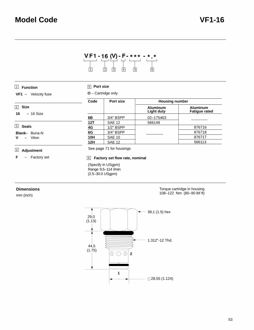
53
Model Code VF1-16
Function
VF1 – Velocity fuse
Size
16 – 16 Size
Seals
Blank– Buna-NV – Viton
Adjustment
F – Factory set
29,0(1.13)
2
1
6
2 3 4 651
1
2
3
5
Factory set flow rate, nominal
(Specify in USgpm)Range 9,5–114 l/min (2.5–30.0 USgpm)
28,55 (1.124)
1.312″-12 Thd.
38,1 (1.5) hex
44,5(1.75)
∅
Dimensionsmm (inch)
.
Port size
O – Cartridge only
6B 3/4” BSPP 12T SAE 12 4G 1/2” BSPP6G 3/4” BSPP10H SAE 1012H SAE 12
Housing number
Aluminum
02–175463566149
Light duty
Code Port size
AluminumFatigue rated
Torque cartridge in housing108–122 Nm (80–90 lbf ft)
876716876718876717566113
4 See page 71 for housings

54
VF1-20 Velocity fuse
Sectional View
DescriptionThe VF1-20-F is a factory-set, screw-in cartridge velocity fuse.
OperationThis valve is normally open from port 1 to port 2. When flow exceeds the settingof the valve, it closes. The valve returns to the open condition when the pressureat port 1 is reduced to less than 80 psi.
Ratings and specificationsPerformance data is typical with fluid at 21,8 cSt (105 SUS) and 49�C (120�F)
Typical application pressure (all ports) 210 bar (3000 psi). . . . . . . . . . . . . . . . . . . . . . . Cartridge fatigue pressure (infinite life) 210 bar (3000 psi). . . . . . . . . . . . . . . . . . . . . . . Rated flow 227 l/min (60 USgpm). . . . . . . . . . . . . . . . . . . . . . . . . . . . . . . . . . . . . . . . . . . .
Flow regulation accuracy 60–227 l/min (15–60 USgpm) � 20%. . . . . . . . . . . . . . . . . . Internal leakage Port 1 to 2 closed; <5 drops/min. . . . . . . . . . . . . . . . . . . . . . . . . . . . . . . .
maximum @ 210 bar (3000 psi)
Temperature range –40� to 120�C (–40� to 248�F). . . . . . . . . . . . . . . . . . . . . . . . . . .
Cavity C–20–2 (See page 68). . . . . . . . . . . . . . . . . . . . . . . . . . . . . . . . . . . . . . . . . . . . . . .
Fluids All general purpose hydraulic fluids such as:. . . . . . . . . . . . . . . . . . . . . . . . . . . . . MIL–H–5606, SAE 10, SAE 20, etc.
Filtration Cleanliness code 18/16/13. . . . . . . . . . . . . . . . . . . . . . . . . . . . . . . . . . . . . . . . . . Standard housing materials Aluminum. . . . . . . . . . . . . . . . . . . . . . . . . . . . . . . . . . . . . . . . Weight cartridge only 0,82 kg (1.80 lbs.). . . . . . . . . . . . . . . . . . . . . . . . . . . . . . . . . . . . . . .
Seal kits 889615 Buna-N. . . . . . . . . . . . . . . . . . . . . . . . . . . . . . . . . . . . . . . . . . . . . . . . . . . 889619 Viton
Viton is a registered trademark of E.I. DuPont
Typical Flow Regulation
Functional Symbol
2
1
Fusingdirection
Reverseflow direction
300
250
200
150
100
50
0 3 10 14 17 20
0 45 100 150 200 250
80
60
40
20
0
Pressure Drop psi
Pressure Drop bar
2
1
Cartridge Only
A
B
C
Port 1 to 2, fusing directionPort 2 to 1, reverse flow down to 0
Port 1 to 2, fusing directionPort 2 to 1, reverse flow down to 0
Port 1 to 2, fusing directionPort 2 to 1, reverse flow down to 0
A -228 l/min (60 USgpm) maximum flow setting
B -114 l/min. (30 USgpm) maximum flow setting
C -38 l/min. (10 USgpm) maximum flow setting300
7
Flo
w in
lpm
(21,
8 cS
t oil
@ 4
9 C
)
°
Flo
w in
US
gp
m(1
05 S
US
oil
@ 1
20 F
)
°

55
Model Code VF1-20
Function
VF1– Velocity fuse
Size
20 – 20 Size
Seals
Blank– Buna-NV – Viton
Adjustment
F – Factory set
38,1(1.50)
2
1
6
2 3 4 651
1
2
3
4
5
Factory set flow rate, nominal
(Specify in USgpm)Range 60–227 l/min (15–60.0 USgpm)
∅ 36,47 (1.436)
1.625″-12 Thd.
47,6 (1.87) hex
57,2(2.25)
Dimensionsmm (inch)
.
Port size
O – Cartridge only
8B 1” BSPP 16T SAE 16 6G 3/4” BSPP8G 1” BSPP12H SAE 1216H SAE 16
Housing number
Aluminum
02–175464566409
Light duty
Code Port size
AluminumFatigue rated
Torque cartridge in housing128–155 Nm (95–115 lbf ft)
876732876734876733876735
See page 71 for housings

56
FDC1-10 Flow divider/combiner
Sectional View
DescriptionThe FDC1-10 is a pressure compensated, spool type, screw-in, flowdivider/combiner cartridge.
OperationThis valve is used in the dividing mode. It will take the inlet flow (port 3) and splitthe flow according to the ratio specified, regardless of system pressure to ports 2and 4.In the combining mode this valve will take the inlet flows from ports 2 and 4 andcombine them into port 3 according to the ratio specified.
Ratings and specificationsPerformance data is typical with fluid at 21,8 cSt (105 SUS) and 49�C (120�F)
Typical application pressure (all ports) 210 bar (3000 psi). . . . . . . . . . . . . . . . . . . . . . . Cartridge fatigue pressure (infinite life) 210 bar (3000 psi). . . . . . . . . . . . . . . . . . . . . . . Rated inlet flow See model code, item. . . . . . . . . . . . . . . . . . . . . . . . . . . . . . . . . . . . .
Temperature range –40� to 120�C (–40� to 248�F). . . . . . . . . . . . . . . . . . . . . . . . . . . .
Cavity C–10–4 (See page 70). . . . . . . . . . . . . . . . . . . . . . . . . . . . . . . . . . . . . . . . . . . . . . .
Fluids All general purpose hydraulic fluids such as:. . . . . . . . . . . . . . . . . . . . . . . . . . . . . MIL–H–5606, SAE 10, SAE 20, etc.
Filtration Cleanliness code 18/16/13. . . . . . . . . . . . . . . . . . . . . . . . . . . . . . . . . . . . . . . . . . Standard housing materials Aluminum. . . . . . . . . . . . . . . . . . . . . . . . . . . . . . . . . . . . . . . . Weight cartridge only 0,10 kg (0.22 lbs.). . . . . . . . . . . . . . . . . . . . . . . . . . . . . . . . . . . . . . .
Seal kits 889625 Buna-N. . . . . . . . . . . . . . . . . . . . . . . . . . . . . . . . . . . . . . . . . . . . . . . . . . . 566080 Viton
Viton is a registered trademark of E.I. DuPont
Typical Flow Regulation
Functional Symbol
4
3
2
Cartridge Only
A -33 spoolB -44 spoolC -66 spoolD -88 spool
4
3
2
Flow Division
NOTE:Port 1 unused, blocked by blind cavity
5
Flow in USgpm (105 SUS oil @ 120°F)
800
700
600
500
400
300
200
100
00 1 2 3 4 5 6 7 8 9 10 11 12 13 14 15 16 17 18 19
A B
C D
Pre
ssu
re D
rop
psi
Pre
ssu
re D
rop
bar
Flow in lpm (21,8 cSt oil @ 49°C)
10
20
30
40
50
15 30 45 60

57
Model Code FDC1-10
Function
FDC1 – Flow divider/combiner
Size
10 – 10 Size
Seals
Blank– Buna-NV – Viton
Port Size
0 – Cartridge only
∅ 17,40 (0.685)
8,0(0.31)
2 3 4 51
1
2
3
4
5 Flow divisions (ratios)
63,9(2.51)
0.875″-14 Thd.
25,4 (1.00) hex
∅ 15,80 (0.622)
∅ 18,97 (0.747)
4
3
2
Dimensionsmm (inch)
NOTEPort 1, unused,
blocked by blind cavity
Torque cartridge in housing47–54 Nm (35–40 lbf ft)
See page 73 for housings
Code Flow Division % Max. Inlet FlowPort 4 Port 2 l/min (USgpm)
5.1 33 67 5,7 (1.5)5.5 50 50 3,8 (1)11 50 50 7,6 (2)21 67 33 11,4 (3)22 50 50 15,2 (4)33 50 50 22,8 (6)34 43 57 26,6 (7)36 33 67 34,2 (9)43 57 43 26,6 (7)44 50 50 30,4 (8)46 40 60 38,0 (10)62 75 25 30,4 (8)63 67 33 34,2 (9)64 60 40 38,0 (10)66 50 50 45,6 (12)88 50 50 60,8 (16)
3/8” BSPP SAE 6 1/4” BSPP3/8”BSPPSAE 6SAE 8
Housing numberAluminum
02–17546756623402-18580402-18580502-18580202-185803
Code Port size
3B6T2G3G6H8H
NOTE: Minimum inlet flow should not be less than 1/4 of
maximum inlet flow for a given code

58
FDC1-16 Flow divider/combiner
Sectional View
DescriptionThe FDC1-16 is a pressure compensated, spool type, screw-in, flowdivider/combiner cartridge.
OperationThis valve is used in the dividing mode. It will take the inlet flow (port 3) and splitthe flow according to the ratio specified, regardless of system pressure to ports 2and 4.In the combining mode this valve will take the inlet flows from ports 2 and 4 andcombine them into port 3 according to the ratio specified.
Ratings and specificationsPerformance data is typical with fluid at 21,8 cSt (105 SUS) and 49�C (120�F)
Typical application pressure (all ports) 210 bar (3000 psi). . . . . . . . . . . . . . . . . . . . . . . Cartridge fatigue pressure (infinite life) 210 bar (3000 psi). . . . . . . . . . . . . . . . . . . . . . . Rated inlet flow See model code, item. . . . . . . . . . . . . . . . . . . . . . . . . . . . . . . . . . . . .
Temperature range –40� to 120�C (–40� to 248�F). . . . . . . . . . . . . . . . . . . . . . . . . . . .
Cavity C–16–4 (See page 70). . . . . . . . . . . . . . . . . . . . . . . . . . . . . . . . . . . . . . . . . . . . . . .
Fluids All general purpose hydraulic fluids such as:. . . . . . . . . . . . . . . . . . . . . . . . . . . . . MIL–H–5606, SAE 10, SAE 20, etc.
Filtration Cleanliness code 18/16/13. . . . . . . . . . . . . . . . . . . . . . . . . . . . . . . . . . . . . . . . . . Standard housing materials Aluminum. . . . . . . . . . . . . . . . . . . . . . . . . . . . . . . . . . . . . . . . Weight cartridge only 0,35 kg (0.78 lbs.). . . . . . . . . . . . . . . . . . . . . . . . . . . . . . . . . . . . . . .
Seal kits 889634 Buna-N. . . . . . . . . . . . . . . . . . . . . . . . . . . . . . . . . . . . . . . . . . . . . . . . . . . 889638 Viton
Viton is a registered trademark of E.I. DuPont
Typical Flow Regulation
Functional Symbol
4
3
2
Cartridge Only
A -22 spoolB -33 spoolC -44 spoolD -55 spoolE -66 spoolF -88 spool
4
3
2
Flow Division
NOTE:Port 1 unused, blocked by blind cavity
5
Flow in USgpm (105 SUS oil @ 120°F)
Pre
ssu
re D
rop
psi
Pre
ssu
re D
rop
bar
Flow in lpm (21,8 cSt oil @ 49°C)
800
700
600
500
400
300
200
100
00 5 10 15 20 25 30 35 40 45 50
A B C D
E
F
10
20
30
40
50
50 100 150 200

59
Model Code FDC1-16
Function
FDC1 – Flow divider/combiner
Size
16 – 16 Size
Seals
Blank– Buna-NV– Viton
Port Size
0 – Cartridge only
2 3 4 51
1
2
3
4
5 Flow divisions (ratios)
104,8(4.12)
1.312″-12 Thd.
38,1 (1.50) hex
∅ 25,37 (0.999)
∅ 26,95 (1.061)
∅ 28,55 (1.124)
13,0(0.51)
4
3
2
Dimensionsmm (inch)
NOTEPort 1, unused,
blocked by blind cavity
Torque cartridge in housing108–122 Nm (80–90 lbf ft)
Code Flow Division % Max. Inlet FlowPort 4 Port 2 l/min (USgpm)
22 50 50 45,6 (12)28 20 80 114,0 (30)33 50 50 68,0 (18)36 33 67 98,0 (26)43 57 43 79,0 (21)44 50 50 90,0 (24)46 40 60 114,0 (30)55 50 50 114,0 (30)62 75 25 90,0 (24)63 67 33 98,0 (26)64 60 40 114,0 (30)66 50 50 132,0 (35)82 80 20 114,0 (30)84 67 33 132,0 (35)88 50 50 178,0 (47)
SAE 12 3/4” BSPP
Housing number
Aluminum
56620002-175468
Light duty
Code Port size
12T6B
NOTE: Minimum inlet flow should not be less than 1/4 of
maximum inlet flow for a given codeSee page 73 for housings

60
FDC1-20 Flow divider/combiner
Sectional View
DescriptionThe FDC1-20 is a line mounted, pressure compensated, spool type, flowdivider/combiner valve.
OperationThis valve is used in the dividing mode. It will take the inlet flow (port 1) and splitthe flow according to the ratio specified, regardless of system pressure to ports 2and 4.In the combining mode this valve will take the inlet flows from ports 2 and 3 andcombine them into port 1 according to the ratio specified.
Ratings and specificationsPerformance data is typical with fluid at 21,8 cSt (105 SUS) and 49�C (120�F)
Typical application pressure (all ports) 210 bar (3000 psi). . . . . . . . . . . . . . . . . . . . . . . Cartridge fatigue pressure (infinite life) 210 bar (3000 psi). . . . . . . . . . . . . . . . . . . . . . . Rated inlet flow See model code, item. . . . . . . . . . . . . . . . . . . . . . . . . . . . . . . . . . . . .
Fluids All general purpose hydraulic fluids such as:. . . . . . . . . . . . . . . . . . . . . . . . . . . . . MIL–H–5606, SAE 10, SAE 20, etc.
Filtration Cleanliness code 18/16/13. . . . . . . . . . . . . . . . . . . . . . . . . . . . . . . . . . . . . . . . . . Standard housing materials Aluminum. . . . . . . . . . . . . . . . . . . . . . . . . . . . . . . . . . . . . . . . Weight cartridge only 2,6 kg (5.75 lbs.). . . . . . . . . . . . . . . . . . . . . . . . . . . . . . . . . . . . . . . .
Seal kits 889639 Buna-N. . . . . . . . . . . . . . . . . . . . . . . . . . . . . . . . . . . . . . . . . . . . . . . . . . . 889643 Viton
Viton is a registered trademark of E.I. DuPont
Pressure Drop Curves
Functional Symbol
1
2 3
A -33 spoolB -44 spoolC -66 spoolD -88 spool
3
1
2
Flow Division
5
0 20 40 60 80 100
0 100 200 300
400
300
200
100
0
30
25
20
15
10
5
A
B
C
D
Inlet flow rate, port 1, in USgpm (105 SUS oil @ 120°F)
Pre
ssu
re D
rop
psi
Pre
ssu
re D
rop
bar
Inlet flow rate, port 1, in lpm (21,8 cSt oil @ 49°C)

61
Model Code FDC1-20
Function
FDC1 – Flow divider/combiner
Size
20 – 20 Size
Seals
Blank– Buna-NV– Viton
Port Size
16T – SAE 16 (light duty)20T – SAE 20 (light duty)
(Sold as a complete assembly.)
50,8(2.00)
2 3 4 51
1
2
3
4
5 Flow divisions (ratios)
178,0 (7.00)
152,4 (6.00) 12,7 (0.50)
31,7(1.25)
31,7(1.25)
31,7(1.25) 2 3
101,6(4.00)
76,2(3.00)
12,7(0.50)
104,0(4.10)
76,2(3.00)
44,4(1.75)
44,4(1.75) ∅ 10,0 (0.406 thru) (3 plcs.)
63,5(2.50)
1
Dimensionsmm (inch)
Torque cartridge in housing128–155 Nm (95–115 lbf ft)
Code Flow Division % Max. Inlet FlowPort 4 Port 2 l/min (USgpm)
33 50 50 190,0 (50)34 43 57 228,0 (60)36 33 67 266,0 (70)44 50 50 266,0 (70)46 40 60 304,0 (80)66 50 50 380,0 (100)88 50 50 380,0 (100)
NOTE: Minimum inlet flow should not be less than 1/4 of
maximum inlet flow for a given code

62
FDC3-10 Posi-traction valve
Sectional View
DescriptionThe FDC3-10 is a pressure compensated, spool type, screw-in, posi-tractioncartridge valve.
OperationThis valve is used in the dividing mode. It will take the inlet flow (port 3) and splitthe flow to ports 2 and 4.In the combining mode this valve will take the inlet flows from ports 2 and 4 andcombine them into port 3 according to the ratio specified.
Ratings and specificationsPerformance data is typical with fluid at 21,8 cSt (105 SUS) and 49�C (120�F)Typical application pressure (all ports) 210 bar (3000 psi). . . . . . . . . . . . . . . . . . . . . . .
Cartridge fatigue pressure (infinite life) 210 bar (3000 psi). . . . . . . . . . . . . . . . . . . . . . . Rated inlet flow See model code, item. . . . . . . . . . . . . . . . . . . . . . . . . . . . . . . . . . . . .
Temperature range –40� to 120�C (–40� to 248�F). . . . . . . . . . . . . . . . . . . . . . . . . . .
Cavity C–10–4 (See page 70). . . . . . . . . . . . . . . . . . . . . . . . . . . . . . . . . . . . . . . . . . . . . . . Fluids All general purpose hydraulic fluids such as:. . . . . . . . . . . . . . . . . . . . . . . . . . . . .
MIL–H–5606, SAE 10, SAE 20, etc.Filtration Cleanliness code 18/16/13. . . . . . . . . . . . . . . . . . . . . . . . . . . . . . . . . . . . . . . . . .
Standard housing materials Aluminum. . . . . . . . . . . . . . . . . . . . . . . . . . . . . . . . . . . . . . . . Weight cartridge only 0,10 kg (0.22 lbs.). . . . . . . . . . . . . . . . . . . . . . . . . . . . . . . . . . . . . . . Seal kits 889625 Buna-N. . . . . . . . . . . . . . . . . . . . . . . . . . . . . . . . . . . . . . . . . . . . . . . . . . .
566080 VitonViton is a registered trademark of E.I. DuPont
Pressure Drop Curves
Functional Symbol
4
3
2
Cartridge Only
A -33 spoolB -44 spoolC -66 spoolD -88 spool
4
3
2
Flow Division
NOTE:Port 1 unused, blocked by blind cavity
5
Inlet flow rate, port 3,in USgpm (105 SUS oil @ 120°F)
800
700
600
500
400
300
200
100
00 1 2 3 4 5 6 7 8 9 10 11 12 13 14 15 16 17 18 19 20
A B C D
Pre
ssu
re D
rop
psi
Pre
ssu
re D
rop
bar
Inlet flow rate, port 3, in lpm (21,8 cSt oil @ 49°C)
10
20
30
40
50
15 30 45 60 75

63
Model Code FDC3-10
Function
FDC3 – Posi-traction valve
Size
10 – 10 Size
Seals
Blank– Buna-NV– Viton
Port Size
O – Cartridge only
3
2 3 4 51
1
2
3
4
5 Flow divisions (ratios)
Code Flow Division % Max. Inlet FlowPort 4 Port 2 l/min (USgpm)
33 50 50 22,8 (6.0)44 50 50 30,4 (8.0)66 50 50 45,6 (12.0)88 50 50 60,8 (16.0)
63,9(2.51)
0.875″-14 Thd.
25,4 (1.00) hex
15,80 (0.622)17,40 (0.685)
18,97 (0.747)
4
2
∅∅∅
Dimensionsmm (inch)
8,0(0.31)
NOTEPort 1, unused,
blocked by blind cavity
Torque cartridge in housing47–54 Nm (35–40 lbf ft)
NOTE: Minimum inlet flow should not be less than 1/4 of
maximum inlet flow for a given code
3/8” BSPP SAE 6 1/4” BSPP3/8”BSPPSAE 6SAE 8
Housing numberAluminum
02–17546756623402-18580402-18580502-18580202-185803
Code Port size
3B6T2G3G6H8H
See page 73 for housings

64
FDC3-16 Posi-traction valve
50
DescriptionThe FDC3-16 is a pressure compensated, spool type, screw-in, posi-tractioncartridge valve.
OperationThis valve is used in the dividing mode. It will take the inlet flow (port 3) and splitthe flow to ports 2 and 4.In the combining mode this valve will take the inlet flows from ports 2 and 4 andcombine them into port 3.
Ratings and specificationsPerformance data is typical with fluid at 21,8 cSt (105 SUS) and 49�C (120�F)Typical application pressure (all ports) 210 bar (3000 psi). . . . . . . . . . . . . . . . . . . . . . .
Cartridge fatigue pressure (infinite life) 210 bar (3000 psi). . . . . . . . . . . . . . . . . . . . . . . Rated inlet flow See model code, item. . . . . . . . . . . . . . . . . . . . . . . . . . . . . . . . . . . . .
Temperature range –40� to 120�C (–40� to 248�F). . . . . . . . . . . . . . . . . . . . . . . . . . .
Cavity C–16–4 (see page 70). . . . . . . . . . . . . . . . . . . . . . . . . . . . . . . . . . . . . . . . . . . . . . . . Fluids All general purpose hydraulic fluids such as:. . . . . . . . . . . . . . . . . . . . . . . . . . . . .
MIL–H–5606, SAE 10, SAE 20, etc.Filtration Cleanliness code 18/16/13. . . . . . . . . . . . . . . . . . . . . . . . . . . . . . . . . . . . . . . . . .
Standard housing materials Aluminum. . . . . . . . . . . . . . . . . . . . . . . . . . . . . . . . . . . . . . . . Weight cartridge only 0,35 kg (0.78 lbs.). . . . . . . . . . . . . . . . . . . . . . . . . . . . . . . . . . . . . . . Seal kits 889634 Buna-N. . . . . . . . . . . . . . . . . . . . . . . . . . . . . . . . . . . . . . . . . . . . . . . . . . .
889638 VitonViton is a registered trademark of E.I. DuPont
Functional Symbol
Sectional View
4
3
2
Cartridge Only
A -22 spoolB -33 spoolC -44 spoolD -55 spoolE -66 spoolF -88 spool
4
3
2
Flow Division
NOTE:Port 1 unused, blocked by blind cavity
Pressure Drop Curves
5
800
700
600
500
400
300
200
100
00 5 10 15 20 25 30 35 40 45 50
F
Pre
ssu
re D
rop
psi
Pre
ssu
re D
rop
bar
10
20
30
40
A
B C D E
Flow in USgpm (105 SUS oil @ 120°F)
Pre
ssu
re D
rop
psi
Flow in lpm (21,8 cSt oil @ 49°C)50 100 150 200

65
Model Code FDC3-16
Function
FDC3 – Posi-traction valve
Size
16 – 16 Size
Seals
Blank– Buna-NV– Viton
Port Size
O – Cartridge only
4
3
2
2 3 4 51
1
2
3
4
5 Flow divisions (ratios)
104,8(4.13)
1.312″-12 Thd.
38,1 (1.50) hex
∅ 25,37 (0.999)∅ 26,95 (1.061)∅ 28,55 (1.124)
Dimensionsmm (inch)
13,0(0.51)
NOTEPort 1, unused,
blocked by blind cavity
Torque cartridge in housing108–122 Nm (80–90 lbf ft)
12T6B
Housing number
Aluminum
56620002–175468
Light duty
Code Port size
Code Flow Division % Max. Inlet FlowPort 4 Port 2 l/min (USgpm)
22 50 50 57,0 (15)33 50 50 76,0 (20)44 50 50 106,4 (28)55 50 50 129,2 (34)66 50 50 152,0 (40)88 50 50 228,0 (60)
SAE 123/4” BSPP
NOTE: Minimum inlet flow should not be less than 1/4 of
maximum inlet flow for a given code
See page 73 for housings

66
FDC3-20 Posi-traction valve
Sectional View
DescriptionThe FDC3-20 is a line mounted, pressure compensated, spool type, posi-tractioncartridge valve.
OperationThis valve is used in the dividing mode. It will take the inlet flow (port 1) and splitthe flow to ports 2 and 3.In the combining mode this valve will take the inlet flows from ports 2 and 3 andcombine them into port 1 according to the ratio specified.
Ratings and specificationsPerformance data is typical with fluid at 21,8 cSt (105 SUS) and 49�C (120�F)Typical application pressure (all ports) 210 bar (3000 psi). . . . . . . . . . . . . . . . . . . . . . .
Cartridge fatigue pressure (infinite life) 210 bar (3000 psi). . . . . . . . . . . . . . . . . . . . . . . Rated inlet flow See model code, item. . . . . . . . . . . . . . . . . . . . . . . . . . . . . . . . . . . . .
Temperature range –40� to 120�C (–40� to 248�F). . . . . . . . . . . . . . . . . . . . . . . . . . . .
Fluids All general purpose hydraulic fluids such as:. . . . . . . . . . . . . . . . . . . . . . . . . . . . . MIL–H–5606, SAE 10, SAE 20, etc.
Filtration Cleanliness code 18/16/13. . . . . . . . . . . . . . . . . . . . . . . . . . . . . . . . . . . . . . . . . . Standard housing materials Aluminum. . . . . . . . . . . . . . . . . . . . . . . . . . . . . . . . . . . . . . . .
Weigh cartridge only 2,6 kg (5.75 lbs.). . . . . . . . . . . . . . . . . . . . . . . . . . . . . . . . . . . . . . . . Seal kits (2 req’d.) 889639 Buna-N. . . . . . . . . . . . . . . . . . . . . . . . . . . . . . . . . . . . . . . . . .
889643 VitonViton is a registered trademark of E.I. DuPont
Functional Symbol
1
2 3
Pressure Drop CurvesCartridge Only
A -33 spoolB -44 spoolC -66 spoolD -88 spool
3
1
2
Flow Division
5
Inlet flow rate, port 1, in USgpm (105 SUS oil @ 120°F)
Inlet flow rate, port 1, in lpm (21,8 cSt oil @ 49°C)
30
25
20
15
10
5
400350
300250200150100
50
0
0 100 200 300 400 500 600
0 20 40 60 80 100 120 140
Pre
ssu
re D
rop
psi
Pre
ssu
re D
rop
barA
BC D

67
Model Code FDC3-20
Function
FDC3 – Posi-traction valve
Size
20 – 20 Size
Seals
Blank– Buna-NV – Viton
Port Size
16T – SAE 16 (light duty)20T – SAE 20 (light duty)(Sold as complete assembly.)
44,4(1.75)
2 3 4 51
1
2
3
4
5 Flow divisions (ratios)
Code Flow Division % Max. Inlet FlowPort 2 Port 3 l/min (USgpm)
33 50 50 190,0 (50.0)44 50 50 266,0 (70.0)66 50 50 380,0 (100.0)88 50 50 570,0 (150.0)
152,4 (6.00)
76,2(3.0)
31,7(1.25)
63,5(2.50)
31,7 (1.25) 31,7 (1.25)
2 3
12,7(0.50)
76,2(3.00)
101,6(4.00)
76,2(3.00)
44,4(1.75)
104,0(4.10)
12,7 (0.50)12,7 (0.50)
∅ 10,3 (0.406 thru) (3 plcs.)1
Dimensionsmm (inch)
Torque cartridge in housing128–155 Nm (95–115 lbf ft)
NOTE: Minimum inlet flow should not be less than 1/4 of
maximum inlet flow for a given code

68
C-**-2 Cavity Dimensions
BThese diameters
These diameters A
unless otherwise specified.
unless otherwise specified.
Dimensionsmm (inch)
Cavity bores can be machinedaccurately in aluminum or steel.The necessary UNF, or UNthreads may be machined usingstandard small tools, possiblyalready in your machine shop orfrom a local tool supplier. For indepth advice on the machiningof cavities, consult your Vickerssales specialist.
Either you, our customer, orVickers can design andmanufacture customizedmanifolds or housings dedicatedto individual applications. We callthe resulting valve packagesModular Circuit Designs (MCDs).Cartridges selected for yourapplication can beaccommodated in one or moreMCDs, according to yourrequirements.
0,7938(0.031)
–B–
–A–
46
H
1,57(0.062)
RDia
X
G
J
Emin.
0,190 ± 0.06350.0075 ± 0.0025
46
C
AD
Y
Z
P 45�F
2-way cavity
15�
1,588(0.0625)
W
2–way cavitywith undercut (U)
29�
B
29�
R
0,025 mm (.001 inch)
0,051 mm (.002 inch)
C +0,051 0( +0.002 0)
B +0,051 0( +0.002 0)
19,05(0.750)
3,30/3,68(0.130/0.145)
12,70(0.500)
22,22(0.875)
12,70(0.500)
2,54/2,92(0.100/0.115)
Y Z
34,29(1.350)
14,29(0.562)
11,11(0.438)
RMax.Dia.
3,30/3,68(0.130/0.145)
24,76(0.975)
57,66(2.270)
30,16(1.188)
33,32(1.312)
18,23(0.718)
C–12–2 (U)38,10
(1.500)
30,16(1.188)
44,45(1.750)
20,65(0.813)
17,47(0.688)
.750”–16 12,70(0.500)
2,54/2,92(0.100/0.115)
19,05(0.750)
12,72(0.501)
14,68(0.578)
30,17(1.188)
EFull
Thread
A Spotface
DThread
F G J P
C–10–2
C–16–2
C–20–2
29,15(1.148)
1.062”-12 22,22(0.875)
34,92(1.375)
23,82(0.938)
27,94(1.100)
46,35(1.825)
C–8–2
24,00(0.945)
20,62(0.812)
.875”–14 15,88(0.625)
23,81(0.937)
15,90(0.626)
44,45(1.750)
35,58(1.401)
31,34(1.234) 1.312”–12 22,22
(0.875)34,14
(1.344)28,62
(1.127)46,84
(1.844)24,60
(0.968)
30,96(1.218)
58,72(2.312)
36,55(1.439)
3,35/3,73(0.132/0.147)
20,64(0.812)1.625”–1239,12
(1.540)43,59
(1.716)
W
30,83(1.214)
8,74(0.344)
11,11(0.437)
19,05(0.750)
25,40(1.000)
XMax.Dia.
30,16(1.188)
C–12–2U(only)
Cavitymm (inch)
Cavitymm (inch)
H�0,0254(�0.001)

69
C-**-3 Cavity Dimensions
3-way cavity
S G
F
L
0,8 (0.03)
29�
X
15�
A
B
C
H
K
D
45�
1,575(0.062)
R
46
46
–A–
0,190 ± 0.06350,0075 ± 0.0025–B–
R Dia.
T Dia
1,575(0.062)
1,575(0.062)
Emin.
R
R
46
BThese diameters
These diameters A
unless otherwise specified.
unless otherwise specified.
Dimensionsmm (inch)
R
P
J
0,025 mm (.001 inch)
0,051 mm (.002 inch)
B +0,051 0( +0.002 0)
TMax. Dia.
K�0,0254( �0.001)
47,62(1.875)
43,25(1.703)
75,39(2.968)
100,02(3.938)
69,21(2.725)
3,30/3,68 (0.130/0.145)
22,22(0.875)
22,25(0.876)
2,54/2,92(0.100/0.115)
38,10(1.500)
21,59(0.850)
20,62(0.812)
24,00(0.945)
30,16(1.188)30,16
(1.188)
20,65(0.813)
17,47(0.688) 0.750”–16 12,70
(0.500)2,54/2,92
(0.100/0.115)18,23
(0.718)15,90
(0.626)14,30
(0.563)33,25
(1.270)
EFull
Thread
Cavitymm (inch)
A Spotface
DThread
F G J
C–10–3
C–8–3
0.875”–14 15,87(0.625)
17,50(0.689)
15,90(0.626)
L
XMax. Dia.
14,68(0.578)
18,26(0.719)
6,35(0.250)
SRMax. Dia.
5,94(0.234)
6,35(0.250)
5,94(0.234)
14,27(0.562)
P
28,98(1.141)
12,70(0.500)
34,13(1.344)
C–10–3
C–8–3
Cavitymm (inch)
C–16–3
C–20–3
C–16–3
C–20–3
44,45(1.750)
35,58(1.401)
31,34 (1.234) 1.312”-12 34,13
(1.344) 28,62 (1.127)
62,71 (2.469)
27,02(1.064)
43,59(1.716)
57,66(2.270)
39,12(1.540) 1.625”-12 20,64
(0.812) 3,35/3,73 (0.132/0.147)
44,45(1.750)
36,55(1.439)
85,72(3.375)
33,38(1.314)
24,60(0.969)
15,88(0.625)
53,18(2.093)
15,88(0.625)
19,05(0.750)
30,96(1.218)
25,40(1.000)
71,44(2.812)
30,16(1.188)
25,40(1.000)
C–12–3
C–12–3
38,10(1.500) 1.062’’–12 22,22
(0.875) 3,30/3,68 (0.130/0.145)
34,92(1.375)
23,82(0.938)
57,78(2.275)
27,94(1.100)
12,70(0.500)
50,80(2.000)
12,70(0.500)
20,62(0.812)
29,15(1.148)
24,76(0.975)
H�0,0254( �0.001)
C +0,051 0( +0.002 0)

70
C-**-4 Cavity Dimensions
4-Way Cavity
0.0100.005
R
4646
46
45�
46
1,575 R(0.062)
–A–
0,79 (0.031)
29�
15�
A
B
C
H
P
J
U
N
V Dia.
M
K
X
T Dia.
L
S
G
F
R DIa.
E
D
BThese diameters
These diameters A
unless otherwise specified.
unless otherwise specified.
1,6 R(0.062)
Dimensionsmm (inch)
–B–
0,025 mm (.001 inch)
0,051 mm (.002 inch)
50,00(1.968)
53,98(2.125)
TMax. Dia.
SRMax. Dia.
XMax. Dia.
L P
15,90(0.626)
VUN
63,50(2.500)
18,26(0.718)
6,35(0.250)
34,13(1.343)
6,35(0.250)
14,29(0.562)
6,35(0.250)
91,29(3.594)
25,45(1.002)
103,99(4.094)
24,60(0.968)
15,88(0.625)
53,18(2.093)
15,87(0.625)
81,76(3.218)
15,88(0.625)
19,05(0.750)
Cavitymm (inch)
C-10-4
C-16-4
M�0,0254(�0.001)
C +0,051 0( +0.002 0)
B +0,051 0( +0.002 0)
C-16-444,45
(1.750)31,34
(1.234)35,58
(1.401) 1.312”-1222,22
(0.875)3,30/3,68
(0.130/0.145)34,14
(1.344)28,62
(1.127)62,71
(2.469)27,02
(1.064)
19,08(0.751)
30,16(1.188)
24,00(0.945)
EFull Thread
Cavitymm (inch)
ASpotface
DThread
F G J
C-10-438,10
(1.500)20,62
(0.812)15,88
(0.625)2,54/2,92
(0.100/0.115)22,22
(0.875)17,50
(0.689)0.875”–14
H�0,0254(�0.001)
K�0,0254(�0.001)

71
C-**- 2 Aluminum Housings
Housing Ports 1 & 2 Part Number
C-10-2Light
3/8” BSPP 02-175462LightDuty SAE 6 566151
C-16-2Light
3/4” BSPP 02-175463LightDuty SAE 12 566149
C-20-2Light
1” BSPP 02-175464LightDuty SAE 16 566409
Note: BSPP porting is designated by either ‘‘B’’ or ‘‘G’’ in the model codeSAE porting is designated by either ‘‘H’’ or‘‘T’’ in the model code
Housing Ports 1 & 2 Part Number
1/4” BSPP 02–160727
C-8-2 3/8” BSPP 02–160728C-8-2FatigueR t d
SAE 4 02–160730gRated SAE 6 02–160731
SAE 8 02–160732
1/4” BSPP 876702C-10-2F tig e
3/8” BSPP 876703FatigueRated SAE 6 876700Rated
SAE 8 876701
1/2” BSPP 02–161116C-12-2UF tig e
3/4” BSPP 02–161115FatigueRated SAE 10 02–160641Rated
SAE 12 02–160645
1/2” BSPP 02–161118C-12-2F tig e
3/4” BSPP 02–161117FatigueRated SAE 10 02–160640Rated
SAE 12 02–160644
1/2” BSPP 876716C-16-2F tig e
3/4” BSPP 876718FatigueRated SAE 10 876717Rated
SAE 12 566113
3/4” BSPP 876732C-20-2F tig e
1” BSPP 876734FatigueRated SAE 12 876733Rated
SAE 16 876735
C
A
B
G
H
D
E
F
1
2
C
A
G
F
1
2
H
All exceptC-12-2(U)
C-12-2(U)
B
I
E
D
I
F
Cavity mm (inch) A B C D E F G H I Mass kg (lb.)
C-10-2Light Duty
50,8(2.00)
19,0(0.75)
50,8(2.00)
31,7(1.25)
15,9(0.62)
19,0(0.75)
7,1(0.28)
3,1(0.12)
12,7(0.50)
0,1(0.35)
C-16-2Light Duty
76,2(3.0)
28,5(1.12)
76,2(3.00)
47,6(1.87)
23,8(0.94)
25,4(1.00)
8,6(0.34)
4,0(0.16)
19,0(0.75)
0,5(1.21)
C-20-2Light Duty
88,9(3.5)
34,3(1.35)
88,9(3.50)
68,5(2.70)
34,3(1.35)
36,8(1.45)
8,6(0.34)
4,0(0.16)
21,6(0.85)
0,8(1.90)
C-8-2Fatigue Rated
50,8(2.00)
19,0(0.75)
51,0(2.00)
38,1(1.50)
19,0(0.75)
3,4(0.13)
15,5(0.61)
7,1(0.28)
12,7(0.50)
0,2(0.46)
C-10-2Fatigue Rated
63,5(2.50)
25,4(1.00)
63,5(2.50)
50,8(2.00)
25,4(1.00)
9,5(0.37)
20,8(0.81)
7,1(0.28)
19,0(0.75)
0,4(1.00)
C-12-2(U)Fatigue Rated
88,9(3.50)
44,5(1.75)
88,9(3.50)
50,8(2.00)
25,4(1.00)
12,7(0.50)
28,7(1.13)
63,5(2.50)
63,5(2.50)
0,8(1.96)
C-16-2Fatigue Rated
88,9(3.50)
34,9(1.37)
88,9(3.50)
63,5(2.50)
31,7(1.25)
10,3(0.40)
28,4(1.11)
8,7(0.34)
25,4(1.00)
1,2(2.75)
C-20-2Fatigue Rated
101,6(4.00)
38,1(1.50)
101,6(4.00)
82,5(3.25)
41,3(1.62)
10,3(0.40)
36,0(1.41)
8,7(0.34)
25,4(1.00)
1,8(4.00)

J
C
B
H
G
A
D
E
F
1
2
3
I
F
72
C-**-3 Aluminum Housings
Housing Ports 1, 2 & 3 Part Number
C-10-3Light D ty
SAE 6 566162Light Duty
3/8” BSPP 02–173358
C-16-3 3/4” BSPP 02–175465C 16 3Light Duty SAE 12 566152
C 8 31/4” BSPP 02–160739
C-8-3F tig e
3/8” BSPP 02–160740FatigueRated SAE 4 02–160741Rated
SAE 6 02–160742
C 10 31/4” BSPP 876705
C-10-3F tig e
3/8” BSPP 876714FatigueRated SAE 6 876704Rated
SAE 8 876711
C 16 31/2” BSPP 876720
C-16-3F tig e
3/4” BSPP 876722FatigueRated SAE 10 876721Rated
SAE 12 876723Note: BSPP porting is designated by either ‘‘B’’
or ‘‘G’’ in the model codeSAE porting is designated by either ‘‘H’’ or‘‘T’’ in the model code
Cavitymm (inch)
A B C D E F G H I J Masskg (lb.)
C-10-3Light Duty
63,5(2.50)
31,7(1.25)
66,6(2.62)
31,7(1.25)
15,8(0.62)
3,1(0.12)
19,0(0.75)
34,9(1.37)
7,1(0.28)
12,7(0.50)
0,3(0.64)
C-16-3Light Duty
101,6(4.00)
50,8(2.00)
107,9(4.25)
50,8(2.00)
25,4(1.00)
4,0(0.16)
25,4(1.00)
53.9(2.12)
8,6(0.33)
25,4(1.00)
1,0(2.3)
C-8-3Fatigue Rated
63,5(2.50)
31,8(1.25)
66,6(2.62)
38,1(1.50)
19,0(0.75)
3,4(0.13)
15,5(0.61)
29,8(1.17)
7,1(0.28)
13,0(0.51)
0,4(0.83)
C-10-3Fatigue Rated
76,2(3.00)
38,1(1.50)
76,2(3.00)
50,8(2.00)
25,4(1.00)
9,5(0.37)
20,8(0.81)
36,6(1.44)
7,1(0.28)
19,0(0.75)
0,7(1.65)
C-16-3Fatigue Rated
114,3(4.50)
60,3(2.37)
114,3(4.50)
63,5(2.50)
31,7(1.25)
10,3(0.40)
28,4(1.12)
57,0(2.24)
8,7(0.34)
25,4(1.00)
2,0(4.50)

H
B
J
A
C
G
D
F
E
2
3
4K
I
F
73
C-**-4 Aluminum Housings (FDC1 & FDC3 only)
Housing Ports 1, 2, 3 & 4 Part Number
C-10-4 3/8” BSPP 02–175467C 10 4Light Duty SAE 6 566234
C-16-4 3/4” BSPP 02-175468C 16 4Light Duty SAE 12 566200
1/4” BSPP 02-185804C–10–4F tig e
3/8” BSPP 02-185805FatigueRated SAE 6 02-185802Rated
SAE 8 02-185803Note: BSPP porting is designated by ‘‘B’’
in the model codeSAE porting is designated by ‘‘T’’ in the model code
Cavitymm (inch)
A B C D E F G H I J K Masskg (lb.)
C-10-4Light Duty
63,5(2.50)
31,7(1.25)
82,5(3.25)
31,7(1.25)
15,8(0.62)
3,1(0.12)
34,9(1.37)
19,0(0.75)
7,1(0.28)
9,5(0.37)
50,8(2.00)
0,3(0.72)
C-16-4Light Duty
101,6(4.00)
50,8(2.00)
133,3(5.25)
50,8(2.00)
25,4(1.00)
3,8(0.15)
53,9(2.12)
25,4(1.00)
8,7(0.34)
22,2(0.87)
82,5(3.25)
1,4(3.24)
C-10-4Fatigue Rated
76,2(3.00)
38,1(1.50)
88,9(3.50)
50,8(2.00)
25,4(1.00)
9,5(0.37)
36,6(1.44)
20,8(0.82)
7,1(0.28)
12,7(0.50)
52,5(2.07)
0,9(2.00)

D
E
H J∅
F
I
1
2
A
CG
NOTE8 series utilize slot in
place of mounting hole
C
A
F
H
1
2
I
C–12–2(U)
B
E
D
I
B
G
74
C-**-2 Steel Housings
Housing Ports 1 & 2 Part Number
1/4” BSPP 02-160733
3/8” BSPP 02-160734
C–8–2 SAE 4 02-160736
SAE 6 02-160737
SAE 8 02-160738
1/4” BSPP 02-175102
C–10–23/8” BSPP 02-175103
C–10–2SAE 6 02-175100
SAE 8 02-175101
1/2” BSPP 02-172512
C–12–2U3/4” BSPP 02-162922
C–12–2USAE 10 02-169817
SAE 12 02-169790
1/2” BSPP 02-172062
C–12–23/4” BSPP 02-169665
C–12–2SAE 10 02-169744
SAE 12 02-169782
1/2” BSPP 02-175106
C–16–23/4” BSPP 02-175107
C–16–2SAE 10 02-175104
SAE 12 02-175105
Note: BSPP porting is designated by ‘‘G’’ in the model codeSAE porting is designated by ‘T’’ in the model code
Cavitymm (inch)
A B C D E F G H I J Masskg (lb.)
C-8-2 50,8(2.00)
19,0(0.75)
50,8(2.00)
38,1(1.50)
19,0(0.75)
15,5(0.61)
38,1(1.50)
3,3(0.13)
43,9(1.73)
7,1(0.28)
0,5(1.19)
C-10-2 63,5(2.50)
25,4(1.00)
63,5(2.50)
44,4(1.75)
22,2(0.87)
19,0(0.75)
50,8(2.00)
9,5(0.37)
44,4(1.75)
7,1(0.28)
0,3(0.83)
C-12-2(U) 88,9(3.50)
28,5(1.12)
88,9(3.50)
50,8(2.00)
25,4(1.00)
28,7(1.13)
76,2(3.00)
12,7(0.50)
63,5(2.50)
10,3(0.40)
1,9(4.28)
C-16-2 88,9(3.50)
38,1(1.50)
76,2(3.00)
50,8(2.00)
25,4(1.00)
25,4(1.00)
63,5(2.50)
12,7(0.50)
63,5(2.50)
10,3(0.40)
2,2(5.00)

75
C-**-3 Steel Housings
Housing Ports 1, 2 & 3 Part Number
1/4” BSPP 02-160743
C-8-33/8” BSPP 02-160746
C-8-3SAE 4 02-160745
SAE 6 02-160744
1/4” BSPP 02-175127
C–10–33/8” BSPP 02-175128
C–10–3SAE 6 02-175124
SAE 8 02-175125
Note: BSPP porting is designated by ‘‘G’’ in the model codeSAE porting is designated by ‘T’’ in the model code
Cavitymm (inch)
A B C D E F G H I J K Masskg (lb.)
C-8-3 63,5(2.50)
31,8(1.25)
66,0(2.75)
38,1(1.50)
19,0(0.75)
15,5(0.61)
53,0(2.12)
3,3(0.13)
56,6(2.23)
7,1(0.28)
29,8(1.17)
0,9(2.15)
C-10-3 76,2(3.00)
38,1(1.50)
76,2(3.00)
44,4(1.75)
22,2(0.87)
19,0(0.75)
63,5(2.50)
9,5(0.37)
57,1(2.25)
7,1(0.28)
34,9(1.37)
1,7(3.75)
B
D
E
H J∅I
F
G
1
2
3C
A
K
NOTE8 series utilize slot in
place of mounting hole

76
Supporting Products
Roughing Tools Roughers are basically step drills which leave .030” per cutting diameter and .015” above all radii for the finishing reamer, with anadditional .015” depth in the cavity bottom as clearance. The roughing tool is necessary to prepare the cavity for the finishing reamer,which has not been designed for the primary forming or bottom cutting.We offer two types of roughers, one for aluminum and one for steel. The aluminum rougher is manufactured with a 4 facet point andpolished flutes. The steel rougher is supplied with a standard drill point. Both types will work in either material, however, longevity of analuminum tool will be sacrificed when used continually in steel.
Cavity Material Model Code AssemblyNumber
Cavity Material Model Code AssemblyNumber
2–Way 3–Way
C-8-2 Aluminum/Steel RT1-8-2-AS-8028 02-165580 C-8-3 Aluminum/Steel RT1-8-3-AS-8291 02-162384
C-10-2 Aluminum RT-10-2-A-8030 889509 C-10-3 Aluminum RT-10-3-A-8038 889511
C-10-2 Steel RT-10-2-S-8035 889510 C-10-3 Steel RT-10-3-S-8043 889512
C-12-2 Aluminum/Steel RT-12-2-AS-8213 02-160625 C-16-3 Aluminum RT-16-3-A-8039 565825
C-16-2 Aluminum RT-16-2-A-8031 889515 C-16-3 Steel RT-16-3-S-8044 889517
C-16-2 Steel RT-16-2-S-8036 889516 4-Way
C-20-2 Aluminum RT-20-2-A-8032 565822 C-10-4 Aluminum RT-10-4-A-8072 889513
C-20-2 Steel RT-20-2-S-8037 889519 C-10-4 Steel RT-10-4-S-8073 889514
C-16-4 Aluminum RT-16-4-A-8074 889518
C-16-4 Steel RT-16-4-S-8075 565828
Finishing Tools These finishing tools have been designed as precision reamers for finishing operations only. They are not intended for primary formingor bottom cutting operations. Vickers recommends that a finishing tool only be used in a properly roughed hole. Failure to conform to thispractice will produce unsatisfactory size and finishes and possibly break the tool.
Cavity Material Model Code AssemblyNumber
Cavity Material Model Code AssemblyNumber
2-Way3-Way
2-WayC-8-3 Aluminum/Steel FT-8-3-AS-8295 02-171292
C-8-2 Aluminum/Steel FT1-8-2-AS-8070 02-112933 C-10-3 Aluminum/Steel FT-10-3-AS-8050 565834
C-10-2 Aluminum/Steel FT-10-2-AS-8048 566235 C-16-3 Aluminum/Steel FT-16-3-AS-8080 565836
C-12-2 Aluminum/Steel FT-12-2-AS-8214 02-162162 4-Way
C-16-2 Aluminum/Steel FT-16-2-AS-8078 565832 C-10-4 Aluminum/Steel FT-10-4-AS-8052 565838
C-20-2 Aluminum/Steel FT-20-2-AS-8079 565833 C-16-4 Aluminum/Steel FT-16-4-AS-8084 566571
Finishing Form Tools Speed & Feed for Aluminum 6061-T6 (T651)CNC MACHINE TOOL BRIDGEPORT / LAGUN
TYPE MACHINES
Tool Size RPM IPM Tool Size RPM IPM
C-10-2 C-10-2
C-10-3 C-10-3 800-1000 6-5C-10-4 C-10-4
C-16-2 600 4 C-16-2
C-16-3 C-16-3250 2 1/2
C-16-3S C-16-3S250 2 1/2
C-16-4 C-16-4
This information is recommended as a goodstarting point. Speeds and/or feeds may beincreased or decreased depending on actualmachining conditions.
NOTE: Finish form tools may require 1/2 to1-1/2 second dwell to obtain necessary finish

77
Index
MODEL DESCRIPTION PAGEC**-2 Aluminum Housings 71C**-3 Aluminum Housings 72C**-4 Aluminum Housings 73C**-2 Cavity Dimensions 68C**-3 Cavity Dimensions 69C**-4 Cavity Dimensions 70C**-2 Steel Housings 74C**-3 Steel Housings 75FAR1-10 Flow regulator valve 16FAR1-12 Flow regulator valve 18
FCV6-16 Flow control valves 48FCV7-10 Flow control valves 44FCV11-12 Flow control valves 46FDC1-10 Flow divider/combiner 56FDC1-16 Flow divider/combiner 58FDC1-20 Flow divider/combiner 60FDC3-10 Posi-traction valve 62FDC3-16 Posi-traction valve 64FDC3-20 Posi-traction valve 66FR1-16-F Flow regulator valve 8FR1-20-F Flow regulator valve 10FR2-10 Flow regulator valve 12FR2-16 Flow regulator valve 14FR5-8 Flow regulator valve 4FR5-10-F Flow regulator valve 6
Introduction 2MRV2-10 Manual rotary valve 32MRV2-16 Manual rotary valve 34NV1-8 Needle valve 36NV1-10 Needle valve 38NV1-16 Needle valve 40NV1-20 Needle valve 42PFR1-16-F Priority flow regulator 26PFR2-10 Priority flow regulator 28PFR2-16 Priority flow regulator 30PFR5-8 Priority flow regulator 22PFR5-10-F Priority flow regulator, fixed 24Supporting Products Roughing tools
Finishing tools7676
VF1-10-F Velocity fuse 50VF1-16-F Velocity fuse 52VF1-20-F Velocity fuse 54
Printed in U.S.A.
78
Fluid CleanlinessThe cleanliness code for valves in thiscatalog is 18/16/13.
Proper fluid condition is essential for longand satisfactory life of hydrauliccomponents and systems. Hydraulic fluidmust have the correct balance of
Proper fluid condition is essential for longand satisfactory life of hydrauliccomponents and systems. Hydraulic fluidmust have the correct balance of
“Vickers Guide to Systemic ContaminationControl” available from your local Vickersdistributor or by contacting Vickers,Incorporated. Recommendations onfiltration and the selection of products tocontrol fluid condition are included in 561.