Vickers Proportional Valves Proportional Directional and ...
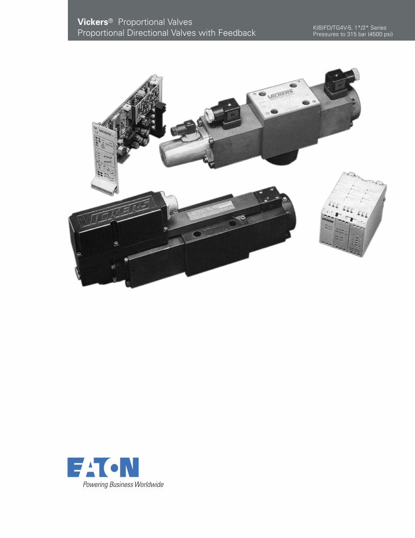
Vickers® Proportional ValvesProportional Directional Valves with Feedback
K(B)FD/TG4V-5, 1*/2* SeriesPressures to 315 bar (4500 psi)

2 EATON Vickers® Proportional Valves KBFD/TG4V-5 V-VLPO-MC008-E1 April 2009
Table of Contents
Introduction . . . . . . . . . . . . . . . . . . . . . . . . . . . . . . . . . . . . . . . . . . . . . . . . . . . . . . . . . . . . . . . . . . . . . . . . . . . . . . . . . . . . 3
Typical Section View. . . . . . . . . . . . . . . . . . . . . . . . . . . . . . . . . . . . . . . . . . . . . . . . . . . . . . . . . . . . . . . . . . . . . . . . . . . . . . 3
Model Code . . . . . . . . . . . . . . . . . . . . . . . . . . . . . . . . . . . . . . . . . . . . . . . . . . . . . . . . . . . . . . . . . . . . . . . . . . . . . . . . . . . . 4
Spool Data . . . . . . . . . . . . . . . . . . . . . . . . . . . . . . . . . . . . . . . . . . . . . . . . . . . . . . . . . . . . . . . . . . . . . . . . . . . . . . . . . . . . . 5
Fuctional Symbols . . . . . . . . . . . . . . . . . . . . . . . . . . . . . . . . . . . . . . . . . . . . . . . . . . . . . . . . . . . . . . . . . . . . . . . . . . . . . . . 5
Operating Data
Valves with Amplifier, KBFD/TG4V-5 . . . . . . . . . . . . . . . . . . . . . . . . . . . . . . . . . . . . . . . . . . . . . . . . . . . . . . . . . . . . . . . . . 6
Valves without Amplifier, KFD/TG4V-5 . . . . . . . . . . . . . . . . . . . . . . . . . . . . . . . . . . . . . . . . . . . . . . . . . . . . . . . . . . . . . . . . 7KBFD/TG4V-5 & KFD/TG4V-5 . . . . . . . . . . . . . . . . . . . . . . . . . . . . . . . . . . . . . . . . . . . . . . . . . . . . . . . . . . . . . . . . . . . . . . 7
Pressures and Flow Rates . . . . . . . . . . . . . . . . . . . . . . . . . . . . . . . . . . . . . . . . . . . . . . . . . . . . . . . . . . . . . . . . . . . . . . . . . 7
Performance Curves
Power Capacity Envelopes, Single Solenoid Models. . . . . . . . . . . . . . . . . . . . . . . . . . . . . . . . . . . . . . . . . . . . . . . . . . . . . 8Power Capacity Envelopes, Double Solenoid Models . . . . . . . . . . . . . . . . . . . . . . . . . . . . . . . . . . . . . . . . . . . . . . . . . . . . 8
Flow Gain Curves . . . . . . . . . . . . . . . . . . . . . . . . . . . . . . . . . . . . . . . . . . . . . . . . . . . . . . . . . . . . . . . . . . . . . . . . . . . . . . . . 9Frequency Response . . . . . . . . . . . . . . . . . . . . . . . . . . . . . . . . . . . . . . . . . . . . . . . . . . . . . . . . . . . . . . . . . . . . . . . . . . . . . 9
Installation Dimensions
KFDG4V-5 . . . . . . . . . . . . . . . . . . . . . . . . . . . . . . . . . . . . . . . . . . . . . . . . . . . . . . . . . . . . . . . . . . . . . . . . . . . . . . . . . . . . . 10KFTG4V-5 . . . . . . . . . . . . . . . . . . . . . . . . . . . . . . . . . . . . . . . . . . . . . . . . . . . . . . . . . . . . . . . . . . . . . . . . . . . . . . . . . . . . . 10
KBFDG4V-5. . . . . . . . . . . . . . . . . . . . . . . . . . . . . . . . . . . . . . . . . . . . . . . . . . . . . . . . . . . . . . . . . . . . . . . . . . . . . . . . . . . . 11KBFTG4V-5 . . . . . . . . . . . . . . . . . . . . . . . . . . . . . . . . . . . . . . . . . . . . . . . . . . . . . . . . . . . . . . . . . . . . . . . . . . . . . . . . . . . . 11
Subplates and Mounting Surfaces
General Description . . . . . . . . . . . . . . . . . . . . . . . . . . . . . . . . . . . . . . . . . . . . . . . . . . . . . . . . . . . . . . . . . . . . . . . . . . . . . 12Installation Dimensions, KDGSM-5-676805-2* (w/rear port L) . . . . . . . . . . . . . . . . . . . . . . . . . . . . . . . . . . . . . . . . . . . . 13Installation Dimensions, EKDGSM-01Y-1*-R (w/side port L) . . . . . . . . . . . . . . . . . . . . . . . . . . . . . . . . . . . . . . . . . . . . . . 13
Installation Dimensions, KDGSM-5-615225-1* . . . . . . . . . . . . . . . . . . . . . . . . . . . . . . . . . . . . . . . . . . . . . . . . . . . . . . . 14Installation Dimensions, KDGSM-5-615226-1* . . . . . . . . . . . . . . . . . . . . . . . . . . . . . . . . . . . . . . . . . . . . . . . . . . . . . . . . 14
Mounting surface interface . . . . . . . . . . . . . . . . . . . . . . . . . . . . . . . . . . . . . . . . . . . . . . . . . . . . . . . . . . . . . . . . . . . . . . 15
Parallel Path Flow Module . . . . . . . . . . . . . . . . . . . . . . . . . . . . . . . . . . . . . . . . . . . . . . . . . . . . . . . . . . . . . . . . . . . . . . . . 16
Electrical Information
Block Diagram Voltage Input (M1) KBFDG4V-5 . . . . . . . . . . . . . . . . . . . . . . . . . . . . . . . . . . . . . . . . . . . . . . . . . . . . . . . . 17
Block Diagram Current Input (M2) KBFDG4V-5 . . . . . . . . . . . . . . . . . . . . . . . . . . . . . . . . . . . . . . . . . . . . . . . . . . . . . . . . 18
Wiring Connections Voltage Input (M1) . . . . . . . . . . . . . . . . . . . . . . . . . . . . . . . . . . . . . . . . . . . . . . . . . . . . . . . . . . . . . . 19
Wiring Connections Current Input (M2) . . . . . . . . . . . . . . . . . . . . . . . . . . . . . . . . . . . . . . . . . . . . . . . . . . . . . . . . . . . . . . 20
Application Data . . . . . . . . . . . . . . . . . . . . . . . . . . . . . . . . . . . . . . . . . . . . . . . . . . . . . . . . . . . . . . . . . . . . . . . . . . . . . . . 21
3EATON Vickers® Proportional Valves KBFD/TG4V-5 V-VLPO-MC008-E1 April 2009
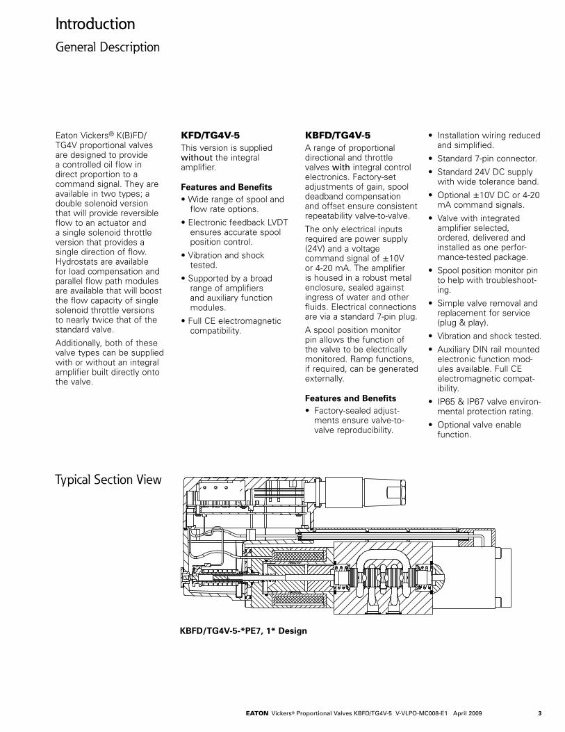
IntroductionGeneral Description
Eaton Vickers® K(B)FD/TG4V proportional valves are designed to provide a controlled oil flow in direct proportion to a command signal. They are available in two types; a double solenoid version that will provide reversible flow to an actuator and a single solenoid throttle version that provides a single direction of flow. Hydrostats are available for load compensation and parallel flow path modules are available that will boost the flow capacity of single solenoid throttle versions to nearly twice that of the standard valve.
Additionally, both of these valve types can be supplied with or without an integral amplifier built directly onto the valve.
KFD/TG4V-5This version is supplied without the integral amplifier.
Features and Benefits• Wide range of spool and
flow rate options.
• Electronic feedback LVDT ensures accurate spool position control.
• Vibration and shock tested.
• Supported by a broad range of amplifiers and auxiliary function modules.
• Full CE electromagnetic compatibility.
KBFD/TG4V-5A range of proportional directional and throttle valves with integral control electronics. Factory-set adjustments of gain, spool deadband compensation and offset ensure consistent repeatability valve-to-valve.
The only electrical inputs required are power supply (24V) and a voltage command signal of ±10V or 4-20 mA. The amplifier is housed in a robust metal enclosure, sealed against ingress of water and other fluids. Electrical connections are via a standard 7-pin plug.
A spool position monitor pin allows the function of the valve to be electrically monitored. Ramp functions, if required, can be generated externally.
Features and Benefits• Factory-sealed adjust-
ments ensure valve-to-valve reproducibility.
• Installation wiring reduced and simplified.
• Standard 7-pin connector.
• Standard 24V DC supply with wide tolerance band.
• Optional ±10V DC or 4-20 mA command signals.
• Valve with integrated amplifier selected, ordered, delivered and installed as one perfor-mance-tested package.
• Spool position monitor pin to help with troubleshoot-ing.
• Simple valve removal and replacement for service (plug & play).
• Vibration and shock tested.
• Auxiliary DIN rail mounted electronic function mod-ules available. Full CE electromagnetic compat-ibility.
• IP65 & IP67 valve environ-mental protection rating.
• Optional valve enable function.
Typical Section View
KBFD/TG4V-5-*PE7, 1* Design

4 EATON Vickers® Proportional Valves KBFD/TG4V-5 V-VLPO-MC008-E1 April 2009
Model Codes
321 764 985 17161110 1312 14 15 1918 2120
1 Valve Type K Proportional valve
2 Integral Amplifier B Integral amplifier “B” series. Omit for models without integral amplifier
3 Feedback Arrangement F Spool position
4 Control Type D Directional valve
T Throttle valve
5 MountingG Subplate mounted
6 Operation4 Solenoid operation
7 Pressure Rating V 315 bar (4500 psi) on ports P, A & B
8 Interface 5 ISO 4401, size 05-04-0-05 ANSI/B93.7M-D05. ISO 4401, size 05-06-0-05 (with L ports)
9 Spool Type (center condition)
(see spool data) 2 All ports closed9 All ports closed
(zero lap, 50N only)33 P port closed, bleed A &
B to T
10 Spool/Spring Arrangement
B Spring centered single solenoid valve (solenoid “B” only) Solenoid “A” for “V” version, throttle valveC Spring centered, dual solenoid, directional valve
11 Spool Flow Rating∆ p = 5 bar (75 psi) per metering flow path, e.g. B to T. (For actual maximum flow refer to power capacity envelope curves.)30 30 L/min
(7.9 USgpm) 50 50 L/min
(13.2 USgpm) 65 65 L/min
(17.2 USgpm) 70 70 L/min
(18.5 USgpm)
Meter-in/meter-out Meter-out only Type 2 spool only
12 Spool Metering Type N Meter-in and meter-outS Meter-out only
13 Flow Rating (“B” port flow for asymmetric spools) K(B)FDG Valves Only
25 25 L/min (6.6 USgpm) (50N25 only)
Omit for symmetrical spools
14 Manual Overrides Z No manual overrides
15 Solenoids Energization Identity
(non-integral amplifier types KF only, omit for valves with integral amplifier)V Solenoid “A” is at port
“A” end and Solenoid “B” is at port “B” end independent of spool type
Blank US ANSI B93.9 standard (energize solenoid “A”, flow symbol is (P→A)
16 Command Input (omit for valves with integral amplifier)M Electrical feature flag
(KF only)
M1 ±10VDC (KBF only)
M2 4-20 mA (KBF only)
17 Solenoid Connector (omit for valves with integral amplifier KBF)U1 ISO 4400/DIN 43650,
non-integral amplifier type KF only (mating plug supplied)
18 Electrical Connection (KBF valves only)
PC7 7-pin connector without plug
PE7 7-pin electrical plug with mating half
PH7 As PE7 but with pin “C” used for enable signal
PR7 As PC7 but with pin “C” used for enable signal
19 Coil Rating H 24 VDC amplifier
supply
20 Port T Pressure Limit Code
6 For 2C**S spools7 For all other spools
21 Design Number 1* & 2* Series
Subject to change
K (B) F * G 4 V - 5 - * * * * * * * * - Z - (V) - (M) - (U1)- (* * *) - H - * - *
WARNINGValves with integral amplifier
are supplied with or without the metal 7-pin plug. The Vickers plug, part no. 934939, must be correctly fitted to ensure that the EMC rating and IP67 rating are archieved. The plug retaining nut must be tightened with a torque of 2-2,5 Nm (1.5-2.0 lbf ft) to effect a proper a proper seal.
5EATON Vickers® Proportional Valves KBFD/TG4V-5 V-VLPO-MC008-E1 April 2009
P T B L P T B A L
P T B A LP T B A L
7-pinplug
A
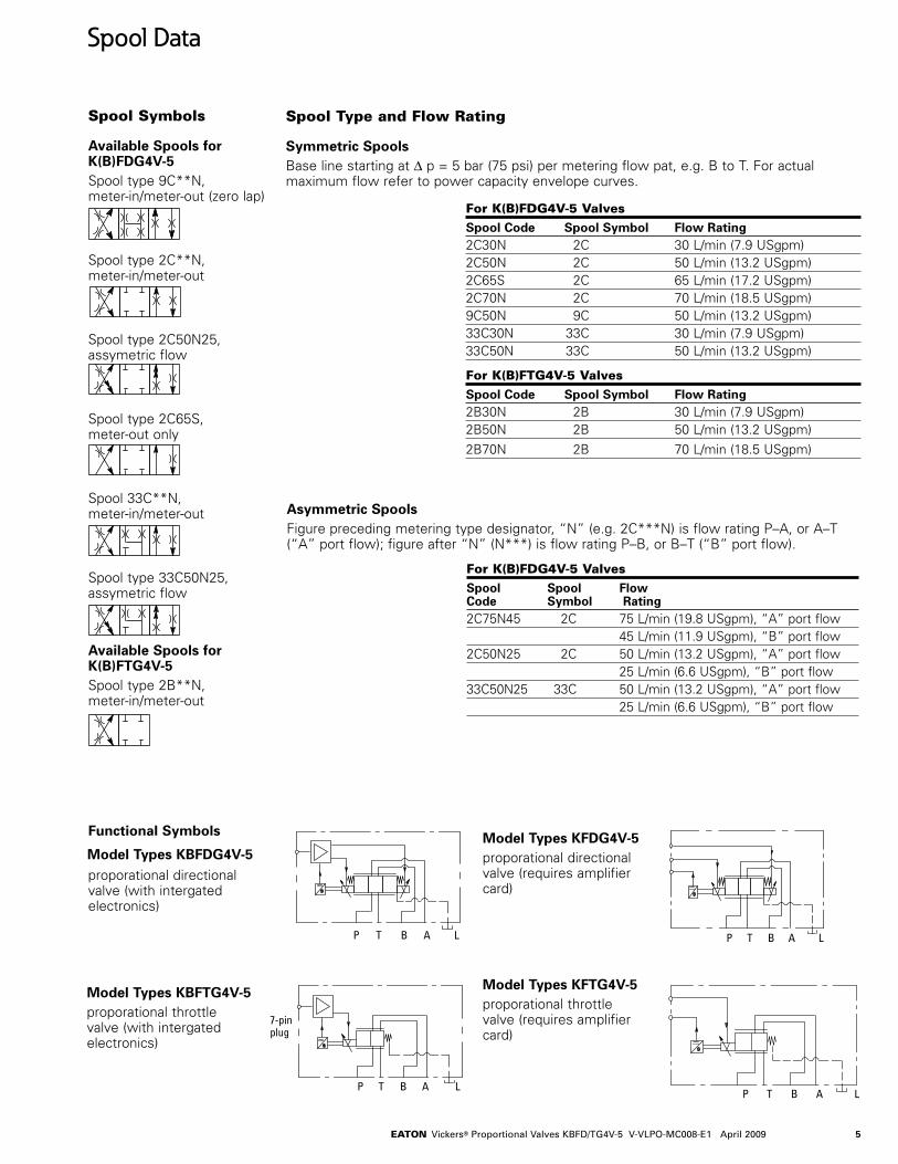
Spool Data
Spool Symbols
Available Spools for K(B)FDG4V-5Spool type 9C**N, meter-in/meter-out (zero lap)
Spool type 2C**N, meter-in/meter-out
Spool type 2C50N25, assymetric flow
Spool type 2C65S, meter-out only
Spool 33C**N, meter-in/meter-out
Spool type 33C50N25, assymetric flow
Available Spools for K(B)FTG4V-5Spool type 2B**N, meter-in/meter-out
Spool Type and Flow Rating
Symmetric SpoolsBase line starting at ∆ p = 5 bar (75 psi) per metering flow pat, e.g. B to T. For actual maximum flow refer to power capacity envelope curves.
Functional Symbols
Model Types KBFDG4V-5Model Types KFDG4V-5proporational directional valve (requires amplifier card)
Model Types KBFTG4V-5proporational throttle valve (with intergated electronics)
Model Types KFTG4V-5proporational throttle valve (requires amplifier card)
For K(B)FDG4V-5 Valves
Spool Spool Flow Code Symbol Rating2C75N45 2C 75 L/min (19.8 USgpm), “A” port flow 45 L/min (11.9 USgpm), “B” port flow2C50N25 2C 50 L/min (13.2 USgpm), “A” port flow 25 L/min (6.6 USgpm), “B” port flow33C50N25 33C 50 L/min (13.2 USgpm), “A” port flow 25 L/min (6.6 USgpm), “B” port flow
Asymmetric SpoolsFigure preceding metering type designator, “N” (e.g. 2C***N) is flow rating P–A, or A–T (“A” port flow); figure after “N” (N***) is flow rating P–B, or B–T (“B” port flow).
For K(B)FDG4V-5 Valves
Spool Code Spool Symbol Flow Rating2C30N 2C 30 L/min (7.9 USgpm)2C50N 2C 50 L/min (13.2 USgpm)2C65S 2C 65 L/min (17.2 USgpm)2C70N 2C 70 L/min (18.5 USgpm)9C50N 9C 50 L/min (13.2 USgpm)33C30N 33C 30 L/min (7.9 USgpm)33C50N 33C 50 L/min (13.2 USgpm)
For K(B)FTG4V-5 Valves
Spool Code Spool Symbol Flow Rating2B30N 2B 30 L/min (7.9 USgpm)2B50N 2B 50 L/min (13.2 USgpm)
2B70N 2B 70 L/min (18.5 USgpm)
proporational directional valve (with intergated electronics)

6 EATON Vickers® Proportional Valves KBFD/TG4V-5 V-VLPO-MC008-E1 April 2009
Operating DataK(B)FD/TG4V-5Valves with Amplifier
KBFD/TG4V-5 Valves with Integral Amplifier
Data is typical with fluid at 36 cSt (168 SUS) and 50° C (122° F).Power supply 24V DC (21 V to 36V including 10% peak-to-peak max. ripple)
max current 3ACommand signal Voltage mode M1 0 to +10V DC, or 0 to -10V DC, or -10V to +10V DC Input impedance 47 Ω Common mode voltage to pin D 18V (max) Current mode M2 4-20 mA Input impedance 100 Ω Max differential voltage to Pin E to Pin B 100mV Valve enable signal for model codes PH7 & PR7 Enable >8.5V (36V max) Disable <6.5 V Input impedance 10 Ω7-pin plug connector Pin Description A Power supply positive (+) B Power supply 0V and current command return C Not connected (PE7 & PC7) C Valve enable (PH7 & PR7) D Command signal (+V or current IN) E Command signal (–V or current GND) F Mounting input G Protective groundElectromagnetic compatibility (EMC) Emmision (10V/m) EN 61326-2 Immunity (10V/m) EN 61326-2Threshold command voltage (minimum voltage for minimum flow) 0.25VMonitor signal (pin F) KBFD valves ± 10V DC for full spool stroke KBFT valves 0 to –10 V DC for full spool stroke Output impedance 10 ΩPower stage PWM frequency 10 kHz nominalStep input response with flow through P–A–B–T ∆ p = 5 bar (75 psi) per metering path, e.g. P–A Required flow step: Time to reach 90% of required step: 0 – 100% 30 ms 100% – 0 40 ms +90 – -90% (KBFDG4V3-3 only) 32 msReproducibility, valve-to-valve (at factory settings): Flow at 100% command signal ≤ 5%Protection Electrical Reverse polarity protected Environmental IEC 60529, Class IP65 & IP67Ambient air temperature range for full performance 0° C to 70° C (32° F to 158° F) Oil temperature range for full performance 0° C to 70° C (32° F to 158° F)Mimimum temperature at which -20° C (-4° F) valves will work at reduced performanceStorage temperature range -25° C to +85° C (-13° F to +185° F)
Supporting products Auxiliary electronic modules (DIN -rail mounting): EHD-DSG-201-A-1* command signal generator See catalog GB 2470 EHA-RMP-201-A-2* Ramp generator See catalog GB 2410A EHA-PSU-201-A-10 Power supply See catalog GB 2410A EHA-PID-201-A-20 PID controller See catalog GB 2427
Operating Data
F
A G
B
C
D
E
7EATON Vickers® Proportional Valves KBFD/TG4V-5 V-VLPO-MC008-E1 April 2009
Operating DataKFD/TG4V-5Valves without Amplifier
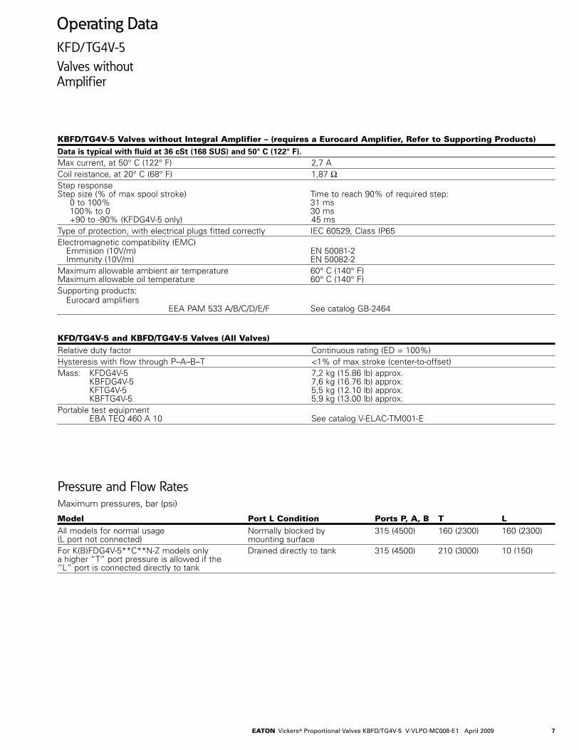
KBFD/TG4V-5 Valves without Integral Amplifier – (requires a Eurocard Amplifier, Refer to Supporting Products)
Data is typical with fluid at 36 cSt (168 SUS) and 50° C (122° F).Max current, at 50° C (122° F) 2,7 ACoil reistance, at 20° C (68° F) 1,87 ΩStep response Step size (% of max spool stroke) Time to reach 90% of required step: 0 to 100% 31 ms 100% to 0 30 ms +90 to -90% (KFDG4V-5 only) 45 msType of protection, with electrical plugs fitted correctly IEC 60529, Class IP65 Electromagnetic compatibility (EMC) Emmision (10V/m) EN 50081-2 Immunity (10V/m) EN 50082-2Maximum allowable ambient air temperature 60° C (140° F) Maximum allowable oil temperature 60° C (140° F)Supporting products: Eurocard amplifiers EEA PAM 533 A/B/C/D/E/F See catalog GB-2464
KFD/TG4V-5 and KBFD/TG4V-5 Valves (All Valves)
Relative duty factor Continuous rating (ED = 100%)Hysteresis with flow through P–A–B–T <1% of max stroke (center-to-offset)Mass: KFDG4V-5 7,2 kg (15.86 lb) approx. KBFDG4V-5 7,6 kg (16.76 lb) approx. KFTG4V-5 5,5 kg (12.10 lb) approx. KBFTG4V-5 5,9 kg (13.00 lb) approx.Portable test equipment EBA TEQ 460 A 10 See catalog V-ELAC-TM001-E
Pressure and Flow RatesMaximum pressures, bar (psi)
Model Port L Condition Ports P, A, B T L
All models for normal usage Normally blocked by 315 (4500) 160 (2300) 160 (2300) (L port not connected) mounting surface For K(B)FDG4V-5**C**N-Z models only Drained directly to tank 315 (4500) 210 (3000) 10 (150) a higher “T” port pressure is allowed if the “L” port is connected directly to tank
8 EATON Vickers® Proportional Valves KBFD/TG4V-5 V-VLPO-MC008-E1 April 2009
(A)
P
B
(T)
0 40 80 120 160
0 10 20 30 40 50 USgpm 0 10 20 30 40 50 USgpmFlow rate
100
200
300315
0
1000
2000
3000
40004500psi bar
A
P
(B)
(T)
(A)
P
B
(T)
or
0 40 80 120 160
Flow rate
100
200
300315
0
1000
2000
3000
40004500psi bar
A
P
B
Tor
A
P
B
T
081
0 40 80 120 160
040 10 20 30 50 USgpmFlow rate
100
200
300315
0
1000
2000
3000
40004500
psi bar
180
0 40 80 120 160
040 10 20 30 50 USgpmFlow rate
100
200
300315
0
1000
2000
3000
40004500psi bar
Valv
e pr
essu
re d
rop
Valv
e pr
essu
re d
rop
Valv
e pr
essu
re d
rop
Valv
e pr
essu
re d
rop
Valv
e pr
essu
re d
rop
Looped Flow Path
A
P
B
T
180 L/min
0 60 120 180 240
0 4010 20 30 50 USgpmFlow rate
100
200
300315
0
1000
2000
3000
40004500
psi bar
A
P
B
T
60
Max. system pressure = max. for port T: 210 bar (3000psi)
300
70 80
2 B30 N2B50N 2B70N
2B30N 2B50N
2B70N
2B70N
2B50N
**C30N
**C50N2C70N
2C6 5 S
2C 7 0 N
**C 5 0 N* * C 3 0 N
L/min
180 L/minL/min
L/min
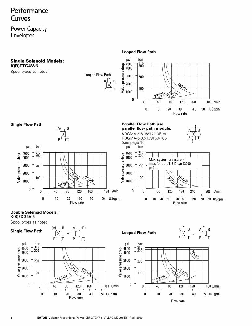
Performance CurvesPower Capacity Envelopes
Single Solenoid Models: K(B)FTG4V-5Spool types as noted
Parallel Flow Path use parallel flow path module:KDGMA-5-616877-10R or KDGMA-5-02-139150-10S (see page 16)
Single Flow Path
Double Solenoid Models: K(B)FDG4V-5 Spool types as noted
Single Flow Path Looped Flow Path
Looped Flow Path
9EATON Vickers® Proportional Valves KBFD/TG4V-5 V-VLPO-MC008-E1 April 2009
KFD/TG4V-5
1 2 3 4 5 10
0
+3
–3
–6
20 30 40 60 80
135
90
450
Frequency (Hz)
)seerge
d( gal esa
hP
)B
d( oitar e
dutil
pm
A
1 2 3 4 5 10
0
+3
–3
–6
20 30 40 60 80
135
90
45
0
Frequency (Hz)
)seerge
d( gal esa
hP
)B
d( oitar e
dutil
pm
A
KBFD/TG4V-5
L/min70
40
20
0 20 40 60 80 100
Command signal (% of max.)
USgpm
0
5
10
15
20
60
N07C2 ,N07B2
S56C2
N05C** ,N05B2
2B30N, **C30N
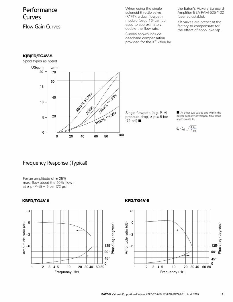
Performance CurvesFlow Gain Curves
K(B)FD/TG4V-5Spool types as noted
When using the single solenoid throttle valve (K*FT), a dual flowpath module (page 16) can be used to approximately double the flow rate.
Curves shown include deadband compensation provided for the KF valve by
the Eaton’s Vickers Eurocard Amplifier EEA-PAM-535-*-32 (user adjustable).
KB valves are preset at the factory to compensate for the effect of spool overlap.
Frequency Response (Typical)
Qx = Qd∆ px∆ pd
For an amplitude of ± 25% max. flow about the 50% flow , at ∆ p (P–B) = 5 bar (72 psi)
At other ∆ p values and within the power capacity envelopes, flow rates approximate to:
Single flowpath (e.g. P–A) pressure drop, ∆ p = 5 bar (72 psi) .
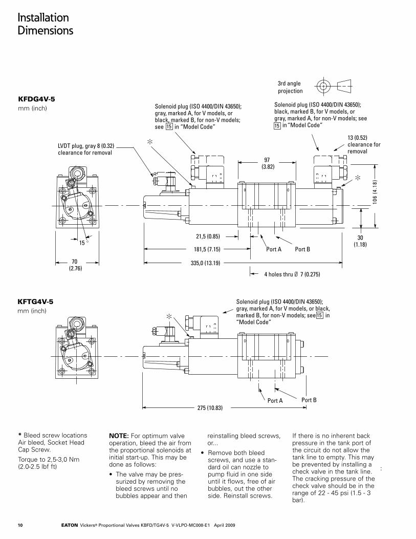
10 EATON Vickers® Proportional Valves KBFD/TG4V-5 V-VLPO-MC008-E1 April 2009
3rd angleprojection
70 (2.76)
97(3.82)
13 (0.52)clearance forremoval
335,0 (13.19)
181,5 (7.15)
Solenoid plug (ISO 4400/DIN 43650);black, marked B, for V models, orgray, marked A, for non-V models; see in “Model Code”15
Solenoid plug (ISO 4400/DIN 43650);gray, marked A, for V models, orblack, marked B, for non-V models;see in “Model Code”
Port A Port B
21,5 (0.85) 30(1.18)
LVDT plug, gray 8 (0.32) clearance for removal
Solenoid plug (ISO 4400/DIN 43650);gray, marked A, for V models, or black,marked B, for non-V models; see in“Model Code”
)81.4( 601
15
4 holes thru Ø 7 (0.275)
275 (10.83)Port A Port B
15
:
15
Installation Dimensions
NOTE: For optimum valve operation, bleed the air from the proportional solenoids at initial start-up. This may be done as follows:
• The valve may be pres-surized by removing the bleed screws until no bubbles appear and then
reinstalling bleed screws, or...
• Remove both bleed screws, and use a stan-dard oil can nozzle to pump fluid in one side until it flows, free of air bubbles, out the other side. Reinstall screws.
If there is no inherent back pressure in the tank port of the circuit do not allow the tank line to empty. This may be prevented by installing a check valve in the tank line. The cracking pressure of the check valve should be in the range of 22 - 45 psi (1.5 - 3 bar).
* Bleed screw locations Air bleed, Socket Head Cap Screw.
Torque to 2,5-3,0 Nm (2.0-2.5 lbf ft)
KFDG4V-5mm (inch)
KFTG4V-5mm (inch)

11EATON Vickers® Proportional Valves KBFD/TG4V-5 V-VLPO-MC008-E1 April 2009
7 pin connector plug
Fixing bolt
174(6.85)
328(12.91)
85(3.34)
135(5.31)
70 (2.76)
174(6.85)
268(10.55)
X X
XX30 (1.18)
Port APort B
Port A Port B
21,5 (0.85)
Installation Dimensions
NOTE: For optimum valve operation, bleed the air from the proportional solenoids at initial start-up. This may be done as follows:
• The valve may be pres-surized by removing the bleed screws until no bubbles appear and then
reinstalling bleed screws, or...
• Remove both bleed screws, and use a stan-dard oil can nozzle to pump fluid in one side until it flows, free of air bubbles, out the other side. Reinstall screws.
If there is no inherent back pressure in the tank port of the circuit do not allow the tank line to empty. This may be prevented by installing a check valve in the tank line. The cracking pressure of the check valve should be in the range of 22 - 45 psi (1.5 - 3 bar).
Warning
Valves with integral amplifiers are
supplied with or without the metal 7-pin plug. The Eaton plug, part no. 934939, must be correctly fitted to ensure that the EMC rating and IP67 rating are achieved. The plug retaining nut must be tightened with a torque of 2,0-2,5 Nm (1.5-2.0 lbf ft) to effect a proper seal.
* Bleed screw locations Air bleed, Socket Head Cap Screw.
Torque to 2,5-3,0 Nm (2.0-2.5 lbf ft)
KBFDG4V-5mm (inch)
KBFTG4V-5mm (inch)

12 EATON Vickers® Proportional Valves KBFD/TG4V-5 V-VLPO-MC008-E1 April 2009
Subplates and Mounting Surfaces
General DescriptionIf a subplate is not used, a machined pad must be provided for valve mounting. Pad must be flat within 0,0127 mm (.0005 inch) and smooth within 1,6 µm (63 microinch). Mounting bolts, when provided by customer, should be ISO 898 class 12.9 or better.
Dimensional TolerancesDimensional tolerance on interface drawings is ± 0,2 mm (±0.008”) except where otherwise stated. ISO 4401 specifies inch conversion to ± 0.01”.
Conversion for MetricISO 4401 gives dimensions in mm. Inch conversons are accurate to 0.01” unless othewise stated.
Mounting Bolt TappingISO 4401 gives metric thread tappings. Alternate UNC tapping are Eaton’s recommendations that allow these plates and associated valves to be used up to their maximum pressures, when using Eaton recommended bolt kits, or bolts of an equivalent strength. It is recommended that customer’s own manifold blocks for UNC bolts should be tapped to the minimum depths given in the footnotes.
Subplates
Description and Mass kg (lb) Fucntional Symbol Model Code Max. PressureSingle-station subplate; KDGSM-5-67805-20 210 bar (3000 psi) rear ports P, T, A, B; side port L (SAE/UNF ports) Cast iron 1,3 (2.9) KDGSM-5-615225-10 315 bar (4500 psi) 1/2” BSPF ports KDGSM-5-615226-10 3/4”BSPF ports EKDGSM-01Y-10-R 280 bar (4000 psi)
P T B A L
L
P T B A
13EATON Vickers® Proportional Valves KBFD/TG4V-5 V-VLPO-MC008-E1 April 2009
13
11,5(0.45)
P
A B
T
N
M
101,6 (4.0)
12,7 (0.5)
79,4 (3.12)
68,3(2.7)
23,1(0.9)
11,2 (0.44)
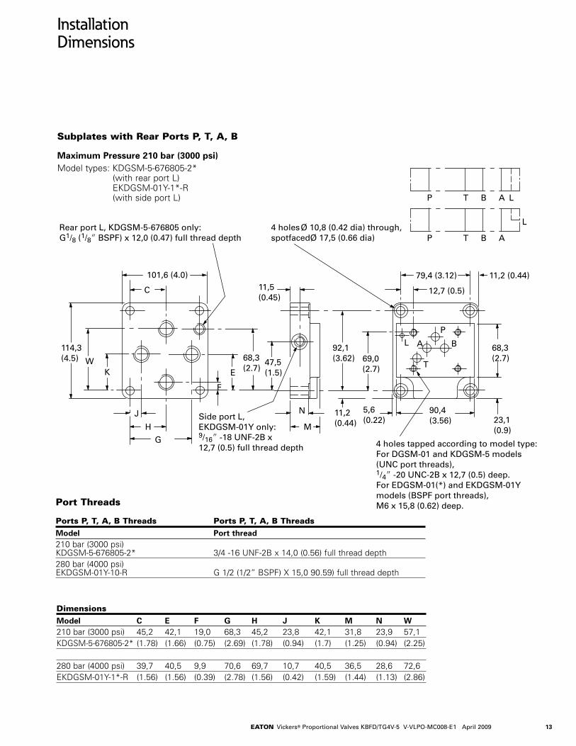
4 holes Ø 10,8 (0.42 dia) through,spotfacedØ 17,5 (0.66 dia)
4 holes tapped according to model type:For DGSM-01 and KDGSM-5 models(UNC port threads),1/4 -20 UNC-2B x 12,7 (0.5) deep.For EDGSM-01(*) and EKDGSM-01Ymodels (BSPF port threads), M6 x 15,8 (0.62) deep.
92,1(3.62)
114,3(4.5)
P T B A L
L
P T B A
L
WK E
69,0(2.7)
F
68,3(2.7)
47,5(1.5)
C
H
J
G
90,4(3.56)
5,6(0.22)Side port L,
EKDGSM-01Y only:9/16 -18 UNF-2B x 12,7 (0.5) full thread depth
Rear port L, KDGSM-5-676805 only:G1/8 (1/8 BSPF) x 12,0 (0.47) full thread depth
11,2(0.44)
Installation Dimensions
Subplates with Rear Ports P, T, A, B
Maximum Pressure 210 bar (3000 psi)Model types: KDGSM-5-676805-2*
(with rear port L) EKDGSM-01Y-1*-R (with side port L)
Port Threads
Ports P, T, A, B Threads Ports P, T, A, B Threads
Model Port thread210 bar (3000 psi) KDGSM-5-676805-2* 3/4 -16 UNF-2B x 14,0 (0.56) full thread depth280 bar (4000 psi) EKDGSM-01Y-10-R G 1/2 (1/2” BSPF) X 15,0 90.59) full thread depth
Dimensions
Model C E F G H J K M N W210 bar (3000 psi) 45,2 42,1 19,0 68,3 45,2 23,8 42,1 31,8 23,9 57,1KDGSM-5-676805-2* (1.78) (1.66) (0.75) (2.69) (1.78) (0.94) (1.7) (1.25) (0.94) (2.25)
280 bar (4000 psi) 39,7 40,5 9,9 70,6 69,7 10,7 40,5 36,5 28,6 72,6EKDGSM-01Y-1*-R (1.56) (1.56) (0.39) (2.78) (1.56) (0.42) (1.59) (1.44) (1.13) (2.86)

14 EATON Vickers® Proportional Valves KBFD/TG4V-5 V-VLPO-MC008-E1 April 2009
14
LP T B A
P
A B
T
89,0 (3.5)
80,0 (3.15)
67,0(2.6)
4 holes M6 x14,0 (0.55) fullthread depth
115,0(4.6)L
46,0(1.81)
77,5(3.1)
88,0 (3.5)
Port L, G1/4 (1/4 BSPF) x 12,0 (0.47),spotfaced to Ø 24,0 (0.94 dia)
120,0 (4.8)
23,0(0.9)
92,0(3.62)
17,0(0.7)
47,5(1.9)
12,5 (0.5)
Z Y
42,0(1.7)
Port L, Ø 4,0 (0.16 dia)
Ports P, T, A, B,Ø 10,5 (0.41 dia)
Part Section A-A
40,0(1.6)
5,0(0.2) A
A
Recommended panel cut-out toclear fittings,Ø 108,0 (4.25 dia)
75,0(3.0)
4 holes Ø 10,5 (0.41 dia)
13,0 (0.51)
1,0(0.04)
Installation Dimensions
Subplates with Rear Ports P, T, A, B, L
Maximum Pressure 315 bar (4500 psi)Model types: KDGSM-5-615225-1*
KDGSM-5-615226-1*
All dimensions in mm (inches)
Ports P, T, A, B
Model Y Thread Z DiameterKDGSM-5-615225-10 G1/2 (1/2” BSPF) x 14,0 (0.55) full thread depth 30,0 (1.18)KDGSM-5-615226-10 G3/4 (3/4” BSPF) X 16,0 (0.63) full thread depth 33,0 (1.30)
15EATON Vickers® Proportional Valves KBFD/TG4V-5 V-VLPO-MC008-E1 April 2009
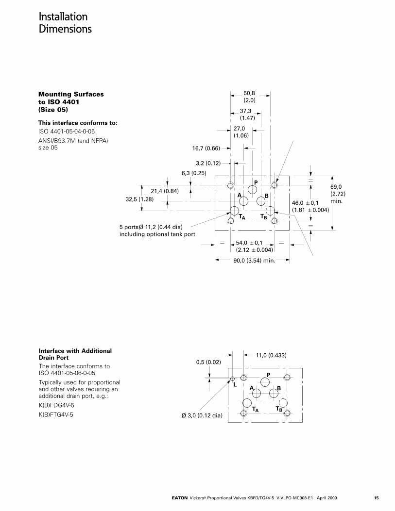
Installation Dimensions
Mounting Surfaces to ISO 4401 (Size 05)
This interface conforms to:ISO 4401-05-04-0-05
ANSI/B93.7M (and NFPA) size 05
Interface with Additional Drain PortThe interface conforms to ISO 4401-05-06-0-05
Typically used for proportional and other valves requiring an additional drain port, e.g.:
K(B)FDG4V-5
K(B)FTG4V-5
15
37,3(1.47)
5 ports Ø 11,2 (0.44 dia)including optional tank port
27,0(1.06)
16,7 (0.66)
6,3 (0.25)
3,2 (0.12)
50,8(2.0)
46,0 0,1(1.81 0.004)
32,5 (1.28)
90,0 (3.54) min.
P
A B
TA TB
54,0 0,1(2.12 0.004)
69,0(2.72)min.
21,4 (0.84)
P
A B
TA TB
0,5 (0.02)11,0 (0.433)
L
Ø 3,0 (0.12 dia)
16 EATON Vickers® Proportional Valves KBFD/TG4V-5 V-VLPO-MC008-E1 April 2009
16
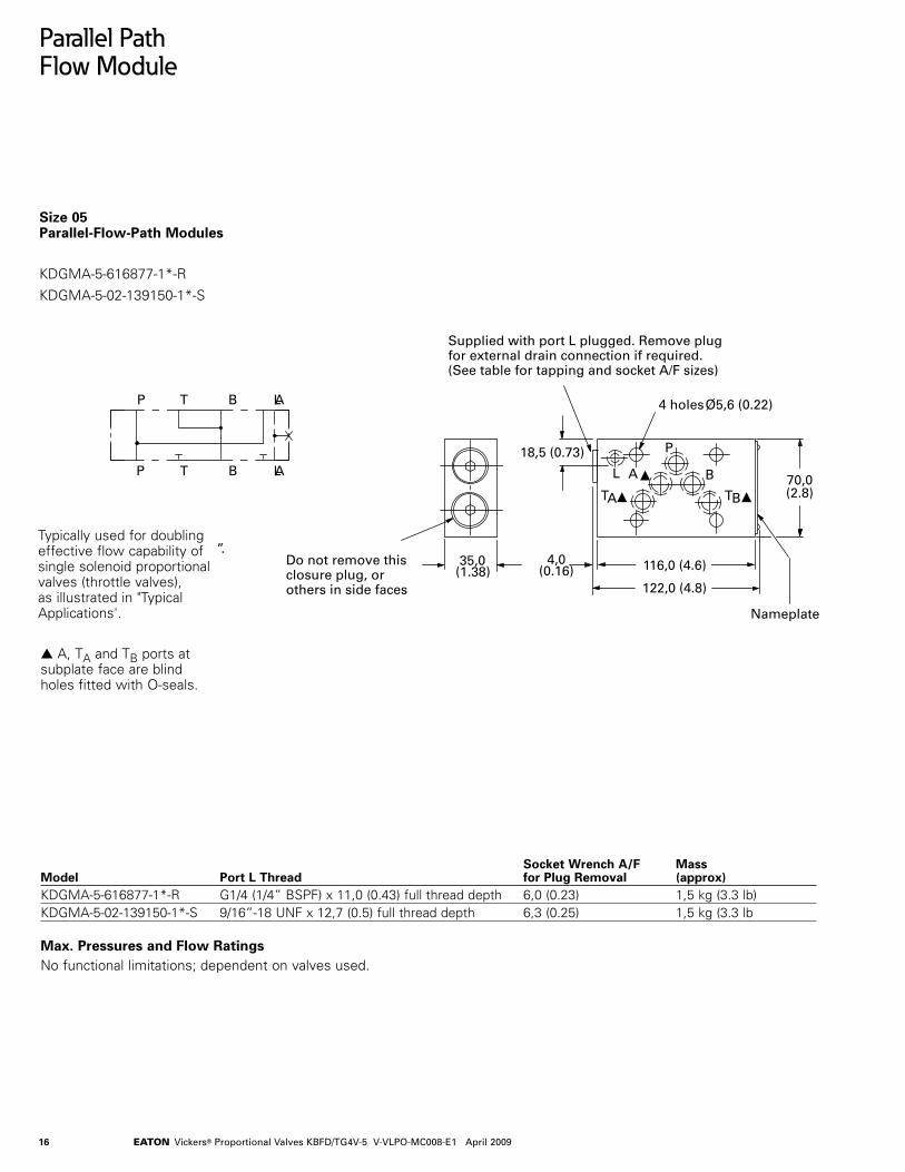
Parallel Path Flow Module
”.
P T B A
P T B A
L
L
35,0(1.38)
4,0(0.16)
4 holes Ø5,6 (0.22)
A
TA
L
P
Do not remove thisclosure plug, orothers in side faces
Supplied with port L plugged. Remove plugfor external drain connection if required.(See table for tapping and socket A/F sizes)
TB
B
122,0 (4.8)
116,0 (4.6)
70,0(2.8)
18,5 (0.73)
Nameplate
Parallel Path Flow Module
Size 05 Parallel-Flow-Path Modules
KDGMA-5-616877-1*-R
KDGMA-5-02-139150-1*-S
A, TA and TB ports at subplate face are blind holes fitted with O-seals.
Socket Wrench A/F Mass Model Port L Thread for Plug Removal (approx)KDGMA-5-616877-1*-R G1/4 (1/4” BSPF) x 11,0 (0.43) full thread depth 6,0 (0.23) 1,5 kg (3.3 lb)KDGMA-5-02-139150-1*-S 9/16”-18 UNF x 12,7 (0.5) full thread depth 6,3 (0.25) 1,5 kg (3.3 lb
Max. Pressures and Flow RatingsNo functional limitations; dependent on valves used.
Typically used for doubling effective flow capability of single solenoid proportional valves (throttle valves), as illustrated in "Typical Applications'.
17EATON Vickers® Proportional Valves KBFD/TG4V-5 V-VLPO-MC008-E1 April 2009
Electrical Information
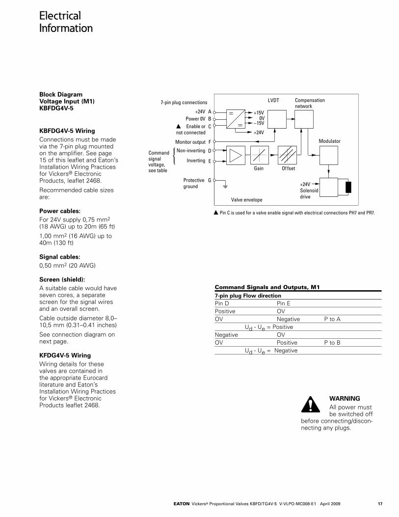
Block Diagram Voltage Input (M1) KBFDG4V-5
KBFDG4V-5 WiringConnections must be made via the 7-pin plug mounted on the amplifier. See page 15 of this leaflet and Eaton’s Installation Wiring Practices for Vickers® Electronic Products, leaflet 2468.
Recommended cable sizes are:
Power cables:For 24V supply 0,75 mm2 (18 AWG) up to 20m (65 ft)
1,00 mm2 (16 AWG) up to 40m (130 ft)
Signal cables:0,50 mm2 (20 AWG)
Screen (shield):A suitable cable would have seven cores, a separate screen for the signal wires and an overall screen.
Cable outside diameter 8,0–10,5 mm (0.31–0.41 inches)
See connection diagram on next page.
KFDG4V-5 WiringWiring details for these valves are contained in the appropriate Eurocard literature and Eaton’s Installation Wiring Practices for Vickers® Electronic Products leaflet 2468.
Command Signals and Outputs, M1
7-pin plug Flow directionPin D Pin EPositive OVOV Negative P to A Ud - Ue = PositiveNegative OVOV Positive P to B Ud - Ue = Negative
Of fset
Modulator
Valve envelope
7-pin plug connections
+24V AB
D
E
F
G
Power 0V Enable or
not connected
Protective ground
Non-inverting
InvertingCommandsignalvoltage,see table
Compensationnetwork
+15V0V
–15V
+24V
LVDT
C
Monitor output
Gain
+24V Solenoid drive
Pin C is used for a valve enable signal with electrical connections PH7 and PR7.
WARNINGAll power must be switched off
before connecting/discon-necting any plugs.

18 EATON Vickers® Proportional Valves KBFD/TG4V-5 V-VLPO-MC008-E1 April 2009
Electrical Information
Block Diagram Current Input (M2) KBFDG4V-5
KBFDG4V-5 WiringConnections must be made via the 7-pin plug mounted on the amplifier. See page 15 of this leaflet and Eaton’s Installation Wiring Practices for Vickers® Electronic Products, leaflet 2468.
Recommended cable sizes are:
Power cables:For 24V supply
0,75 mm2 (18 AWG) up to 20m (65 ft) 1,00 mm2 (16 AWG) up to 40m (130 ft)
Signal cables: 0,50 mm2 (20 AWG)
Screen (shield):A suitable cable would have seven cores, a separate screen for the signal wires and an overall screen.
Cable outside diameter 8,0–10,5 mm (0.31–0.41 inches)
See connection diagram on next page.
KFDG4V-5 WiringWiring details for these valves are contained in the appropriate Eurocard literature and Eaton’s Installation Wiring Practices for Vickers® Electronic Products leaflet 2468.
Command Signals and Outputs, M2
7-pin plugPin D Pin E Pin B Flow directionMore than Current Power 12 mA return ground P to ALess than Current Power 12 mA return ground P to B
WARNINGAll power must be switched off
before connecting/discon-necting any plugs.
Offset
Modulator
Valve envelope
7-pin plug connections
+24V AB
D
E
F
G
Power 0V Enable or
not connected
Protective ground
Command +4 to 20 mA
Compensation network
+15V0V
-15V
+24V
LVDT
C
Monitor output
+24V Solenoid drive
Gain
F1
R1
F2
Return
Pin C is used for a valve enable signal with electrical connections PH7 and PR7.
R1 shunt resistor 100R
F1, F2 resettable fuse
19EATON Vickers® Proportional Valves KBFD/TG4V-5 V-VLPO-MC008-E1 April 2009
Electrical Information
Wiring Connections Voltage Input (M1) Spool position monitor voltage (pin F) will be referenced to the KB valve local ground.
WARNINGDo not ground pin C.
Wiring Connections for M1 Valves with Enable Feature Note: In applications where the valve must conform to European RFI/EMC regulations, the outer screen (shield) must be connected to the outer shell of the 7-pin connector, and the valve body must be fastened to the earth ground. Proper earth grounding practices must be observed in this case, as any differences in command source and valve ground potentials will result in a screen (shield) ground loop.
Input
User Panel
Power Supply
Demand Signal
SpoolPosition Monitor
0V must be connected to ground
Enclosure
+24V0V
±10V
Connector shell
Outer Screen KB..PC7/PE7 valve
A
B
D or E0V
0V
C
Drain Wire
Inner Screen
G
F
Valve must be connected to ground via subplate
0V
Input
User Panel
Power Supply
Demand Signal
SpoolPosition Monitor
+24V
±10V
Connector shell
Outer Screen
AB
D or E
0V
0V
C
Drain Wire
Inner Screen
E or D
G
F
KB..PR7/PH7 valve
Enable Signal
+8.5Vto 36V
0V
Enclosure
Valve must be connected to ground via subplate
0V must be connected to ground
20 EATON Vickers® Proportional Valves KBFD/TG4V-5 V-VLPO-MC008-E1 April 2009
Electrical Information
Wiring Connections Current Input (M2) Spool position monitor voltage (pin F) will be referenced to the KB valve local ground.
WARNINGDo not ground pin C.
Wiring Connections for M2 Valves with Enable Feature Note: In applications where the valve must conform to European RFI/EMC regulations, the outer screen (shield) must be connected to the outer shell of the 7-pin connector, and the valve body must be fastened to the earth ground. Proper earth grounding practices must be observed in this case, as any differences in command source and valve ground potentials will result in a screen (shield) ground loop.
WARNINGElectromagnetic
Compatibility (EMC)
It is necessary to ensure that the valve is wired up as above. For effective protection the user electrical cabinet, the valve subplate or manifold and the cable screens should be connected to efficient ground points.
The metal 7-pin connector part no. 934939 should be used for the integral amplifier. In all cases both valve and cable should be kept as far away as possible from any sources of elec-tromagnetic radiation such as cables carrying heavy current, relays and certain kinds of portable radio
transmitters, etc. Difficult environments could mean that extra screening may be necessary to avoid the interference.
It is important to connect the 0V lines as shown above. The multi-core cable should have at least two screens to separate the
Input
User Panel
Power Supply
Demand Signal
SpoolPosition Monitor
0V must be connected to ground
Enclosure
+24V
4 - 20 mA
0V
Valve must be connected to ground via subplate
Connector shell
Outer Screen KB..PC7/PE7 valve
A
B
E0V
0V
C
Drain Wire
Inner Screen
G
F
D
0V
Input
User Panel
Power Supply
Demand Signal
SpoolPosition Monitor
+24V
Connector shell
4 - 20 mA
Outer Screen
AB
E
0V
0V
C
Drain Wire
Inner Screen
D
G
F
KB..PR7/PH7 valve
0V must be connected to ground
Enable Signal
+8.5Vto 36V
0V
Enclosure
Valve must be connected to ground via subplate
demand signal and monitor output from the power lines.
The enable line to pin C should be outside the screen which contains the demand signal cables.
21EATON Vickers® Proportional Valves KBFD/TG4V-5 V-VLPO-MC008-E1 April 2009
Application Data
Fluid CleanlinessProper fluid condition is essential for long and satisfactory life of hydraulic components and systems. Hydraulic fluid must have the correct balance of cleanliness, materials and additives for protection against wear of components, elevated viscosity and inclusion of air.
Recommendations on contamination control methods and the selection of products to control fluid condition are included in Eaton’s publication 9132 or 561, “Vickers Guide to Systemic Contamination Control”. The book also includes information on the Eaton’s concept of “ProActive Maintenance”.
The following recommendations are based on ISO cleanliness levels at 2 µm, 5 µm and 15 µm:
For products in this catalog the recommended levels are:
0 to 70 bar (1000 psi) . . . . . . . . . . . . . . 18/16/13
70 + bar (1000 + psi) . . . . . . . . . . . . . . . 17/15/12
Eaton products, as any components, will operate with apparent satisfaction in fluids with higher cleanliness codes than those described. Other manufacturers will often recommend levels above those specified.
Experience has shown, however, that life of any hydraulic components is shortened in fluids with higher cleanliness codes than those listed above. These codes have been proven to provide a long trouble-free service life for the products shown, regardless of the manufacturer.
Hydraulic FluidsMaterials and seals used in these valves are compatible with antiwear hydraulic oils, and non-alkyl-based phosphate esters. The extreme operating viscosity range is 500 to 13 cSt (2270 to 70 SUS) but the recommended running range is 54 to 13 cSt (245 to 70 SUS). For further technical information about fluids see “Technical Information” leaflet B-920 or I-286S.
InstallationThe proportional valves in this catalog can be mounted in any attitude, but it may be necessary in certain demanding applications, to ensure that the solenoids are kept full of hydraulic fluid. Good installation practice dictates that the tank port and any drain port are piped so as to keep the valves full of fluid once the system start-up has been completed.
Mounting Bolt Kits
For K(B)FD/TG4V-5BK534569M (metric),534569; M6x45 mmBK590737 (inch), 590737; 1/4”-20x1.75”If not using Eaton recommended bolt kits, bolts used should be to ISO 898, 12.9 or better.
Seal KitsKFD/TG4V-5 . . . . . . . . . . . . . . . . . . . . . . . . 565110
KBFD/TG4V-5-1* . . . . . . . . . . . . . . . . . .02-332751
Plugs
KBFDG4V7-pin plug (metal) . . . . . . . . . . . . . . . . . . . . 934939
7-pin plug (plastic). . . . . . . . . . . . . . . . . . . . 694534
(metal plug must be used for full EMC protection)
NOTE: An alternative metal connector which gives EMC protection but not IP67 rating is available from ITT-Cannon, part number CA06-COM-E-14S-A7-S.
KFDG4VSolenoid (black) . . . . . . . . . . . . . . . . . . . . . 710775
Solenoid (gray) . . . . . . . . . . . . . . . . . . . . . . 710776
LVDT (gray) . . . . . . . . . . . . . . . . . . . . . . . . . 458939
Extension CableExtension Cable: Adapter for extending seven core cable when changing from KA to KB valve and existing wiring is not long enough. Consists of a 7-pin plug, a 7-pin socket and a length of cable, fully assembled for ease of use.
Extension Cable . . . . . . . . . . . . . . . . . . . . . 944450
Service InformationThe products from this range are preset at the factory for optimum performance; disassembling critical items would destroy these settings. It is therefore recommended that should any mechanical or electronic repair be necessary they should be returned to the nearest Eaton repair center. The products will be refurbished as necessary and retested to specification before return.
Field repair is restricted to the replacement of the seals.
NOTE: The feedback/solenoid assembly installed in this valve should not be disassembled.

Eaton Hydraulics Group USA14615 Lone Oak RoadEden Prairie, MN 55344USATel: 952-937-9800Fax: 952-294-7722www.eaton.com/hydraulics
Eaton Hydraulics Group EuropeRoute de la Longeraie 71110 MorgesSwitzerlandTel: +41 (0) 21 811 4600Fax: +41 (0) 21 811 4601
Eaton Hydraulics Group Asia Pacific 11th Floor Hong Kong New World Tower 300 Huaihai Zhong Road Shanghai 200021 China Tel: 86-21-6387-9988 Fax: 86-21-6335-3912
© 2009 Eaton CorporationAll Rights ReservedPrinted in USADocument No. V-VLPO-MC008-E1April 2009