
VESSEL IG Pendant Rev Amultimedia.3m.com/mws/media/979090O/vessel-by-3mtm... · Remove the...
12
VESSEL Installation Guide Pendant by 3M + Todd Bracher ™
Transcript of VESSEL IG Pendant Rev Amultimedia.3m.com/mws/media/979090O/vessel-by-3mtm... · Remove the...

VESSEL Installation GuidePendantby 3M + Todd Bracher™

2
VESSEL Installation GuidePendantby 3M + Todd Bracher™
Application
Model Number: (VSL-PD-XX-XX-XXX; All Finishes)
VESSEL by 3M + Todd Bracher (the “Product”) is a decorative LED luminaire for dry, interior use. The Product is intended for ceiling-mounted LED lighting for commercial and residential use. Use in any other application has not been evaluated by 3M and may lead to an unsafe condition.
Safety Information
Please read, understand and follow all safety information contained in this Installation Guide prior to the installation of the Product. Retain these instructions at the installation site for future reference.
WARNING: Indicates a potentially hazardous situation, which, if not avoided, could result in death
or serious injury and/or property damage.
CAUTION: Indicates a potentially hazardous situation, which, if not avoided, could result in minor
or moderate injury and/or property damage.
To reduce risk associated with environmental contamination:
• At the end of product life, dispose of electronic waste in accordance with applicable local and
government regulations.
To reduce risk associated with hazardous voltage and fire:
• Disconnect the power source before any installation, maintenance or servicing.
• Only use power supplies provided by 3M.
• Always install the Product in accordance with the enclosed Installation Instructions.
• Do not use this Product if damaged.
• Use product in dry locations only.
CAUTION
EXPLANATION OF SIGNAL WORD CONSEQUENCES
WARNING
!
!
!
!

3
Dimensions and Weights
4.6 in (11.7 cm)
.3 in (.8 cm)
2.4 in
(6.1 cm)
6.6 in
(16.8 cm)
11.9 in
(30.2 cm)
2.2 in (5.6 cm)
4.3 lbs (2.0 kg) 2.8 lbs (1.3 kg) 1.5 lbs (0.7 kg)
Figure 1.

4
VESSEL Installation GuidePendantby 3M + Todd Bracher™
Read Before Installing
Ensure you have the most current Installation Guide. The information in this Installation Guide is subject to change. Call 3M at 1-888-650-3497, or go to www.3MArchitecturalMarkets.com/lighting to obtain a current Installation Guide.
Ensure each installer reads this Installation Guide before beginning. Give these instructions to the customer upon completion. Call 3M at the above number for questions about the Product.
Supplied Components
The Product comes complete with the fixture, power cable, mounting system and power supply (See Figure 2).
Additional Materials
Some sites may require additional materials not listed based on site requirements.
Required
• Junction box, 4 in. octagonal or circular, minimum 2.125 in. depth. A junction box extension can be used if necessary.
• Primary wire (AC)
• Wire nuts
NOTE: The glass rod (light guide) is designed to be able to rotate with respect to the metal cap (heat sink LED assembly). Do not attempt to tighten the set screws on the top of the cap. Doing so could damage the VESSEL pendant.
NOTE: Remove the protective sleeve from the VESSEL pendant light guide only after the installa-tion is complete. The light guide is fragile and easily chipped if it contacts a hard surface.
Power Supply
Power Cable
Heat Sink and
LED Assembly
Light Guide
Universal Crossbar
Assembly and
Canopy Plate
Figure 2.

5
Installing the Product
Install Rough-in Wiring and Components
The customer is responsible for the selection and installation of the junction box, switch box and rough-in wiring. A 4 in. octagonal or circular junction box (min. 2.125 in. depth) is required.
Table A. Power Supply Specifications
Power Supply Specifications
Total Harmonic Distortion Compliant with IEC 61000-3-2
Power factor (120 VAC) ≥ 0.9
(230 VAC) ≥ 0.8 (for models below 10W)
Inrush current 5A peak
Table B. Recommended Dimmers
Forward Phase Dimmers Electronic Low Voltage (ELV) Dimmers (Reverse Phase Control)
Cooper, Aspire Series (Part numbers 9530XXX) Lutron Nova T Series (Part number NTELV-600)
Leviton, IllumaTech Series (Part numbers IPI06-XXX) Lutron Faedra (Part number FAELV-500-XX)
Leviton, Trimatron Series (Part numbers 6602-X, 6681-X, 6683-X, 6684-X, 700-X, 705-X)
Leviton Acenti (Part number ACE06-XXX)
Leviton, SureSlide Series (Part number 6631) Leviton Vizia (Part number VZE04)
Leviton, True Touch Series (Part number 6606-1LM)
Lutron Skylark Series (Part numbers S-600, S2-LH)
Lutron Maestro Series (Part number MAW-600)
To reduce risk associated
with fire: Only use the power
supply provided by 3M.
! WARNING
WallSwitch/Dimmer (TRIAC/ELV)
AC_L BLK
AC_N WHT
To additional supplies for more "xtures
Junction Box
Wire Nut
Power SupplyVESSEL Pendant
Figure 3.
RED
BLK
6
VESSEL Installation GuidePendantby 3M + Todd Bracher™
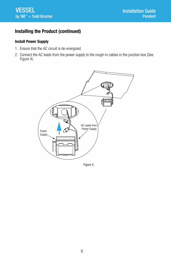
Installing the Product (continued)
Install Power Supply
1. Ensure that the AC circuit is de-energized.
2. Connect the AC leads from the power supply to the rough-in cables in the junction box (See Figure 4).
Power
Supply
Figure 4.
AC Leads from
Power Supply

7
Installing the Product (continued)
Adjust Power Cable to Desired Length
1. Loosen the set screw securing the strain relief bushing, then adjust the length of the power cable between the universal crossbar and the fixture as desired (See Figure 5).
2. Tighten the set screw, ensuring that the split in the strain relief bushing is NOT aligned with the set screw.
3. Trim the end of the power cable above the universal crossbar and strip the leads.l
Strain Relief
Bushing
Loosen Set Screw
Figure 5.
Adjust Cable
Length

8
VESSEL Installation GuidePendantby 3M + Todd Bracher™
Installing the Product (continued)
Connect the Power Cable to the Power Supply
• Connect the DC leads from the power supply to the leads from the power cable (See Figure 6). Ensure that the DC leads are connected red to red (positive) and black to black (negative).
DC Lead
Connections
Figure 6.

9
Installing the Product (continued)
Attach the Universal Crossbar to the Junction Box
• Attach the universal crossbar to the junction box using the screws supplied with the junction box (See Figure 7).
Figure 7. Junction Box Screws

10
VESSEL Installation GuidePendantby 3M + Todd Bracher™
Installing the Product (continued)
Install the Canopy Plate
1. Adjust the stand-off screws. The canopy plate should be flush with the ceiling when installed.
2. Install the canopy plate on the stand-off screws, turning the plate as shown (See Figure 8).
Figure 8.
Stand-off Screw
and Receiver
Canopy Plate
11
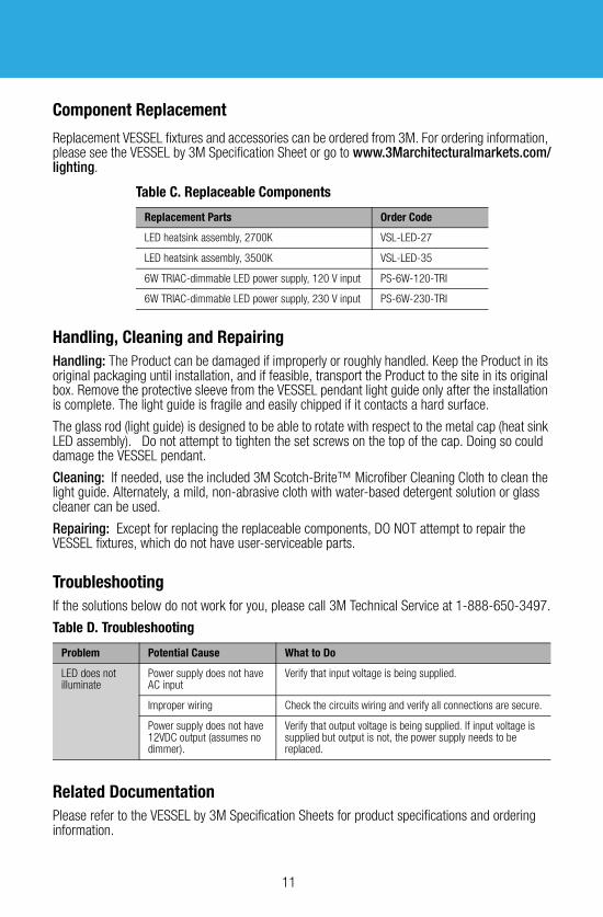
Component Replacement
Replacement VESSEL fixtures and accessories can be ordered from 3M. For ordering information, please see the VESSEL by 3M Specification Sheet or go to www.3Marchitecturalmarkets.com/lighting.
Handling, Cleaning and Repairing
Handling: The Product can be damaged if improperly or roughly handled. Keep the Product in its original packaging until installation, and if feasible, transport the Product to the site in its original box. Remove the protective sleeve from the VESSEL pendant light guide only after the installation is complete. The light guide is fragile and easily chipped if it contacts a hard surface.
The glass rod (light guide) is designed to be able to rotate with respect to the metal cap (heat sink LED assembly). Do not attempt to tighten the set screws on the top of the cap. Doing so could damage the VESSEL pendant.
Cleaning: If needed, use the included 3M Scotch-Brite™ Microfiber Cleaning Cloth to clean the light guide. Alternately, a mild, non-abrasive cloth with water-based detergent solution or glass cleaner can be used.
Repairing: Except for replacing the replaceable components, DO NOT attempt to repair the VESSEL fixtures, which do not have user-serviceable parts.
Troubleshooting
If the solutions below do not work for you, please call 3M Technical Service at 1-888-650-3497.
Related Documentation
Please refer to the VESSEL by 3M Specification Sheets for product specifications and ordering information.
Table D. Troubleshooting
Problem Potential Cause What to Do
LED does not illuminate
Power supply does not have AC input
Verify that input voltage is being supplied.
Improper wiring Check the circuits wiring and verify all connections are secure.
Power supply does not have 12VDC output (assumes no dimmer).
Verify that output voltage is being supplied. If input voltage is supplied but output is not, the power supply needs to be replaced.
Table C. Replaceable Components
Replacement Parts Order Code
LED heatsink assembly, 2700K VSL-LED-27
LED heatsink assembly, 3500K VSL-LED-35
6W TRIAC-dimmable LED power supply, 120 V input PS-6W-120-TRI
6W TRIAC-dimmable LED power supply, 230 V input PS-6W-230-TRI

3M Architectural Markets
3M U.S.3M Center
Building 22012E-04
St. Paul, MN 551441000
18886503497
3MArchitecturalMarkets.com
3M Canada1840 Oxford St E
London, ON N5V 3R6
1-800-265-1840
3M and ScotchBrite are trademarks of 3M Company. © 3M 2014. All rights reserved. Please recycle.
Part number: 98-0406-0092-0, Revision A, June 2014
VESSEL Installation GuidePendantby 3M + Todd Bracher™
WARRANTY
Product
VESSEL by 3M + Todd Bracher (the “Product”) is a decorative LED luminaire for dry interior use (the “Application”).
Limited Warranty
1. When used in the Application, 3M warrants to the party who purchased the Product directly from 3M (the “Buyer”) that the Product will be free from defects in material and workmanship (the “3M Warranty”) for a period of five years (“War-ranty Period”), which will begin on the earlier of: (a) Product installation date; or (b) three months after 3M's Product shipment date.
2. For Buyer’s convenience, 3M may provide a Specification Sheet, other engineering or technical information, recom-mendations, installation instructions, and other Product-related information or materials (all collectively referred to as “Product Information”), but 3M does not warrant any Product Information.
3. The 3M Warranty is contingent on the Product being stored, wired, installed, maintained, and used only as 3M recom-mends in all Product Information and in this Warranty Document. Also, 3M has no obligation under the 3M Warranty as to Product that has been: (a) modified or altered in any manner; (b) damaged through contact with a person or thing, misuse, accident, vandalism, neglect, or other action by anyone other than 3M; (c) affected by environmental condi-tions, such as power fluctuations, improper power supply, or activity by animals or insects; or (d) used not in compli-ance with all applicable standards and electrical codes.
4. EXCEPT TO THE EXTENT PROHIBITED BY APPLICABLE LAW, THE 3M WARRANTY IS MADE IN LIEU OF ALL OTHER WARRANTIES, RIGHTS OR CONDITIONS, EXPRESS OR IMPLIED, STATUTORY OR OTHERWISE, INCLUDING, BUT NOT LIMITED TO, ANY IMPLIED WARRANTY OF MERCHANTABILITY, SATISFACTORY QUALITY, FITNESS FOR A PARTICULAR PURPOSE AND THOSE ARISING FROM A COURSE OF DEALING, CUSTOM OR USAGE OF TRADE. BUYER IS RESPON-SIBLE FOR DETERMINING IF A PRODUCT IS SUITABLE FOR ITS PARTICULAR PURPOSE AND ITS INSTALLATION.
Limited Remedy
3M must receive any 3M Warranty claim in writing by the earlier of: (a) applicable Warranty Period’s expiration date; or (b) fourteen business days after Buyer’s discovery of that 3M Warranty claim. If the Product is proven not to have met the 3M Warranty during the applicable Warranty Period, then BUYER’S EXCLUSIVE REMEDY AND 3M’S SOLE OBLIGATION, WILL BE AT 3M’S OPTION, TO REPAIR OR REPLACE THAT PRODUCT QUANTITY OR REFUND THE APPLICABLE PURCHASE PRICE.
Limitation of Liability
3M WILL NOT UNDER ANY CIRCUMSTANCES BE LIABLE TO BUYER FOR DIRECT (other than the Limited Remedy above), SPECIAL, INCIDENTAL, INDIRECT OR CONSEQUENTIAL DAMAGES (INCLUDING, WITHOUT LIMITATION, LOSS OF PROFITS) IN ANY WAY RELATED TO A PRODUCT, THIS WARRANTY DOCUMENT, OR PRODUCT INFORMATION, REGARDLESS OF THE LEGAL OR EQUITABLE THEORY ON WHICH SUCH DAMAGES ARE SOUGHT.