VersaFlow Coriolis 100 Mass Flow Sensor …eneric.net/Honeywell/Technical-data/VersaFlow...
84
VersaFlow Coriolis 100 Mass Flow Sensor Specifications 34-VF-03-09 May 2011 The Universal Solution for the Process Industry VERSAFLOW is the only sensor for mass flow in its class with secondary pressure containment as standard. VERSAFLOW reliably measures mass flow of liquids and gases, concentration and density of liquids. Highlights Innovative twin measuring tube Easily drained and easy to clean Insensitive of installation and external factors Long working life Optimized flow divider for minimum pressure loss High accuracy with best price-performance ratio Modular electronics concept: electronics and sensor easy to replace Data redundancy: accurate plug & play replacement of electronics Industries Wastewater Chemical Food & Beverage Paper & Pulp Petrochemistry Pharmaceutical Water Figure 1 – VersaFlow Mass Flow Sensor Applications Suitable for all standard applications up to 130°C / 266°F With hygienic type process connections for food and pharmaceutical applications
Transcript of VersaFlow Coriolis 100 Mass Flow Sensor …eneric.net/Honeywell/Technical-data/VersaFlow...

VersaFlow Coriolis 100 Mass Flow Sensor Specifications 34-VF-03-09 May 2011
The Universal Solution for the Process Industry VERSAFLOW is the only sensor for mass flow in its class with secondary pressure containment as standard. VERSAFLOW reliably measures mass flow of liquids and gases, concentration and density of liquids.
Highlights Innovative twin measuring tube
Easily drained and easy to clean
Insensitive of installation and external factors
Long working life
Optimized flow divider for minimum pressure loss
High accuracy with best price-performance ratio
Modular electronics concept: electronics and sensor easy to replace
Data redundancy: accurate plug & play replacement of electronics
Industries Wastewater
Chemical
Food & Beverage
Paper & Pulp
Petrochemistry
Pharmaceutical
Water
Figure 1 – VersaFlow Mass Flow Sensor
Applications Suitable for all standard applications up to 130°C /
266°F
With hygienic type process connections for food and pharmaceutical applications

VersaFlow Coriolis 100 Mass Flow Sensor 2
Mass Flowmeter Product Family All meters consist of a sensor and a converter, which may be mounted integral to the sensor, or remotely, either with a field mount kit, a wall mount housing or a 19" rack mount module. A sensor mount converter (TWC 010) with a Modbus® output only is also possible for OEM manufacturers or where the user does not require a converter with analogue outputs.
Converter: Common hardware for All Converters Makes Spares Holding Simpler
1. TWC 9000 C: Compact or integrally mounted on sensor
2. TWC 9000 F: Field mount up to 300 m / 1000 ft from sensor
3. TWC 9000 W: Wall mount for non-hazardous areas
4. TWC 9000 R: 19" Rack mount module for control room installation
5. TWC 010: Sensor electronics with Modbus output
Sensor: Sensors for Any Applications
1. VersaFlow Coriolis 100: The general purpose solution for the process industry 2. VersaFlow Coriolis 1000:The optimum solution for chemical, food & beverage and pharmaceutical industry 3. VersaFlow Coriolis 200: Large diameter meter suitable for custody transfer measurement

VersaFlow Coriolis 100 Mass Flow Sensor 3
Technical Data Operating Data
Size S15 S25 S40 S50
Flow Rate
Maximum flow rate [kg/h] 6500 27000 80000 170000
Maximum flow rate [lbs/min] 240 990 2935 6235
Accuracy
Accuracy, liquid ±0.15% of actual measured flow rate
Accuracy, gas ±0.50% of actual measured flow rate
Repeatability Better than 0.05% plus zero stability (includes the combined effects of repeatability, linearity and hysteresis)
Zero stability ±0.01% of nominal flow rate with respective sensor size
Reference Conditions
Product Water
Temperature 20°C/68°F
Operating pressure 1 barrel. / 14.5 psig
Density
Measuring range 400...2500 kg/m3 / 25...155 lbs/ft3
Accuracy ±2 kg/m3 / ±0.13 lbs/ft3 (S15: ±5 kg/m3 / ±0.33 lbs/ft3)
Accuracy (on-site calibration) ±0.5 kg/m3 / ±0.033 lbs/ft3
Temperature
Measuring range -40...+130°C / -40...+266°F
Accuracy ±1°C / ±1.8°F
Materials
Measuring tube Stainless steel UNS S31803 (1.4462)
Spigot Stainless steel 316 / 316L (CF3M / 1.4409) dual certified
Flanges Stainless steel 316 / 316L (1.4401 / 1.4404) dual certified
Outer cylinder (secondary pressure containment)
Stainless steel 304 / 304L (1.4301 /1.4307) dual certified (Optional Stainless Steel 316 / 316L (1.4401 / 1.4404) dual certified)
Junction Box – remote version Die cast Aluminum (polyurethane coating) Optional Stainless Steel 316L (1.4401)
Heating jacket version
Heating jacket Stainless Steel 316L (1.4404) (The outer cylinder is in contact with the heating medium)

VersaFlow Coriolis 100 Mass Flow Sensor 4
Nominal Pressure at 20°C or 68°F
Measuring Tube -1…100 bar g/ -14.5 …1450 psig
Outer Cylinder
Non PED/CRN Approved Typical burst pressure > 100 barg. / 1450 psig
PED/CRN Approved secondary containment
-1...63 barg. / -14.5...910 psig
PED approved secondary containment -1...100 barg. / -14.5...1450 psig
Approvals and Certifications
Mechanical:
Electromagnetic compatibility (EMC) acc. to CE
Namur NE 21/5.95 89/336/EEC (EMC) 72/73/EEC (Low Voltage Directive)
Protection category (acc. to EN 60529) IP 67; NEMA 4X
European Pressure Equipment Directive PED 97-23 EC (acc. to AD 2000 Regelwerk)
Factory Mutual / CSA Class I, Div 1 groups A, B, C, D Class II, Div 1 groups E, F, G Class III, Div 1 hazardous areas Class I, Div 2 groups A, B, C, D Class II, Div 2 groups F, G Class III, Div 2 hazardous areas
ANSI / CSA (Dual Seal) 12.27.901-2003
Hygienic 3A 28-03
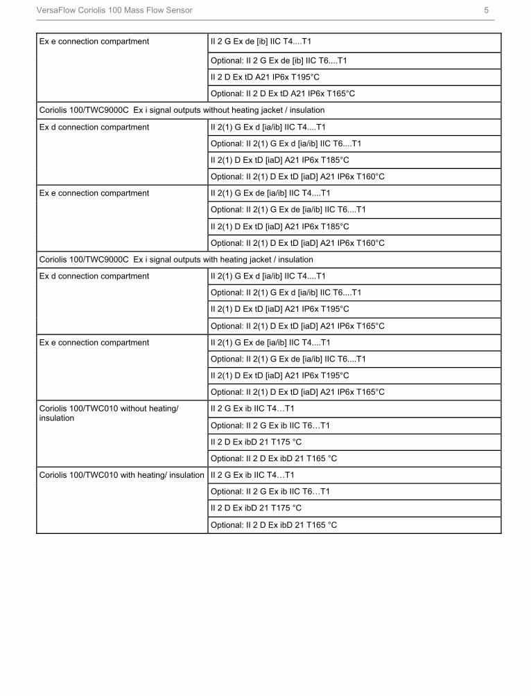
ATEX (acc. 94/9/EC)
Coriolis 100/TWC9000C non Ex i Signal outputs without heating jacket / insulation
II 2 G Ex d [ib] IIC T4....T1
Optional: II 2 G Ex d [ib] IIC T6....T1
II 2 D Ex tD A21 IP6x T185°C
Ex d connection compartment
Optional: II 2 D Ex tD A21 IP6x T160°C
II 2 G Ex de [ib] IIC T4....T1
Optional: II 2 G Ex de [ib] IIC T6....T1
II 2 D Ex tD A21 IP6x T185°C
Ex e connection compartment
Optional: II 2 D Ex tD A21 IP6x T160°C
Coriolis 100/TWC9000C non Ex i signal outputs with heating jacket / insulation
II 2 G Ex d [ib] IIC T4....T1
Optional: II 2 G Ex d [ib] IIC T6....T1
II 2 D Ex tD A21 IP6x T195°C
Ex d connection compartment
Optional: II 2 D Ex tD A21 IP6x T165°C
VersaFlow Coriolis 100 Mass Flow Sensor 5
II 2 G Ex de [ib] IIC T4....T1
Optional: II 2 G Ex de [ib] IIC T6....T1
II 2 D Ex tD A21 IP6x T195°C
Ex e connection compartment
Optional: II 2 D Ex tD A21 IP6x T165°C
Coriolis 100/TWC9000C Ex i signal outputs without heating jacket / insulation
II 2(1) G Ex d [ia/ib] IIC T4....T1
Optional: II 2(1) G Ex d [ia/ib] IIC T6....T1
II 2(1) D Ex tD [iaD] A21 IP6x T185°C
Ex d connection compartment
Optional: II 2(1) D Ex tD [iaD] A21 IP6x T160°C
II 2(1) G Ex de [ia/ib] IIC T4....T1
Optional: II 2(1) G Ex de [ia/ib] IIC T6....T1
II 2(1) D Ex tD [iaD] A21 IP6x T185°C
Ex e connection compartment
Optional: II 2(1) D Ex tD [iaD] A21 IP6x T160°C
Coriolis 100/TWC9000C Ex i signal outputs with heating jacket / insulation
II 2(1) G Ex d [ia/ib] IIC T4....T1
Optional: II 2(1) G Ex d [ia/ib] IIC T6....T1
II 2(1) D Ex tD [iaD] A21 IP6x T195°C
Ex d connection compartment
Optional: II 2(1) D Ex tD [iaD] A21 IP6x T165°C
II 2(1) G Ex de [ia/ib] IIC T4....T1
Optional: II 2(1) G Ex de [ia/ib] IIC T6....T1
II 2(1) D Ex tD [iaD] A21 IP6x T195°C
Ex e connection compartment
Optional: II 2(1) D Ex tD [iaD] A21 IP6x T165°C
II 2 G Ex ib IIC T4…T1
Optional: II 2 G Ex ib IIC T6…T1
II 2 D Ex ibD 21 T175 °C
Coriolis 100/TWC010 without heating/ insulation
Optional: II 2 D Ex ibD 21 T165 °C
II 2 G Ex ib IIC T4…T1
Optional: II 2 G Ex ib IIC T6…T1
II 2 D Ex ibD 21 T175 °C
Coriolis 100/TWC010 with heating/ insulation
Optional: II 2 D Ex ibD 21 T165 °C

VersaFlow Coriolis 100 Mass Flow Sensor 6
Approvals and Certifications continued ATEX (acc. 94/9/EC) temperature limits (standard) Ambient temp.
Tamb °C Max. medium temp. Tm °C
Temp. class
Max. surface temp. °C
89 T4 T130 Coriolis 100/TWC9000 or TWC010 - with or without heating jacket / insulation
65
130 T3 - T1 T175
70 T4 T130 50
130 T3 - T1 T185
60 60 T 4 - T1 T125
Coriolis 100/TWC9000 - aluminium converter housing - no heating jacket / insulation
65 (1) 65 T4 - T1 T130
65 T4 T130 40
130 T3 - T1 T195
65 T4 T130 50
100 T3 - T1 T165
60 60 T4 - T1 T125
Coriolis 100/TWC9000 - aluminium converter housing - heating jacket / insulation
65 (1) 65 T4 - T1 T130
70 T4 T130 50
130 T3 - T1 T185
Coriolis 100/TWC9000 - SS converter housing - no heating jacket / insulation
55 55 T4 - T1 T120
65 T4 T130 40
120 T3 - T1 T185
65 T4 T130 50
75 T3 - T1 T140
Coriolis 100/TWC9000 - SS converter housing - heating jacket / insulation
55 55 T4 - T1 T120
45 T6 T180
60 T5 T95
95 T4 T130
Coriolis 100/TWC9000/TWC010 T6 - with or without heating jacket / insulation
40
130 T3-T1 T165
45 T6 T80
60 T5 T95
100 T4 T130
40
130 T3-T1 T155
60 T5 T95
100 T4 T130
50
130 T3-T1 T160
60 60 T 4-T1 T95
Coriolis 100/TWC9000/T6 - aluminium converter housing - no heating jacket / insulation OPTIMASS 1000
65(1) 65 T4-T1 T100 1 Depending on I/O option. Please call for more information.

VersaFlow Coriolis 100 Mass Flow Sensor 7
ATEX (acc. 94/9/EC) temperature limits (standard) Ambient temp. Tamb °C
Max. medium temp. Tm °C
Temp. class
Max. surface temp. °C
45 T6 T80
60 T5 T95
100 T4 T130
40
130 T3-T1 T155
60 T5 T95
100 T4 T130
50
130 T3-T1 T160
Coriolis 100/TWC9000/T6 - Stainless Steel converter housing - no heating jacket / insulation
55 55 T4-T1 T95
45 T6 T80
60 T5 T95
95 T4 T130
40
120 T3-T1 T155
60 T5 T95 50
75 T4-T1 T110
Coriolis 100/TWC9000 T6 - Stainless Steel converter housing - heating jacket / insulation
55 55 T4-T1 T130
NEPSI (with TWC9000C/F, TWC 010) Exdeib(ia)II C T1...T6, Exdib(ia)II C T1...T6
Temperature
Process temperature - flanged connections -40...+130°C / -40...+266°F
Process temperature - hygienic connections -20...+130°C / -4...+266°F
Ambient temperature - compact version 40...+60°C / -40...+140°F for Aluminum converter (Extended temperature range: +65°C / +149°F for some I/O options. For more information contact manufacturer.) -40...+55°C / -40…+130°F for Stainless Steel converter
Ambient temperature - remote version -40...+65°C / -40...+149°F
Process Effects on the Sensor
Temperature 0.001% per 1°C / 0.00055% per 1°F
Pressure 0.00012% of the max flow rate per 1 barrel / 0.0000083% of the max flow rate per 1 psig

VersaFlow Coriolis 100 Mass Flow Sensor 8
Dimensions and Weights Flanged Versions
Meter Weights (all flanges) Weight – kg (lbs)
S15 S25 S40 S50
Aluminium (compact) 13.5 (30) 16.5 (36.3) 29.5 (65) 57.5 (127) Stainless Steel (compact) 18.8 (41) 21.8 (48) 34.8 (77) 62.8 (138
Aluminium (remote) 11.5 (25) 14.5 (32) 25.5 (56) 51.5 (113) Stainless Steel (remote) 12.4 (27) 15.4 (33.8) 26.4 (58) 52.4 (115)
Measuring Tube Stainless Steel
Dimensions – mm (inches)
S15 S25 S40 S50
A 101.6 (4) 114.3 (4.5) 168.3 (6.6) 219.1 (8.6) C1 (compact) 311 (12.2) 317 (12.5) 344 (13.5) 370 (14.6) C2 (remote) 231 (9) 237 (9.3) 264 (10.4) 290 (11.4) D 160 (6.3) E 60 (2.4) F 123.5 (2.4) G 137 (5.4) H 98.5 (3.9)

VersaFlow Coriolis 100 Mass Flow Sensor 9
Flange Connections
Dimension B [mm] S15 S25 S40 S50
PN40 DN15 498 - - - DN25 503 531 - - DN40 513 541 706 - DN50 - 547 712 862 DN80 - - 832 882 DN100 - - - 896 PN63 DN50 - - 740 890 DN80 - - - 910 PN100 DN15 513 - - - DN25 538 567 - - DN40 - 575 740 - DN50 - - 752 902 DN80 - - - 922
ASME 150 ½¨ 518 - - - ¾¨ 528 - - - 1¨ 534 563 - - 1½¨ - 575 740 - 2¨ - 579 744 894 3¨ - - 756 906 4¨ - - - 920 ASME 300 ½¨ 528 - - - ¾¨ 538 - - - 1¨ 546 575 - - 1½¨ - 589 754 2¨ - - 756 906 3¨ - - - 926 ASME 600 ½¨ 541 - - - ¾¨ 550 - - - 1¨ 558 589 - - 1½¨ - 603 770 - 2¨ - - 774 926 3¨ - - - 944 JIS 10K 50A - - 712 862 80A - - - 882 JIS 20K 15A 498 - - - 25A 503 531 - - 40A - 541 706 - 50A - - 712 862 80A - - - 882

VersaFlow Coriolis 100 Mass Flow Sensor 10
Dimension B [inches]
S15 S25 S40 S50 PN40 DN15 19.6 - - - DN25 19.8 21 - - DN40 20.2 21.3 27.8 - DN50 - 21.5 28 33.9 DN80 - - 28.8 34.7 DN100 - - - 35.3 PN63 DN50 - - 29 35 DN80 - - - 35.8 PN100 DN15 20.2 - - - DN25 21.2 22.3 - - DN40 - 22.6 29 - DN50 - - 29.6 35.5 DN80 - - - 36.3
ASME 150 ½¨ 20.4 - - - ¾¨ 20.8 - - - 1¨ 21 22.2 - - 1½¨ - 22.5 29.1 2¨ - 22.8 29.3 35.2 3¨ - - 29.8 35.7 4¨ - - - 36.2 ASME 300 ½¨ 20.8 - - - ¾¨ 21.2 - - - 1¨ 21.5 22.6 - - 1½¨ - 23.2 29.7 2¨ - - 29.8 35.7 3¨ - - - 36.4 ASME 600 ½¨ 21.3 - - - ¾¨ 21.6 - - - 1¨ 22 23.2 - - 1½¨ - 23.7 30.3 - 2¨ - - 30.5 36.4 3¨ - - - 37.2 JIS 10K 50A - - 28 33.9 80A - - - 34.7 JIS 20K 15A 19.6 - - - 25A 19.8 20.9 - - 40A - 21.3 27.8 - 50A - - 28 33.9 80A - - - 34.7

VersaFlow Coriolis 100 Mass Flow Sensor 11
Hygienic versions
Hygienic Connections: All Welded Versions
Dimension B (mm) S15 S25 S40 S50
Tri-clover 1" 487 1½" 534 2" 691 3" 832
Dimension B (mm)
S15 S25 S40 S50
Tri-clamp DIN 32676
DN10 DN15 DN25 468 DN40 515 DN50 677 DN80 836
Dimension B (mm)
S15 S25 S40 S50
Tri-clamp ISO 2852 1" 473 1½" 502 2" 667 3" 817

VersaFlow Coriolis 100 Mass Flow Sensor 12
Dimension B (mm) S15 S25 S40 S50
DIN 11864-2 form A DN25 505 DN40 562 DN50 724 DN80 896
Dimension B (inches)
S15 S25 S40 S50
Tri-clover 1" 19.2 1½" 21 2" 27.2 3" 32.7
Dimension B (inches)
S15 S25 S40 S50
Tri-clamp DIN 32676 DN10 DN15 DN25 18.4 DN40 20.3 DN50 26.6 DN80 32.9
Dimension B (inches)
S15 S25 S40 S50
Tri-clamp ISO 2852 1" 18.6 1½" 19.8 2" 26.3 3" 32.2
Dimension B (inches)
S15 S25 S40 S50
DIN 11864-2 form A DN25 19.9 DN40 22.2 DN50 28.5 DN80 35.3

VersaFlow Coriolis 100 Mass Flow Sensor 13
Hygienic Connections: Adapter Versions (male thread)
Dimension B (mm) S15 S25 S40 S50
Male thread DIN 11851
DN25 483 DN40 538 DN50 704 DN80 870
Dimension B (mm)
S15 S25 S40 S50
Male thread SMS 1" 474 1½" 537 2" 694 3" 837
Dimension B (mm)
S15 S25 S40 S50
Male thread IDF/ISS 1" 487 1½" 534 2" 691 3" 832

VersaFlow Coriolis 100 Mass Flow Sensor 14
Dimension B (mm) S15 S25 S40 S50
Male thread RJT 1" 498 1½" 545 2" 702 3" 843
Dimension B (inches)
S15 S25 S40 S50
Male thread DIN 11851
DN25 19 DN40 21.2 DN50 27.7 DN80 34.2
Dimension B (inches)
S15 S25 S40 S50
Male thread SMS 1" 18.7 1½" 21.1 2" 27.3 3" 32.9
Dimension B (inches)
S15 S25 S40 S50
Male thread IDF/ISS 1" 19.2 1½" 21 2" 27.2 3" 32.7
Dimension B (inches)
S15 S25 S40 S50
Male thread RJT 1" 19.6 1½" 21.4 2" 27.6 3" 33.2

VersaFlow Coriolis 100 Mass Flow Sensor 15
Heating Jacket Version
Dimensions – (mm)
S15 S25 S40 S50
Heating Conn Size 12 mm (ERMETO) 25
A 115 ±1 142 ±1 206 ±1 254 ±1
B 51 55 90 105
C 20 26
Dimensions – (inches)
S15 S25 S40 S50
Heating Conn Size ½" (NPTF) 1
A 4.5 ±0.04 5.6 ±0.04 8.1 ±0.04 10 ±0.04 B 2.0 2.2 3.5 4.1
C 0.8 1.0

VersaFlow Coriolis 100 Mass Flow Sensor 16
Purge Port Option
Dimensions – (mm)
S15 S25 S40 S50
A 30 ±1.0 65 ±1.0 B 30 ±1.0 65 ±1.0
Dimensions – (inches)
S15 S25 S40 S50
A 1.2 ±0.04 2.5 ±0.04 B 1.2 ±0.04 2.5 ±0.04

VersaFlow Coriolis 100 Mass Flow Sensor 17
Measuring Accuracy
X flow rate [%]
Y measuring error [%]
Measuring error
The measuring error is obtained from the combined effects of accuracy and zero stability.
Reference conditions
Product: Water Temperature: +20°C / +68°F Operating pressure: 1 barg / 14.5 psig
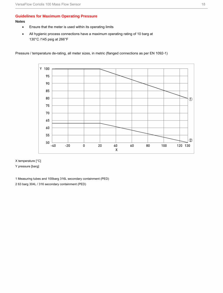
VersaFlow Coriolis 100 Mass Flow Sensor 18
Guidelines for Maximum Operating Pressure Notes
Ensure that the meter is used within its operating limits
All hygienic process connections have a maximum operating rating of 10 barg at 130°C /145 psig at 266°F
Pressure / temperature de-rating, all meter sizes, in metric (flanged connections as per EN 1092-1)
X temperature [°C]
Y pressure [barg]
1 Measuring tubes and 100barg 316L secondary containment (PED)
2 63 barg 304L / 316 secondary containment (PED)

VersaFlow Coriolis 100 Mass Flow Sensor 19
Pressure / temperature de-rating, all meter sizes, in imperial (flanged connections as per ASME B16.5)
X temperature [°F]
Y pressure [psig]
1 Measuring tubes S15 / S25 (CRN)
2 Measuring tubes S40 (CRN)
3 Measuring tubes S50 (CRN)
4 Secondary containment 304L / 316L (CRN)
Flanges
DIN flange ratings are based on EN 1092-1 2007 table G.4.1 material group 14EO
ASME flange ratings are based on ASME B16.5 2003 table 2 material group 2.2
JIS flange ratings are based on JIS 2220: 2001 table 1 division 1 material group 022a
Notes
The maximum operating pressure will be either the flange rating or the measuring tube rating, WHICHEVER IS THE LOWER!
The manufacturer recommends that the seals are replaced at regular intervals. This will maintain the hygienic integrity of the connection.

VersaFlow Coriolis 100 Mass Flow Sensor 20
For More Information
Learn more about how Honeywell’s VersaFlow Coriolis 100 Mass Flow Sensor can reliably measure mass flow of liquids and gases, visit our website www.honeywell.com/ps/hfs or contact your Honeywell account manager. Honeywell Process Solutions
1860 West Rose Garden Lane Phoenix, Arizona 85027 Tel: 1-800-423-9883 or 1-800-343-0228 www.honeywell.com/ps/hfs
Specifications are subject to change without notice.
34-VF-03-09 May 2011 © 2011 Honeywell International Inc.

VersaFlow Coriolis 1000 Mass Flow Sensor Specifications 34-VF-03-03 August 2011
The Superior Solution
The VersaFlow mass flow sensor is the only mass flow
sensor with a straight measuring tube that is available in
Stainless steel, Hastelloy®, Titanium or Tan0H1Htalum.
VersaFlow reliably measures mass flow, density, volume,
temperature, mass or volume concentration and solids
content.
Highlights
Single straight measuring tube
Secondary pressure containment
Low pressure loss
Easily drained and easy to clean
Choice of three different tube materials
Excellent zero stability
Low operating and installation costs
Rapid signal processing even with varying conditions
Modular/Plug & play electronics
Industries
Water and Wastewater
Mining & Building Materials
Chemical
Iron, Steel & Metal
Food & Beverage
Oil & Gas
Pulp & Paper
Petrochemical
Pharmaceutical
Figure 1 – VersaFlow Mass Flow Sensor
Applications
Viscous or shear-sensitive products
Products requiring low flow velocities
Inhomogeneous mixtures
Products with entrained solids or gas
Custody transfer
Loading and product transfer measurement
Slurries
Highly corrosive fluids

VersaFlow Coriolis 1000 Mass Flow Sensor 2
Compact version
1) Comprehensive diagnostic capabilities. 2) Standard flange and hygienic process connections available. 3) Standard electronics for all sensors with redundant storage of calibration and sensor data. 4) Modular electronics with a range of output options (see separate documentation for details).
1) Remote terminal box.

VersaFlow Coriolis 1000 Mass Flow Sensor 3
Features
Available as compact or remote. Low pressure loss - single straight tube design guarantees a low pressure drop across the meter. Self Draining. Easy to clean.
Connection options
A range of flanges up to ASME 600 / PN100. Supports a wide range of industry standard hygienic connections. Adaptable to suit customer's hygienic connections.
Heating jacket and purge port
Heating jacket option for use with temperature dependant products. Prevents solidification of process product. Purge port option for protection in the event of measuring tube failure. Allows hazardous chemicals to be drained away safely. Can also be used for the early detection of measuring tube failure where highly toxic chemicals are being
measured.

VersaFlow Coriolis 1000 Mass Flow Sensor 4
Converter: Common hardware for all converters makes spares holding simpler
1. TWC 9000 C: Compact or integrally mounted on sensor
2. TWC 9000 F: Field mount up to 300 m / 1000 ft from sensor
3. TWC 9000 W: Wall mount for non-hazardous areas
4. TWC 9000 R: 19" Rack mount module for control room installation
5. TWC 010: Sensor electronics with Modbus output
Mass Flowmeter Product Family
All meters consist of a sensor and a converter. The converter may be mounted integral to the sensor, or remotely, either with
a field mounting kit, a wall-mounted housing or a rack mounted housing. See specification 34-VF-03-04 for converter details.
Sensor: Sensors for any Applications
1. VersaFlow Coriolis 100: The general purpose solution for the process industry
2. VersaFlow Coriolis 1000: The optimum solution for chemical, food & beverage and pharmaceutical industry
3. VersaFlow Coriolis 200: Large diameter meter suitable for custody transfer measurement

VersaFlow Coriolis 1000 Mass Flow Sensor 5
Technical Data Operating Data
Size (Note 1) DN06 DN10 DN15 DN25 DN40 DN50 DN80
Flow Rate
Maximum flow rate [kg/h] 1230 3500 14600 44800 120000 234000 560000
Maximum flow rate [lbs/min] 35 100 400 1250 3300 6600 15800
Accuracy
Accuracy, liquid ±0.1% of actual measured flow rate
Accuracy, gas ±0.5% of actual measured flow rate
Repeatability Better than 0.05% plus zero stability (includes the combined effects of repeatability, linearity and hysteresis)
Zero stability-Titanium ±0.004% of nominal flow rate with respective sensor size
Zero stability-Stainless Steel/ Hastelloy/Tantalum
±0.015% of nominal flow rate with respective sensor size
Reference Conditions
Product Water
Temperature 20°C / 68°F
Operating pressure 1 barrel. / 14.5 psig
Density
Measuring range 400...2500 kg/m3 / 25...155 lbs/ft3
Accuracy ±2 kg/m3 / ±0.13 lbs/ft3
Accuracy (on-site calibration) ±0.5 kg/m3 / ±0.033 lbs/ft3
Hastelloy is a registered trademark of Haynes International.

VersaFlow Coriolis 1000 Mass Flow Sensor 6
Technical Data, Continued
Temperature Titanium Stainless Steel Hastelloy Tantalum
Measuring range -40… +150o C/
-40 …+302o F
0… +100o C/32 …+212o F
Extended range 0… +130o C/32 …+266o F on Stn. Stl sizes DN25..80, hygienic conn. only
Accuracy ±1°C / ±1.8°F
Materials Titanium Stainless Steel Hastelloy Tantalum
Measuring Tube/ raised face Titanium Stainless Steel Hastelloy Tantalum
Flanges Stainless Steel 316/316L (1.4401/1.4404) dual certified
Outer cylinder - standard Stainless Steel 304/304L (1.3401/1.4307) dual certified
Outer cylinder – optional n/a Stainless Steel 316/316L (1.4401/1.4404) dual certified
Optional Heating Jacket Stainless Steel 316L (1.4404)
Sensor Electronics Stainless Steel 316L (1.4409)
Junction Box – remote version Die cast Aluminum (polyurethane coating
Optional Stainless Steel 316L (1.4401)
Nominal Pressure at 20oC /68oF -1…100 barg/ -14.5 …1450 psig
-1…100 bar g/ -14.5 …1450 psig
Outer Cylinder Titanium Stainless Steel Hastelloy Tantalum
Non PED/CRN Approved Typical burst pressure > 100 barg. / 1450 psig
PED/CRN Approved secondary containment
-1...63 barg. / -14.5...910 psig
PED approved secondary containment
-1...100 barg. / -14.5...1450 psig

VersaFlow Coriolis 1000 Mass Flow Sensor 7
Operating Data
Size (Note 1) DN06 DN10 DN15 DN25 DN40 DN50 DN80
Titanium Stainless Steel, Hastelloy and Tantalum
Process Temperature -40… +150o C/
-40 …+302o F
0… +100o C/32 …+212o F
Extended range 0… +130o C/32 …+266o F on Stn. Stl sizes DN25..80, hygienic conn. Only
Ambient Temperature
Compact w/Aluminum Housing -40… +60o C/-40 …+140o F
Extended temperature range +65o C/+149o F for some I/O options. For more information contact Honeywell
Compact w/Stn. Stl. Housing -40… +55o C/-40 …+130o F
Remote versions -40… +65o C/-40 …+149o F
Process Effects on the Sensor
Temperature - Titanium 0.001% per 1°C / 0.055% per 1°F
Temperature – Stainless Steel/ Hastelloy/ Tantalum
0.004% per 1°C / 0.0022% per 1°F
Pressure 0.0011% of the max flow rate per 1 barrel. / 0.000076% of the max flow rate per 1 psig
Note 1: Hastelloy available Sizes DN10 … DN80. Tantalum available Sizes DN10… DN50
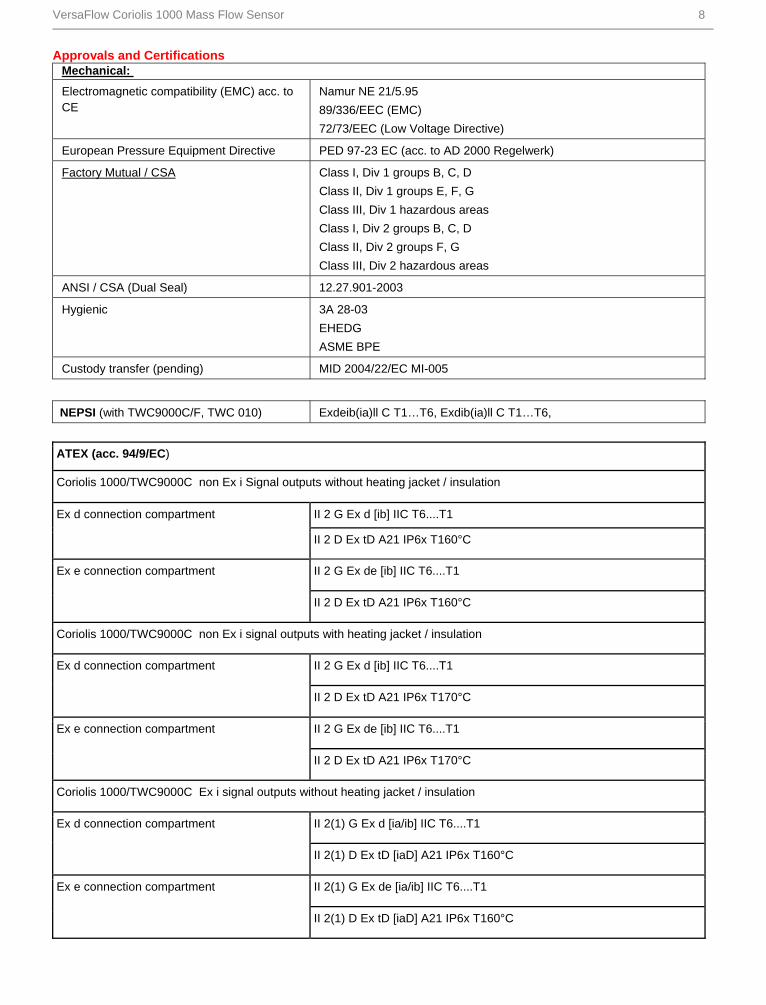
VersaFlow Coriolis 1000 Mass Flow Sensor 8
Approvals and Certifications Mechanical:
Electromagnetic compatibility (EMC) acc. to CE
Namur NE 21/5.95
89/336/EEC (EMC)
72/73/EEC (Low Voltage Directive)
European Pressure Equipment Directive PED 97-23 EC (acc. to AD 2000 Regelwerk)
Factory Mutual / CSA Class I, Div 1 groups B, C, D
Class II, Div 1 groups E, F, G
Class III, Div 1 hazardous areas
Class I, Div 2 groups B, C, D
Class II, Div 2 groups F, G
Class III, Div 2 hazardous areas
ANSI / CSA (Dual Seal) 12.27.901-2003
Hygienic 3A 28-03
EHEDG
ASME BPE
Custody transfer (pending) MID 2004/22/EC MI-005
NEPSI (with TWC9000C/F, TWC 010) Exdeib(ia)ll C T1…T6, Exdib(ia)ll C T1…T6,
ATEX (acc. 94/9/EC)
Coriolis 1000/TWC9000C non Ex i Signal outputs without heating jacket / insulation
II 2 G Ex d [ib] IIC T6....T1 Ex d connection compartment
II 2 D Ex tD A21 IP6x T160°C
II 2 G Ex de [ib] IIC T6....T1 Ex e connection compartment
II 2 D Ex tD A21 IP6x T160°C
Coriolis 1000/TWC9000C non Ex i signal outputs with heating jacket / insulation
II 2 G Ex d [ib] IIC T6....T1 Ex d connection compartment
II 2 D Ex tD A21 IP6x T170°C
II 2 G Ex de [ib] IIC T6....T1 Ex e connection compartment
II 2 D Ex tD A21 IP6x T170°C
Coriolis 1000/TWC9000C Ex i signal outputs without heating jacket / insulation
II 2(1) G Ex d [ia/ib] IIC T6....T1 Ex d connection compartment
II 2(1) D Ex tD [iaD] A21 IP6x T160°C
II 2(1) G Ex de [ia/ib] IIC T6....T1 Ex e connection compartment
II 2(1) D Ex tD [iaD] A21 IP6x T160°C

VersaFlow Coriolis 1000 Mass Flow Sensor 9
Coriolis 1000/TWC9000C Ex i signal outputs with heating jacket / insulation
II 2(1) G Ex d [ia/ib] IIC T6....T1 Ex d connection compartment
II 2(1) D Ex tD [iaD] A21 IP6x T170°C
II 2(1) G Ex de [ia/ib] IIC T6....T1 Ex e connection compartment
II 2(1) D Ex tD [iaD] A21 IP6x T170°C
II 2 G Ex ib IIC T6…T1 Coriolis 1000/TWC010 without heating/ insulation
II 2 D Ex ibD 21 T150 °C
II 2 G Ex ib IIC T6…T1 Coriolis 1000/TWC010 with heating/ insulation
II 2 D Ex ibD 21 T165 °C
ATEX (acc. 94/9/EC) temperature limits (standard)
Ambient temp. Tamb °C
Max. medium temp. Tm °C
Temp. class Max. surface temp. °C
70 T6 T80
90 T5 T95
130 T4 T130
40
150 T3-T1 T150
70 T6 T80
85 T5 T95
130 T4 T130
50
150 T3-T1 T150
85 T5 T95
130 T4 T130
Coriolis 1000/TWC9000 or TWC010 - without heating jacket / insulation
65
150 T3-T1 T150
65 T6 T80
80 T5 T95
115 T4 T130
40
150 T3-T1 T165
80 T5 T95
115 T4 T130
Coriolis 1000/TWC9000 or TWC010 - with heating jacket / insulation
65
150 T3-T1 T165

VersaFlow Coriolis 1000 Mass Flow Sensor 10
55 T6 T80
75 T5 T95
120 T4 T130
40
150 T3-T1 T160
75 T5 T95
115 T4 T130
50
150 T3-T1 T160
60 60 T4-T1 T85
Coriolis 1000/TWC9000 - aluminium converter housing - no heating jacket / insulation
65 65 T4-T1 T90
55 T6 T80
70 T5 T95
100 T4 T125
40
145 T3-T1 T170
70 T4 T95 50
100 T3-T1 T125
60 60 T4 - T1 T85
Coriolis 1000/TWC9000 - aluminium converter housing - heating jacket / insulation
65 65 T4 - T1 T90
ATEX (acc. 94/9/EC) temperature limits (standard)
Ambient temp. Tamb °C
Max. medium temp. Tm °C
Temp. class Max. surface temp. °C
55 T6 T80
75 T5 T95
120 T4 T130
40
150 T3-T1 T160
75 T5 T95
115 T4 T130
50
135 T3-T1 T160
Coriolis 1000/TWC9000 - SS converter housing - no heating jacket / insulation
55 55 T4-T1 T80
55 T6 T80
70 T5 T95
100 T4 T125
40
145 T3-T1 T170
70 T4 T95 50
35 T3-T1 T100
Coriolis 1000/TWC9000 - SS converter housing - heating jacket / insulation
55 55 T4-T2 T80

VersaFlow Coriolis 1000 Mass Flow Sensor 11
Dimensions and Weights
Flanged Versions
Meter weights for Titanium (T), Stainless Steel (S), Hastelloy (H) and Tantalum (A)
Weight – kg (lbs)
T/S 06 T/S/H/A 10 T/S/H/A 15 T/S/H/A 25 T/S/H/A 40 T/S/H/A 50 T/S/H 80
Aluminium (compact)
18.5 (40.7) 23 (50.6) 26 (57.2) 37 (81.4) 83 (182.6) 147 (323.4) 265 (583)
Stainless Steel (compact)
25.2 (55.4) 29.7 (65.3) 32.7 (71.9) 43.7 (96.1) 89.7 (197.3)
153.7 (338.1)
271.7 (597.7
Aluminium (remote)
15.7 (34.5) 20.2 (44.4) 23.2 (51) 34.2 (75.2) 80.2 (176.4)
144.2 (317.2)
262.2 (576.8)
Stainless Steel (remote)
16.5 (36.3) 21 (46.2) 24 (52.8) 35 (77) 81 (178.2) 145 (319) 263 (578.6)
Tantalum add n/a 2.3 (5.1) 2.7 (5.9) 4.5 (9.9) 9.2 (20.2) 15.1 (33.2 n/a
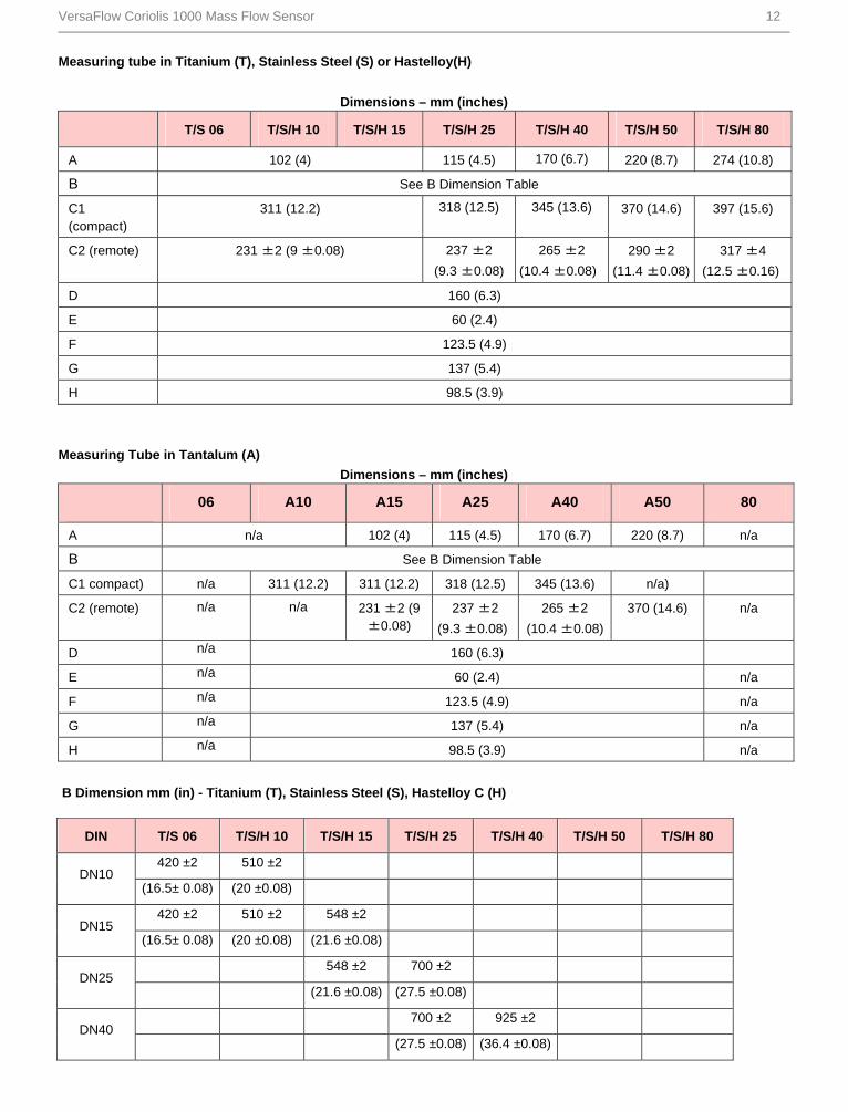
VersaFlow Coriolis 1000 Mass Flow Sensor 12
Measuring tube in Titanium (T), Stainless Steel (S) or Hastelloy(H)
Dimensions – mm (inches)
T/S 06 T/S/H 10 T/S/H 15 T/S/H 25 T/S/H 40 T/S/H 50 T/S/H 80
A 102 (4) 115 (4.5) 170 (6.7) 220 (8.7) 274 (10.8)
B See B Dimension Table
C1 (compact)
311 (12.2) 318 (12.5) 345 (13.6) 370 (14.6) 397 (15.6)
C2 (remote) 231 ±2 (9 ±0.08)
237 ±2
(9.3 ±0.08)
265 ±2
(10.4 ±0.08)
290 ±2
(11.4 ±0.08)
317 ±4
(12.5 ±0.16)
D 160 (6.3)
E 60 (2.4)
F 123.5 (4.9)
G 137 (5.4)
H 98.5 (3.9)
Measuring Tube in Tantalum (A)
Dimensions – mm (inches)
06 A10 A15 A25 A40 A50 80
A n/a 102 (4) 115 (4.5) 170 (6.7) 220 (8.7) n/a
B See B Dimension Table
C1 compact) n/a 311 (12.2) 311 (12.2) 318 (12.5) 345 (13.6) n/a)
C2 (remote) n/a n/a 231 ±2 (9 ±0.08)
237 ±2
(9.3 ±0.08)
265 ±2
(10.4 ±0.08)
370 (14.6) n/a
D n/a 160 (6.3)
E n/a 60 (2.4) n/a
F n/a 123.5 (4.9) n/a
G n/a 137 (5.4) n/a
H n/a 98.5 (3.9) n/a
B Dimension mm (in) - Titanium (T), Stainless Steel (S), Hastelloy C (H)
DIN T/S 06 T/S/H 10 T/S/H 15 T/S/H 25 T/S/H 40 T/S/H 50 T/S/H 80
420 ±2 510 ±2 DN10
(16.5± 0.08) (20 ±0.08)
420 ±2 510 ±2 548 ±2 DN15
(16.5± 0.08) (20 ±0.08) (21.6 ±0.08)
548 ±2 700 ±2 DN25
(21.6 ±0.08) (27.5 ±0.08)
700 ±2 925 ±2 DN40
(27.5 ±0.08) (36.4 ±0.08)

VersaFlow Coriolis 1000 Mass Flow Sensor 13
B Dimension mm (in) - Titanium (T), Stainless Steel (S), Hastelloy C (H)
DIN T/S 06 T/S/H 10 T/S/H 15 T/S/H 25 T/S/H 40 T/S/H 50 T/S/H 80
925 ±2 1101 ±2 DN50
(36.4 ±0.08) (43.3 ±0.08)
1101 ±2 1460 ±4 DN80
(43.3 ±0.08) (57.5 ±0.16)
1460 ±4 DN100
(57.5 ±0.16)
Torque/ Groove
T/S 06 T/S/H 10 T/S/H 15 T/S/H 25 T/S/H 40 T/S/H 50 T/S/H 80
428±2 518 ±2 DN10
(16.8± 0.08) (20.3 ±0.08)
428±2 518 ±2 556 ±2 DN15
(16.8± 0.08) (20.3 ±0.08) (21.9 ±0.08)
556 ±2 708 ±2 DN25
(21.9 ±0.08) (27.8 ±0.08)
708 ±2 933 ±2 DN40
(27.8 ±0.08) (36.7 ±0.08)
933 ±2 1109 ±2 DN50
(36.7 ±0.08) (43.6 ±0.08)
1109 ±2 1468 ±4 DN80
(43.6 ±0.08) (57.8 ±0.16)
1468 ±4 DN100
(57.8 ±0.16)
B Dimension mm (in) - Tantalum (A)
DIN A 06 A 10 A 15 A 25 A 40 A 50 A 80
557 ±2 DN10 NA
(21.9 ±0.08) NA
557 ±2 633 ±2 DN15 NA
(21.9 ±0.08) (24.9 ±0.08) NA
633 ±2 800 ±2 DN25 NA
(24.9 ±0.08) (31.5 ±0.08) NA
800 ±2 1075 ±2 DN40 NA
(31.5 ±0.08) (42.3 ±0.08) NA
1075 ±2 1281 ±2 DN50 NA
(42.3 ±0.08) (50.4 ±0.08) NA

VersaFlow Coriolis 1000 Mass Flow Sensor 14
DIN A 06 A 10 A 15 A 25 A 40 A 50 A 80
1281 ±2 DN80 NA
(50.4 ±0.08) NA
DN100 NA
NA
B Dimension mm (in) - Titanium (T), Stainless Steel (S), Hastelloy C (H)
ASME 150/ 300 lb
T/S 06 T/S/H 10 T/S/H 15 T/S/H 25 T/S/H 40 T/S/H 50 T/S/H 80
420 ±2 510 ±2 548 ±2 1/2"
(16.5± 0.08) (20 ±0.08) (21.6 ±0.08)
548 ±2 3/4"
(21.6 ±0.08)
548 ±2 700 ±2 1"
(21.6 ±0.08) (27.5 ±0.08)
700 ±2 925 ±2 1 1/2"
(27.5 ±0.08) (36.4 ±0.08)
925 ±2 1101 ±2 2"
(36.4 ±0.08) (43.3 ±0.08)
1101 ±2 1460 ±4 3"
(43.3 ±0.08) (57.5 ±0.16)
1460 ±4 4"
(57.5 ±0.16)
ASME 600 lb
T/S 06 T/S/H 10 T/S/H 15 T/S/H 25 T/S/H 40 T/S/H 50 T/S/H 80
428 ±2 518 ±2 556 ±2 1/2"
(16.8 ±0.08) (20.4±0.08) (21.9 ±0.08)
556 ±2 3/4"
(21.9 ±0.08)
556 ±2 708 ±2 1"
(21.9 ±0.08) (27.8 ±0.08)
708 ±2 933 ±2 1 1/2"
(27.8 ±0.08) (36.7±0.08)
933 ±2 1109 ±2 2"
(36.7±0.08) (43.7 ±0.08)
1109 ±2 1468 ±4 3"
(43.7 ±0.08) (57.8 ±0.16)
1468 ±4 4"
(57.8 ±0.16)

VersaFlow Coriolis 1000 Mass Flow Sensor 15
B Dimension mm (in) - Tantalum (A)
ASME 150/ 300 lb A 06 A 10 A 15 A 25 A 40 A 50 A 80
557 ±2 633 ±2 1/2" NA
(21.9 ±0.08) (24.9 ±0.08) NA
633 ±2 3/4" NA
(24.9 ±0.08) NA
633 ±2 800 ±2 1" NA
(24.9 ±0.08) (31.5 ±0.08) NA
800 ±2 1075 ±2 1 1/2" NA
(31.5 ±0.08) (42.3 ±0.08) NA
1075 ±2 1281 ±2 2" NA
(42.3 ±0.08) (50.4 ±0.08) NA
1281 ±2 3" NA
(50.4 ±0.08) NA
4" NA
NA

VersaFlow Coriolis 1000 Mass Flow Sensor 16
Hygienic Versions Titanium (T) and Stainless Steel (S)
Hygienic Connections: All Welded Versions
Dimension B [mm ±2] 06 10 15 25 40 50 80
Tri-clover
½" 480 558
¾" 596
1½" 816
2" 1043
3" 1305
4" 1527
Dimension B [mm ±2] 06 10 15 25 40 50 80
Tri-clamp DIN 32676
DN10 484 564
DN15 602
DN25 761
DN40 986
DN50 1168
DN80 1584

VersaFlow Coriolis 1000 Mass Flow Sensor 17
Hygienic connections: all welded versions
Dimension B [mm ±2]
06 10 15 25 40 50 80
Tri-clamp ISO 2852
1½" 816
2" 1043
3" 1305
4" 1527
Dimension B [mm ±2] 06 10 15 25 40 50 80
DIN 11864-2 form A
DN10 528
DN15 566
DN25 718
DN40 948
DN50 1124
DN80 1538
Dimension B [inches ±0.08] 06 10 15 25 40 50 80
Tri-clover
½" 18.9 22
¾" 23.5
1½" 32.1
2" 41
3" 51.4
4" 49.5
Dimension B [inches ±0.08] 06 10 15 25 40 50 80
Tri-clamp DIN 32676
DN10 19 22.2
DN15 23.7
DN25 30
DN40 38.8
DN50 46
DN80 62.4

VersaFlow Coriolis 1000 Mass Flow Sensor 18
Dimension B [inches ±0.08] 06 10 15 25 40 50 80
Tri-clamp ISO 2852
1½" 32.2
2" 41.1
3" 51.4
4" 60.1
Dimension B [inches ±0.08]
06 10 15 25 40 50 80
DIN 11864-2 form A
DN10 20.8
DN15 22.3
DN25 28.3
DN40 37.3
DN50 44.3
DN80 60.5

VersaFlow Coriolis 1000 Mass Flow Sensor 19
Hygienic Connections: Adapter Versions (male thread) Titanium (T) and Stainless Steel (S)
Dimension B [mm ±2] 10 15 25 40 50 80
Male thread DIN 11851
DN10 596
DN15 634
DN25 802
DN40 1040
DN50 1220
DN80 1658
Dimension B [mm ±2] 10 15 25 40 50 80
Male thread SMS
1" 665
1½" 852
2" 1074
3" 1360
Dimension B [mm ±2] 10 15 25 40 50 80
Male thread IDF/ISS
1" 664
1½" 854
2" 1076
3" 1354

VersaFlow Coriolis 1000 Mass Flow Sensor 20
Dimension B [mm ±2] 10 15 25 40 50 80
Male thread RJT
1" 676
1½" 866
2" 1088
3" 1366
Dimension B [inches ±0.08]
10 15 25 40 50 80
Male thread DIN 11851
DN10 23.5
DN15 25
DN25 31.6
DN40 41
DN50 48
DN80 65.3
Dimension B [inches ±0.08]
10 15 25 40 50 80
Male thread SMS
1" 26.2
1½" 33.5
2" 42.3
3" 53.5
Dimension B [inches ±0.08]
10 15 25 40 50 80
Male thread IDF/ISS
1" 26.1
1½" 33.6
2" 42.4
3" 53.3
Dimension B [inches ±0.08]
10 15 25 40 50 80
Male thread RJT
1" 26.6
1½" 34.1
2" 42.8
3" 53.8

VersaFlow Coriolis 1000 Mass Flow Sensor 21
Heating Jacket Version
Dimensions – mm (inches)
10 15 25 40 50 80
Heating connection size
12mm (ERMETO)
(½" (NPTF))
25mm (ERMETO)
(1" (NPTF))
A
115 ±1
(4.5 ±0.04)
142 ±1
(5.6 ±0.04)
206 ±1
(8.1 ±0.04)
254 ±1
(10 ±0.04)
305 ±1
(12 ±0.04)
Titanium B
36 ±1
(1.4 ±0.04)
51 ±1
(2 ±0.04)
100 ±1
(3.9 ±0.04)
90 ±1
(3.5 ±0.04)
175 ±1
(6.9 ±0.04)
385 ±1
(15.2 ±0.04) C
20
(0.8)
26 ±1
(1.0 ±0.04)
Stainless Steel & Hastelloy
B
-
51 ±1
(2 ±0.04)
55 ±1
(2.2 ±0.04)
90 ±1
(3.5 ±0.04)
100 ±2
(3.9 ±0.08)
200 ±2
(7.9 ±0.08)
C
-
20
(0.8)
26 ±1
(1.0 ±0.04)
Tantalum
B -
51 ±1
(2 ±0.04)
55 ±1
(2.2 ±0.04)
90 ±1
(3.5 ±0.04)
100 ±2
(3.9 ±0.08)
-
C -
20
(0.8)
26 ±1
(1.0 ±0.04)
-

VersaFlow Coriolis 1000 Mass Flow Sensor 22
Purge Port Option
Dimensions – mm (inches)
06 10 15 25 40 50 80
Titanium & Stainless Steel
A 65
(2.6)
30
(1.2)
65
(2.6)
B 30
(1.2)
65
(2.6)
Hastelloy
A -
30
(1.2)
65
(2.6)
B -
30
(1.2)
65
(2.6)
Tantalum
A -
-
30
(1.2)
65
(2.6)
-
B -
-
30
(1.2)
65
(2.6)
-

VersaFlow Coriolis 1000 Mass Flow Sensor 23
Measuring Accuracy
X flow rate [%]
Y measuring error [%]
1 Stainless Steel, Hastelloy and Tantalum
2 Titanium
Measuring error
The measuring error is obtained from the combined effects of accuracy and zero stability.
Reference conditions
Product: Water
Temperature: +20°C / +68°F
Operating pressure: 1 barg / 14.5 psig

VersaFlow Coriolis 1000 Mass Flow Sensor 24
Guidelines for Maximum Operating Pressure
Notes
Ensure that the meter is used within its operating limits
All hygienic process connections have a maximum operating rating of 10 barg at 130°C /145 psig at 266°F
Pressure / temperature de-rating for Titanium Gr 9 meters
(all meter sizes, with flanged connections as per EN 1092-1)
X temperature [°C]
Y pressure [barg]
1 Standard tube and outer cylinder 316L (100 barg PED option) with PN100 flanges (sizes DN06...25)
2 Standard tube and outer cylinder 316L (100 barg PED option) with PN100 flanges (sizes DN40...80)
3 DIN 2637 PN63 flanges
4 Outer cylinder 304 (63 barg PED / CRN option)
5 JIS 20K flanges
6 DIN 2635 PN40 flanges
7 JIS 10K flanges
8 Hygienic connections

VersaFlow Coriolis 1000 Mass Flow Sensor 25
Pressure / temperature de-rating for Titanium Gr 9 meters
(all meter sizes with flanged connections as per ASME B16.5)
X temperature [°F]
Y pressure [psig]
1 Standard tube and outer cylinder 316L (100 barg PED option) with ASME 600 lbs flanges (sizes DN06...25)
2 Standard tube and outer cylinder 316L (100 barg PED option) with ASME 600 lbs flanges (sizes DN40...80)
3 Outer cylinder 304 (63 barg PED / CRN option)
4 ASME 300 lbs
5 ASME 150 lbs
6 Hygienic connections

VersaFlow Coriolis 1000 Mass Flow Sensor 26
Pressure / temperature de-rating for Stainless Steel, Hastelloy C22 and Tantalum meters
(all meter sizes with flanged connections as per EN 1092-1)
X temperature [°C]
Y pressure [barg]
1 Standard tubes and outer cylinder 304 (all sizes) (63 barg PED / CRN option)
2 JIS 20K flanges
3 DIN 2635 PN40 flanges
4 JIS 10K flanges
5 Hygienic connections (extended temperature option, Stainless Steel only)

VersaFlow Coriolis 1000 Mass Flow Sensor 27
Pressure / temperature de-rating for Stainless Steel, Hastelloy C22 and Tantalum
meters(all meters with flanged connections as per ASME B16.5)
X temperature [°F]
Y pressure [psig]
1 Outer cylinder (all sizes) (63 barg PED / CRN option)
2 ASME 300 lbs
3 ASME 150 lbs
4 Hygienic connections (extended temperature option, Stainless Steel only)
Flanges
DIN flange ratings are based on EN 1092-1 2001 table 18, 1% proof stress material group 14EO
ASME flange ratings are based on ASME B16.5 2003 table 2 material group 2.2
JIS flange ratings are based on JIS 2220: 2001 table 1 division 1 material group 022a
Notes
The maximum operating pressure will be either the flange rating or the measuring tube rating, WHICHEVER IS THE
LOWER!
The manufacturer recommends that the seals are replaced at regular intervals. This will maintain the hygienic integrity of
the connection.

VersaFlow Coriolis 1000 Mass Flow Sensor 28
For More Information
Learn more about how Honeywell’s VersaFlow Coriolis
1000 Mass Flow Sensor can provide rapid signal
processing even with varying conditions, visit our website
www.honeywell.com/ps/hfs or contact your Honeywell
account manager.
Honeywell Process Solutions
1860 West Rose Garden Lane
Phoenix, Arizona 85027
Tel: 1-800-423-9883 or 1-800-343-0228 www.honeywell.com/ps
Specifications are subject to change without notice
34-VF-03-03 August 2011 © 2011 Honeywell International Inc.

VersaFlow Coriolis 200 Sensor for Mass Flow Specifications 34-VF-03-12 June 2011
The Solution for Bulk Mass Flow Measurement
The VersaFlow Coriolis 200 has been developed to meet
the demanding transfer requirements of the oil and gas
industry. It is well suited to bulk measurement in many
applications.
A high level of performance makes the VersaFlow Coriolis
200 suitable for the bulk measurement of petroleum and oil
as well as products like syrup, molasses and raw
chemicals. Combined with the power of the TWC9000, the
VersaFlow Coriolis 200 will provide accurate measurement
of mass, volume, density and concentration.
Features
Innovative twin measuring tube design
High flow rate capacity
Easily drained and easy to clean
Optional heating jacket
High accuracy for custody transfer
Optimized flow divider for minimum pressure drop
Modular electronics concept: electronics and sensor
are easy to replace
Large tube size for bulk measurement
Industries
Oil &Gas
Chemical
Paper &Pulp
Food &Beverage
Pharmaceutical
Fresh water
Waste water
Figure 1 – VersaFlow Coriolis 200 sensor for mass flow
1. Comprehensive diagnostic capabilities
2. Available with a range of process connections
3. Outer casing in stainless steel 304L or 316L
4. Common electronics across the range of sensors
with redundant storage of calibration and sensor
data
5. Modular electronics with all output options.
Applications
Bulk loading/unloading
Custody transfer for volume and mass
High Volume
Pipeline measurement applications

VersaFlow Coriolis 200 Sensor for Mass Flow 2
Features and Options
Features VersaFlow Coriolis 200 provides the best solution for
a variety of applications where bulk measurement is
required
Flow rates up to 2,300,000 kg/h
Integrated electronics
Best in class for zero stability
Connection Options
The VersaFlow Coriolis 200 range of meters are
available with both hygienic and flange connections.
Standard flanges with ratings up to 1500 lbs.
Hygienic connections (S100 only) for bulk
measurement in the food/beverage industry
Heating Jacket & Purge Port VersaFlow Coriolis 200 is available with both heating
jacket and purge port options.
Heating jacket option for use with temperature
dependant products.
Prevents solidification of process product.
Purge port option for protection in the event of
measuring tube failure.
Allows hazardous chemicals to be drained away
safely
Can also be used for the early detection of
measuring tube failure where highly toxic
chemicals are being measured.

VersaFlow Coriolis 200 Sensor for Mass Flow 3
Versions
Compact VersaFlow Coriolis 200 compact provides high
accuracy with easy installation. Pre-programmed TWC9000 for “plug &play”
installation.
available with certified TWC9000 housing for use
in hazardous areas.
Stainless Steel option for TWC9000 housing for
use in aggressive environments
Remote VersaFlow Coriolis 200 remote version for use with
either the TWC9000 F, TWC9000 W or TWC9000 R
converter.
Suited to applications where data collection
needs to be centralized.
Allows the TWC9000 converter to be installed in
a safe area.
300m maximum distance between meter and
converter.
Stainless steel option for junction box housing for
use in aggressive environments.
TWC010 VersaFlow Coriolis 200 is also available with the
TWC010 MODBUS communications option.
Stand alone meter - operates without the
TWC9000 converter.
Provides industry standard MODBUS
communication.
Easy integration with MODBUS skids.

VersaFlow Coriolis 200 Sensor for Mass Flow 4
Outer Cylinder
Please Note
Honeywell strongly recommends that the burst disk option is ordered where the meter is being used to measure:
high pressure gases
gases kept as liquids at high pressure and/or where there is a risk of tube failure because of:
the use corrosive and/or erosive process
pressure and/or temperature shocking
seismic or other shock loading
If in doubt please contact Honeywell Field Solutions.
Please note that meters ordered with flange rating of 100 barg or above, will automatically be supplied with a burst disk in
the outer cylinder.

VersaFlow Coriolis 200 Sensor for Mass Flow 5
Technical data Operating Data
Size S100 S150 S250
Flow Rates Maximum (kg/h) 420,000 900,000 2,300,000
Maximum (lbs/min) 14,698 33,804 84,510
Minimum (kg/h) 11,000 25,000 60,000
Minimum (lbs/min) 404 919 2205
Maximum (kg/h) 220,000 500,000 1,200,000
Custody Transfer
(Mass)
Maximum (lbs/min) 8084 18,372 44,092
Minimum (m3/h) 11 25 60
Minimum (bbl/day) 1660 3774 9057
Maximum (m3/h) 220 500 1200
Custody Transfer
(Volume-Operating
Density 1000kg/m3) Maximum (bbl/day) 33,210 75,478 181,150
Measuring System
Measuring principle Coriolis mass flow
Application range Mass flow and density measurement of fluids, gases and solids
Measured values Mass, density, temperature
Calculated values Volume, referred density, concentration, velocity
Design
Basic System consists of a measuring sensor and a converter to process the output signal
Features Fully welded maintenance free sensor with dual-straight measuring tube
Variants
Compact version Integral converter
Remote version Available with field, wall or 19" rack mount versions of the converter
Modbus version Sensor with integral electronics providing Modbus output for connection to a PLC
Accuracy
Mass
Liquid ±0.1% of actual measured flow rate + zero stability
Gas ±0.5% of actual measured flow rate + zero stability
Repeatability Better than 0.05% plus zero stability (includes the combined effects of repeatability, linearity and hysteresis)
Zero stability
S100 < 7 kg/h
S150 < 18 kg/h
S250 < 50 kg/h

VersaFlow Coriolis 200 Sensor for Mass Flow 6
Reference conditions
Product Water
Temperature +20°C / +68°F
Operating pressure 1 barg / 14.5 psig
Effect on sensor zero point caused by a shift in process temperature
Stainless Steel 0.0004% per 1°C / 0.000022% per 1°F
Effect on sensor zero point caused by a shift in process pressure
Stainless Steel 0.0002% of the max flow rate per 1 barrel. / 0.0000014% of the max flow rate
per 1 psig
Density
Measuring range 400...3000 kg/m3 / 25...187 lbs/ft3
Accuracy ±2 kg/m3 / ±0.13 lbs/ft3 (stainless steel DN15: ±5 kg/m3 / ±0.33 lbs/ft3)
On site calibration ±0.5 kg/m3 / ±0.033 lbs/ft3
Temperature
Accuracy ±1°C / ±1.8°F
Ambient temperature
-40...+60°C / -40…+140°F Compact version with Aluminium converter Extended temperature range: 65°C / 149°F for some I/O options. For more
information contact manufacturer.
Compact version with Stainless Steel converter
-40...+55°C / -40…+130°F
Remote versions -40...+65°C / -40…+149°F
Process temperature
Flanged connection -45…+130°C / -49…+266°F
Hygienic connection (S100 only) -20…+130°C / -4…+266°F
Nominal pressure at 20°C / 68°F
Measuring tube Duplex UNS S31803 Super Duplex UNS S32750
FM -1…140 barg / -14.5…2030 psig -1…140 barg / -14.5…2030 psig
CRN / ASME B31.3 -1…100 barg / -14.5…1450 psig -1…130 barg / -14.5…1885 psig
Outer cylinder
Non CRN approved Typical burst pressure > 100 barg / 1450 psig at 20°C / 68°F
Effect on sensor zero point caused by a shift in process temperature
Stainless Steel 0.0004% per 1°C / 0.000022% per 1°F
Effect on sensor zero point caused by a shift in process pressure
Stainless Steel 0.0002% of the max flow rate per 1 barrel. / 0.0000014% of the max flow rate per 1 psig
Fluid properties
Permissible physical condition Liquids, gases, slurries

VersaFlow Coriolis 200 Sensor for Mass Flow 7
Permissible gas content (volume) Contact manufacturer for information.
Permissible solid content (volume) Contact manufacturer for information.
Protection category (acc. to EN 60529)
IP 67, NEMA 4X
Installation conditions
Inlet runs None required
Outlet runs None required
Materials
Stainless Steel UNS S31803 (1.4462) Measuring tube
Optional UNS S32750 (1.4410)
Stainless Steel UNS J92205 (1.4470) Spigot
Optional UNS J93404 (1.4469)
Stainless Steel AISI 316 / 316L (1.4401 / 1.4404) dual certified
Optional Stainless Steel UNS S31803 (1.4462) (NACE approved)
Flanges
Optional UNS S32750 (1.4410) (NACE approved)
Stainless Steel AISI 304 / 304L (1.4301 / 1.4307) dual certified
Optional Stainless Steel AISI 316 / 316L (1.4401 / 1.4404) dual certified
Outer cylinder
Optional Stainless Steel UNS S31803 (1.4462) (1)
Heating jacket version
Stainless Steel 316L (1.4404) Heating jacket
Note: the outer cylinder is in contact with the heating medium
All versions
Sensor electronics housing Stainless Steel 316L (1.4409). Optional Stainless Steel (1.4469)
Junction box (remote version) Die cast Aluminium (polyurethane coating)
Process Connections
Flange
DIN DN100…300 / PN16…160
ASME 4...12" / ASME 150…1500
JIS 100A / 10...20K
Hygienic (S100 only)
Tri-clover 4"
Tri-clamp DIN 32676 DN100
Tri-clamp ISO 2852 4"
DIN 11864-2 Form A DN100
Male thread DIN 11851 DN100
Male thread SMS 4"
Male thread IDF / ISS 4"
Male thread RJT 4" (1) Where this option is ordered, ther electronics stem material is UNS J92205 (1.4470)
Electrical Connections
Electrical connections For full details, including: power supply, power consumption etc., see technical data for the relevant converter.

VersaFlow Coriolis 200 Sensor for Mass Flow 8
I/O For full details of I/O options, including data streams and protocols, see technical data for the relevant converter.
Approvals
Mechanical
Namur NE 21/5.95
2004/108/EC (EMC)
Electromagnetic compatibility (EMC) acc. to CE
2006/95/EC (Low Voltage Directive)
Class I, Div 1 groups A, B, C, D
Class II, Div 1 groups E, F, G
Class III, Div 1 hazardous areas
Class I, Div 2 groups A, B, C, D
Class II, Div 2 groups F, G
Factory Mutual / CSA
Class III, Div 2 hazardous areas
ANSI / CSA (Dual Seal) 12.27.901-2003
3A 28-03 Hygienic
ASME BPE
Custody Transfer (pending) MID 2004/22/EC MI-005
ATEX (acc. 94/9/EC)
Coriolis 200 with TWC9000C non Ex i Signal outputs
II 2 G Ex d [ib] IIC T6....T1 Ex d connection compartment
II 2 D Ex tD A21 IP6x T160°C
II 2 G Ex de [ib] IIC T6....T1 Ex e connection compartment
II 2 D Ex tD A21 IP6x T160°C
Coriolis 200 with TWC9000C Ex i signal outputs
II 2(1) G Ex d [ia/ib] IIC T6....T1 Ex d connection compartment
II 2(1) D Ex tD [iaD] A21 IP6x T160°C
II 2(1) G Ex de [ia/ib] IIC T6....T1 Ex e connection compartment
II 2(1) D Ex tD [iaD] A21 IP6x T160°C
II 2 G Ex ib IIC T6…T1 Coriolis 200 with TWC010
II 2 D Ex ibD 21 T165 °C

VersaFlow Coriolis 200 Sensor for Mass Flow 9
ATEX (acc. 94/9/EC) temperature limits Ambient temp.
Tamb °C Max.
medium temp. Tm °C
Temp. class Max. surface temp. °C
65 T6 T80
75 T5 T95
110 T4 T130
40
130 T3-T1 T150
75 T5 T95
110 T4 T130
Coriolis 200 with TWC010 with or without heating jacket / insulation
65
130 T3-T1 T150
50 T6 T80
65 T5 T95
100 T4 T130
40
130 T3-T1 T160
65 T5 T95 50
100 T4-T1 T130
60 60 T4-T1 T90
Coriolis 200 with TWC9000C Aluminium converter housing - with or without heating jacket / insulation
65 (1) 65 T5 T95
50 T6 T80
65 T5 T95
100 T4 T130
40
120 T3-T1 T150
65 T5 T95 50
75 T4-T1 T130
Coriolis 200 with TWC9000C Stainless Steel converter housing - with or without heating jacket / insulation
55 55 T5-T1 T85
(1) depending on I/O option. Please call for more information.
Maximum End Loadings
S100 S150 S250
Flanges
40 barg 150kN 650kN 550kN
100 barg 100kN 120kN 60kN
20°C
150 barg
32 barg 150kN 280kN 400kN
80 barg 60kN 50kN 50kN
130°C
115 barg
Hygienic (all connections)
130°C 10 barg 5kN - -

VersaFlow Coriolis 200 Sensor for Mass Flow 10
Measuring Accuracy
Measuring Error
The measuring error is obtained from the combined effects of accuracy and zero stability.
Reference Conditions
Product Water
Temperature +20°C / +68°F
Operating pressure 1 barg / 14.5 psig
Dimensions and Weights Weights
Weights (Kg) S100 S150 S250
Compact with aluminum converter 84.8 211.5 444.5
Compact with stainless steel converter 90.1 216.8 449.8
Remote with aluminum junction box 80.8 207.5 440.5
Remote with stainless steel junction box 81.7 208.4 441.4
Weights (lbs) S100 S150 S250
Compact with aluminum converter 187 466 980
Compact with stainless steel converter 198 478 991
Remote with aluminum junction box 178 457 971
Remote with stainless steel junction box 180 459 973

VersaFlow Coriolis 200 Sensor for Mass Flow 11
Dimensions (mm) Flanged Versions
Measuring Tube in Stainless Steel Dimensions mm (inches)
S100 S150 S250
A 219 ±5 (8.6 ±0.2) 323 ±5 (12.7 ±0.2) 406 ±5 (16 ±0.2)
C1 (compact) 370 ±5 (14.6 ±0.2) 422 ±5 (16.6 ±0.2) 463 ±5 (18.2 ±0.2)
C2 (remote) 293 ±5 (11.5 ±0.2) 345 ±5 (13.6 ±0.2) 386 ±5 (15.2 ±0.2)
D 160 (6.3)
E 60 (2.4)
F 123.5 (4.9)
G 137 (5.4)
H 98.5 (3.9)

VersaFlow Coriolis 200 Sensor for Mass Flow 12
Flanged Connections Dimension B mm (inches)
S100 S150 S250 PN40
DN100 1310 (51.6)
DN150 1330 (52.6) 1621 (64)
DN200 1647 (65.5)
DN250 2030 (80.7)
DN300 2050 (82.3)
PN63
DN100 1336 (53.2)
DN150 1370 (55.5) 1661 (67)
DN200 1691 (65)
DN250 2070 (84.8)
DN300 2100 (81.5)
PN100
DN100 1360 (53.9)
DN150 1410 (55.5) 1701 (66.6)
DN200 1731 (68.3)
DN250 1977 (83.5)
DN300 2160 (85.9)
ASME 150
4” 1334 (52.5)
6” 1358 (53.4) 1649 (65)
8” 1675 (66)
10” 2024 (80.4)
12” 2050 (81.5)
ASME 300
4” 1352 (53.2)
6” 1378 (54.2) 1669 (65.8)
8” 1695 (66.8)
10” 2056 (81.7)
12” 2082 (82.7)
ASME 600
4” 1398 (54.9)
6” 1428 (56.1) 1719 (67.8)
8” 1428 (69)
10” 2138 (85)
12” 2146 (85.2)
ASME 900
4” 1422 (55.2)
6” 1474 (57.9) 1765 (69.5)
8” 1474 (71.2)
10” 2202 (87.5)
12” 2234 (88.7)
JIS 10K
100A 1332 (52.5)
JIS 20K 100A 1332 (52.5)

VersaFlow Coriolis 200 Sensor for Mass Flow 13
Hygienic Versions
Hygienic Connections: All Welded Versions Dimension B mm (inches)
S100 S150 S250
Tri-clover
4” 1223 (48)
Tri-clamp DIN 32676
DN100 1236 (48.7)
Tri-clamp ISO 2852
4” 1223 (48)
DIN 11864-2 Form A
DN100 1296 (51)
Hygienic Connections: Adapter Versions (male thread)
Dimension B mm (inches)
S100 S150 S250
Male thread DIN 11851
DN100 1288 (50.1)
Male thread SMS
4” 1236 (48.7)
Male thread IDF/ISS
4” 1223 (48)
Male thread RJT
4” 1234 (48.6)

VersaFlow Coriolis 200 Sensor for Mass Flow 14
Heating Jacket Version
Dimensions mm (inches)
S100 S150 S250
Heating connection size 25 mm (ERMETO)
1" (NPTF)
A 254 ±2.5 (10 ±0.1) 355 ±2.5 (14 ±0.1) 444 ±2.5 (17.5 ±0.06)
B 178 ±2.0 (7 ±0.08) 228 ±2.0 (9 ±0.08) 208 ±2.0 (8.2 ±0.08)
C 28 ±2.0 (1.1 ±0.08) 28 ±2.0 (1.1 ±0.08) 6.5 ±2.0 (0.25 ±0.08)
Purge Port Option
Dimensions mm (inches)
S100 S150 S250
A 70 ±1.0 (2.75 ±0.04) 100 ±1.0 (4.0 ±0.04)
B 70 ±1.0 (2.75 ±0.04) 100 ±1.0 (4.0 ±0.04)

VersaFlow Coriolis 200 Sensor for Mass Flow 15
Guidelines for Maximum Operating Pressure
Notes:
Ensure that the meter is used within its operating limits
All hygienic process connections have a maximum operating rating of 10 barg at 130°C/ 145°C at 266°F
1. Measuring tube [UNS S32750] PED certification
2. Measuring tube [UNS S31803] PED certification
3. Measuring tube [UNS S31803/S32750] FM certification
4. Measuring tube [UNS S31803] CRN certification
Linear de-rating of PED certified secondary containment
Outer cylinder material -45°C 20°C 130°C
304 /L or 316 /L 40 barg 40 barg 32 barg
UNS S31803 150 barg 150 barg 100 barg
Outer cylinder material -49°F 68°F 266°F
304 /L or 316 /L 580 psig 580 psig 464 psig
UNS S31803 2175 psig 2175 psig 1450 psig
Flanges
DIN flange ratings are based on EN 1092-1 2007 table G.1 material group 14EO.
ASME flange ratings are based on ASME B16.5 2003 table 2 material group 2.2
JIS flange ratings are based on JIS 2220: 2001 table 1 division 1 material group 022a
Notes
The maximum operating pressure will be either the flange rating or the measuring tube rating.
WHICHEVER IS THE LOWER!
The manufacturer recommends that the seals are replaced at regular intervals. This will maintain the hygienic integrity of
the connection.

VersaFlow Coriolis 200 Sensor for Mass Flow 16
For More Information
Learn more about how Honeywell’s VersaFlow Coriolis
200 Sensor for Mass Flow is well suited for bulk
measurement in many applications, visit our website
www.honeywell.com/ps/hfs or contact your Honeywell
account manager.
Honeywell Process Solutions
1860 West Rose Garden Lane
Phoenix, Arizona 85027
Tel: 1-800-423-9883 or 1-800-343-0228 www.honeywell.com/ps
Specifications are subject to change without notice.
34-VF-03-12June 2011 © 2010 Honeywell International Inc.

VersaFlow TWC 9000/TWC 010 Coriolis Mass Flow Converter Specifications 34-VF-03-04 September 2011
s
The High-Performance Solution The TWC 9000 is a universal coriolis meter converter
suitable for a wide range of applications and installations.
A common platform allows easy selection for the output
options required, and is suitable for mountUUing in variou
housing configurations.
The TWC 9000 is also suitable for all current and future
mass flow sensors. The split architecture solution for the
mass flow family ensures maximum security and redundant
back up of calibration parameters, should a failure occur.
There is no need for reprogramming after a failed unit is
replaced.
The TWC 010 implements all sensor drive and signal
evaluation functions into an integrated front-end electronics
module permanently fixed to the sensor.
This cost effective solution eliminates unwanted and
expensive I/O and display functions associated with
traditional signal converters and transmitters, and is
designed for use in OEM systems or packages where a
PLC or DCS is already used for other functions.
The TWC 010 Modbus communications is a simple 4-wire
(1 pair data and 1 pair power) interface which is all that is
required to connect the VersaFlow Coriolis meter to the
PLC or DCS, utilizing its embedded Modbus RTU over
RS485 connection. This allows programming,
commissioning and measurement over a single data
connection.
Highlights Advanced diagnostic functions
Excellent long-term stability
Easy to install and configure
Highest process safety
Industry standard outputs including NAMUR
Common hardware for all housings
Figure 1 – VersaFlow TWC 9000 Converter
Figure 2 – VersaFlow TWC 010 Converter
Industries
Chemicals Pharmaceuticals Food & Beverage Power Plants Machinery Pulp & Paper Minerals & Mining Water & Wastewater Oil & Gas
Applications Liquids and gases Slurries and viscous products Concentration measurement Measurement of volume flow Measurement of density and reference density Custody transfer loading /unloading Custody transfer measurements

VersaFlow TWC 9000/TWC 010 Coriolis Mass Flow Converter 2
Mass Flowmeter Product Family All meters consist of a sensor and a converter, which may be mounted integral to the sensor, or remotely, either with a field
mount kit, a wall mount housing or a 19" rack mount module.
A sensor mount converter (TWC 010) with a Modbus® output only is also possible for OEM manufacturers or where the user
does not require a converter with analogue outputs.
Converter: Common Hardware for all Converters makes Spares Holding Simpler
1. TWC 9000 C: Compact or integrally mounted on sensor
2. TWC 9000 F: Field mount up to 300 m / 1000 ft from sensor
3. TWC 9000 W: Wall mount for non-hazardous areas
4. TWC 9000 R: 19" Rack mount module for control room installation
5. TWC 010: Sensor electronics with Modbus output
Sensor: Sensors for any Applications
1. VersaFlow Coriolis 100 The general purpose solution for the process industry
2. VersaFlow Coriolis 1000:The optimum solution for chemical, food & beverage and pharmaceutical industry
3. VersaFlow Coriolis 200: Large diameter meter suitable for custody transfer measurement
Model C (compact) (Integral Mounted) TWC 9000 C, TWC010
F (field), W (wall), R (19" rack) (Remote Mounted) TWC 9000 F, TWC 9000 W, TWC 9000 R

VersaFlow TWC 9000/TWC 010 Coriolis Mass Flow Converter 3
Display (TWC 9000) With local display (2 meas. pages: 1 status page, 1 graphical page) Standard
User interface via 4 optical keys Standard
Languages English, French, German, Spanish Standard
Other languages (pending) Standard
Combinations VersaFlow Coriolis 100 DN15…50 / ½…2"
VersaFlow Coriolis 1000 DN06…80 / ¼…3"
VersaFlow Coriolis 200 DN100… 250/ 4"…10”
Communication TWC 9000 TWC010
Current, pulse & status output, frequency output, limit switch Standard Not Available
HART communication, control input, 3 counters Standard Not Available
Ex-i Option Not Available
Foundation Fieldbus Option Not Available
Profibus PA Option Not Available
Profibus DP Option Not Available
RS 485 MODBUS Option Not Available
Modbus RTU over RS485 Not Available Standard
Verification Integrated verification, diagnostics: Standard
- instrument / process / measurement Standard
- advanced diagnostics Optional
Measuring System
Measuring principle Coriolis principle
Application range Measurement of mass flow, density, temperature, volume flow, flow velocity,
concentration
Design
Modular construction The measuring system consists of a measuring sensor and a signal converter.
All sensors are also available in Ex-versions.
Signal Converter
Compact version (C) TWC9000C, TWC010C
Field housing (F) - TWC9000F
Wall-mounted housing (W) - TWC9000W
19" rack-mounted housing (R) - TWC9000R
Compact and field housing versions are also available in Ex versions

VersaFlow TWC 9000/TWC 010 Coriolis Mass Flow Converter 4
Options
Outputs / inputs Current- (incl. HART®), pulse, frequency, and/or status output, limit switch and/or
control input (depending on the I/O version)
Counters 2 (optional 3) internal counters with a max. of 8 counter places (e.g. for counting
volume and/or mass units)
Verification Integrated verification, diagnostic functions: measuring device, process, measured
value, stabilization
Concentration measurement Concentration and concentration flow
Communication interfaces Foundation Fieldbus, Modbus, HART®
Display and User interface
Graphic display LC display, backlit white.
Size: 128 x 64 pixels, corresponds to 59 x 31 mm = 2.32" x 1.22"
Display can be turned in steps of 90°.
Ambient temperatures below -25°C / -13°F, may affect the readability of the display.
Operating elements 4 optical keys for operator control of the signal converter without opening the
housing.
Infrared interface for reading and writing all parameters with IR interface (option)
without opening the housing.
Remote control PACTware® (incl. Device Type Manager (DTM))
HART® Hand Held Communicator from Emerson Process
AMS® from Emerson Process
PDM® from Siemens
All DTMs and drivers are available free of charge from the manufacturer's website.
Display functions
Setting the parameters using 2 measured value pages, 1 status page, 1 graphics Operating menu
page (measured values and graphics are freely adjustable)
Language display texts (as Standard: English, French, German, Dutch, Portuguese, Swedish, Spanish, Italian
Eastern Europe (in preparation): English, Slovenian, Czech, Hungarian
Northern Europe (in preparation): English, Danish, Polish
China (in preparation): English, Chinese
language package)
Russia: English, Russian
Units: Metric, British and US units selectable as desired from lists for volume/mass
flow and counting, velocity, temperature, pressure
Measured values: Mass flow, total mass, temperature, density, volume flow, total
volume, velocity, flow direction (not displayed unit – but available via outputs),
Measurement functions
BRIX, Baume, NaOH, Plato, API, mass concentration, volume concentration
Standards: according to VDI / NAMUR / WIB 2650 (pending) and functions going
beyond that.
Status messages: Output of status messages optional via display, current and/or
status output, HART® or bus interface
Sensor diagnostics: Sensor values, drive level, measuring tube frequency, MT
(measuring tube) strain, IC (inner cylinder) strain, sensor electronics/board
Diagnostic functions
electronics temperature, 2-phase flow signal

VersaFlow TWC 9000/TWC 010 Coriolis Mass Flow Converter 5
Measuring accuracy
Medium: water
Temperature: 20°C / 68°F
Reference conditions
Pressure: 1 bar / 14.5 psi
±0.10% of the measured value ± zero point stability (depending on the measuring
sensor)
Maximum measuring error
Current output electronics: ±5 μA Repeatability ±0.05% ± zero point stability (depending on the measuring sensor)
Operating conditions
Temperature
Process temperature Refer to technical data for the measuring sensor.
Depends on the version and combination of outputs.
It is a good idea to protect the converter from external heat sources such as direct
sunlight as higher temperatures reduce the life cycle of all electronic components.
-40…+65°C / -40…+149°F
Stainless Steel housing: -40…+55°C / -40…+131°F
Ambient temperature
Ambient temperatures below -25°C / -13°F, may affect the readability of the display.
Storage temperature -50…+70°C / -58…+158°F
Pressure
Medium Refer to technical data for the measuring sensor.
Ambient pressure Atmosphere Atmosphere
Chemical properties
Physical condition Liquids, gases and slurries
Flow rate Refer to technical data for the measuring sensor.
Other conditions
Protection category acc. to C (compact version) & F (field housing):
IP66/67 (acc. to NEMA 4/4X)
W (wall-mounted housing):
IP 65 (acc. to NEMA 4/4x)
R (19" rack-mounted housing):
IEC 529 / EN 60529
IP 20 (acc. to NEMA 1)
Materials
Standard
Version C and F: die-cast Aluminium (polyurethane-coated)
Version W: polyamide - polycarbonate Version R: Aluminium, Stainless Steel and Aluminium sheet, partially polyestercoated
Option
Signal converter housing
Versions C and F: Stainless Steel 316 L (1.4408)
See the technical data for the measuring sensor for housing materials, process Measuring sensor
connections, measuring tubes, accessories and gaskets.

VersaFlow TWC 9000/TWC 010 Coriolis Mass Flow Converter 6
Electrical connection
Electrical connection is carried out in conformity with the VDE 0100 directive
Regulations for electrical power installations with line voltages up to 1000 V or
General
equivalent national regulations.
Standard: 100…230 VAC (-15% / +10%), 50/60 Hz
Option 1: 24 VDC (-55% / +30%)
Power supply
Option 2: 24 VAC/DC (AC: -15% / +10%, 50/60 Hz; DC: -25% / +30%)
AC: 22 VA Power consumption
DC: 12 W
Only for remote versions.
4 core shielded cable. Detailed specifications available on request.
Signal cable
Length: max. 300 m / 1000 ft
M20 x 1.5 (8...12 mm) Cable entries Standard:
Option: ½" NPT, PF ½
Approvals and certificates
CE
The device fulfils the statutory requirements of the EC directives. The manufacturer certifies that these requirements have been met by applying the CE marking.
Non-Ex Standard
Hazardous Areas
Option (only version C)
ATEX II 2 G Ex d [ib] IIC T6....T1
II 2 G Ex de [ib] IIC T6....T1
II 2 D Ex tD A21 IP6x T160°C (dep. on the measuring sensor)
without heating jacket or sensor insulation
II 2 D Ex tD A21 IP6x T170°C (dep. on the measuring sensor)
with heating jacket and sensor insulation
II 2(1) G Ex d [ia/ib] IIC T6....T1
II 2(1) G Ex de [ia/ib] IIC T6....T1
II 2(1) D Ex tD [iaD] A21 IP6x T160°C (dep. on the measuring sensor)
without heating jacket or sensor insulation
II 2(1) D Ex tD [iaD] A21 IP6x T170°C (dep. on the measuring sensor)
with heating jacket and sensor insulation
Option (only version F)
ATEX II 2 G Ex d [ib] IIC T6
II 2 G Ex de [ib] IIC T6
II 2(1) G Ex d [ia/ib] IIC T6
II 2(1) G Ex de [ia/ib] IIC T6
II 2 D Ex tD [ibD] A21 IP6x T80°C
II 2(1) G Ex tD [iaD/ibD] A21 IP6x T80°C
NEPSI Ex de ib [ia/ib] IIC T6
Ex d ib [ia/ib] IIC T6

VersaFlow TWC 9000/TWC 010 Coriolis Mass Flow Converter 7
Optional (only versions C and F)
FM / CSA Class II, Div 1 groups E, F, G
Class III, Div 1 hazardous areas
Class I, Div 2 groups B, C, D
Class II, Div 2 groups F, G
Class III, Div 2 hazardous areas
IECEx (pending Ex zone 1 + 2
Custody transfer
Without Standard
Option Liquids other than water 2004/22/EC (MID) acc. to OIML R 117-1
Other standards and approvals
Shock and vibration resistance IEC 68-2-3
Electromagnetic compatibility 2004/108/EC in conjunction with EN 61326-1 (A1, A2)
(EMC)
European Pressure Equipment PED 97/23 (only for compact versions)
Directive
NAMUR NE 21, NE 43, NE 53
Inputs and Outputs (TWC9000)
General All outputs are electrically isolated from each other and from all other circuits.
All operating data and output values can be adjusted.
Description of used abbreviations Uext = external voltage; RL = load + resistance;
Uo = terminal voltage; Inom = nominal current
Safety limit values (Ex-i):
Ui = max. input voltage; Ii = max. input current; Pi = max. input power rating;
Ci = max. input capacity; Li = max. input inductivity
Current output
Output data Volume flow, mass flow, temperature, density, flow velocity, diagnostic value,
2-phase signal
Concentration and concentration flow are also possible with available concentration
measurement (optional).
Temperature coefficient Typically ±30 ppm/K
Settings Without HART®
Q = 0%: 0…20 mA; Q = 100%: 10…20 mA
Error identification: 3…22 mA
With HART®
Q = 0%: 4…20 mA; Q = 100%: 10…20 mA
Error identification: 3…22 mA

VersaFlow TWC 9000/TWC 010 Coriolis Mass Flow Converter 8
Inputs and Outputs (TWC9000) Current output (continued)
Operating data Basic I/Os Modular I/Os Ex i
Uint, nom = 24 VDC Uint, nom = 20 VDC
I ≤ 22 mA I ≤ 22 mA
RL ≤ 1 kΩ RL ≤ 450 Ω
U0 = 21 V
I0 = 90mA
P0 = 0.5 W
C0 = 90 nF / L0 = 2 mH
Active
C0 = 110 nF / L0 = 0.5 mH
Uext ≤ 32 VDC Uext ≤ 32 VDC
I ≤ 22 mA I ≤ 22 mA
U0 ≤ 1.8 V U0 ≤ 4 V
RL ≤ (Uext - U0) / Imax RL ≤ (Uext - U0) / Imax
Ui = 30 V
Ii = 100 mA
Pi = 1W
Ci = 10 nF
Passive
Li ~ 0 mH
HART®
HART® protocol via active and passive current output
HART® version: V5
Description
Universal HART® parameter: completely integrated
≥ 250 Ω at HART® test point; Load
Note maximum load for current output!
Yes, current output = 4 mA Multidrop operation
Multidrop address adjustable in operation menu 1…15
Device driver Available for FC 375, AMS, PDM, FDT/DTM
Registration (HART Communication Foundation)
Yes
Pulse or frequency output
Pulse output: volume flow, mass flow, mass or volume of dissolved substance with
activated concentration measurement
Frequency output: flow velocity, mass flow, temperature, density, diagnostic value
Output data
Optional: concentration, flow of the dissolved substance
Function Adjustable as pulse or frequency output
Pulse rate/frequency 0.01...10000 pulses/s or Hz
Mass or volume per pulse or max. frequency for 100% flow Settings
Pulse width: setting automatic, symmetric or fixed (0.05...2000 ms)

VersaFlow TWC 9000/TWC 010 Coriolis Mass Flow Converter 9
Operating data Basic I/Os Modular I/Os Ex i
- Unom = 24 VDC -
fmax in operating menu set
to
fmax ≤ 100 Hz:
I ≤ 20 mA
open:
I ≤ 0.05 mA
closed:
U0, nom = 24 V
at I = 20mA
fmax in operating menu set
to
100 Hz < fmax ≤ 10 kHz:
I ≤ 20 mA
open:
I ≤ 0.05 mA
closed:
U0, nom = 22.5 V
at I = 1mA
U0, nom = 21.5 V
at I = 10mA
U0, nom = 19 V
Active
at I = 20mA
Uext ≤ 32 VDC -
fmax in operating menu set to
fmax ≤ 100 Hz:
I ≤ 100 mA
open:
I ≤ 0.05 mA at Uext = 32 VDC
closed:
U0, max = 0.2 V at I ≤ 10 mA
U0, max = 2 V at I ≤ 100 mA
fmax in operating menu set to
100 Hz < fmax ≤ 10 kHz:
I ≤ 20 mA
open:
I ≤ 0.05 mA at Uext = 32 VDC
closed:
U0, max = 1.5 V at I ≤ 1 mA
U0, max = 2.5 V at I ≤ 10 mA
Passive
U0, max = 5.0 V at I ≤ 20 mA

VersaFlow TWC 9000/TWC 010 Coriolis Mass Flow Converter 10
- Passive to EN 60947-5-6 Passive to EN 60947-5-6
open: open:
Inom = 0.6 mA Inom = 0.43 mA
closed: closed:
Inom = 3.8 mA Inom = 4.5 mA
Ui = 30 V
Ii = 100 mA
Pi = 1W
Ci = 10 nF
NAMUR
Li ~ 0 mH
Low flow cut-off
Function Switching point and hysteresis separately adjustable for each output, counter and
the display
Switching point Set in increments of 0.1.
0…20% (current output, frequency output)
Hysteresis Set in increments of 0.1.
0…5% (current output, frequency output)
Time constant
Function The time constant corresponds to the elapsed time until 67% of the end value has
been reached according to a step function.
Settings Set in increments of 0.1.
0…100 s
Status output / limit switch
Function and settings Adjustable as automatic measuring range conversion, display of flow direction,
overflow, error, switching point
Valve control with activated dosing function
Status and/or control: ON or OFF
Operating data Basic I/Os Modular I/Os Ex i
Uint = 24 VDC
I ≤ 20 mA
open:
I ≤ 0.05 mA
closed:
U0, nom = 24 V
at I = 20mA

VersaFlow TWC 9000/TWC 010 Coriolis Mass Flow Converter 11
Passive Uext ≤ 32 VDC Uext = 32 VDC
I ≤ 100 mA I ≤ 100 mA
open: RL, max = 47 kΩ
I ≤ 0.05 mA at RL, min = (Uext - U0) / Imax
Uext = 32 VDC open:
closed: I ≤ 0.05 mA
U0, max = 0.2 V at Uext = 32 VDC
at I ≤ 10 mA closed:
U0, max = 2 V U0, max = 0.2 V
at I ≤ 100 mA at I ≤ 10 mA
U0, max = 2 V
at I ≤ 100 mA
NAMUR Passive to EN 60947-5-6 Passive to EN 60947-5-6
open: open:
Inom = 0.6 mA Inom = 0.43 mA
closed: closed:
Inom = 3.8 mA Inom = 4.5 mA
Ui = 30 V
Ii = 100 mA
Pi = 1W
Ci = 10 nF
Li = 0 mH
Control input
Function Hold output values (e.g. when cleaning), set value of outputs to "zero", counter and
error reset, hold counter, range conversion, zero point calibration.
Start of dosing when dosing function is activated.
Operating data Basic I/Os Modular I/Os Ex i
Active Uint = 24 VDC
Ext. contact open:
U0, nom = 22 V
Ext. contact closed:
Inom = 4 mA
Contact closed (on):
U0 ≥ 12 V
with Inom = 1.9mA
Contact open (off):
U0 ≤ 10 V
with Inom = 1.9mA

VersaFlow TWC 9000/TWC 010 Coriolis Mass Flow Converter 12
Passive 8 V ≤ Uext ≤ 32 VDC 3 V ≤ Uext ≤ 32 VDC Uext ≤ 32 VDC
Imax = 6.5 mA Imax = 9.5 mA I ≤ 6 mA at Uext = 24 V
at Uext ≤ 24 VDC at Uext ≤ 24 V I ≤ 6.6 mA at Uext = 32 V
Imax = 8.2 mA Imax = 9.5 mA On:
at Uext ≤ 32 VDC at Uext ≤ 32 V U0 ≥ 5.5 V or I ≥ 4 mA
Contact closed (on): Contact closed (on): Off:
U0 ≥ 8 V U0 ≥ 3 V U0 ≤ 3.5 V or I ≤ 0.5 mA
with Inom = 2.8 mA with Inom = 1.9mA Ui = 30 V
Contact open (off): Contact open (off): Ii = 100 mA
U0 ≤ 2.5 V U0 ≤ 2.5 V Pi = 1W
with Inom = 0.4 mA with Inom = 1.9mA Ci = 10 nF
Li = 0 mH
NAMUR Active to EN 60947-5-6
Terminals open:
U0, nom = 8.7 V
Contact closed (on):
U0, nom = 6.3 V
with Inom > 1.9 mA
Contact open (off):
U0, nom = 6.3 V
with Inom < 1.9 mA
Detection of cable break:
U0 ≥ 8.1 V
with I ≤ 0.1 mA
Detection of cable short
circuit:
U0 ≤ 1.2 V
with I ≥ 6.7 mA
FOUNDATION Fieldbus
Description Galvanically isolated acc. to IEC 61158
Current consumption: 10.5 mA
Permissible bus voltage: 9…32 V; in Ex application: 9...24 V
Bus interface with integrated reverse polarity protection
Link Master function (LM) supported
Tested with Interoperable Test Kit (ITK) version 5.1
Function blocks 6 x analogue Input, 3 x integrator, 1 x PID
Output data Mass flow, volume flow, density, temperature of tube, several concentration
measurements and diagnostic data
Modbus
Description Modbus RTU, Master / Slave, RS485
Address range 1…247
Supported function codes 01, 03, 04, 05, 08, 16
Broadcast Supported with function code 16
Supported Baudrate 1200, 2400, 4800, 9600, 19200, 38400, 57600, 115200 Baud

VersaFlow TWC 9000/TWC 010 Coriolis Mass Flow Converter 13
Dimensions and Weights
1 Compact version (TWC 9000 C)
2 Field housing (TWC 9000 F) - remote version
3 Wall-mounted housing (TWC 9000 W) - remote version
4 19" rack ( TWC 9000 R) - remote version
Dimensions – mm (inches) Version
a b c d e f g h
Weight Kg (lbs)
TWC 9000 C 202 (7.95)
120 (4.75)
155 (6.10)
260 (10.20)
137 (5.40)
4.2 (9.30)
TWC 9000 F 202 (7.95)
120 (4.75)
155 (6.10)
140.5 (5.50)
295.8 (11.60)
277 (10.90)
5.7 (12.60)
TWC 9000 W 198 (7.80
138 (5.40)
299 (11.80)
2.4 (5.30)
TWC 9000 R 142 (5.59
129 (5.08)
195 (7.68)
1.2 (2.65)

VersaFlow TWC 9000/TWC 010 Coriolis Mass Flow Converter 14
Mounting plate, field housing
Dimensions in mm and inches
mm inches
a 60 2.4
b 100 3.9
c Ø9 Ø0.4
Mounting plate, wall-mounted housing
Dimensions in mm and inches
mm inches
a Ø9 Ø0.4
b 64 2.5
c 16 0.6
d 6 0.2
e 63 2.5
f 4 0.2
g 64 2.5
h 98 3.85
Refer to Coriolis Sensor Specification for TWC 010 dimensions.

VersaFlow TWC 9000/TWC 010 Coriolis Mass Flow Converter 15
I/O Modules I/O 1st module 2nd module
1 Basic 0 no module possible 0 no module possible
2 Ex-i (Ia + Pp) 1 Ex-i (Ia + Pp/Cp)
3 Ex-i (Ip + Pp) 2 Ex-i (Ip + Pp/Cp)
4 Modular (Ia + Pa) 8 no module 8 no module
6 Modular (Ia + Pp) A Ia A Ia Ia = current output - active
7 Modular (Ia + Pn) B Ip B Ip Ip = current output - passive
8 Modular (Ip + Pa) C Pa/Sa C Pa/Sa Pa/Sa = pulse/status output - active, high current
B Modular (Ip + Pp) E Pp/Sp E Pp/Sp Pp/Sp = pulse/status output - passive, high current
C Modular (Ip + Pn) F Pn/Sn F Pn/Sn Pn/Sn = pulse/status output - passive, Namur
D Profibus PA G Ca G Ca Ca = control input - active, high current
E Foundation Fieldbus
H Cn H Cn Cn = control input - active, Namur
F Profibus DP K Cp K Cp Cp = control input - passive, high current
G RS485 Modbus
H RS485 Modbus with interactive termination
The TWC 9000 with standard basic I/O covers almost all applications, having 4 I/Os:
active/passive current output (+HART)
passive pulse/status output
passive status output
passive status output / control input
The I/O-module combination is thus 1-0-0 (see above).
The TWC 9000 with modular I/O can be tailor-made to any application:
Suppose you require a converter with passive pulse output and 3 passive current outputs. The I/O-module
combination then becomes B-B-B.
Suppose you require a converter with 2 active pulse/status outputs. The I/Omodule combination then becomes
either 4-C-8 or 8-C-8 (depending on whether active or passive current output is required). The latter ’8’ indicates
that 1 additional module can be added in the future.
Suppose you require a converter with Profibus PA communication, 1 active current output and 1 passive control
input. The I/Omodule combination then becomes D-A-K.
For I/O-module combinations, not described in the overview on the right, please consult HONEYWELL.

VersaFlow TWC 9000/TWC 010 Coriolis Mass Flow Converter 16
Example for Combination of I/O’s Basic I/O
1 2 3
1 0 0
Ex – I/O Ex – I/O Ex – I/O Ex – I/O
1 2 3 1 2 3 1 2 3 1 2 3
2 0 0 3 0 0 D 0 0 E 0 0
1 1 1 1
2 2 2 2
Modular I/O Modular I/O Modular I/O Modular I/O
Comm 1st 2nd
Comm 1st 2nd
Comm 1st 2nd Comm 1st 2nd
8 8 8 8 8 8 8 8
8 8 8 8
A A A B
C E F C
A
G
A
K
A
H
B
G
8 8 8 8
C E F C
C
G
E
K
F
H
C
G
8 8 8 8
4
G
G
6
K
K
7
H
H
8
G
G

VersaFlow TWC 9000/TWC 010 Coriolis Mass Flow Converter 17
Modular I/O Modular I/O Modular I/O Modular I/O
Comm 1st 2nd Comm 1st 2nd Comm 1st 2nd Comm 1st 2nd
8 8 8 8 8 8 8 8
8 8 8 8
A A A A
C C C C
A
K
A
K
A
K
A
K
8 8 8 8
C C C C
C
K
C
K
C
K
C
K
8 8 8 8
D
K
K
E
K
K
G
K
K
H
K
K
Modular I/O Modular I/O Modular I/O
Comm 1st 2nd
Comm 1st 2nd
Comm 1st 2nd
8 8 8 8 8 0
8 8 A 0
B B B 0
E F C 0
B
K
B
H E 0
8 8 F 0
E F G 0
E
K
F
H H 0
8 8
F
K 0
B
K
K
C
H
H

VersaFlow TWC 9000/TWC 010 Coriolis Mass Flow Converter 18
Technical Data – TWC 010
Communication protocol Modbus RTU over RS485
Baud rate 9600 … 38400 baud
Power supply 12 V DC ± 5% and 200 mA max. current
Cable required 2 x twisted pair with overall screen (1 pair power and 1 pair signal)
Maximum cable length 300 m / 1000 ft
Connection topography Point-to-point or multidrop
Functionality Full ability to program meter measurement configuration.
All measurement variables available as readable address registers
ATEX Ex ib IIC T6
FM/CSA Class I Div 1; class I Div 2
NEPSI Ex ib IIC T1..T6

VersaFlow TWC 9000/TWC 010 Coriolis Mass Flow Converter 19
Specifications are subject to change without notice.

VersaFlow TWC 9000/TWC 010 Coriolis Mass Flow Converter 20
For More Information
Learn more about how Honeywell’s VersaFlow TWC
9000/TWC 010 Coriolis Mass Flow Converter can be
suitable for a wide range of applications and installations,
visit our website www.honeywell.com/ps/hfs or contact
your Honeywell account manager.
Honeywell Process Solutions
1860 West Rose Garden Lane
Phoenix, Arizona 85027
Tel: 1-800-423-9883 or 1-800-343-0228 www.honeywell.com/ps
34-VF-03-04September 2011 © 2011 Honeywell International Inc.