VERIFICATION OF PLC PROGRAMS WRITTEN IN FBD …se.kaist.ac.kr/ekjee/paper/NET2009-jbyoo.pdf · A...
12
1. INTRODUCTION Software safety [1] is an important issue for embedded real-time control systems such as those found in nuclear power plants. When verifying safety-critical software, formal methods [2] play critical roles in demonstrating compliance to regulatory requirements. The Korea Nuclear Instrumentation & Control System R&D Center (KNICS) [3] project 1 used the NuSCR [4] formal specification language and tool-set [5] to formally specify and verify software requirements for reactor protection systems (RPS) for the Advance Power Reactor-1400 (APR-1400) [7]. During the design and implementation phases, programmable logical controllers (PLC) software were written in IEC 61131-3 function block diagram (FBD) [8], and software safety was verified thoroughly. Each release of FBDs becomes official only when authorities have verified the software; two types of formal verification, model checking [6] and equivalence checking, were applied to our FBDs. While the former examined whether or not FBD meets required properties, the latter determined behavioral equivalence between two FBD revisions. Units of equivalence checking can vary from a small module to a whole system, and verification tasks fulfill various needs of FBD programmers and safety engineers. Formal verification contributes to the demonstration of the software safety of PLC programs written in FBD. This paper proposes how the Verification Interacting with Synthesis (VIS) system [9] can automatically verify FBDs. VIS is widely used in hardware analysis, and with its Verilog [10] front-end, it is also suitable for software analysis. VIS supports computational tree logic (CTL) model checking [11], language emptiness checking, combinational and sequential equivalence checking, cycle-based simulation, and hierarchical synthesis. Although we explored the possibility of using VIS's sequential equivalence checking and simulation to verify FBD programs for the Advance Power Reactor-1400 (APR-1400) RPS, we chose Cadence Symbolic Model Verifier (SMV) [12] for model checking because VIS's CTL model checking has restrictions when specifying properties [13,14]. To enable VIS's equivalence checking using VIS, we first defined the semantics of FBD as a state transition system and developed rules for translating FBDs into semantically equivalent Verilog. We also implemented VERIFICATION OF PLC PROGRAMS WRITTEN IN FBD WITH VIS JUNBEOM YOO, SUNGDEOK CHA 1* and EUNKYOUNG JEE 2 Konkuk University, Division of Computer Science and Engineering 1 Hwayang-dong, Gwangjin-gu, Seoul, 143-701, Republic of Korea 1 Korea University, Department of Computer Science and Engineering Anam-dong Seongbuk-Gu, Seoul, 136-701, Republic of Korea (Corresponding Author) 2 KAIST, Department of Electrical Engineering and Computer Science 373-1 Guseong-dong, Yuseong-gu, Daejeon, 305-701, Republic of Korea * Corresponding author. E-mail : [email protected] Received August 5, 2008 Accepted for Publication September 16, 2008 Verification of programmable logic controller (PLC) programs written in IEC 61131-3 function block diagram (FBD) is essential in the transition from the use of traditional relay-based analog systems to PLC-based digital systems. This paper describes effective use of the well-known verification tool VIS for automatic verification of behavioral equivalences between successive FBD revisions. We formally defined FBD semantics as a state-transition system, developed semantic-preserving translation rules from FBD to Verilog programs, implemented a software tool to support the process, and conducted a case study on a subset of FBDs for APR-1400 reactor protection system design. KEYWORDS : Verification, Equivalence Checking, VIS, Verilog, Function Block Diagram, Programmable Logic Controller, IEC-61131 79 NUCLEAR ENGINEERING AND TECHNOLOGY, VOL.41 NO.1 FEBRUARY 2009 1 Goal of KNICS consortium project (2001 ~ 2008) is to develop a suite of I&C software for use in the next generation Korean nuclear power plant's advanced power reactor, i.e. APR-1400.
Transcript of VERIFICATION OF PLC PROGRAMS WRITTEN IN FBD …se.kaist.ac.kr/ekjee/paper/NET2009-jbyoo.pdf · A...

1. INTRODUCTION
Software safety [1] is an important issue for embeddedreal-time control systems such as those found in nuclearpower plants. When verifying safety-critical software,formal methods [2] play critical roles in demonstratingcompliance to regulatory requirements. The KoreaNuclear Instrumentation & Control System R&D Center(KNICS) [3] project1 used the NuSCR [4] formalspecification language and tool-set [5] to formally specifyand verify software requirements for reactor protectionsystems (RPS) for the Advance Power Reactor-1400(APR-1400) [7]. During the design and implementationphases, programmable logical controllers (PLC) softwarewere written in IEC 61131-3 function block diagram (FBD)[8], and software safety was verified thoroughly. Eachrelease of FBDs becomes official only when authoritieshave verified the software; two types of formal verification,model checking [6] and equivalence checking, wereapplied to our FBDs. While the former examined whether
or not FBD meets required properties, the latter determinedbehavioral equivalence between two FBD revisions.Units of equivalence checking can vary from a smallmodule to a whole system, and verification tasks fulfillvarious needs of FBD programmers and safety engineers.Formal verification contributes to the demonstration of thesoftware safety of PLC programs written in FBD.
This paper proposes how the Verification Interactingwith Synthesis (VIS) system [9] can automatically verifyFBDs. VIS is widely used in hardware analysis, and withits Verilog [10] front-end, it is also suitable for softwareanalysis. VIS supports computational tree logic (CTL)model checking [11], language emptiness checking,combinational and sequential equivalence checking,cycle-based simulation, and hierarchical synthesis.Although we explored the possibility of using VIS'ssequential equivalence checking and simulation to verifyFBD programs for the Advance Power Reactor-1400(APR-1400) RPS, we chose Cadence Symbolic ModelVerifier (SMV) [12] for model checking because VIS'sCTL model checking has restrictions when specifyingproperties [13,14].
To enable VIS's equivalence checking using VIS, wefirst defined the semantics of FBD as a state transitionsystem and developed rules for translating FBDs intosemantically equivalent Verilog. We also implemented
VERIFICATION OF PLC PROGRAMS WRITTEN IN FBDWITH VIS
JUNBEOM YOO, SUNGDEOK CHA1* and EUNKYOUNG JEE2
Konkuk University, Division of Computer Science and Engineering1 Hwayang-dong, Gwangjin-gu, Seoul, 143-701, Republic of Korea1 Korea University, Department of Computer Science and Engineering Anam-dong Seongbuk-Gu, Seoul, 136-701, Republic of Korea (Corresponding Author)
2 KAIST, Department of Electrical Engineering and Computer Science373-1 Guseong-dong, Yuseong-gu, Daejeon, 305-701, Republic of Korea
*Corresponding author. E-mail : [email protected]
Received August 5, 2008 Accepted for Publication September 16, 2008
Verification of programmable logic controller (PLC) programs written in IEC 61131-3 function block diagram (FBD) isessential in the transition from the use of traditional relay-based analog systems to PLC-based digital systems. This paper describeseffective use of the well-known verification tool VIS for automatic verification of behavioral equivalences between successiveFBD revisions. We formally defined FBD semantics as a state-transition system, developed semantic-preserving translation rulesfrom FBD to Verilog programs, implemented a software tool to support the process, and conducted a case study on a subset ofFBDs for APR-1400 reactor protection system design.
KEYWORDS : Verification, Equivalence Checking, VIS, Verilog, Function Block Diagram, Programmable Logic Controller, IEC-61131
79NUCLEAR ENGINEERING AND TECHNOLOGY, VOL.41 NO.1 FEBRUARY 2009
1 Goal of KNICS consortium project (2001 ~ 2008) is to developa suite of I&C software for use in the next generation Koreannuclear power plant's advanced power reactor, i.e. APR-1400.

the FBD Verifier 1.1 [13] software tool to automate thetranslation and then used it on a subset of FBDs for APR-1400's RPS. We found VIS equivalence to be effective.
This paper is organized as follows. Section 2provides background information on FBD and Verilog inbrief. A small translation example from FBD to Verilogis introduced. In Section 3, we formally define the FBDas a state transition system and explain the rules used totranslate FBDs into Verilog. Section 4 reports anexperiment conducted on a subset of FBDs for APR-1400's RPS with VIS equivalence checking. Section 5discusses related work on PLC program verification, andSection 6 concludes.
2. BACKGROUND
2.1 FBD ProgrammingThe IEC 61131-3 [8] standard includes five PLC
programming languages: Structured Text (ST), FunctionBlock Diagram (FBD), Ladder Diagram (LD), InstructionList (IL), and Sequential Function Chart (SFC). FBD’sgraphical notations and support for networks of softwareblocks “wired” together in a manner similar to circuitdiagrams has lead to its widespread use. Each functionblock is depicted as a rectangle and is connected to otherinput/output variables. Among the 10 function blockgroups mentioned in IEC 61131-3, five that are pertinent
80 NUCLEAR ENGINEERING AND TECHNOLOGY, VOL.41 NO.1 FEBRUARY 2009
YOO et al., Verification of PLC Programs Written in FBD with VIS
Fig. 2. An FBD for th_X_Pretrip Logic
Fig. 1. Function Blocks Defined in IEC 61131-3

to our discussion are illustrated in Fig. 1. The behavior ofa function block is intuitive as their names imply: ADD,AND, SEL, etc.
A portion of FBD for fixed set-point rising trip logicin an RPS BP (Bistable Processor) for APR-1400 is shownin Fig. 2. It creates a warning signal, th_X_Pretrip, whenthe trip (e.g. reactor shutdown) condition remains true fork_Trip_Delay units of time as implemented in the TOFfunction block. The number in parenthesis above eachfunction block denotes execution order. The outputth_Prev_X_Pretrip from MOVE stores the current valueof th_X_Pretrip for use in the next execution cycle. TheTOF function block also maintains internal variables tostore timing information.
2.2 Verilog ProgrammingVerilog is one of the most common hardware
description languages (HDLs) used by integrated circuit(IC) designers. Verilog’s increasing use in the specificationof software logic for process control systems is clearwhen one considers that designs described in Verilog aretechnology independent, easy to develop and debug, and
are considered more readable than schematics. Veriloghas several variable types. A wire, similar to a physicalwire in a circuit, is used to connect software developmentmodules. Wires do not store their values. They are drivenby continuous assignment statements or by connectingthem to other module’s outputs. Conversely, regs, usedin procedural assignment blocks beginning with always,represent data objects that hold their value betweenexecution cycles.
Fig. 3 shows a Verilog program translated from theFBD from Fig. 2 according to the translation rulesdescribed in Section 3. They both show the same behavioras our analyses and experiments verified. There are twoinputs (i.e. f_X and th_Prev_X_Pretrip) and two outputs(i.e. th_X_Pretrip and th_Prev_X_Pretrip). As inputprefixes “k_” indicate constants, they are not consideredinput variables. Th_Prev_X_Pretrip is used as both inputand output. Since it stores the value of th_X_Pretrip usingthe MOVE function block in FBD, we defined it as a regvariable in lines (8) and (32). FBD’s output, th_X_Pretrip,is produced in the assign statements (12)~(18) by composingseveral function blocks in FBD. It also uses the timer
81NUCLEAR ENGINEERING AND TECHNOLOGY, VOL.41 NO.1 FEBRUARY 2009
YOO et al., Verification of PLC Programs Written in FBD with VIS
Fig. 3. A Verilog Program Translated from the FBD in Fig.2
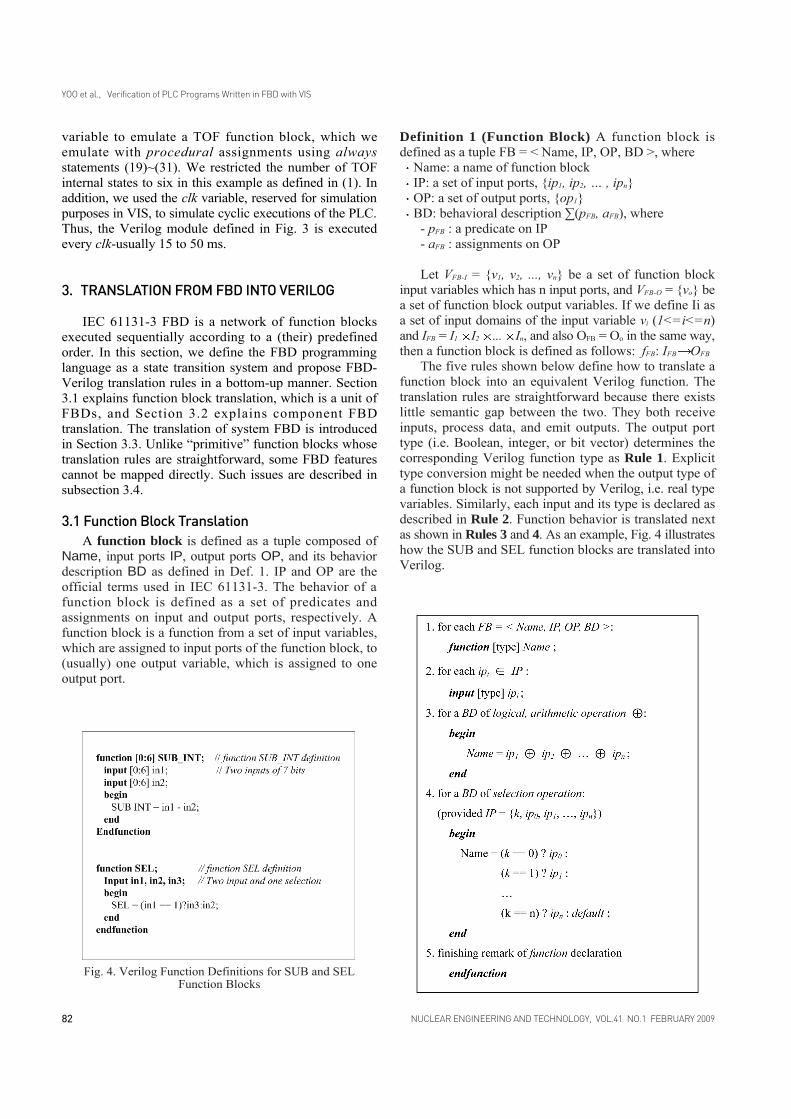
variable to emulate a TOF function block, which weemulate with procedural assignments using alwaysstatements (19)~(31). We restricted the number of TOFinternal states to six in this example as defined in (1). Inaddition, we used the clk variable, reserved for simulationpurposes in VIS, to simulate cyclic executions of the PLC.Thus, the Verilog module defined in Fig. 3 is executedevery clk-usually 15 to 50 ms.
3. TRANSLATION FROM FBD INTO VERILOG
IEC 61131-3 FBD is a network of function blocksexecuted sequentially according to a (their) predefinedorder. In this section, we define the FBD programminglanguage as a state transition system and propose FBD-Verilog translation rules in a bottom-up manner. Section3.1 explains function block translation, which is a unit ofFBDs, and Section 3.2 explains component FBDtranslation. The translation of system FBD is introducedin Section 3.3. Unlike “primitive” function blocks whosetranslation rules are straightforward, some FBD featurescannot be mapped directly. Such issues are described insubsection 3.4.
3.1 Function Block TranslationA function block is defined as a tuple composed of
Name, input ports IP, output ports OP, and its behaviordescription BD as defined in Def. 1. IP and OP are theofficial terms used in IEC 61131-3. The behavior of afunction block is defined as a set of predicates andassignments on input and output ports, respectively. Afunction block is a function from a set of input variables,which are assigned to input ports of the function block, to(usually) one output variable, which is assigned to oneoutput port.
Definition 1 (Function Block) A function block isdefined as a tuple FB = < Name, IP, OP, BD >, where
Name: a name of function blockIP: a set of input ports, {ip1, ip2, … , ipn}OP: a set of output ports, {op1}BD: behavioral description ∑(pFB, aFB), where
- pFB : a predicate on IP- aFB : assignments on OP
Let VFB-I = {v1, v2, ..., vn} be a set of function blockinput variables which has n input ports, and VFB-O = {vo} bea set of function block output variables. If we define Ii asa set of input domains of the input variable vi (1<=i<=n)and IFB = I1 I2 ... In, and also OFB = Oo in the same way,then a function block is defined as follows: fFB: IFB OFB
The five rules shown below define how to translate afunction block into an equivalent Verilog function. Thetranslation rules are straightforward because there existslittle semantic gap between the two. They both receiveinputs, process data, and emit outputs. The output porttype (i.e. Boolean, integer, or bit vector) determines thecorresponding Verilog function type as Rule 1. Explicittype conversion might be needed when the output type ofa function block is not supported by Verilog, i.e. real typevariables. Similarly, each input and its type is declared asdescribed in Rule 2. Function behavior is translated nextas shown in Rules 3 and 4. As an example, Fig. 4 illustrateshow the SUB and SEL function blocks are translated intoVerilog.
82 NUCLEAR ENGINEERING AND TECHNOLOGY, VOL.41 NO.1 FEBRUARY 2009
YOO et al., Verification of PLC Programs Written in FBD with VIS
Fig. 4. Verilog Function Definitions for SUB and SELFunction Blocks

Unlike simple function blocks, translation rules aremore complex when it comes to timer operations. Onemust use reg type variables to track internal information.In addition, a timer's internal variable has to have discretebounds. As a Verilog function cannot hold proceduralassignments that treat reg variables, we use Verilog modulefeature instead.
3.2 Component FBD TranslationA Component FBD is a logical block of independent
function blocks to which a number of function blocks areinterconnected to generate meaningful outputs. Fig. 2 isan example of a component FBD for th_X_Pretrip logic.A component FBD is defined as a tuple composed of aset of function block FBs, a set of transitions T betweenthe function blocks, a set of input ports I, and a set ofoutput ports O. Inputs to a component FBD come fromother component FBDs or system input variables.
Definition 2 (Component FBD) Function block diagramis defined as a tuple Component_FBD = < FBs, T, I, O >,where
FBs: a set of function block FBsT:
- a set of transitions (FBi.OPm, FBj.IPn) betweenfunction blocks FBi and FBj in FBs (provided that i≠ j, and FBj.IPn means nth input port of functionblock FBj)
- (FBi.OPm, FBj.IPn) T, FBi has sequentialexecution precedence on FBj
I: a set of FB.IP which do not appear in T and areassigned by Vcomp_FBD-I
O: a set of FB.OP which do not appear in T and areassigned by Vcomp_FBD-O
The semantics of a component FBD are defined as afunction from a set of input variables to output variables.Let VComp_FBD-I = {vci1,vci2,...,vcim} denote a set of inputvariables entering the FBD and VComp_FBD-O = {vco1,vco2,...,vcon}a set of output variables leaving the FBD. Variables inVComp_FBD-I are assigned to input ports I, and those inVComp_FBD-O are assigned to output ports O. If we define Ias a set of input domains of input variable vci (1<= <=m)and IComp_FBD = I1 I2 ... Im, and OComp_FBD = O1 O2 ...
On in the same way, a component FBD is defined asthe following function: fComponent_FBD: IComp_FBD OComp_FBD
When translating a component FBD, we use theVerilog module construct and assume that all functionblocks have already been translated into Verilogfunctions. A module invokes functions or other modulesaccording to their predefined execution order in the FBDprogram. First, the component FBD's name and ports aredeclared in Rules 6 through 8. Rule 9 declares andinitializes reg type variables. If an output variable is alsoused as input, it is declared as reg type as its value is tobe used in the next cycle. Variable th_Prev_X_Pretrip in
Fig. 2 is such an example. Verilog provides a number offeatures, i.e. for loops, while loops, and case statements,to support succinct description of complex behavior. InRule 10, [Verilog_function_calls] calls every Verilogfunction according to its execution order to generateoutputs of the component FBD. Every function block isseparately translated as a Verilog function and includedin the definition of module for the component FBD. AVerilog definition ends with the reserved word endmodulein Rule 12.
To produce optimal Verilog code, the use of Verilogfunctions must be avoided when equivalent expressionsexist. For example, GE_INT in Fig. 2 can be translatedinto the built-in “f_X >= k_X_Pretrip_Setpoint” expressionor a user-defined function GE_INT; the former translationis preferred. Fig. 3 shows how Rules 1 through 12 areapplied to the FBD shown in Fig. 2. Complete technicaldetails are available elsewhere [15].
3.3 System FBD TranslationThe whole FBD software system is composed of a
number of component FBDs and their interconnections.A System FBD defines the whole software system as atuple composed of component FBDs Component_FBD, aset of transitions T between component FBDs, a set ofinput ports I, and a set of output ports O as defined in Def. 3.
Definition 3 (System FBD) System FBD is defined as atuple System_FBD = < FBDs, T, I, O >, where- FBDs: a set of component FBDs component_FBDs- T:
83NUCLEAR ENGINEERING AND TECHNOLOGY, VOL.41 NO.1 FEBRUARY 2009
YOO et al., Verification of PLC Programs Written in FBD with VIS

- a set of transition (FBDi.Om, FBDj.In) between FBDi
and FBDj in FBDs (provided that i ≠ j and FBDj.In
is an n-th input port of FBDj.- (FBDi.Om, FBDj.In) T, FBDi has a sequential
execution precedence on FBDj
- I: a set of FBD.I which do not appear in T and areassigned by VSys_FBD-I
- O: a set of FBD.O which do not appear in T and reassigned by VSys_FBD-O
Similarly, a system FBD is defined as a function froma set of system input variables VSys_FBD-I = {vsi1,vsi2,...,vsim} toa set of system output variables VSys_FBD-O = {vso1,vso2,...,vson}.If we define Isv as a set of input domains of the inputvariable vsiv(1 <= v <= m) and ISys_FBD = Is1 Is2 ... Ism,and also OSys_FBD = Os1 Os2 ... Osn in the same way,then the system FBD can be regarded as a function:fSystem_FBD: ISys_FBD OSys_FBD
A system FBD contains a number of component FBDsand their sequential interconnections. While translationrules for system FBDs look similar to the rules of componentFBDs, it uses [Verilog_module_instantiations_for_vo]instead of [Verilog_function_calls]. Verilog modules areinstantiated and called according to their execution orderwith outputs communicated. For example, the Verilog
program for the g_LOG_PWR module, a larger systemdepicted in Fig. 5, instantiates 6 modules, M_f_X_Generation~ M_th_X_Trip into SIM_PURPOSE ~ EE, respectively.The Verilog module th_X_Pretrip in Fig. 3 correspondsto a module instantiation “M_th_X_Pretrip EE” in Fig. 5.
84 NUCLEAR ENGINEERING AND TECHNOLOGY, VOL.41 NO.1 FEBRUARY 2009
YOO et al., Verification of PLC Programs Written in FBD with VIS
Fig. 5. A Verilog Program for g_LOG_PWR System FBD

It is important that all component FBDs should be apriori defined as Verilog modules and that their transitionrelations be defined in T of System_FBD. Verilog moduleinstantiations should precisely reflect these transitionrelations. One can translate the whole FBD program intoan equivalent Verilog program hierarchically in a similarmanner.
3.4 Practical Considerations on Translation RulesWhen applying the above rules to large and complex
real-world situations, the following guidelines are useful.First, one must distinguish “intermediate” FBD outputsfrom “externally visible” FBD outputs. That is, outputs ofFBD subsystems must not be mapped as output variables.Rather, they must be declared as “internal” reg variablesin the higher-level Verilog modules. Variable th_Prev_X_Pretrip in Fig. 2 is such an example. Correctness on datadependency and proper ordering among the outputs ofFBD subsystems are critical in translation.
Second, the translation of timer blocks (e.g. TOF andTON) requires synchronization between the global systemclock, clk, and multiple local clocks. Fig. 6 describes atemplate for translating a TOF function block, which hasIN and DELAY as inputs, and OUT and TIME as outputs.IN is an input Boolean variable, and DELAY is a variablespecifying time delay. OUT is an output Boolean variable,and TIME represents the elapsed time of its internal timer.Output value OUT is 0 if input IN remained 0 duringDELAY time periods since input IN changed from 1 to0. Otherwise, the output is 1. The TOF described in Fig.6 has up to 3 bits delay, or 23=8 clock time. Output TIMEis excluded in the Verilog code because it is used tomonitor elapsed time of the local timer for simulation anddebugging purposes only. The local clock of the timer issynchronized with the global clock clk using the “always@(posedge clk) begin”' statement. Each timer block canbe declared as a separate Verilog module, and the behaviorof multiple timers can be unfolded within the componentFBD's definition as shown in Fig. 3.
Third, one must be careful in deciding the number ofbits used to represent timer delay values. Larger valuesexponentially increase the number of states to be explored.In the worst case, state explosion may occur in SMVmodel checking or VIS equivalence checking. Otherblocks (e.g. Bistable or Counters) share the same issue.
4. VIS EQUIVALENCE CHECKING
We applied the proposed translation techniques to asubset of FBDs [16] for APR-1400's RPS BP currentlyunder development in Korea and performed VISequivalence checking on them. As the safety of APR-1400’sRPS must be rigorously demonstrated, regulatory bodiesstrongly recommend that formal verification techniquesbe used. While model checking verifies whether or not
FBD meets required properties, it is inadequate forverifying the behavioral equivalence between two FBDversions. On the other hand, VIS equivalence checking isparticularly useful for checking if FBD design optimizationsdo not introduce errors.
In order to evaluate the effectiveness of the proposedapproach, we conducted a case study using a subset ofthe preliminary version of bistable processor (BP) design.BP, as a part of a reactor protection system, is large andcomplex in that its design specifications, Rev. 02 releasedin 2006, consist of 1,355 function blocks and 1,038variables; when translated using FBD Verifier 1.1, theVerilog program was 7,862 lines long. Section 4.1introduces an overview of the VIS equivalence checkingprocess, and the detailed experimental results are explainedin Section 4.2.
4.1 An Overview of Verification ProcessFig. 7 shows an overview of the VIS equivalence
checking process. FBD designs are programmed with thepSET [17] commercial engineering tool developed by thePLC vendor POSCON. The designs are subsequentlycompiled into executable code. FBD Verifier 1.1 translatesthe design into equivalent Verilog programs in “.v”' format.As the VIS verification system has no graphical userinterface, we executed the VIS in a Cygwin environmentwhere equivalence checking was performed. A program(vl2mv [18]) in the VIS verification system translatesVerilog programs from the “.v” into the “.mv”' format,which VIS can read and analyze. If any evidence ofinequivalence is found, VIS generates a counterexampleillustrating how changes on values of various variableslead to different behavior.
4.2 Experimental ResultWe performed the proposed automatic verification on
85NUCLEAR ENGINEERING AND TECHNOLOGY, VOL.41 NO.1 FEBRUARY 2009
YOO et al., Verification of PLC Programs Written in FBD with VIS
Fig. 6. A Verilog Program for TOF Timer Function Block

a subset of FBDs for APR 1400's RPS BP. The FBD isdepicted in Fig. 2. It is an important part of BP logics, andwas excerpted from a preliminary release of FBDs [16] forthe purpose of this experiment. A different version of FBDis shown in Fig. 8. It should have the same behavior as theFBD in Fig. 2 because it was mechanically synthesizedfrom the same NuSCR requirements specification [19]using a synthesis technique previously reported [20].Synthesis version allows FBD engineers to validatemanually developed and optimized FBD programs even
if the synthesized FBDs do not become part of an officialrelease.
When VIS equivalence checking was performed, toour surprise, VIS determined the behaviors of the twoFBD programs to be different and generated a seven-stepcounterexample (Fig. 9)2. For example, on transition fromstate 0 to 1, the value of “timer” changed from “T0” to “T1.”Such changes are caused by the input f_X of “1011110.”According to the counter-example, the inequivalenceoccurred when the pretrip fired (th_Prev_X_Pretrip = 0in state 6), and then the pretrip condition was released inthe next state 7 on input “0010110.” As the VIS counter-example does not show different output values explicitlyin the final state, we must use the simulation facility ofVIS to fully investigate the cause for the in-equivalenceand fix the errors.
Although the details are beyond the scope of this paper,the SEL function block numbered (15) in Fig. 2 has Ginput wired to th_Prev_X_Pretrip. It means that if thevalue is 1 then it is currently in a normal state, otherwiseit is in a pretrip state. Although Timer function blocksshould not be used when the system is in a pretrip state(i.e., th_Prev_X_Pretrip = 0), TOF timer block numbered(16) is executed after the SEL function block. Suchredundant use of the TOF timer gave rise to differentbehavior, and domain engineers fixed the error byseparating the TOF block so that it is used only when thesystem is in the normal state. Fig. 10 shows the modifiedFBD in which the computation on the TOF block takesprior to that of the SEL block. The VIS equivalencechecking result was also a success (Fig. 11). The modifiedFBD was used in later releases.
We also applied VIS equivalence checking to the
86 NUCLEAR ENGINEERING AND TECHNOLOGY, VOL.41 NO.1 FEBRUARY 2009
YOO et al., Verification of PLC Programs Written in FBD with VIS
2 We edited and visualized it to aid understanding.Fig. 8. A Mechanically Synthesized FBD for th_X_Pretrip Logic
Fig. 7. An Overview of VIS Equivalence Checking

FBDs for “manual reset variable set-point trip logic” ofthe APR-1400 RPS BP, which is more complex than the“fixed set-point rising trip logic” used above. We foundseveral critical errors in both the manually developed andthe synthesized FBD versions (Table 1). In addition tosyntactic and trivial mistakes made by FBD engineers,we also detected several logical errors, which includedsome critical discrepancies between the two FBDs. Sucherrors could not easily be solved by changing the order ofthe function blocks or by replacing them. We even foundlogical errors in the NuSCR requirements specification[19]. All errors were fixed, and the requirements and
design specification documents were updated.As mentioned earlier, analyzing the results of VIS
equivalence checking counterexamples is often timeprohibitive for FBD engineers and verifiers. VIS isexecuted in Cygwin or Linux environments in text mode,and the counterexample generated contains a lot of valueinformation at the bit-level. We also had to rely on VIS'ssimulation to understand the output of FBDs. Even thoughVIS's equivalence checking is an efficient and usefulautomatic verification technique, the above obstaclesrender its widespread use in developing FBD programsdifficult. We are currently developing a tool to assist visual
87NUCLEAR ENGINEERING AND TECHNOLOGY, VOL.41 NO.1 FEBRUARY 2009
YOO et al., Verification of PLC Programs Written in FBD with VIS
Fig. 9. A Counter-Example of VIS Equivalence Checking
Fig. 10. A Modified FBD for th_X_Pretrip

equivalence analyses of counterexamples. Fig. 12 showsan interface design of a VIS Analyzer 0.8 prototype. Fig.12a shows two Verilog programs read, and Fig. 12b is aresult of the automatic execution of several VIS operations,i.e. vl2mv, seq_verify, and simulate.
5. RELATED WORK
Many approaches, including a PLCTOOLS tool-set[22], for the formalization of PLC programs written inLD, ST, and FBD indented for formal verification,validation, and simulation exist in the literature [21].FBD programs are modeled with high-level timed petrinets (HLTPN), and those nets are then used for designvalidation and code generation. MATLAB/SIMULINKprovides a means for specifying and simulating plants.While PLCTOOLS focuses on designing, simulation, andPLC code generation, it does not support formal verificationsuch as VIS equivalence checking.
Higher order logic (HOL) has been used to modelrequirements specifications [23]. There are no restrictionson data types in this approach since function blocks aremodeled as relations on HOL streams. The Verilog weuse has several restrictions on data types, i.e. Verilog hasno real number type variables. It treats time implicitly,
88 NUCLEAR ENGINEERING AND TECHNOLOGY, VOL.41 NO.1 FEBRUARY 2009
YOO et al., Verification of PLC Programs Written in FBD with VIS
Fig. 12. A VIS Analyzer 0.8 Screen-Dump
(a) Two Verilog programs read (b) VIS equivalence checking and simulation result
Table 1. VIS Equivalence Checking Result for APR-1400 RPS BP
Trip Logic
Fixed Set-Point Rising Trip
without Operating Bypass
Manual Reset Variable Set-Point Trip
without Operating Bypass
Error Type
Syntactic
Logical
Syntactic
Logical
Synthesized FBD (Num. of Errors)
0
0
0
6
Original FBD (Num. of Errors)
0
1
3
2
Fig. 11. VIS Verification Result after the Modification

which is contrary to the Verilog and VIS verificationsystems. However, proofs are done with the help of theIsabelle/HOL [24] theorem prover. Compared to automaticverification using VIS, its cost is prohibitive.
In IEC 61499 [25] interactions were defined betweencontrollers and overall systems (plants) using FBDs; theywere formalized [26] with a single-net systems (SNS) [27]model. The controller code was defined in FBD format,and the overall system was organized in IEC 61499function blocks. In this approach, the complete structureis automatically translated into an SNS model using theVerification Environment for Distributed Environment(VEDA) tool. For the combined plant-controller model,model checking was performed using Singal/Event SystemAnalyzer (SESA) [28]. While VIS equivalence checkingverifies FBD programs from a unit module to a wholesystem, it focuses on the interactions between IEC 61499function blocks, which correspond to subsystems and notdetailed IEC 61131-3 function block diagrams.
In case of the automatic formal verification modelchecking of Verilog programs, there are severalapproaches using different model checkers. We haveused the SMV model checker as previously implementedand experimented upon [13, 14]. As explained in Section1, VIS's CTL model checking has some rigorousrestrictions. We used Cadence SMV’s LTL modelchecking to avoid them. CBMC [29] checks Verilog forconsistency with ANSI-C programs. VCEGAR [30]performs model checking on Verilog using a counter-example guided abstraction refinement framework.However, these approaches have not yet been applied tothe development of safety-critical software in industryexcept for the SMV approach.
6. CONCLUSION AND FUTURE WORK
This paper described effective use of VIS, a well-knownverification tool, for automated software verification ofPLC programs written in FBD. We formally definedFBD semantics as a state-transition system, developedtranslation rules from FBD to Verilog programs,implemented FBD Verifier 1.1 software tool to automatethe translation, and performed VIS verification-equivalencechecking on a subset of FBDs currently under developmentfor an APR-1400 nuclear power reactor. The case studydemonstrated that behavioral equivalence checking usingVIS is an effective and useful verification technique thatcan easily be used in developing PLC programs.
As we perform VIS equivalence checking in Cygwinor Linux environment in text mode, automating theverification process and visualizing analysis resultsincluding VIS simulation would promote its applicabilityand usability remarkably. We also introduced a prototypetool design. We are planning on developing a tool suitesupporting development, verification, and safety analysis
throughout entire lifecycle phases from requirementsspecification to implementation.
ACKNOWLEDGEMENTSThe Korean Research Foundation Grant funded by the
Korean Government (KRF-2008-331-D00524) and aKorea University Grant supported this research. Thisresearch was also partially supported by the MKE (Ministryof Knowledge Economy), Korea, under the ITRC(Information Technology Research Center) support programsupervised by the IITA(Institute of Information TechnologyAdvancement) (IITA-2008-(C1090-0801-0032)).
REFERENCES_______________________________[ 1 ] N.G. Leveson, SAFEWARE, System safety and Computers,
Addison Wesley, 1995.[ 2 ] D.A. Peled, SOFTWARE RELIABILITY METHODS,
Springer, 2001.[ 3 ] KNICS, Korea Nuclear Instrumentation & Control System
R&D Center, http://www.knics.re.kr/.[ 4 ] J. Yoo, T. Kim, S. Cha, J.S. Lee, and H.S. Son, “A formal
software requirements specification method for digitalnuclear plants protection systems,” Journal of Systems andSoftware, 74, 1, pp.73-83, 2005.
[ 5 ] NuSRS, http://dependable.kaist.ac.kr/~nusrs.[ 6 ] E.M. Clarke, E.A. Emerson, and A.P. Sistla, “Automatic
verification of finite-state concurrent systems usingtemporal logic specifications,” ACM Trans. ProgrammingLanguages and Systems, 8, 2, pp.244–263, 1986.
[ 7 ] J. Cho, J. Yoo, and S. Cha, “NuEditor - a tool suite forspecification and verification of NuSCR,” SERA2004:SecondACIS International Conference on Software EngineeringResearch, Management and Applications, pp.298–304, 2004.
[ 8 ] IEC, International standard for programmable controllers:Programming languages 61131- Part 3, 1993.
[ 9 ] R.K. Brayton, G.D. Hachtel, A. Sangiovanni-Vincentelli,F. Somenzi, A. Aziz, S.T. Cheng, S.A. Edwards, S.P. Khatri,Y. Kukimoto, A. Pardo, S. Qadeer, R.K. Ranjan, S. Sarwary,T.R. Shiple, G. Swamy, and T. Villa, “VIS : A system forverification and synthesis,” the Eighth InternationalConference on Computer Aided Verification,” CAV ’96,pp.428–432, 1996.
[ 10 ] D.E. Thomas and P.R. Moorby, The Verilog HardwareDescription Language, Kluwer Academic Publishers, 1991.
[ 11 ] E.M. Clarke, O. Grumberg, and D.A. Peled, ModelChecking, MIT Press, 1999.
[ 12 ] Cadence SMV, http://www.cadence.com.[ 13 ] S.J. Jeon, “Verification of Function Block Diagram through
Verilog Translation,” Master’s thesis, Korea AdvancedInstitute of Science and Technology, 2007.
[ 14 ] J. Yoo, E. Jee, and S. Cha, “A Verification framework forFBD based software in nuclear power plants,” The 15thAsian Pacific Software Engineering Conference (APSEC2008), pp.385-392, 2008.
[ 15 ] J. Yoo, Synthesis of Function Block Diagrams from NuSCRFormal Specification, Ph.D. thesis, Korea AdvancedInstitute of Science and Technology, 2005.
[ 16 ] KAERI, SDS for reactor protection system, KNICS-RPS-SDS101 Rev.00 Draft, Sept. 2003.
[ 17 ] S. Cho, K. Koo, B. You, T.W. Kim, T. Shim, and J.S. Lee,
89NUCLEAR ENGINEERING AND TECHNOLOGY, VOL.41 NO.1 FEBRUARY 2009
YOO et al., Verification of PLC Programs Written in FBD with VIS
“Development of the loader software for PLC programming,”Conference of the Institute of Electronics Engineers ofKorea, pp.959–960, 2007.
[ 18 ] S.T. Cheng and R.K. Brayton, “Compiling verilog intoautomata,” Tech. Rep. UCB/ERL M94/37, EECS Department,University of California, Berkeley, 1994.
[ 19 ] KAERI, SRS for Reactor Protection System, KNICS-RPS-SRS101 REV.00, Feb. 2003.
[ 20 ] J. Yoo, S. Cha, C.H. Kim, and D.Y. Song, “Synthesis ofFBD-based PLC design from NuSCR formal specification,”Reliability Engineering and System Safety, 87, 2, pp.287-294, 2005.
[ 21 ] G. Frey and L. Litz, “Formal moethods in PLC programming,”IEEE Conference in System Man and Cybernetics:SMC2000, 2000.
[ 22 ] L. Baresi, M. Mandrioli, S. Morasca, and M. Pezz`e, “Plctools:Design, formal verification, and code generation forprogrammable controllers,” the IEEE Conference on System,Man, and Cybernetics (SMC), Nashville, USA, pp.2437-2442, Oct. 2000.
[ 23 ] B.J. Kramer and N. Volker, “A higher dependable computerarchitecture for safety critical control applications,” Real-
Time Systems Journal, 13, 3, pp.237-251, 1997.[ 24 ] T. Nipkow, L.C. Paulson, and M. Wenzel, Isabelle/HOL -
A Proof Assistant for Higher-Order Logic, LNCS, vol.2283,Springer, 2002.
[ 25 ] IEC, Function blocks - Part 1: Architecture (IEC 61499-1),2005.
[ 26 ] V. Vyatkin and H.M. Hanisch, “Modeling of IEC 61499function blocks - a cue to their verification,” XI Workshopon Supervising and Diagnostics of Machining System,pp.59-68, 2000.
[ 27 ] P.H. Starke, “Symmetries of signal-net systems,” Workshopon Concurrency, Specification and Programming, pp.285-297, 2000.
[ 28 ] P.H. Starke and S. Roch, “Tools for formal specification,verification, and validation of requirements,” the 12th AnnualConference on Computer Assurance, COMPASS ’97, pp.35-47, 1997.
[ 29 ] Bounded Model Checking for ANSI-C, http://www.cs.cmu.edu/~modelcheck/cbmc.
[ 30 ] H. Jain, N. Sharygina, D. Kroening, and E. Clarke, “Wordlevel predicate abstraction and refinement for verifying rtlverilog,” 42nd Design Automation Conference (DAC), 2005.
90 NUCLEAR ENGINEERING AND TECHNOLOGY, VOL.41 NO.1 FEBRUARY 2009
YOO et al., Verification of PLC Programs Written in FBD with VIS