
Solution: FBD for Link AB
2
M(x) 1 -10 V(x) 5 10 2.5 -7.5 Example 9.14 Draw the shear force and bending moment diagrams in the plot axes below for the loaded beam shown. Solution: FBD for Link AB: ! = 0: ! 2 − 10 1 = 0 => ! = 5 ! = 0: ! + ! − 10 = 0 => ! = 5 FBD for link BD: ! = 0: 5 1 + ! = 0 => ! = −5 ! = 0: ! + ! − ! − 10 = 0 => ! = 20 Shear Force Diagram and Bending Moment Diagram
Transcript of Solution: FBD for Link AB
M(x)
1
-10
V(x)
5
10
2.5
-7.5
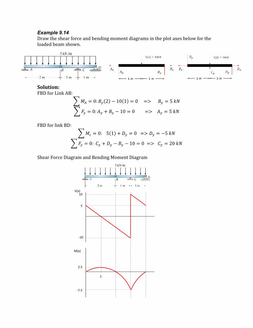
Example 9.14 Drawtheshearforceandbendingmomentdiagramsintheplotaxesbelowfortheloadedbeamshown.
Solution:FBDforLinkAB:
𝑀! = 0:𝐵! 2 − 10 1 = 0 => 𝐵! = 5 𝑘𝑁
𝐹! = 0:𝐴! + 𝐵! − 10 = 0 => 𝐴! = 5 𝑘𝑁FBDforlinkBD:
𝑀! = 0: 5 1 + 𝐷! = 0 => 𝐷! = −5 𝑘𝑁
𝐹! = 0: 𝐶! + 𝐷! − 𝐵! − 10 = 0 => 𝐶! = 20 𝑘𝑁ShearForceDiagramandBendingMomentDiagram


